EP2875914A1 - Robot simulator, robot teaching device and robot teaching method - Google Patents
Robot simulator, robot teaching device and robot teaching method Download PDFInfo
- Publication number
- EP2875914A1 EP2875914A1 EP12881268.2A EP12881268A EP2875914A1 EP 2875914 A1 EP2875914 A1 EP 2875914A1 EP 12881268 A EP12881268 A EP 12881268A EP 2875914 A1 EP2875914 A1 EP 2875914A1
- Authority
- EP
- European Patent Office
- Prior art keywords
- robot
- virtual image
- control point
- teaching
- unit
- Prior art date
- Legal status (The legal status is an assumption and is not a legal conclusion. Google has not performed a legal analysis and makes no representation as to the accuracy of the status listed.)
- Withdrawn
Links
Images


Classifications
-
- B—PERFORMING OPERATIONS; TRANSPORTING
- B25—HAND TOOLS; PORTABLE POWER-DRIVEN TOOLS; MANIPULATORS
- B25J—MANIPULATORS; CHAMBERS PROVIDED WITH MANIPULATION DEVICES
- B25J9/00—Program-controlled manipulators
- B25J9/16—Program controls
- B25J9/1602—Program controls characterised by the control system, structure, architecture
- B25J9/1605—Simulation of manipulator lay-out, design, modelling of manipulator
-
- B—PERFORMING OPERATIONS; TRANSPORTING
- B25—HAND TOOLS; PORTABLE POWER-DRIVEN TOOLS; MANIPULATORS
- B25J—MANIPULATORS; CHAMBERS PROVIDED WITH MANIPULATION DEVICES
- B25J9/00—Program-controlled manipulators
- B25J9/16—Program controls
- B25J9/1656—Program controls characterised by programming, planning systems for manipulators
- B25J9/1671—Program controls characterised by programming, planning systems for manipulators characterised by simulation, either to verify existing program or to create and verify new program, CAD/CAM oriented, graphic oriented programming systems
-
- G—PHYSICS
- G06—COMPUTING OR CALCULATING; COUNTING
- G06N—COMPUTING ARRANGEMENTS BASED ON SPECIFIC COMPUTATIONAL MODELS
- G06N20/00—Machine learning
-
- G—PHYSICS
- G05—CONTROLLING; REGULATING
- G05B—CONTROL OR REGULATING SYSTEMS IN GENERAL; FUNCTIONAL ELEMENTS OF SUCH SYSTEMS; MONITORING OR TESTING ARRANGEMENTS FOR SUCH SYSTEMS OR ELEMENTS
- G05B2219/00—Program-control systems
- G05B2219/30—Nc systems
- G05B2219/40—Robotics, robotics mapping to robotics vision
- G05B2219/40311—Real time simulation
-
- Y—GENERAL TAGGING OF NEW TECHNOLOGICAL DEVELOPMENTS; GENERAL TAGGING OF CROSS-SECTIONAL TECHNOLOGIES SPANNING OVER SEVERAL SECTIONS OF THE IPC; TECHNICAL SUBJECTS COVERED BY FORMER USPC CROSS-REFERENCE ART COLLECTIONS [XRACs] AND DIGESTS
- Y10—TECHNICAL SUBJECTS COVERED BY FORMER USPC
- Y10S—TECHNICAL SUBJECTS COVERED BY FORMER USPC CROSS-REFERENCE ART COLLECTIONS [XRACs] AND DIGESTS
- Y10S901/00—Robots
- Y10S901/02—Arm motion controller
- Y10S901/03—Teaching system
- Y10S901/05—Machine driven lead through
Definitions
- the embodiment disclosed herein relates to a robot simulator, a robot teaching device, and a robot teaching method.
- the teaching data is created by using what is called a teach pendant that is a portable device dedicated to teaching the robot. In general, operating the teach pendant requires a certain level of skill and experience of the operator.
- Patent Literature 1 Japanese Patent No. 3901772
- the conventional robot simulators have much room for improvement in that they can enable the operator to intuitively and easily perform operation irrespective of the skill or experience of the operator.
- a robot simulator displays touch keys describing directions of motion of a robot as described above, and the robot has multiple axes and is movable in multiple directions, many touch keys need to be displayed. This makes it all the more difficult for the operator to operate the robot simulator.
- the directions described by, for example, “left” or “right” as described above indicate relative directions, not absolute directions. This may prevent the operator from intuitively recognizing the direction of the robotic motion.
- a robot simulator includes a display unit, a generation unit, a display controller, and a simulation instruction unit.
- the generation unit generates a virtual image of a robot, the virtual image including an operating handle that is capable of operating axes of a three-dimensional coordinate in which an origin is a certain control point of the robot.
- the display controller causes the display unit to display the virtual image generated by the generation unit.
- the simulation instruction unit acquires, when an operation on the operating handle by an operator is received, an amount of displacement of the control point and an amount of rotation of the three-dimensional coordinate axes based on the operation, and causes the generation unit to regenerate the virtual image of the robot whose posture is changed in accordance with the acquired amount of displacement and the acquired amount of rotation.
- the operator can intuitively and easily perform operation irrespective of the skill or experience of the operator.
- the following describes, as an example, a robot simulator that displays a three-dimensional computer graphics image of a robot on a display unit such as a display.
- the three-dimensional computer graphics image may be hereinafter referred to as a "virtual image”.
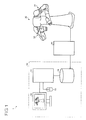
- FIG. 1 is a schematic diagram illustrating the entire configuration of a robot system 1 including a robot simulator 10 according to the embodiment.
- the robot system 1 includes the robot simulator 10, a robot controller 20, and a robot 30.
- the robot simulator 10 includes a simulator controller 11, a display unit 12, an operating unit 13, and a teaching point information database (DB) 14.
- DB teaching point information database
- the simulator controller 11 controls the entire robot simulator 10, and is configured by, for example, an arithmetic processing device and a storage device.
- the simulator controller 11 is communicably connected to each unit of the robot simulator 10 such as the display unit 12.
- the simulator controller 11 outputs, to the display unit 12, a virtual image of the robot 30 whose simulated motion is calculated on the basis of an operation by an operator via the operating unit 13.
- the simulator controller 11 also acquires teaching points of the robot 30 from the virtual image of the robot 30 on the basis of the operation by the operator via the operating unit 13, and registers the teaching points in the teaching point information DB 14.
- the display unit 12 is a display device such as a display.
- the operating unit 13 is a pointing device such as a mouse.
- the operating unit 13 is not necessarily configured by a hardware component, but may be configured by a software component such as touch keys displayed on a touch screen, for example.
- the teaching point information DB 14 stores therein information relating to teaching points of the robot 30.
- the teaching points are information on a target posture of the robot 30 that the robot 30 needs to pass through when the robot 30 plays back the simulated motion, and are stored as a pulse count of encoders included in the robot 30, for example. Because the robot 30 operates on the basis of information on a plurality of teaching points, the teaching point information DB 14 stores therein a plurality of teaching points of each motion (job) of the robot 30 in a manner in which a motion of the robot 30 is associated with a plurality of teaching points.
- a teaching program of the robot 30 includes combined information of a plurality of teaching points and interpolation commands between the teaching points, and operation commands on an end effector.
- the teaching point information DB 14 stores therein information on teaching points of each teaching program of the robot 30, and the robot 30 operates on the basis of the teaching program when the robot 30 plays back the simulated motion.
- the teaching point information DB 14 is communicably connected to the robot controller 20 that controls the physical motion of the robot 30.
- the robot controller 20 controls various types of physical motions of the robot 30 on the basis of the teaching points registered in the teaching point information DB 14.
- teaching point information DB 14 and the simulator controller 11 are configured as separate units in the example of FIG. 1 to make description simple, the teaching point information DB 14 may be stored in a storage unit included in the simulator controller 11.
- the robot 30 includes a first arm 31 and a second arm 32, and the first and the second arms 31 and 32 each include a plurality of joints for changing their positions, and actuators that actuate the joints.
- Each actuator includes a servo motor that drives a corresponding joint of the robot 30 on the basis of an operation instruction from the robot controller 20.
- end parts of the first arm 31 and the second arm 32 are provided with a hand 31A and a hand 32A (grippers), respectively, as end effectors.
- the hand 31A and the hand 32A may hold a certain handling tool (hereinafter referred to as a tool) depending on the nature of the work the robot 30 performs.
- the robot 30 is illustrated as a dual-arm robot having a pair of arms, the first arm 31 and the second arm 32, in the example of FIG. 1 , the robot used in the robot system 1 may be a single-arm robot or a multi-arm robot having two or more arms.
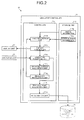
- FIG. 2 is a block diagram of the robot simulator 10 according to the embodiment.
- FIG. 2 only illustrates components necessary for the description of the robot simulator 10, and general components are omitted from FIG. 2 .
- the simulator controller 11 includes a controller 111 and a storage unit 112.
- the controller 111 includes an image generation unit 111a, a display controller 111b, an operation reception unit 111c, an operating amount acquisition unit 111d, a simulation instruction unit 111e, a teaching point acquisition unit 111f, and a registration unit 111g.
- the storage unit 112 stores therein model information 112a and control point information 112b.
- the image generation unit 111a generates a virtual image of the robot 30 on the basis of the model information 112a and the control point information 112b.
- the model information 112a contains drawing information defined in advance according to the type of the robot 30.
- the control point information 112b defines in advance a control point of the robot 30.
- the image generation unit 111a generates a virtual image of the robot 30 that includes an operating handle (to be described later) that is capable of operating axes of a three-dimensional coordinate in which the origin is the control point of the robot 30.
- the detail of the control point information 112b will be described later with reference to FIG. 4 .
- the image generation unit 111a outputs the generated virtual image of the robot 30 to the display controller 111b.
- the display controller 111b causes the display unit 12 to display the virtual image of the robot 30 received from the image generation unit 111a.
- Described here is an example of a virtual image of the robot 30 generated by the image generation unit 111a and displayed on the display unit 12 via the display controller 111b with reference to FIG. 3 .
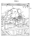
- FIG. 3 is a schematic diagram illustrating an example of a virtual image of the robot 30 displayed on the display unit 12. As illustrated in FIG. 3 , the virtual image of the robot 30 is displayed on a display window 120 that is one of display areas of the display unit 12.
- the virtual image of the robot 30 includes a certain control point and an operating handle that is capable of operating the axes of the three-dimensional coordinate in which the origin is the control point.
- FIG. 3 illustrates, for example, a virtual image of the robot 30 including a control point CP1 and a control point CP2, and an operating handle H1 for operating three-dimensional coordinate axes with the origin being the control point CP1, and an operating handle H2 for operating three-dimensional coordinate axes with the origin being the control point CP2.
- the operating handles H1 and H2 are operational objects that can be operated by, for example, a drag operation by the operator via the operating unit 13.
- the position of a certain control point such as the control points CP1 and CP2 is defined by the control point information 112b described above. Described next is an example of a setting of the control point information 112b with reference to FIG. 4 .
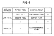
- FIG. 4 is a diagram illustrating an example of a setting of the control point information 112b.
- the control point information 112b includes, for example, items of "with or without tool”, items of "type of tool”, and items of "control point”.
- the data of each item is described in text to make description simple, this is not intended to limit the format of the data to be stored.
- data is stored that determines whether a tool is held by the hand 31A and the hand 32A, that is, whether the robot 30 operates "with tool” or "without tool”.
- data is stored indicating types of tools.
- control point data (such as coordinate values indicating a position of a control point relative to the hand 31A or the hand 32A) is stored indicating a control point corresponding to a type of a tool.
- a "hand reference point” set in advance is determined to be a certain control point.
- control point information 112b is a database that associates a type of a tool used by the robot 30 with a control point set in advance in accordance with the type of the tool.
- the image generation unit 111a described above acquires a control point corresponding to a type of a tool assumed to be used by the robot 30 from the control point information 112b, and generates a virtual image of the robot 30 on the basis of the acquired control point.
- the virtual image of the robot 30 also includes an operating handle H3 that operates an angle of an elbow of the robot 30 and an operating handle H4 that operates the rotation axis of the waist of the robot 30.
- the operating handles H3 and H4 are also operational objects that can be operated by the operator via the operating unit 13.
- the operator operates the operating handles H1 to H1
- the virtual image of the robot 30 can include peripherals of the robot 30.
- the operator when the operator causes the robot 30 in the virtual image to perform a simulated motion, the operator can check whether the robot 30 collides with the peripherals.
- the display window 120 is provided with input buttons B1 to B3.
- the input buttons B1 to B3 are also operational objects that can be operated by the operator via the operating unit 13.
- a function of switching display and non-display of the operating handles H1 to H4 may be assigned to the input button B1.
- a function of displaying a tool name may be assigned to the input button B2.
- a registration function may be assigned to the input button B3 for registering the posture of the robot 30 as teaching points in the teaching point information DB 14 at the time at which the input button B3 is pushed.
- the display window 120 is also provided with a pull-down menu P1.
- a function of switching coordinate systems such as base coordinates, robot coordinates, or tool coordinates
- base coordinates such as base coordinates, robot coordinates, or tool coordinates
- the image generation unit 111a When the operator selects a desired coordinate system from the pull-down menu P1, the image generation unit 111a generates a virtual image of the robot 30 in accordance with the selected coordinate system.
- the shape of the operating handles H1 to H4 may be switched depending on the selected coordinate system so that the operator can intuitively recognize the handles and can easily operate them.
- display and non-display of the peripherals of the robot 30 may also be switched.
- the following describes the operation reception unit 111c of the simulator controller 11.
- the operation reception unit 111c receives an input operation of the operator via the operating unit 13.
- the operation reception unit 111c notifies the operating amount acquisition unit 111d of the received input operation.
- the input operation relating to a simulation instruction described herein corresponds to the operation on the operating handles H1 to H4 in the example of FIG. 3 described above.
- the operation reception unit 111c notifies the teaching point acquisition unit 111f of the received input operation.
- the input operation relating to an instruction to register teaching points described herein corresponds to the operation on the input button B3 in the example of FIG. 3 described above.
- the operating amount acquisition unit 111d analyzes the content of the input operation notified by the operation reception unit 111c, and acquires an amount of displacement of a control point and an amount of rotation of three-dimensional coordinate axes with the origin being the control point.
- the operating amount acquisition unit 111d notifies the simulation instruction unit 111e of the acquired amounts of displacement and rotation.
- the simulation instruction unit 111e notifies the image generation unit 111a of a simulation instruction that causes the image generation unit 111a to regenerate the virtual image of the robot 30 whose posture is changed in accordance with the amount of displacement and the amount of rotation notified by the operating amount acquisition unit 111d.
- the image generation unit 111a regenerates the virtual image of the robot 30 on the basis of the simulation instruction received from the simulation instruction unit 111e, and the regenerated virtual image is displayed on the display unit 12 via the display controller 111b.
- the robot 30 in the virtual image performs continuously changing simulated motion.
- a reference sign "H” is given to the operating handle, and a reference sign "CP" is given to the control point.
- FIG. 5A is a diagram illustrating an example of an operating handle H.
- FIG. 5B is a diagram illustrating a displacement handle Hx.
- FIG. 5C is a diagram illustrating a rotation handle HRx.
- FIG. 5A three-dimensional XYZ coordinate axes are illustrated, where X, Y, and Z are all capital letters.
- the XYZ coordinate axes are, for example, what is called the world coordinate system that represents the whole space.
- the coordinate system of the operating handle H to be described below is represented by xyz coordinate axes that represent a local coordinate system different from the world coordinate system. To make description simple, it is assumed that the x-axis, the y-axis, and the z-axis are parallel to the X-axis, the Y-axis, and the Z-axis, respectively.
- the operating handle H is an operational object used for operating the xyz coordinate axes with the origin being a control point CP.
- the operating handle H includes displacement handles Hx, Hy, and Hz each displacing the control point CP in the direction along a corresponding axis of the xyz coordinate axes.
- the displacement handles Hx, Hy, and Hz each have a solid double-pointed-arrow shape along the direction of a corresponding axis of the xyz coordinate axes.
- the displacement handles Hx, Hy, and Hz are each disposed in a position separated from the control point CP.
- the operating handle H includes rotation handles HRx, HRy, and HRz each rotating the corresponding axis of the xyz coordinate axes about the coordinate axis.
- the rotation handles HRx, HRy, and HRz each have a solid double-pointed-arrow shape around a corresponding axis of the xyz coordinate axes.
- Described here is the displacement handle Hx with reference to FIG. 5B , and described is a specific example with regard to a case in which the displacement handle Hx is operated.
- FIG. 5B illustrations of the displacement handles Hy and Hz and the rotation handles HRx, HRy and HRz are omitted.
- the displacement handle Hx is operated by a drag operation by the operator via the operating unit 13 (see an arrow 501 in FIG. 5B ).
- the displacement handle Hx can be dragged along the x-axis direction corresponding to the displacement handle Hx.
- the image generation unit 111a displaces the control point CP and the xyz coordinate axes with the origin being the control point CP by 1 in the direction along the x-axis (see an arrow 502 in FIG. 5B ).
- the image generation unit 111a regenerates the virtual image of the robot 30 on the basis of the control point CP and the xyz coordinate axes after the displacement to cause the robot 30 in the virtual image to perform a simulated motion.
- the displacement handle Hx can also be dragged in the opposite direction of the arrow 501 in FIG. 5B as indicated by the solid double-pointed-arrow shape of the displacement handle Hx.
- the displacement handles Hy and Hz also displace the control point CP and the xyz coordinate axes with the origin being the control point CP in the directions along the y-axis and the z-axis, respectively, by being dragged by the operator in the same manner as in the case of the displacement handle Hx.
- FIG. 5C Described next is the rotation handle HRx with reference to FIG. 5C , and described is a specific example with regard to a case in which the rotation handle HRx is operated.
- FIG. 5C illustrations of the displacement handles Hx, Hy, and Hz and the rotation handles HRy and HRz are omitted.
- the rotation handle HRx is also operated by a drag operation by the operator via the operating unit 13 (see an arrow 503 in FIG. 5C ).
- the rotation handle HRx can be dragged in the direction around the x-axis corresponding to the rotation handle HRx.
- the image generation unit 111a rotates the xyz coordinate axes by 30 degrees around the x-axis (see arrows 504 in FIG. 5C ).
- the image generation unit 111a regenerates the virtual image of the robot 30 on the basis of the xyz coordinate axes after the rotation to cause the robot 30 in the virtual image to perform a simulated motion.
- the rotation handle HRx can also be dragged in the opposite direction of the arrow 503 in FIG. 5C as indicated by the solid double-pointed-arrow shape of the rotation handle HRx.
- the xyz coordinate axes are rotated in the direction opposite to the direction illustrated in the example of FIG. 5C .
- the rotation handles HRy and HRz also rotate the xyz coordinate axes about the y-axis and the z-axis, respectively, by being dragged by the operator in the same manner as in the case of the rotation handle HRx.
- the operating handle H includes the displacement handles Hx, Hy, and Hz and the rotation handles HRx, HRy, and HRz corresponding to the xyz coordinate axes with the origin being the control point CP, respectively, and each having a shape of a double-pointed arrow.
- the shape of the operating handle H is not limited to the example illustrated in FIG. 5A .
- the shape of the displacement handles Hx, Hy, and Hz and the rotation handles HRx, HRy, and HRz may be a single-pointed arrow, for example.
- FIG. 6 is a diagram illustrating an operating handle H' according to a modification
- the displacement handles Hx, Hy, and Hz may be disposed such that they intersect with each other at the control point CP.
- the operator can intuitively and easily perform operation irrespective of the skill or experience of the operator in the same manner as in the case of the operating handle H illustrated in FIG. 5A .
- FIGS. 7A to 7C are diagrams illustrating a specific example of a simulated motion performed by the robot 30 in a virtual image when the displacement handle Hz is operated.
- FIGS. 7A to 7C it is assumed that the center part of the end moving part of the first arm 31 included in the robot 30 is defined as the control point CP.
- illustrations of the rotation handles HRx, HRy, and HRz are omitted from FIGS. 7A to 7C .
- the operating handle H is displaced in the direction along the z-axis (see an arrow 702 in FIG. 7B ) by a displacement amount corresponding to a dragged amount of the drag operation by the operator.
- the control point CP and the xyz coordinate axes with the origin being the control point CP are temporarily separated, as a whole, from the end moving part of the first arm 31, and are displaced in the direction along the z-axis.
- the end moving part of the first arm 31 moves toward the control point CP so that the center part of the end moving part agrees with the control point CP as before.
- a virtual image of the robot 30 performing a simulated motion is illustrated in which the robot 30 moves the first arm 31 in the direction of an arrow 703 in FIG. 7C .
- FIGS. 7A to 7C illustrate an example of a simulated motion in the case of operating the displacement handle Hz, it is apparent that, when the displacement handles Hx and Hy are operated, the same kind of simulated motion is illustrated with respect to the corresponding x-axis and the y-axis.
- FIGS. 8A to 8C are diagrams illustrating a specific example of a simulated motion performed by the robot 30 in a virtual image when the rotation handle HRx is operated.
- FIGS. 8A to 8C it is also assumed that the center part of the end moving part of the first arm 31 is defined as the control point CP. To make description simple, illustrations of the displacement handles Hx, Hy, and Hz are omitted from FIGS. 8A to 8C .
- the display window 120 of the display unit 12 displays a virtual image of the robot 30 (mainly the first arm 31) and that the rotation handle HRx is dragged by the operator in the direction indicated by an arrow 801 in FIG. 8A .
- the xyz coordinate axes are rotated about the x-axis (see arrows 802 in FIG. 8B ) by a rotation amount corresponding to a dragged amount of the drag operation by the operator.
- the end moving part of the first arm 31 is illustrated such that it follows the rotation of the xyz coordinate axes.
- a virtual image of the first arm 31 performing a simulated motion is illustrated in which the orientation of the end moving part is changed in the direction along an arrow 803 in FIG. 8C .
- FIGS. 8A to 8C illustrate an example of a simulated motion in the case of operating the rotation handle HRx, it is apparent that, when the rotation handles HRy and HRz are operated, the same kind of simulated motion is illustrated with respect to the corresponding y-axis and the z-axis.
- the description returns to FIG. 2 .
- the teaching point acquisition unit 111f receives a notification from the operation reception unit 111c notifying that the input button B3 (see FIG. 3 ) is pushed, and acquires the posture of the robot 30 in the virtual image as teaching points at the time at which the input button B3 is pushed.
- the teaching point acquisition unit 111f notifies the registration unit 111g of the acquired teaching points.
- the registration unit 111g registers the teaching points received from the teaching point acquisition unit 111f in the teaching point information DB 14.
- the robot controller 20 controls various types of physical motions of the robot 30 on the basis of the teaching points registered in the teaching point information DB 14.
- the teaching point acquisition unit 111f and the registration unit 111g may be referred to as a "teaching unit” that teaches the robot 30 via the teaching point information DB 14.
- the storage unit 112 is a storage device such as a hard disk drive or a non-volatile memory, and stores therein the model information 112a and the control point information 112b.
- the details of the model information 112a and the control point information 112b have already been described, and thus the description thereof is omitted.
- the simulator controller 11 may acquire, as necessary, information required for generating the virtual image from a host device that is mutually communicably connected with the simulator controller 11.
- the robot simulator includes a display unit, an image generation unit (generation unit), a display controller, and a simulation instruction unit.
- the display unit displays an image.
- the image generation unit generates a virtual image of a robot.
- the virtual image includes an operating handle that is capable of operating three-dimensional coordinate axes with the origin being a certain control point of the robot.
- the display controller causes the display unit to display the virtual image generated by the image generation unit.
- the simulation instruction unit acquires, when an operation on the operating handle by an operator is received, an amount of displacement of the control point and an amount of rotation of the three-dimensional coordinate axes based on the operation, and causes the image generation unit to regenerate the virtual image of the robot whose posture is changed in accordance with the acquired amounts of displacement and rotation.
- the robot simulator according to the embodiment enables the operator to intuitively and easily perform operation irrespective of the skill or experience of the operator.
- a robot simulator is described, as an example, that acquires the posture of a robot in a virtual image as teaching points and can register the teaching points as teaching point information
- a robot simulator may be configured as a robot teaching device.
- the simulated motion may be physically performed by the robot in accordance with an operation on the operating handle by the operator.
- a multi-axis robot having two arms is described as an example, the description is not intended to limit the number of arms or axes of the robot, nor intended to specify the type of the robot or the shape of the robot.
- the display unit may be configured, for example, by a touch panel that supports multi-touch operation and the operating handle may be dragged by a multi-touch operation of the operator on the touch panel.
- the virtual image is a three-dimensional computer graphics image
- the description is not intended to limit the dimension of the virtual image, and the virtual image may be a two-dimensional image.
Landscapes
- Engineering & Computer Science (AREA)
- Theoretical Computer Science (AREA)
- Software Systems (AREA)
- Robotics (AREA)
- Mechanical Engineering (AREA)
- Medical Informatics (AREA)
- Data Mining & Analysis (AREA)
- Evolutionary Computation (AREA)
- Computer Vision & Pattern Recognition (AREA)
- Artificial Intelligence (AREA)
- Physics & Mathematics (AREA)
- Computing Systems (AREA)
- General Engineering & Computer Science (AREA)
- General Physics & Mathematics (AREA)
- Mathematical Physics (AREA)
- Automation & Control Theory (AREA)
- Manipulator (AREA)
- Numerical Control (AREA)
Abstract
A robot simulator (10) according to an aspect of an embodiment includes a display unit (12), an image generation unit (111a), a display controller (111b), and a simulation instruction unit (111e). The display unit (12) displays an image. The image generation unit (111a) generates a virtual image of a robot (30). The virtual image includes an operating handle capable of operating axes of a three-dimensional coordinate in which the origin is a certain control point of the robot (30). The display controller (111b) causes the display unit (12) to display the virtual image. The simulation instruction unit (111e) acquires, when an operation on the operating handle by an operator is received, a displacement amount of the control point and a rotation amount of the three-dimensional coordinate axes based on the operation, and causes the image generation unit (111a) to regenerate the virtual image of the robot (30) whose posture is changed according to the acquired displacement and rotation axmounts.
Description
- The embodiment disclosed herein relates to a robot simulator, a robot teaching device, and a robot teaching method.
- Various types of robot simulators have been proposed that previously simulate and calculate the motion of a robot on the basis of teaching data created by causing the robot to perform, for example, certain processing work, and display graphics images of the robot on, for example, a display of a computer.
- With these robot simulators, operators can create teaching data while checking whether the robot collides with the peripherals without depending on the actual operation of the robot.
- The teaching data is created by using what is called a teach pendant that is a portable device dedicated to teaching the robot. In general, operating the teach pendant requires a certain level of skill and experience of the operator.
- To facilitate the teaching of a robot, a method has more recently been developed in which touch keys describing directions of motion such as "up", "down", "left", and "right" are displayed around graphics images of the robot displayed on a touch panel so that the operator can teach the robot by pushing the touch keys (see
Patent Literature 1, for example). - Patent Literature 1: Japanese Patent No.
3901772 - The conventional robot simulators have much room for improvement in that they can enable the operator to intuitively and easily perform operation irrespective of the skill or experience of the operator.
- When, for example, a robot simulator displays touch keys describing directions of motion of a robot as described above, and the robot has multiple axes and is movable in multiple directions, many touch keys need to be displayed. This makes it all the more difficult for the operator to operate the robot simulator.
- Moreover, the directions described by, for example, "left" or "right" as described above indicate relative directions, not absolute directions. This may prevent the operator from intuitively recognizing the direction of the robotic motion.
- In view of the description above, it is an object of an aspect of the present embodiment to provide a robot simulator, a robot teaching device, and a robot teaching method that enable an operator to intuitively and easily perform operation irrespective of the skill or experience of the operator.
- A robot simulator according to an aspect of an embodiment includes a display unit, a generation unit, a display controller, and a simulation instruction unit. The generation unit generates a virtual image of a robot, the virtual image including an operating handle that is capable of operating axes of a three-dimensional coordinate in which an origin is a certain control point of the robot. The display controller causes the display unit to display the virtual image generated by the generation unit. The simulation instruction unit acquires, when an operation on the operating handle by an operator is received, an amount of displacement of the control point and an amount of rotation of the three-dimensional coordinate axes based on the operation, and causes the generation unit to regenerate the virtual image of the robot whose posture is changed in accordance with the acquired amount of displacement and the acquired amount of rotation.
- According to an aspect of the embodiment, the operator can intuitively and easily perform operation irrespective of the skill or experience of the operator.
-
-
FIG. 1 is a schematic diagram illustrating the entire configuration of a robot system including a robot simulator according to an embodiment. -
FIG. 2 is a block diagram illustrating a configuration of the robot simulator according to the embodiment. -
FIG. 3 is a schematic diagram illustrating an example of a virtual image displayed on a display unit. -
FIG. 4 is a diagram illustrating an example of a setting of control point information. -
FIG. 5A is a diagram illustrating an example of an operating handle. -
FIG. 5B is a diagram illustrating a displacement handle. -
FIG. 5C is a diagram illustrating a rotation handle. -
FIG. 6 is a diagram illustrating an operating handle according to a modification. -
FIG. 7A is a first diagram illustrating a specific example of a simulated motion of a robot in a virtual image when a displacement handle is operated. -
FIG. 7B is a second diagram illustrating a specific example of a simulated motion of the robot in the virtual image when the displacement handle is operated. -
FIG. 7C is a third diagram illustrating a specific example of a simulated motion of the robot in the virtual image when the displacement handle is operated. -
FIG. 8A is a first diagram illustrating a specific example of a simulated motion of the robot in a virtual image when a rotation handle is operated. -
FIG. 8B is a second diagram illustrating a specific example of a simulated motion of the robot in the virtual image when the rotation handle is operated. -
FIG. 8C is a third diagram illustrating a specific example of a simulated motion of the robot in the virtual image when the rotation handle is operated. - The following describes in detail an embodiment of a robot simulator, a robot teaching device, and a robot teaching method disclosed in the present invention with reference to the accompanying drawings. The embodiment described below is not intended to limit the scope of the present invention.
- The following describes, as an example, a robot simulator that displays a three-dimensional computer graphics image of a robot on a display unit such as a display. The three-dimensional computer graphics image may be hereinafter referred to as a "virtual image".
-
FIG. 1 is a schematic diagram illustrating the entire configuration of arobot system 1 including arobot simulator 10 according to the embodiment. - As illustrated in
FIG. 1 , therobot system 1 includes therobot simulator 10, arobot controller 20, and arobot 30. Therobot simulator 10 includes asimulator controller 11, adisplay unit 12, anoperating unit 13, and a teaching point information database (DB) 14. - The
simulator controller 11 controls theentire robot simulator 10, and is configured by, for example, an arithmetic processing device and a storage device. Thesimulator controller 11 is communicably connected to each unit of therobot simulator 10 such as thedisplay unit 12. - The
simulator controller 11 outputs, to thedisplay unit 12, a virtual image of therobot 30 whose simulated motion is calculated on the basis of an operation by an operator via theoperating unit 13. - The
simulator controller 11 also acquires teaching points of therobot 30 from the virtual image of therobot 30 on the basis of the operation by the operator via theoperating unit 13, and registers the teaching points in the teachingpoint information DB 14. - The
display unit 12 is a display device such as a display. Theoperating unit 13 is a pointing device such as a mouse. Theoperating unit 13 is not necessarily configured by a hardware component, but may be configured by a software component such as touch keys displayed on a touch screen, for example. - The teaching
point information DB 14 stores therein information relating to teaching points of therobot 30. - The teaching points are information on a target posture of the
robot 30 that therobot 30 needs to pass through when therobot 30 plays back the simulated motion, and are stored as a pulse count of encoders included in therobot 30, for example. Because therobot 30 operates on the basis of information on a plurality of teaching points, the teachingpoint information DB 14 stores therein a plurality of teaching points of each motion (job) of therobot 30 in a manner in which a motion of therobot 30 is associated with a plurality of teaching points. - In other words, a teaching program of the
robot 30 includes combined information of a plurality of teaching points and interpolation commands between the teaching points, and operation commands on an end effector. The teachingpoint information DB 14 stores therein information on teaching points of each teaching program of therobot 30, and therobot 30 operates on the basis of the teaching program when therobot 30 plays back the simulated motion. - The teaching
point information DB 14 is communicably connected to therobot controller 20 that controls the physical motion of therobot 30. Therobot controller 20 controls various types of physical motions of therobot 30 on the basis of the teaching points registered in the teachingpoint information DB 14. - Although the teaching
point information DB 14 and thesimulator controller 11 are configured as separate units in the example ofFIG. 1 to make description simple, the teachingpoint information DB 14 may be stored in a storage unit included in thesimulator controller 11. - The
robot 30 includes afirst arm 31 and asecond arm 32, and the first and thesecond arms robot 30 on the basis of an operation instruction from therobot controller 20. - As illustrated in
FIG. 3 to be referred to later, end parts of thefirst arm 31 and thesecond arm 32 are provided with ahand 31A and ahand 32A (grippers), respectively, as end effectors. Thehand 31A and thehand 32A may hold a certain handling tool (hereinafter referred to as a tool) depending on the nature of the work therobot 30 performs. - Although the
robot 30 is illustrated as a dual-arm robot having a pair of arms, thefirst arm 31 and thesecond arm 32, in the example ofFIG. 1 , the robot used in therobot system 1 may be a single-arm robot or a multi-arm robot having two or more arms. - Described next is a block configuration of the
robot simulator 10 according to the embodiment with reference toFIG. 2. FIG. 2 is a block diagram of therobot simulator 10 according to the embodiment.FIG. 2 only illustrates components necessary for the description of therobot simulator 10, and general components are omitted fromFIG. 2 . - The following mainly describes the internal configuration of the
simulator controller 11 with reference toFIG. 2 , and description of thedisplay unit 12, the operatingunit 13, and the teachingpoint information DB 14 already described with reference toFIG. 1 may be simplified herein. - As illustrated in
FIG. 2 , thesimulator controller 11 includes acontroller 111 and astorage unit 112. Thecontroller 111 includes animage generation unit 111a, adisplay controller 111b, anoperation reception unit 111c, an operatingamount acquisition unit 111d, asimulation instruction unit 111e, a teachingpoint acquisition unit 111f, and aregistration unit 111g. Thestorage unit 112 stores thereinmodel information 112a and controlpoint information 112b. - The
image generation unit 111a generates a virtual image of therobot 30 on the basis of themodel information 112a and thecontrol point information 112b. Themodel information 112a contains drawing information defined in advance according to the type of therobot 30. - The
control point information 112b defines in advance a control point of therobot 30. Theimage generation unit 111a generates a virtual image of therobot 30 that includes an operating handle (to be described later) that is capable of operating axes of a three-dimensional coordinate in which the origin is the control point of therobot 30. The detail of thecontrol point information 112b will be described later with reference toFIG. 4 . - The
image generation unit 111a outputs the generated virtual image of therobot 30 to thedisplay controller 111b. Thedisplay controller 111b causes thedisplay unit 12 to display the virtual image of therobot 30 received from theimage generation unit 111a. - Described here is an example of a virtual image of the
robot 30 generated by theimage generation unit 111a and displayed on thedisplay unit 12 via thedisplay controller 111b with reference toFIG. 3 . -
FIG. 3 is a schematic diagram illustrating an example of a virtual image of therobot 30 displayed on thedisplay unit 12. As illustrated inFIG. 3 , the virtual image of therobot 30 is displayed on adisplay window 120 that is one of display areas of thedisplay unit 12. - As illustrated in
FIG. 3 , the virtual image of therobot 30 includes a certain control point and an operating handle that is capable of operating the axes of the three-dimensional coordinate in which the origin is the control point. -
FIG. 3 illustrates, for example, a virtual image of therobot 30 including a control point CP1 and a control point CP2, and an operating handle H1 for operating three-dimensional coordinate axes with the origin being the control point CP1, and an operating handle H2 for operating three-dimensional coordinate axes with the origin being the control point CP2. The operating handles H1 and H2 are operational objects that can be operated by, for example, a drag operation by the operator via the operatingunit 13. - The position of a certain control point such as the control points CP1 and CP2 is defined by the
control point information 112b described above. Described next is an example of a setting of thecontrol point information 112b with reference toFIG. 4 . -
FIG. 4 is a diagram illustrating an example of a setting of thecontrol point information 112b. As illustrated inFIG. 4 , thecontrol point information 112b includes, for example, items of "with or without tool", items of "type of tool", and items of "control point". Although, inFIG. 4 , the data of each item is described in text to make description simple, this is not intended to limit the format of the data to be stored. - In the items of "with or without tool", data is stored that determines whether a tool is held by the
hand 31A and thehand 32A, that is, whether therobot 30 operates "with tool" or "without tool". - In the items of "type of tool", data is stored indicating types of tools. In the items of "control point", data (such as coordinate values indicating a position of a control point relative to the
hand 31A or thehand 32A) is stored indicating a control point corresponding to a type of a tool. - In the example illustrated in
FIG. 3 , when it is assumed that a "first tool" is held by thehand 31A and thehand 32A, a "leading end part" of the "first tool" is determined to be a certain control point. - When it is assumed that a "second tool" is held by the
hand 31A and thehand 32A, a "center part" of the "second tool" is determined to be a certain control point. - In the case of "without tool", a "hand reference point" set in advance is determined to be a certain control point.
- In other words, the
control point information 112b is a database that associates a type of a tool used by therobot 30 with a control point set in advance in accordance with the type of the tool. - The
image generation unit 111a described above acquires a control point corresponding to a type of a tool assumed to be used by therobot 30 from thecontrol point information 112b, and generates a virtual image of therobot 30 on the basis of the acquired control point. - The detail of the operating handle generated with the origin being the acquired control point will be described later with reference to
FIGS. 5A to 6 . - The description returns to
FIG. 3 . As illustrated inFIG. 3 , the virtual image of therobot 30 also includes an operating handle H3 that operates an angle of an elbow of therobot 30 and an operating handle H4 that operates the rotation axis of the waist of therobot 30. The operating handles H3 and H4 are also operational objects that can be operated by the operator via the operatingunit 13. - The operator operates the operating handles H1 to
- H4 via the operating
unit 13 to give simulation instructions to therobot 30 in the virtual image to perform a simulated motion. Specific examples of this will be described later with reference toFIGS. 5A to 8C . - As illustrated in
FIG. 3 , the virtual image of therobot 30 can include peripherals of therobot 30. With this configuration, when the operator causes therobot 30 in the virtual image to perform a simulated motion, the operator can check whether therobot 30 collides with the peripherals. - As illustrated in
FIG. 3 , thedisplay window 120 is provided with input buttons B1 to B3. The input buttons B1 to B3 are also operational objects that can be operated by the operator via the operatingunit 13. - For example, a function of switching display and non-display of the operating handles H1 to H4 may be assigned to the input button B1. For example, a function of displaying a tool name may be assigned to the input button B2.
- For example, a registration function may be assigned to the input button B3 for registering the posture of the
robot 30 as teaching points in the teachingpoint information DB 14 at the time at which the input button B3 is pushed. - As illustrated in
FIG. 3 , thedisplay window 120 is also provided with a pull-down menu P1. To the pull-down menu P1, a function of switching coordinate systems (such as base coordinates, robot coordinates, or tool coordinates) of the virtual image of therobot 30 may be assigned. - When the operator selects a desired coordinate system from the pull-down menu P1, the
image generation unit 111a generates a virtual image of therobot 30 in accordance with the selected coordinate system. - The shape of the operating handles H1 to H4 may be switched depending on the selected coordinate system so that the operator can intuitively recognize the handles and can easily operate them. In addition, display and non-display of the peripherals of the
robot 30 may also be switched. - The description returns to
FIG. 2 . The following describes theoperation reception unit 111c of thesimulator controller 11. Theoperation reception unit 111c receives an input operation of the operator via the operatingunit 13. When the input operation relates to a simulation instruction, theoperation reception unit 111c notifies the operatingamount acquisition unit 111d of the received input operation. The input operation relating to a simulation instruction described herein corresponds to the operation on the operating handles H1 to H4 in the example ofFIG. 3 described above. - When the input operation relates to an instruction to register teaching points, the
operation reception unit 111c notifies the teachingpoint acquisition unit 111f of the received input operation. The input operation relating to an instruction to register teaching points described herein corresponds to the operation on the input button B3 in the example ofFIG. 3 described above. - The operating
amount acquisition unit 111d analyzes the content of the input operation notified by theoperation reception unit 111c, and acquires an amount of displacement of a control point and an amount of rotation of three-dimensional coordinate axes with the origin being the control point. The operatingamount acquisition unit 111d notifies thesimulation instruction unit 111e of the acquired amounts of displacement and rotation. - The
simulation instruction unit 111e notifies theimage generation unit 111a of a simulation instruction that causes theimage generation unit 111a to regenerate the virtual image of therobot 30 whose posture is changed in accordance with the amount of displacement and the amount of rotation notified by the operatingamount acquisition unit 111d. - The
image generation unit 111a regenerates the virtual image of therobot 30 on the basis of the simulation instruction received from thesimulation instruction unit 111e, and the regenerated virtual image is displayed on thedisplay unit 12 via thedisplay controller 111b. By these processes described above, therobot 30 in the virtual image performs continuously changing simulated motion. - Described next are a specific operation on an operating handle and the resulting simulated motion of the
robot 30 in the virtual image with reference toFIGS. 5A to 8C . First, a specific example of the operating handle is described with reference toFIGS. 5A to 5C . In the following description, a reference sign "H" is given to the operating handle, and a reference sign "CP" is given to the control point. -
FIG. 5A is a diagram illustrating an example of an operating handle H.FIG. 5B is a diagram illustrating a displacement handle Hx.FIG. 5C is a diagram illustrating a rotation handle HRx. - In
FIG. 5A , three-dimensional XYZ coordinate axes are illustrated, where X, Y, and Z are all capital letters. The XYZ coordinate axes are, for example, what is called the world coordinate system that represents the whole space. The coordinate system of the operating handle H to be described below is represented by xyz coordinate axes that represent a local coordinate system different from the world coordinate system. To make description simple, it is assumed that the x-axis, the y-axis, and the z-axis are parallel to the X-axis, the Y-axis, and the Z-axis, respectively. - As illustrated in
FIG. 5A , the operating handle H is an operational object used for operating the xyz coordinate axes with the origin being a control point CP. The operating handle H includes displacement handles Hx, Hy, and Hz each displacing the control point CP in the direction along a corresponding axis of the xyz coordinate axes. - The displacement handles Hx, Hy, and Hz each have a solid double-pointed-arrow shape along the direction of a corresponding axis of the xyz coordinate axes. The displacement handles Hx, Hy, and Hz are each disposed in a position separated from the control point CP.
- As illustrated in
FIG. 5A , the operating handle H includes rotation handles HRx, HRy, and HRz each rotating the corresponding axis of the xyz coordinate axes about the coordinate axis. - The rotation handles HRx, HRy, and HRz each have a solid double-pointed-arrow shape around a corresponding axis of the xyz coordinate axes.
- Described here is the displacement handle Hx with reference to
FIG. 5B , and described is a specific example with regard to a case in which the displacement handle Hx is operated. InFIG. 5B , illustrations of the displacement handles Hy and Hz and the rotation handles HRx, HRy and HRz are omitted. - As illustrated in
FIG. 5B , the displacement handle Hx is operated by a drag operation by the operator via the operating unit 13 (see anarrow 501 inFIG. 5B ). The displacement handle Hx can be dragged along the x-axis direction corresponding to the displacement handle Hx. - As illustrated in
FIG. 5B , when a dragged amount of the drag operation indicated by thearrow 501 corresponds to a displacement amount of 1, for example, theimage generation unit 111a displaces the control point CP and the xyz coordinate axes with the origin being the control point CP by 1 in the direction along the x-axis (see anarrow 502 inFIG. 5B ). - In other words, in this case, when the coordinate values of the control point CP before displacement are (X, Y, Z) = (0, 0, 0) on the XYZ coordinate axes (see
FIG. 5A ), the coordinate values of the control point CP is changed to (X, Y, Z) = (1, 0, 0) after the displacement. The xyz coordinate axes are created with the origin being the control point CP after the displacement, accordingly. - The
image generation unit 111a regenerates the virtual image of therobot 30 on the basis of the control point CP and the xyz coordinate axes after the displacement to cause therobot 30 in the virtual image to perform a simulated motion. - The displacement handle Hx can also be dragged in the opposite direction of the
arrow 501 inFIG. 5B as indicated by the solid double-pointed-arrow shape of the displacement handle Hx. - Although not illustrated in
FIG. 5B , the displacement handles Hy and Hz also displace the control point CP and the xyz coordinate axes with the origin being the control point CP in the directions along the y-axis and the z-axis, respectively, by being dragged by the operator in the same manner as in the case of the displacement handle Hx. - Described next is the rotation handle HRx with reference to
FIG. 5C , and described is a specific example with regard to a case in which the rotation handle HRx is operated. InFIG. 5C , illustrations of the displacement handles Hx, Hy, and Hz and the rotation handles HRy and HRz are omitted. - As illustrated in
FIG. 5C , the rotation handle HRx is also operated by a drag operation by the operator via the operating unit 13 (see anarrow 503 inFIG. 5C ). The rotation handle HRx can be dragged in the direction around the x-axis corresponding to the rotation handle HRx. - As illustrated in
FIG. 5C , when a dragged amount of the drag operation indicated by thearrow 503 corresponds to a rotation amount of 30 degrees, for example, theimage generation unit 111a rotates the xyz coordinate axes by 30 degrees around the x-axis (seearrows 504 inFIG. 5C ). - The
image generation unit 111a regenerates the virtual image of therobot 30 on the basis of the xyz coordinate axes after the rotation to cause therobot 30 in the virtual image to perform a simulated motion. - The rotation handle HRx can also be dragged in the opposite direction of the
arrow 503 inFIG. 5C as indicated by the solid double-pointed-arrow shape of the rotation handle HRx. In this case, the xyz coordinate axes are rotated in the direction opposite to the direction illustrated in the example ofFIG. 5C . - Although not illustrated in
FIG. 5C , the rotation handles HRy and HRz also rotate the xyz coordinate axes about the y-axis and the z-axis, respectively, by being dragged by the operator in the same manner as in the case of the rotation handle HRx. - As described above, the operating handle H includes the displacement handles Hx, Hy, and Hz and the rotation handles HRx, HRy, and HRz corresponding to the xyz coordinate axes with the origin being the control point CP, respectively, and each having a shape of a double-pointed arrow. With these handles, the operator can intuitively and easily perform operation irrespective of the skill or experience of the operator.
- The shape of the operating handle H is not limited to the example illustrated in
FIG. 5A . The shape of the displacement handles Hx, Hy, and Hz and the rotation handles HRx, HRy, and HRz may be a single-pointed arrow, for example. - As illustrated in
FIG. 6 that is a diagram illustrating an operating handle H' according to a modification, the displacement handles Hx, Hy, and Hz may be disposed such that they intersect with each other at the control point CP. With the operating handle H' according to the modification, the operator can intuitively and easily perform operation irrespective of the skill or experience of the operator in the same manner as in the case of the operating handle H illustrated inFIG. 5A . - Described next is a specific example of a simulated motion performed by the
robot 30 in a virtual image when the displacement handle Hz of the operating handle H (seeFIG. 5A ) is operated with reference toFIGS. 7A to 7C. FIGS. 7A to 7C are diagrams illustrating a specific example of a simulated motion performed by therobot 30 in a virtual image when the displacement handle Hz is operated. - In
FIGS. 7A to 7C , it is assumed that the center part of the end moving part of thefirst arm 31 included in therobot 30 is defined as the control point CP. To make description simple, illustrations of the rotation handles HRx, HRy, and HRz are omitted fromFIGS. 7A to 7C . - As illustrated in
FIG. 7A , it is assumed that thedisplay window 120 of thedisplay unit 12 displays a virtual image of therobot 30 and that the displacement handle Hz is dragged by the operator in the direction indicated by anarrow 701 inFIG. 7A . - In this case, as illustrated in
FIG. 7B , the operating handle H is displaced in the direction along the z-axis (see an arrow 702 inFIG. 7B ) by a displacement amount corresponding to a dragged amount of the drag operation by the operator. In other words, the control point CP and the xyz coordinate axes with the origin being the control point CP are temporarily separated, as a whole, from the end moving part of thefirst arm 31, and are displaced in the direction along the z-axis. - As illustrated in
FIG. 7C , the end moving part of thefirst arm 31 moves toward the control point CP so that the center part of the end moving part agrees with the control point CP as before. In other words, a virtual image of therobot 30 performing a simulated motion is illustrated in which therobot 30 moves thefirst arm 31 in the direction of anarrow 703 inFIG. 7C . - Although
FIGS. 7A to 7C illustrate an example of a simulated motion in the case of operating the displacement handle Hz, it is apparent that, when the displacement handles Hx and Hy are operated, the same kind of simulated motion is illustrated with respect to the corresponding x-axis and the y-axis. - Described next is a specific example of a simulated motion performed by the
robot 30 in a virtual image when the rotation handle HRx of the operating handle H is operated with reference toFIGS. 8A to 8C. FIGS. 8A to 8C are diagrams illustrating a specific example of a simulated motion performed by therobot 30 in a virtual image when the rotation handle HRx is operated. - In
FIGS. 8A to 8C , it is also assumed that the center part of the end moving part of thefirst arm 31 is defined as the control point CP. To make description simple, illustrations of the displacement handles Hx, Hy, and Hz are omitted fromFIGS. 8A to 8C . - As illustrated in
FIG. 8A , it is assumed that thedisplay window 120 of thedisplay unit 12 displays a virtual image of the robot 30 (mainly the first arm 31) and that the rotation handle HRx is dragged by the operator in the direction indicated by anarrow 801 inFIG. 8A . - In this case, as illustrated in
FIG. 8B , the xyz coordinate axes are rotated about the x-axis (seearrows 802 inFIG. 8B ) by a rotation amount corresponding to a dragged amount of the drag operation by the operator. - As illustrated in
FIG. 8C , the end moving part of thefirst arm 31 is illustrated such that it follows the rotation of the xyz coordinate axes. In other words, a virtual image of thefirst arm 31 performing a simulated motion is illustrated in which the orientation of the end moving part is changed in the direction along anarrow 803 inFIG. 8C . - Although
FIGS. 8A to 8C illustrate an example of a simulated motion in the case of operating the rotation handle HRx, it is apparent that, when the rotation handles HRy and HRz are operated, the same kind of simulated motion is illustrated with respect to the corresponding y-axis and the z-axis. - The description returns to
FIG. 2 . Described is the teachingpoint acquisition unit 111f of thesimulator controller 11. The teachingpoint acquisition unit 111f receives a notification from theoperation reception unit 111c notifying that the input button B3 (seeFIG. 3 ) is pushed, and acquires the posture of therobot 30 in the virtual image as teaching points at the time at which the input button B3 is pushed. - The teaching
point acquisition unit 111f notifies theregistration unit 111g of the acquired teaching points. Theregistration unit 111g registers the teaching points received from the teachingpoint acquisition unit 111f in the teachingpoint information DB 14. - As described above, the
robot controller 20 controls various types of physical motions of therobot 30 on the basis of the teaching points registered in the teachingpoint information DB 14. Thus, the teachingpoint acquisition unit 111f and theregistration unit 111g may be referred to as a "teaching unit" that teaches therobot 30 via the teachingpoint information DB 14. - The
storage unit 112 is a storage device such as a hard disk drive or a non-volatile memory, and stores therein themodel information 112a and thecontrol point information 112b. The details of themodel information 112a and thecontrol point information 112b have already been described, and thus the description thereof is omitted. - Although, in the description with reference to
FIG. 2 , an example is described in which thesimulator controller 11 generates the virtual image of therobot 30 on the basis of themodel information 112a and thecontrol point information 112b that are registered in advance, thesimulator controller 11 may acquire, as necessary, information required for generating the virtual image from a host device that is mutually communicably connected with thesimulator controller 11. - As described above, the robot simulator according to the embodiment includes a display unit, an image generation unit (generation unit), a display controller, and a simulation instruction unit. The display unit displays an image. The image generation unit generates a virtual image of a robot. The virtual image includes an operating handle that is capable of operating three-dimensional coordinate axes with the origin being a certain control point of the robot. The display controller causes the display unit to display the virtual image generated by the image generation unit. The simulation instruction unit acquires, when an operation on the operating handle by an operator is received, an amount of displacement of the control point and an amount of rotation of the three-dimensional coordinate axes based on the operation, and causes the image generation unit to regenerate the virtual image of the robot whose posture is changed in accordance with the acquired amounts of displacement and rotation.
- The robot simulator according to the embodiment enables the operator to intuitively and easily perform operation irrespective of the skill or experience of the operator.
- Although, in the above embodiment, a robot simulator is described, as an example, that acquires the posture of a robot in a virtual image as teaching points and can register the teaching points as teaching point information, such a robot simulator may be configured as a robot teaching device.
- Although, in the above embodiment, a case is described in which a simulated motion is performed only in a virtual image, the simulated motion may be physically performed by the robot in accordance with an operation on the operating handle by the operator.
- Although, in the above embodiment, a multi-axis robot having two arms is described as an example, the description is not intended to limit the number of arms or axes of the robot, nor intended to specify the type of the robot or the shape of the robot.
- Although, in the above embodiment, a case is described in which a mouse is mainly used as the operating unit and the operating handle is dragged with the mouse, the embodiment is not limited to this. The display unit may be configured, for example, by a touch panel that supports multi-touch operation and the operating handle may be dragged by a multi-touch operation of the operator on the touch panel.
- Although, in the above embodiment, a case is described in which the virtual image is a three-dimensional computer graphics image, the description is not intended to limit the dimension of the virtual image, and the virtual image may be a two-dimensional image.
- Additional advantages and modifications will readily occur to those skilled in the art. Therefore, the invention in its broader aspects is not limited to the specific details and representative embodiments shown and described herein. Accordingly, various modifications may be made without departing from the spirit or scope of the general inventive concept as defined by the appended claims and their equivalents.
-
- 1
- Robot system
- 10
- Robot simulator
- 11
- Simulator controller
- 12
- Display unit
- 13
- Operating unit
- 14
- Teaching point information DB
- 20
- Robot controller
- 30
- Robot
- 31
- First arm
- 31A
- Hand
- 32
- Second arm
- 32A
- Hand
- 111
- Controller
- 111a
- Image generation unit
- 111b
- Display controller
- 111c
- Operation reception unit
- 111d
- Operating amount acquisition unit
- 111e
- Simulation instruction unit
- 111f
- Teaching point acquisition unit
- 111g
- Registration unit
- 112
- Storage unit
- 112a
- Model information
- 112b
- Control point information
- 120
- Display window
- B1, B2, B3
- Input button
- CP, CP1, CP2
- Control point
- H, H1, H2, H3, H4
- Operating handle
- HRx, HRy, HRz
- Rotation handle
- Hx, Hy, Hz
- Displacement handle
- P1
- Pull-down menu
Claims (9)
- A robot simulator comprising:a display unit;a generation unit that generates a virtual image of a robot, the virtual image including an operating handle that is capable of operating axes of a three-dimensional coordinate in which an origin is a certain control point of the robot;a display controller that causes the display unit to display the virtual image generated by the generation unit; anda simulation instruction unit that acquires, when an operation on the operating handle by an operator is received, an amount of displacement of the control point and an amount of rotation of the three-dimensional coordinate axes based on the operation, and causes the generation unit to regenerate the virtual image of the robot whose posture is changed in accordance with the acquired amount of displacement and the acquired amount of rotation.
- The robot simulator according to claim 1, further comprising a storage unit that stores therein control point information that associates a type of a handling tool to be used by the robot with the control point set in advance in accordance with the type, wherein
the generation unit acquires the control point corresponding to the type of the handling tool assumed to be used by the robot from the control point information, and generates the virtual image based on the acquired control point. - The robot simulator according to claim 1 or 2, wherein the operating handle includes displacement handles each displacing the control point in a direction along a corresponding axis of the three-dimensional coordinate axes, and rotation handles each rotating a corresponding axis of the three-dimensional coordinate axes about the corresponding three-dimensional coordinate axis.
- The robot simulator according to claim 3, wherein the displacement handles each have a shape of a double-pointed arrow along the direction of the corresponding axis of the three-dimensional coordinate axes, and are each disposed at a position separated from the control point.
- The robot simulator according to claim 3, wherein the displacement handles each have a shape of a double-pointed arrow along the direction of the corresponding axis of the three-dimensional coordinate axes, and are disposed to intersect with each other at the control point.
- The robot simulator according to claim 2, wherein
the storage unit further stores therein teaching point information that associates a posture of the robot in the virtual image with teaching points of the robot,
the virtual image further includes an input button, and
the robot simulator further comprises a registration unit that registers, when the input button is pushed by the operator, the posture of the robot as the teaching points in the teaching point information at time at which the input button is pushed. - The robot simulator according to claim 1, wherein the operating handle is operated by a drag operation by the operator.
- A robot teaching device comprising:a display unit;a generation unit that generates a virtual image of a robot, the virtual image including an operating handle that is capable of operating axes of a three-dimensional coordinate in which an origin is a certain control point of the robot;a display controller that causes the display unit to display the virtual image generated by the generation unit;a simulation instruction unit that acquires, when an operation on the operating handle by an operator is received, an amount of displacement of the control point and an amount of rotation of the three-dimensional coordinate axes based on the operation, and causes the generation unit to regenerate the virtual image of the robot whose posture is changed in accordance with the acquired amount of displacement and the acquired amount of rotation;a storage unit that stores therein teaching point information that associates the posture of the robot in the virtual image at a certain time with teaching points of the robot; anda teaching unit that teaches the robot on the basis of the teaching point information stored in the storage unit.
- A robot teaching method comprising:generating a virtual image of a robot, the virtual image including an operating handle that is capable of operating axes of a three-dimensional coordinate in which an origin is a certain control point of the robot;causing a display unit to display the virtual image generated at the generating;acquiring, when an operation on the operating handle by an operator is received, an amount of displacement of the control point and an amount of rotation of the three-dimensional coordinate axes based on the operation, and regenerating the virtual image of the robot whose posture is changed in accordance with the acquired amount of displacement and the acquired amount of rotation;storing teaching point information that associates the posture of the robot in the virtual image at a certain time with teaching points of the robot; andteaching the robot on the basis of the teaching point information stored at the storing.
Applications Claiming Priority (1)
| Application Number | Priority Date | Filing Date | Title |
|---|---|---|---|
| PCT/JP2012/068448 WO2014013605A1 (en) | 2012-07-20 | 2012-07-20 | Robot simulator, robot teaching device and robot teaching method |
Publications (1)
| Publication Number | Publication Date |
|---|---|
| EP2875914A1 true EP2875914A1 (en) | 2015-05-27 |
Family
ID=49948457
Family Applications (1)
| Application Number | Title | Priority Date | Filing Date |
|---|---|---|---|
| EP12881268.2A Withdrawn EP2875914A1 (en) | 2012-07-20 | 2012-07-20 | Robot simulator, robot teaching device and robot teaching method |
Country Status (5)
| Country | Link |
|---|---|
| US (1) | US20150151431A1 (en) |
| EP (1) | EP2875914A1 (en) |
| JP (1) | JPWO2014013605A1 (en) |
| CN (1) | CN104470687A (en) |
| WO (1) | WO2014013605A1 (en) |
Cited By (2)
| Publication number | Priority date | Publication date | Assignee | Title |
|---|---|---|---|---|
| WO2020007305A1 (en) * | 2018-07-03 | 2020-01-09 | 上海节卡机器人科技有限公司 | Dragging demonstration system and method |
| CN121290443A (en) * | 2025-12-09 | 2026-01-09 | 上海傅利叶智能科技股份有限公司 | Robot trajectory control methods and systems |
Families Citing this family (33)
| Publication number | Priority date | Publication date | Assignee | Title |
|---|---|---|---|---|
| JP6379501B2 (en) * | 2014-02-05 | 2018-08-29 | 株式会社デンソーウェーブ | Robot teaching device |
| JP6361213B2 (en) * | 2014-03-26 | 2018-07-25 | セイコーエプソン株式会社 | Robot control apparatus, robot, robot system, teaching method, and program |
| JP6311421B2 (en) | 2014-04-10 | 2018-04-18 | 株式会社安川電機 | Teaching system, robot system, and teaching method |
| CN103926847B (en) * | 2014-05-04 | 2017-03-08 | 威海新北洋正棋机器人股份有限公司 | A kind of emulation mode for robot |
| US9958862B2 (en) * | 2014-05-08 | 2018-05-01 | Yaskawa America, Inc. | Intuitive motion coordinate system for controlling an industrial robot |
| JP6350037B2 (en) * | 2014-06-30 | 2018-07-04 | 株式会社安川電機 | Robot simulator and robot simulator file generation method |
| JP5911933B2 (en) * | 2014-09-16 | 2016-04-27 | ファナック株式会社 | Robot system for setting the robot motion monitoring area |
| JP6497021B2 (en) * | 2014-10-01 | 2019-04-10 | 株式会社デンソーウェーブ | Robot operation device, robot system, and robot operation program |
| US9475198B2 (en) * | 2014-12-22 | 2016-10-25 | Qualcomm Incorporated | System and method for dynamic robot manipulator selection |
| CA2882968C (en) | 2015-02-23 | 2023-04-25 | Sulfur Heron Cognitive Systems Inc. | Facilitating generation of autonomous control information |
| US9857962B2 (en) * | 2015-03-19 | 2018-01-02 | Denso Wave Incorporated | Robot operation apparatus and robot operation program product |
| US10500726B2 (en) * | 2016-04-25 | 2019-12-10 | Kindred Systems Inc. | Facilitating device control |
| JP6571616B2 (en) * | 2016-09-05 | 2019-09-04 | ファナック株式会社 | Robot simulation device |
| JP6444957B2 (en) * | 2016-10-27 | 2018-12-26 | ファナック株式会社 | Simulation apparatus for simulating operation of robot system, simulation method, and recording medium for recording computer program |
| JP6469162B2 (en) | 2017-04-17 | 2019-02-13 | ファナック株式会社 | Offline teaching device for robots |
| JP6683671B2 (en) * | 2017-11-24 | 2020-04-22 | ファナック株式会社 | Robot controller for setting the jog coordinate system |
| AT16425U1 (en) * | 2017-12-14 | 2019-08-15 | Wittmann Kunststoffgeraete | Method for validation of programmed sequences or |
| AT520775B1 (en) | 2017-12-14 | 2020-04-15 | Wittmann Kunststoffgeraete | Procedure for validation of programmed sequences or |
| CN108161904B (en) * | 2018-01-09 | 2019-12-03 | 青岛理工大学 | Robot online teaching device, system, method and equipment based on augmented reality |
| JP7051465B2 (en) * | 2018-01-29 | 2022-04-11 | コマツ産機株式会社 | Simulation equipment, press systems, simulation methods, programs, and recording media |
| EP3566824B1 (en) * | 2018-05-11 | 2023-06-28 | Siemens Aktiengesellschaft | Method, apparatus, computer-readable storage media and a computer program for robotic programming |
| JP6823018B2 (en) * | 2018-08-03 | 2021-01-27 | ファナック株式会社 | Coordination support device |
| JP7281349B2 (en) * | 2018-08-10 | 2023-05-25 | 川崎重工業株式会社 | remote control system |
| CN109397265B (en) * | 2018-11-13 | 2020-10-16 | 华中科技大学 | A drag and drop teaching method for an articulated industrial robot based on a dynamic model |
| CN109710092A (en) * | 2018-12-12 | 2019-05-03 | 深圳中广核工程设计有限公司 | A kind of nuclear power station virtual master control room man-machine interaction method, system and server |
| JP7260405B2 (en) * | 2019-06-07 | 2023-04-18 | ファナック株式会社 | Offline programming devices, robot controllers and augmented reality systems |
| JP7395990B2 (en) * | 2019-11-25 | 2023-12-12 | セイコーエプソン株式会社 | Teaching device, control method and teaching program |
| JP2021154439A (en) * | 2020-03-27 | 2021-10-07 | セイコーエプソン株式会社 | Teaching method |
| JP7324935B2 (en) * | 2020-03-27 | 2023-08-10 | 株式会社安川電機 | ROBOT CONTROL SYSTEM, ROBOT CONTROL METHOD, AND ROBOT CONTROL PROGRAM |
| WO2022138724A1 (en) * | 2020-12-24 | 2022-06-30 | 川崎重工業株式会社 | Robot system and robot work method |
| CN112847339A (en) * | 2020-12-25 | 2021-05-28 | 珠海新天地科技有限公司 | Robot simulation device |
| US20240165811A1 (en) * | 2021-04-28 | 2024-05-23 | Fanuc Corporation | Device for setting safety parameters, teaching device and method |
| JP2023162601A (en) * | 2022-04-27 | 2023-11-09 | セイコーエプソン株式会社 | teaching device |
Family Cites Families (59)
| Publication number | Priority date | Publication date | Assignee | Title |
|---|---|---|---|---|
| JPH0772844B2 (en) * | 1985-10-23 | 1995-08-02 | 株式会社日立製作所 | Robot teaching device |
| US4987527A (en) * | 1987-10-26 | 1991-01-22 | Hitachi, Ltd. | Perspective display device for displaying and manipulating 2-D or 3-D cursor, 3-D object and associated mark position |
| US5249151A (en) * | 1990-06-05 | 1993-09-28 | Fmc Corporation | Multi-body mechanical system analysis apparatus and method |
| JP3091772B2 (en) | 1991-03-12 | 2000-09-25 | カルピス株式会社 | Angiotensin converting enzyme inhibiting peptide composition |
| JP3173042B2 (en) * | 1991-05-21 | 2001-06-04 | ソニー株式会社 | Robot numerical controller |
| JPH0699375A (en) * | 1992-09-18 | 1994-04-12 | Kawasaki Heavy Ind Ltd | Robot operation training device |
| US5835693A (en) * | 1994-07-22 | 1998-11-10 | Lynch; James D. | Interactive system for simulation and display of multi-body systems in three dimensions |
| WO1997011416A1 (en) * | 1995-09-19 | 1997-03-27 | Kabushiki Kaisha Yaskawa Denki | Robot language processor |
| JP3675004B2 (en) * | 1995-10-04 | 2005-07-27 | 株式会社安川電機 | Robot control device |
| WO1998003314A1 (en) * | 1996-07-24 | 1998-01-29 | Fanuc Ltd | Jog feeding method for robots |
| US6364888B1 (en) * | 1996-09-09 | 2002-04-02 | Intuitive Surgical, Inc. | Alignment of master and slave in a minimally invasive surgical apparatus |
| JP3901772B2 (en) * | 1996-11-13 | 2007-04-04 | 三菱重工業株式会社 | Robot teaching operation method |
| US6157873A (en) * | 1998-04-09 | 2000-12-05 | Motoman, Inc. | Robot programming system and method |
| JP3215086B2 (en) * | 1998-07-09 | 2001-10-02 | ファナック株式会社 | Robot controller |
| JP2000066800A (en) * | 1998-08-19 | 2000-03-03 | Sony Corp | Image processing apparatus and method, and providing medium |
| US6597382B1 (en) * | 1999-06-10 | 2003-07-22 | Dassault Systemes | Knowledge-based polymorph undockable toolbar |
| JP2001250045A (en) * | 1999-12-30 | 2001-09-14 | Sony Corp | Purchasing system and method, order receiving device and method, data selling agent system, data selling device and method, and computer program |
| JP3948189B2 (en) * | 2000-03-28 | 2007-07-25 | 松下電器産業株式会社 | Robot teaching device |
| JP4081229B2 (en) * | 2000-10-17 | 2008-04-23 | 株式会社ユーシン精機 | Teaching program manufacturing device for take-out robot |
| JP3715537B2 (en) * | 2001-02-19 | 2005-11-09 | 本田技研工業株式会社 | Interference avoidance method and program for articulated robot |
| DE10305384A1 (en) * | 2003-02-11 | 2004-08-26 | Kuka Roboter Gmbh | Method and device for visualizing computer-aided information |
| JP2004299013A (en) * | 2003-03-31 | 2004-10-28 | Fanuc Ltd | Robot off-line programming device having error correction feed-back function |
| JP4167940B2 (en) * | 2003-05-29 | 2008-10-22 | ファナック株式会社 | Robot system |
| JP3708097B2 (en) * | 2003-10-08 | 2005-10-19 | ファナック株式会社 | Robot manual feeder |
| CN100488734C (en) * | 2003-10-10 | 2009-05-20 | 三菱电机株式会社 | Robot controlling device |
| JP4592276B2 (en) * | 2003-10-24 | 2010-12-01 | ソニー株式会社 | Motion editing apparatus, motion editing method, and computer program for robot apparatus |
| JP2005301365A (en) * | 2004-04-06 | 2005-10-27 | Yushin Precision Equipment Co Ltd | Operation controller with simulator function |
| DE602005006126T2 (en) * | 2004-06-15 | 2009-07-02 | Abb Ab | METHOD AND SYSTEM FOR OFF-LINE PROGRAMMING OF SEVERAL INTERACTIVE ROBOTS |
| JP4053550B2 (en) * | 2005-05-27 | 2008-02-27 | ファナック株式会社 | Apparatus, program, recording medium, and method for correcting teaching point |
| JP4714086B2 (en) * | 2006-06-14 | 2011-06-29 | 株式会社ユーシン精機 | controller |
| JP4256440B2 (en) * | 2007-08-10 | 2009-04-22 | ファナック株式会社 | Robot program adjustment device |
| US7945349B2 (en) * | 2008-06-09 | 2011-05-17 | Abb Technology Ab | Method and a system for facilitating calibration of an off-line programmed robot cell |
| CN201281819Y (en) * | 2008-09-12 | 2009-07-29 | Abb技术公司 | Teaching unit suitable for operation of robot unit |
| KR100968944B1 (en) * | 2009-12-14 | 2010-07-14 | (주) 아이알로봇 | Apparatus and method for synchronizing robot |
| JP4850956B2 (en) * | 2010-02-19 | 2012-01-11 | ファナック株式会社 | Robot with learning control function |
| JP5495915B2 (en) * | 2010-04-19 | 2014-05-21 | 株式会社神戸製鋼所 | Sensing motion generation method and sensing motion generation device for work manipulator |
| KR101852428B1 (en) * | 2011-03-09 | 2018-04-26 | 엘지전자 주식회사 | Mobile twrminal and 3d object control method thereof |
| JP5441018B2 (en) * | 2011-03-15 | 2014-03-12 | 株式会社安川電機 | Robot system |
| US9415509B2 (en) * | 2011-11-04 | 2016-08-16 | Fanuc America Corporation | Robot teach device with 3-D display |
| CN104411466A (en) * | 2012-06-19 | 2015-03-11 | 株式会社安川电机 | Robot system and method for manufacturing processed product |
| US8996167B2 (en) * | 2012-06-21 | 2015-03-31 | Rethink Robotics, Inc. | User interfaces for robot training |
| US20140067360A1 (en) * | 2012-09-06 | 2014-03-06 | International Business Machines Corporation | System And Method For On-Demand Simulation Based Learning For Automation Framework |
| JP5716769B2 (en) * | 2013-02-21 | 2015-05-13 | 株式会社安川電機 | Robot simulator, robot teaching apparatus, and robot teaching method |
| JP6476662B2 (en) * | 2013-09-20 | 2019-03-06 | 株式会社デンソーウェーブ | Robot operation device, robot system, and robot operation program |
| DE102013222456A1 (en) * | 2013-11-05 | 2015-05-07 | Kuka Laboratories Gmbh | Method for programming the motion sequences of a redundant industrial robot and associated industrial robots |
| JP6361213B2 (en) * | 2014-03-26 | 2018-07-25 | セイコーエプソン株式会社 | Robot control apparatus, robot, robot system, teaching method, and program |
| US9958862B2 (en) * | 2014-05-08 | 2018-05-01 | Yaskawa America, Inc. | Intuitive motion coordinate system for controlling an industrial robot |
| US20150331415A1 (en) * | 2014-05-16 | 2015-11-19 | Microsoft Corporation | Robotic task demonstration interface |
| CN105269578B (en) * | 2014-07-01 | 2020-03-06 | 精工爱普生株式会社 | Pointing devices and robotic systems |
| US9987749B2 (en) * | 2014-08-15 | 2018-06-05 | University Of Central Florida Research Foundation, Inc. | Control interface for robotic humanoid avatar system and related methods |
| JP6379874B2 (en) * | 2014-08-29 | 2018-08-29 | 株式会社安川電機 | Teaching system, robot system, and teaching method |
| JP6356033B2 (en) * | 2014-09-29 | 2018-07-11 | 本田技研工業株式会社 | Control device for moving body |
| JP5980867B2 (en) * | 2014-10-07 | 2016-08-31 | ファナック株式会社 | Robot teaching device that teaches robots offline |
| JP2016107379A (en) * | 2014-12-08 | 2016-06-20 | ファナック株式会社 | Robot system including augmented reality corresponding display |
| JP5927310B1 (en) * | 2015-01-14 | 2016-06-01 | ファナック株式会社 | Robot system simulation device |
| US9857962B2 (en) * | 2015-03-19 | 2018-01-02 | Denso Wave Incorporated | Robot operation apparatus and robot operation program product |
| JP6690265B2 (en) * | 2015-03-19 | 2020-04-28 | 株式会社デンソーウェーブ | Robot operating device, robot operating method |
| JP6700669B2 (en) * | 2015-04-07 | 2020-05-27 | キヤノン株式会社 | Control method, robot device, program, recording medium, and article manufacturing method |
| JP6676286B2 (en) * | 2015-05-12 | 2020-04-08 | キヤノン株式会社 | Information processing method and information processing apparatus |
-
2012
- 2012-07-20 JP JP2014525636A patent/JPWO2014013605A1/en active Pending
- 2012-07-20 WO PCT/JP2012/068448 patent/WO2014013605A1/en not_active Ceased
- 2012-07-20 CN CN201280074818.7A patent/CN104470687A/en active Pending
- 2012-07-20 EP EP12881268.2A patent/EP2875914A1/en not_active Withdrawn
-
2015
- 2015-01-19 US US14/599,546 patent/US20150151431A1/en not_active Abandoned
Non-Patent Citations (1)
| Title |
|---|
| See references of WO2014013605A1 * |
Cited By (3)
| Publication number | Priority date | Publication date | Assignee | Title |
|---|---|---|---|---|
| WO2020007305A1 (en) * | 2018-07-03 | 2020-01-09 | 上海节卡机器人科技有限公司 | Dragging demonstration system and method |
| US12049006B2 (en) | 2018-07-03 | 2024-07-30 | Jaka Robotics Co., Ltd. | Dragging demonstration system and method |
| CN121290443A (en) * | 2025-12-09 | 2026-01-09 | 上海傅利叶智能科技股份有限公司 | Robot trajectory control methods and systems |
Also Published As
| Publication number | Publication date |
|---|---|
| JPWO2014013605A1 (en) | 2016-06-30 |
| US20150151431A1 (en) | 2015-06-04 |
| CN104470687A (en) | 2015-03-25 |
| WO2014013605A1 (en) | 2014-01-23 |
Similar Documents
| Publication | Publication Date | Title |
|---|---|---|
| US20150151431A1 (en) | Robot simulator, robot teaching device, and robot teaching method | |
| CN104002296B (en) | Simulator robot, robot teaching apparatus and robot teaching method | |
| Ostanin et al. | Interactive robot programing using mixed reality | |
| CN104002297B (en) | Teaching system, teaching method and robot system | |
| US11027428B2 (en) | Simulation apparatus and robot control apparatus | |
| US11370105B2 (en) | Robot system and method for operating same | |
| US9311608B2 (en) | Teaching system and teaching method | |
| US10807240B2 (en) | Robot control device for setting jog coordinate system | |
| CN107111300B (en) | Method for generating motion program of manipulator and device for generating motion program of manipulator | |
| US10166673B2 (en) | Portable apparatus for controlling robot and method thereof | |
| CN109689310A (en) | To the method for industrial robot programming | |
| JP7155664B2 (en) | Simulation equipment, controllers and robots | |
| US12479083B2 (en) | Information processing apparatus, information processing method, robot system, manufacturing method for article using robot system, program, and recording medium | |
| JP2015174184A (en) | Control device | |
| Ostanin et al. | Interactive industrial robot programming based on mixed reality and full hand tracking | |
| JPS6179589A (en) | Operating device for robot | |
| US10377041B2 (en) | Apparatus for and method of setting boundary plane | |
| JP2009211369A (en) | Operation simulator for numerically controlled machine | |
| Araque et al. | Augmented reality motion-based robotics off-line programming | |
| US20240261961A1 (en) | Method for robot jogging through a graphical user interface | |
| JPWO2025013784A5 (en) |
Legal Events
| Date | Code | Title | Description |
|---|---|---|---|
| PUAI | Public reference made under article 153(3) epc to a published international application that has entered the european phase |
Free format text: ORIGINAL CODE: 0009012 |
|
| 17P | Request for examination filed |
Effective date: 20150115 |
|
| AK | Designated contracting states |
Kind code of ref document: A1 Designated state(s): AL AT BE BG CH CY CZ DE DK EE ES FI FR GB GR HR HU IE IS IT LI LT LU LV MC MK MT NL NO PL PT RO RS SE SI SK SM TR |
|
| AX | Request for extension of the european patent |
Extension state: BA ME |
|
| DAX | Request for extension of the european patent (deleted) | ||
| STAA | Information on the status of an ep patent application or granted ep patent |
Free format text: STATUS: THE APPLICATION HAS BEEN WITHDRAWN |
|
| 18W | Application withdrawn |
Effective date: 20160419 |