EP2875844A1 - Implantierbare Elektrodeneinrichtung, insbesondere für kardiologische Geräte, wie Herzschrittmacher - Google Patents
Implantierbare Elektrodeneinrichtung, insbesondere für kardiologische Geräte, wie Herzschrittmacher Download PDFInfo
- Publication number
- EP2875844A1 EP2875844A1 EP14189633.2A EP14189633A EP2875844A1 EP 2875844 A1 EP2875844 A1 EP 2875844A1 EP 14189633 A EP14189633 A EP 14189633A EP 2875844 A1 EP2875844 A1 EP 2875844A1
- Authority
- EP
- European Patent Office
- Prior art keywords
- electrode
- piezocrystalline
- electrode device
- resonance
- electromechanical
- Prior art date
- Legal status (The legal status is an assumption and is not a legal conclusion. Google has not performed a legal analysis and makes no representation as to the accuracy of the status listed.)
- Granted
Links
- 230000000747 cardiac effect Effects 0.000 title claims abstract description 7
- 239000007943 implant Substances 0.000 claims abstract description 7
- 229910052751 metal Inorganic materials 0.000 claims description 11
- 239000002184 metal Substances 0.000 claims description 11
- 239000002033 PVDF binder Substances 0.000 claims description 8
- 229920002981 polyvinylidene fluoride Polymers 0.000 claims description 7
- 238000010276 construction Methods 0.000 claims description 6
- 230000010355 oscillation Effects 0.000 claims description 4
- 239000000463 material Substances 0.000 claims description 3
- GYHNNYVSQQEPJS-UHFFFAOYSA-N Gallium Chemical compound [Ga] GYHNNYVSQQEPJS-UHFFFAOYSA-N 0.000 claims description 2
- WHXSMMKQMYFTQS-UHFFFAOYSA-N Lithium Chemical compound [Li] WHXSMMKQMYFTQS-UHFFFAOYSA-N 0.000 claims description 2
- 229910004298 SiO 2 Inorganic materials 0.000 claims description 2
- VYPSYNLAJGMNEJ-UHFFFAOYSA-N Silicium dioxide Chemical compound O=[Si]=O VYPSYNLAJGMNEJ-UHFFFAOYSA-N 0.000 claims description 2
- 229910002113 barium titanate Inorganic materials 0.000 claims description 2
- JRPBQTZRNDNNOP-UHFFFAOYSA-N barium titanate Chemical compound [Ba+2].[Ba+2].[O-][Ti]([O-])([O-])[O-] JRPBQTZRNDNNOP-UHFFFAOYSA-N 0.000 claims description 2
- PMHQVHHXPFUNSP-UHFFFAOYSA-M copper(1+);methylsulfanylmethane;bromide Chemical compound Br[Cu].CSC PMHQVHHXPFUNSP-UHFFFAOYSA-M 0.000 claims description 2
- 229910052733 gallium Inorganic materials 0.000 claims description 2
- 239000011521 glass Substances 0.000 claims description 2
- 229910052500 inorganic mineral Inorganic materials 0.000 claims description 2
- 229910052744 lithium Inorganic materials 0.000 claims description 2
- 239000011707 mineral Substances 0.000 claims description 2
- BITYAPCSNKJESK-UHFFFAOYSA-N potassiosodium Chemical compound [Na].[K] BITYAPCSNKJESK-UHFFFAOYSA-N 0.000 claims description 2
- 229910000231 tourmaline group Inorganic materials 0.000 claims description 2
- 229910021489 α-quartz Inorganic materials 0.000 claims description 2
- 239000011888 foil Substances 0.000 claims 2
- 238000006243 chemical reaction Methods 0.000 abstract description 3
- 238000001465 metallisation Methods 0.000 description 5
- 239000011248 coating agent Substances 0.000 description 4
- 238000000576 coating method Methods 0.000 description 4
- 238000013461 design Methods 0.000 description 4
- 238000005240 physical vapour deposition Methods 0.000 description 4
- 238000010586 diagram Methods 0.000 description 3
- 238000013459 approach Methods 0.000 description 2
- 238000010438 heat treatment Methods 0.000 description 2
- 238000004804 winding Methods 0.000 description 2
- 238000004873 anchoring Methods 0.000 description 1
- 230000015572 biosynthetic process Effects 0.000 description 1
- 239000008280 blood Substances 0.000 description 1
- 210000004369 blood Anatomy 0.000 description 1
- 239000003990 capacitor Substances 0.000 description 1
- 229910010293 ceramic material Inorganic materials 0.000 description 1
- 230000008878 coupling Effects 0.000 description 1
- 238000010168 coupling process Methods 0.000 description 1
- 238000005859 coupling reaction Methods 0.000 description 1
- 239000013078 crystal Substances 0.000 description 1
- 239000011222 crystalline ceramic Substances 0.000 description 1
- 229910002106 crystalline ceramic Inorganic materials 0.000 description 1
- 230000001419 dependent effect Effects 0.000 description 1
- 238000011161 development Methods 0.000 description 1
- 230000000694 effects Effects 0.000 description 1
- 230000005684 electric field Effects 0.000 description 1
- 239000012530 fluid Substances 0.000 description 1
- 229920002313 fluoropolymer Polymers 0.000 description 1
- 238000011835 investigation Methods 0.000 description 1
- 238000004519 manufacturing process Methods 0.000 description 1
- 230000010358 mechanical oscillation Effects 0.000 description 1
- 238000000034 method Methods 0.000 description 1
- 230000021715 photosynthesis, light harvesting Effects 0.000 description 1
- 230000003068 static effect Effects 0.000 description 1
- 229920001169 thermoplastic Polymers 0.000 description 1
- 239000004416 thermosoftening plastic Substances 0.000 description 1
- 238000012549 training Methods 0.000 description 1
Images

Classifications
-
- A—HUMAN NECESSITIES
- A61—MEDICAL OR VETERINARY SCIENCE; HYGIENE
- A61N—ELECTROTHERAPY; MAGNETOTHERAPY; RADIATION THERAPY; ULTRASOUND THERAPY
- A61N1/00—Electrotherapy; Circuits therefor
- A61N1/02—Details
- A61N1/04—Electrodes
- A61N1/05—Electrodes for implantation or insertion into the body, e.g. heart electrode
- A61N1/056—Transvascular endocardial electrode systems
-
- A—HUMAN NECESSITIES
- A61—MEDICAL OR VETERINARY SCIENCE; HYGIENE
- A61N—ELECTROTHERAPY; MAGNETOTHERAPY; RADIATION THERAPY; ULTRASOUND THERAPY
- A61N1/00—Electrotherapy; Circuits therefor
- A61N1/02—Details
- A61N1/04—Electrodes
- A61N1/05—Electrodes for implantation or insertion into the body, e.g. heart electrode
-
- A—HUMAN NECESSITIES
- A61—MEDICAL OR VETERINARY SCIENCE; HYGIENE
- A61N—ELECTROTHERAPY; MAGNETOTHERAPY; RADIATION THERAPY; ULTRASOUND THERAPY
- A61N1/00—Electrotherapy; Circuits therefor
- A61N1/18—Applying electric currents by contact electrodes
- A61N1/32—Applying electric currents by contact electrodes alternating or intermittent currents
- A61N1/36—Applying electric currents by contact electrodes alternating or intermittent currents for stimulation
- A61N1/362—Heart stimulators
- A61N1/37—Monitoring; Protecting
- A61N1/3718—Monitoring of or protection against external electromagnetic fields or currents
-
- A—HUMAN NECESSITIES
- A61—MEDICAL OR VETERINARY SCIENCE; HYGIENE
- A61N—ELECTROTHERAPY; MAGNETOTHERAPY; RADIATION THERAPY; ULTRASOUND THERAPY
- A61N1/00—Electrotherapy; Circuits therefor
- A61N1/02—Details
- A61N1/08—Arrangements or circuits for monitoring, protecting, controlling or indicating
- A61N1/086—Magnetic resonance imaging [MRI] compatible leads
Definitions
- the invention relates to an implantable electrode device, in particular for cardiac devices, such as cardiac pacemakers, having an elongated electrode body with a proximal and a distal end, at least one electrode with an engageable with the body of the implant carrier electrode surface in the region of the distal end of the electrode body and at least an electrical contact line for contacting the electrode comprises.
- the contact line (s) act upon irradiation of electromagnetic waves similar to an antenna, which convert the absorbed energy into heat.
- a typical example of this problem is the investigation of patients with cardiac pacemakers in magnetic resonance tomographs, which use a superimposed, high-frequency alternating magnetic field in addition to a static magnetic field. If the implantable electrode device is exposed to such an alternating magnetic field, heating phenomena preferably occur at the ends of the contact lines extending in the implant, which are dependent on the amplitude of the radiated electromagnetic wave and become maximal when standing waves are formed.
- shunts like the US 2008/00009905 A1 .
- US Pat. No. 6,944,489 B2 or US Pat. No. 6,871,091 B2 reveal.
- the shunt forms a derivative of the contact line, which is insulating for DC signals, but because of its design can conduct high-frequency signals, as is typically realized by capacitor elements.
- the contact line is capacitively coupled to the tissue lying around the electrode means, so that when irradiated by a high-frequency signal, the energy absorbed by the contact line through the shunt over a larger area distributed to the surrounding tissue is delivered. Since the energy of the irradiated signals is not implemented in its essence, but in turn with regard to the capacitive coupling an alternating electric field is generated, the achievable dissipation rate for the incident energy is limited.
- the object of the invention is to improve an implantable electrode device in such a way that electromagnetic high-frequency signals radiated into the electrode line (s) can be more effectively converted and distributed in a way that is compatible with the body.
- the electromagnetic resonance device preferably has a piezocrystalline resonance element.
- piezocrystalline resonance elements represent typical representatives of electromechanical resonance body, which are usually made of ceramic materials with so-called non-centrosymmetric point group.
- piezocrystalline resonance elements then have a geometric dimension corresponding to half the wavelength of the acousto-mechanical vibrations in a frequency range of 10 MHz to 400 MHz. This frequency range is the typical bandwidth for frequencies that need to be considered in such implantable electrode devices to overcome the problems with high frequency signals mentioned above. Even odd multiples of half the wavelength of the acousto-mechanical oscillation can serve as a basis for the geometric dimension of the piezocrystalline resonance element.
- a corresponding component may for example have a diameter which corresponds to half the wavelength of sound waves in the above-mentioned radio frequency range.
- the piezocrystalline resonance element may be a sleeve-shaped piezocrystal element. This can be combined particularly well with the usual electrode shapes, such as a tip electrode with a lateral ring surface or a ring electrode itself.
- the ring thickness of such a sleeve-shaped piezocrystal again half the wavelength of the acousto-mechanical vibration can serve as a dimension specification. Practical values are then, for example, for a 64 MHz sound wave with a wavelength of 200 ⁇ m of the pressure wave at a resonance layer thickness of about 100 ⁇ m.
- Such wall thicknesses can basically be produced with the desired crystal structure.
- PVDF polyvinylidene fluoride
- Another alternative design is the formation of a piezocrystalline film by applying materials with piezocrystalline properties to a film by means of PVD (Physical Vapor Deposition) method.
- PVD Physical Vapor Deposition
- Piezocrystalline resonance elements in film form preferably have a layer construction composed of the piezocrystalline film and a metal layer.
- This metal layer serves as the connection surface of the resonance element.
- this layer structure can be expanded into a real sandwich construction, in which case at least two alternating film and metal layers are provided.
- Such a resonance element can be realized in an easy manufacturing manner in an electrode device according to the invention by the piezocrystalline film with the metal layer to form the electromechanical resonance device several times around a support, in particular a head sleeve of a tip electrode wound.
- the outer metallization of this piezoceramic element then establishes the electrical contact with the body, that is to say in particular body tissue or fluids.
- Such a film-metal layer configuration - even in training as a multi-winding - is particularly well contacted by means of a terminal lug.
- the electromechanical resonance device may be on the outside of the head sleeve or inside of the head sleeve or else be arranged within the head sleeve on a shaft for actuating an anchoring screw on the tip electrode.
- the electromechanical resonance device may also be arranged in terms of circuitry between two electrodes of the electrode device, that is to say in particular between the tip and ring electrodes. A positioning under the ring electrode is conceivable.
- the piezocrystalline resonance element is wholly or partly made of one or more of the following materials: anisotropic SiO 2 ( ⁇ -quartz glass), aluminum nitride, polyvinylidene fluoride, barium titanate, lithium niobates, gallium orthophosphates, berlinite, tourmaline group minerals, Sradotesal or potassium Sodium niobate.
- the functional properties in particular in regular DC operation of the electrodes, are not disturbed by the measures according to the invention as a result of the selected electromechanical resonance elements and their obstruction in implantable electrode devices.
- an effective reduction of the heating at the end of the contact lines due to radiated electromagnetic alternating fields can be achieved.
- Fig. 1 1 shows an implantable electrode device with a cardiac pacemaker 1 shown schematically, to the header 2 of which an elongated electrode body 3 with its proximal end 4 is connected.
- a tip electrode 6 At the distal end 5 of the electrode body 3 is a tip electrode 6 directly at the tip of the electrode body 1 and in the proximal direction behind a ring electrode 7.
- the generally helical contact lines 8 and 9 extend for the tip electrode 6 and the ring electrode 7, respectively.
- An electromechanical resonance device 10 which has a piezocrystalline resonance element 11 is now connected to the contact line 8 of the tip electrode 6. Any high-frequency signals radiated into the contact line 8 excite the resonance element 11 to form mechanical oscillations, that is to say sound waves 12, which are emitted to the tissue.
- the contact between electromechanical resonant device 10 and the tissue of the body in which the device is implanted is, by the capacitance C G and the ohmic resistance R G in equivalent circuit diagram according to Fig. 1 symbolizes.
- the electrode body 3 has the aforementioned tip and ring electrodes 6, 7 at the distal end 5.
- the electromechanical resonance device 10 is set in the form of a sleeve-shaped piezocrystal element 13 on the lateral surface of the head sleeve 14 of the tip electrode 6.
- the ring thickness RD of the piezocrystal element 13 is half the wavelength of the resonant pressure waves.
- the high sound velocities within the crystalline ceramics of the piezocrystal element 13 of, for example, 10 km / s result in pressure wavelengths around 200 ⁇ m at a frequency of 64 MHz.
- the resonant layer thickness and accordingly the ring thickness RD of the piezocrystal element 13 is then at least 100 ⁇ m.
- the generated sound waves 12 are discharged into the body K in a compatible manner.
- the sleeve-shaped piezocrystal element 13 is arranged between tip electrode 6 and ring electrode 7 around the helical contact line 8.
- the 4 to 6 represent another embodiment of the piezocrystalline resonance element 11, which is realized on the basis of a sandwich construction of a metallized piezocrystalline film.
- a piezocrystalline film 19 is provided on one side with a metallization coating 20, which is provided at one point with a terminal lug 21.
- a second layer of a piezocrystalline film 23 is placed on this metallization coating 20.
- a such sandwich configuration is then first connected in the region of the terminal lug 21 with the tip sleeve 6 forming head sleeve 14 in the region of the lateral surface and then wrapped the sandwich construction tightly around the head, so that the metallization coating 23 comes to rest outside and thus makes the electrical contact to the surrounding tissue or the blood in the body K of the implant carrier. Due to the number of windings, the resonance effect can be influenced and the bandwidth of the thus detectable frequencies of radiated electromagnetic signals can be adapted to the requirements.
- the piezocrystalline films 19, 22 are produced by physical vapor deposition (PVD).
- the layer thickness SD of the piezocrystalline film 19, 22 again corresponds to half the wavelength of the acousto-mechanical vibrations generated by the conversion of irradiated high-frequency signals.
Landscapes
- Health & Medical Sciences (AREA)
- Heart & Thoracic Surgery (AREA)
- Life Sciences & Earth Sciences (AREA)
- Animal Behavior & Ethology (AREA)
- Engineering & Computer Science (AREA)
- Biomedical Technology (AREA)
- Nuclear Medicine, Radiotherapy & Molecular Imaging (AREA)
- Radiology & Medical Imaging (AREA)
- Veterinary Medicine (AREA)
- Public Health (AREA)
- General Health & Medical Sciences (AREA)
- Cardiology (AREA)
- Vascular Medicine (AREA)
- Physics & Mathematics (AREA)
- Electromagnetism (AREA)
- Electrotherapy Devices (AREA)
- Neurology (AREA)
Abstract
- einen lang gestreckten Elektrodenkörper (3) mit einem proximalen (4) und distalen Ende (5),
- mindestens einer mit dem Körper des Implantatträgers in Kontakt bringbaren Elekt rode (6, 7) am oder in der Nähe des distalen Endes (5) des Elektrodenkörpers (3),
- mindestens eine elektrische Kontaktleitung (8, 9) zur Kontaktierung der Elektrode (6, 7), und
- eine an Elektrode (6, 7) oder Kontaktleitung (8, 9) angeschlossene elektromechani sche Resonanzeinrichtung (10) zur Umwandlung von in die Elektrodeneinrichtung eingestrahlten hochfrequenten Signale in akustomechanische Schwingungen (12).
Description
- Die Erfindung betrifft eine implantierbare Elektrodeneinrichtung, insbesondere für kardiologische Geräte, wie Herzschrittmacher, die einen langgestreckten Elektrodenkörper mit einem proximalen und einem distalen Ende, mindestens eine Elektrode mit einer mit dem Körper des Implantatträgers in Kontakt bringbaren Elektrodenfläche im Bereich des distalen Endes des Elektrodenkörpers und mindestens eine elektrische Kontaktleitung zur Kontaktierung der Elektrode umfasst.
- Zum Hintergrund der Erfindung ist festzuhalten, dass bei solchen implantierbaren Elektrodeneinrichtungen die Kontaktleitung(en) bei Einstrahlung elektromagnetischer Wellen ähnlich einer Antenne wirken, die die aufgenommene Energie in Wärme umwandeln. Ein typisches Beispiel für diese Problematik ist die Untersuchung von Patienten mit Herzschrittmachern in Magnetresonanz-Tomographen, die neben einem statischen Magnetfeld ein damit überlagertes, hochfrequentes Wechsel-Magnetfeld einsetzen. Wird die implantierbare Elektrodeneinrichtung einem solchen Wechsel-Magnetfeld ausgesetzt, treten vorzugsweise an den Enden der im Implantat verlaufenden Kontaktleitungen Erhitzungserscheinungen auf, die von der Amplitude der eingestrahlten elektromagnetischen Welle abhängig sind und bei Ausbildung stehender Wellen maximal werden.
- Zur Lösung dieser Problematik sind aus dem Stand der Technik verschiedene Ansätze bekannt. So offenbart die
US 7 363 090 B2 Filtereinrichtungen in den zu einer Tip- bzw. Ringelektrode führenden Zuleitung in Form von elektromagnetischen Schwingkreisen, die mit Hilfe üblicher R-, C- und L-Glieder aufgebaut sind. Durch die Integration in die Kontaktleitung haben derartige Filterelemente zwangsläufig Einfluss auf die Elektrodenfunktionalität. - Ein weiterer Grundansatz besteht in der Verwendung sogenannter Shunts, wie dies die
US 2008/00009905 A1 US 6 944 489 B2 oderUS 6 871 091 B2 offenbaren. Der Shunt bildet eine für Gleichspannungssignale isolierende Ableitung von der Kontaktleitung, die aufgrund ihrer Bauart allerdings hochfrequente Signale leiten kann, wie dies typischerweise durch Kondensatorelemente realisiert ist. Damit wird die Kontaktleitung kapazitiv an das um die Elektrodeneinrichtung liegende Gewebe angekoppelt, so dass bei Einstrahlung eines hochfrequenten Signals die von der Kontaktleitung aufgenommene Energie über den Shunt über eine größere Fläche verteilt an das umliegende Gewebe abgegeben wird. Da die Energie der eingestrahlten Signale in ihrem Wesen nicht umgesetzt wird, sondern im Hinblick auf die kapazitive Kopplung wiederum ein elektrisches Wechselfeld erzeugt wird, ist die erreichbare Dissipationsrate für die eingestrahlte Energie begrenzt. - Davon ausgehend liegt der Erfindung die Aufgabe zugrunde, eine implantierbare Elektrodeneinrichtung so zu verbessern, dass in die Elektrodenleitung(en) eingestrahlte elektromagnetische höherfrequente Signale effektiver umgesetzt und körperverträglich verteilt werden können.
- Diese Aufgabe wird durch die im Kennzeichnungsteil des Anspruches 1 angegebenen Merkmale gelöst, wonach eine an der Elektrode oder Kontaktleitung angeschlossene elektromechanische Resonanzeinrichtung zur Umwandlung in die Elektrodeneinrichtung eingestrahlter hochfrequenter Signale in akustomechanische Schwingungen vorgesehen ist.
- Mit Hilfe der erfindungsgemäßen Lösung ist es möglich, die eingestrahlte elektromagnetische Energie in eine völlig andere Energieform, nämlich mechanische Energie in Form von Schallwellen, umzusetzen, wodurch eine sehr körperverträgliche, gewebeschonende Energiedissipation stattfinden kann.
- Vorzugsweise weist die elektromagnetische Resonanzeinrichtung ein piezokristallines Resonanzelement auf. Diese stellen typische Vertreter elektromechanischer Resonanzkörper dar, die in der Regel aus Keramikmaterialien mit sogenannter nichtzentrosymmetrischer Punktgruppe bestehen. Vorzugsweise haben solche piezokristallinen Resonanzelemente dann eine geometrische Abmessung, die der halben Wellenlänge der akustomechanischen Schwingungen in einem Frequenzbereich von 10 MHz bis 400 MHz entspricht. Dieser Frequenzbereich ist die typische Bandbreite für Frequenzen, die es gilt, bei solchen implantierbaren Elektrodeneinrichtungen zu berücksichtigen, um die eingangs erwähnten Probleme mit Hochfrequenzsignalen zu beheben. Auch ungeradzahlige Vielfache der halben Wellenlänge der akustomechanischen Schwingung können als Basis für die geometrische Abmessung des piezokristallinen Resonanzelementes dienen. Eine entsprechende Komponente kann also je nach Schwingungstyp beispielsweise einen Durchmesser haben, der der halben Wellenlänge von Schallwellen in dem oben erwähnten Radiofrequenzbereich entspricht.
- In einer grundlegenden Konfiguration kann das piezokristalline Resonanzelement ein hülsenförmiges Piezokristallelement sein. Dies lässt sich besonders gut mit den üblichen Elektrodenformen, wie einer Tip-Elektrode mit einer seitlichen Ringfläche oder einer Ringelektrode selbst kombinieren.
- Für die Auslegung der Ringdicke eines solchen hülsenförmigen Piezokristallelements kann wiederum die halbe Wellenlänge der akustomechanischen Schwingung als Dimensionsvorgabe dienen. Praktische Werte liegen dann beispielsweise für eine 64 MHz-Schallwelle mit einer Wellenlänge von 200 µm der Druckwelle bei einer Resonanzschichtdicke von etwa 100 µm. Derartige Wandstärken sind mit der gewünschten Kristallstruktur grundsätzlich herstellbar.
- Eine alternative Auslegung für die elektromechanische Resonanzeinrichtung liegt in der Ausbildung als piezokristalline Folie, insbesondere Folien, die Teilweise oder ganz aus PVDF (Polyvinylidenfluorid) bestehen, im weiteren PVDF Folien oder Polyvinylidenfluoridfolien. PVDF ist ein opaker, teilkristalliner, thermoplastischer Fluorkunststoff mit piezo-elektrischen Eigenschaften.
- Eine weitere alternative Auslegung liegt in der Ausbildung einer piezokristalline Folie durch das Auftragen von Materialien mit piezokristalline Eigenschaften auf eine Folie mittels PVD (Physical Vapour Deposition) Verfahren.
- Vorzugsweise weisen piezokristalline Resonanzelemente in Folienform eine Schichtbauweise zusammengesetzt aus der piezokristallinen Folie und einer Metallschicht auf Diese Metallschicht dient als Anschlussfläche des Resonanzelementes. In bevorzugter Weiterbildung kann dieser Schichtaufbau in eine echte Sandwichbauweise ausgebaut werden, wobei dann mindestens zwei sich abwechselnde Folien- und Metallschichten vorgesehen sind.
- Ein derartiges Resonanzelement kann in herstellungstechnisch einfacher Weise bei einer erfindungsgemäßen Elektrodeneinrichtung realisiert werden, indem die piezokristalline Folie mit der Metallschicht zur Bildung der elektromechanischen Resonanzeinrichtung mehrfach um einen Träger, insbesondere um eine Kopfhülse einer Tipelektrode, gewickelt ist. Die äußere Metallisierung dieses piezokeramischen Elementes stellt dann den elektrischen Kontakt zum Körper, also insbesondere Körpergewebe oder -flüssigkeiten, her.
- Eine solche Folien-Metall-Schichtkonfiguration - auch bei Ausbildung als Mehrfachwicklung - ist besonders gut mit Hilfe einer Anschlussfahne kontaktierbar.
- Weitere bevorzugte Ausführungsformen der Erfindung sehen unterschiedliche schaltungstechnische Anordnungen der elektromechanischen Resonanzeinrichtung vor, wie beispielsweise zwischen einer Elektrode oder ihrer Kontaktleitung und dem Körper des Implantatträgers selbst. Im Bereich der distalen Elektrode kann dabei die elektromechanische Resonanzeinrichtung außen auf der Kopfhülse oder innen an der Kopfhülse oder auch innerhalb der Kopfhülse auf einer Welle zur Betätigung einer Verankerungsschraube an der Tip-Elektrode angeordnet sein.
- Alternativ dazu kann die elektromechanische Resonanzeinrichtung auch schaltungstechnisch zwischen zwei Elektroden der Elektrodeneinrichtung, also insbesondere zwischen der Tip- und der Ringelektrode angeordnet sein. Auch eine Positionierung unter der Ringelektrode ist denkbar.
- Schließlich ist das piezokristalline Resonanzelement ganz oder teilweise aus einem oder mehreren der folgenden Materialien hergestellt: anisotropes SiO2 (α- Quarz Glas), Aluminium-Nitrid, Polyvinylidenfluorid, Barium-Titanat, Lithiumniobate, Galliumorthophosphate, Berlinit, Mineralien der Turmalingruppe, Seignettesal oder Kalium-Natrium-Niobate.
- Zusammenfassend werden durch die gewählten elektromechanischen Resonanzelemente und deren Verbauung in implantierbaren Elektrodeneinrichtungen die funktionellen Eigenschaften insbesondere im regulären Gleichsignalbetrieb der Elektroden durch die erfindungsgemäßen Maßnahmen nicht gestört. Gleichzeitig kann jedoch eine wirkungsvolle Reduzierung der Erwärmung am Ende der Kontaktleitungen aufgrund eingestrahlter elektromagnetischer Wechselfelder erreicht werden.
- Weitere Merkmale, Einzelheiten und Vorteile der Erfindung ergeben sich aus der nachfolgenden Beschreibung von Ausführungsbeispielen anhand der beigefügten Zeichnungen. Es zeigen:
- Fig. 1
- eine schematische Darstellung einer implantierbaren Elektrodeneinrichtung nach Art eines Ersatzschaltbildes für die elektrischen Komponenten,
- Fig. 2 und 3
- schematische, teilweise geschnittene Ansichten des distalen Endes einer Elektrodeneinrichtung in unterschiedlichen Ausführungsformen der elektromechanischen Resonanzeinrichtung auf der Basis eines hülsenförmigen Piezokristallelements,
- Fig. 4
- eine Ansicht einer Elektrodeneinrichtung analog
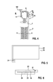
Fig. 2 und 3 mit einem piezokristallinen Resonanzelement auf der Basis einer piezokristallinen Folie, sowie - Fig. 5 und 6
- eine Draufsicht und einen Schnitt durch eine Sandwich-Konstruktion einer piezokristallinen Folie mit Metallschicht zum Einsatz in der Elektrodeneinrichtung gemäß
Fig. 4 . -
Fig. 1 zeigt eine implantierbare Elektrodeneinrichtung mit einem schematisch dargestellten Herzschrittmacher 1, an dessen Header 2 ein langgestreckter Elektrodenkörper 3 mit seinem proximalen Ende 4 angeschlossen ist. Am distalen Ende 5 des Elektrodenkörpers 3 befindet sich eine Tip-Elektrode 6 direkt an der Spitze des Elektrodenkörpers 1 sowie in proximaler Richtung dahinter eine Ringelektrode 7. Derartige Elektrodenanordnungen sind üblich und bedürfen keiner näheren Erläuterung. Im Elektrodenkörper 3 verlaufen die in der Regel wendelförmigen Kontaktleitungen 8 bzw. 9 für die Tip-Elektrode 6 bzw. die Ringelektrode 7. - Die nach Art eines Ersatzschaltbildes ausgeführte
Fig. 1 gibt im Bereich des Headers 2 die kapazitiven und Impedanz-Widerstände CHT, LHT, CHR, LHR zu den Kontaktleitungen 8, 9 sowie die kapazitiven und Ohmschen Widerstände CG, RG zum Elektrodenkörper selbst dar. - Am distalen Ende 5 des Elektrodenkörpers 3 sind die kapazitiven Widerstände CT bzw. CR sowie die Ohmschen Übergangswiderstände RT bzw. RR der Tip- und Ringelektrode 6, 7 dargestellt.
- An die Kontaktleitung 8 der Tip-Elektrode 6 ist nun eine elektromechanische Resonanzeinrichtung 10 angeschlossen, die ein piezokristallines Resonanzelement 11 aufweist. Etwaige in die Kontaktleitung 8 eingestrahlten hochfrequenten Signale regen das Resonanzelement 11 zu mechanischen Schwingungen, also Schallwellen 12, an, die an das Gewebe abgegeben werden. Der Kontakt zwischen elektromechanischer Resonanzeinrichtung 10 und dem Gewebe des Körpers, in dem die Vorrichtung implantiert ist, ist durch die Kapazität CG bzw. den Ohmschen Widerstand RG in Ersatzschaltbild gemäß
Fig. 1 versinnbildlicht. - Bei der in
Fig. 2 gezeigten Ausführungsform weist der Elektrodenkörper 3 die bereits erwähnte Tip- und Ringelektrode 6, 7 am distalen Ende 5 auf. Die elektromechanische Resonanzeinrichtung 10 ist in Form eines hülsenförmigen Piezokristallelements 13 auf die Mantelfläche der Kopfhülse 14 der Tip-Elektrode 6 gesetzt. Die Ringdicke RD des Piezokristallelements 13 beträgt dabei die halbe Wellenlänge der resonanten Druckwellen. Die hohen Schallgeschwindigkeiten innerhalb der kristallinen Keramiken des Piezokristallelements 13 von beispielsweise 10 km/s ergeben bei einer Frequenz von 64 MHz Druck-Wellenlängen um 200 µm Die resonante Schichtdicke und entsprechend die Ringdicke RD des Piezokristallelements 13 liegt dann bei mindestens 100 µm. Die erzeugten Schallwellen 12 werden in den Körper K auf verträgliche Weise abgegebenen. - Bei der in
Fig. 3 gezeigten Anordnung ist das hülsenförmige Piezokristallelement 13 zwischen Tip-Elektrode 6 und Ringelektrode 7 um die wendelförmige Kontaktleitung 8 angeordnet. Über entsprechende Kontaktflächen 15, 16 auf der inneren bzw. äußeren Mantelfläche des hülsenförmigen Piezokristallelements 13 und über Anschlussverbinder 17, 18 erfolgt der elektrische Kontakt mit der Kopfhülse 14 der Tip- bzw. mit der Ringelektrode 6 bzw. 7. Durch diese Konfiguration können jedwede in die Kontaktleitungen 8, 9 eingestrahlten hochfrequenten elektromagnetischen Signale in akustomechanische Wellen umgewandelt und die eingestrahlte Energie körperverträglich dissipiert werden. - Die
Fig. 4 bis 6 stellen eine weitere Ausführungsform des piezokristallinen Resonanzelementes 11 dar, das auf der Basis einer Sandwich-Konstruktion einer metallisierten piezokristallinen Folie realisiert wird. Dazu wird eine piezokristalline Folie 19 auf einer Seite mit einer Metallisierungsbeschichtung 20 versehen, die an einer Stelle mit einer Anschlussfahne 21 versehen ist. Eine zweite Schicht einer piezokristallinen Folie 23 wird auf diese Metallisierungsbeschichtung 20 aufgesetzt. Auf eine der beiden freiliegenden Oberflächen der Folien 19, 22, beispielsweise auf die inFig. 6 obenliegende Fläche der Folie 19, wird eine weitere Metallisierungsbeschichtung 23 aufgebracht. Eine solche Sandwich-Konfiguration wird dann zuerst im Bereich der Anschlussfahne 21 mit der die Tip-Elektrode 6 bildenden Kopfhülse 14 im Bereich deren Mantelfläche verbunden und anschließend die Sandwich-Konstruktion eng um den Kopf gewickelt, so dass die Metallisierungsbeschichtung 23 außen zu liegen kommt und damit den elektrischen Kontakt zum umliegenden Gewebe oder dem Blut im Körper K des Implantatträgers herstellt. Durch die Anzahl der Wicklungen lässt sich der Resonanzeffekt beeinflussen und die Bandbreite der damit erfassbaren Frequenzen eingestrahlter elektromagnetischer Signale den Anforderungen entsprechend anpassen. Die piezokristallinen Folien 19, 22 werden durch physikalische Dampfabscheidung (PVD) hergestellt. - Die Schichtdicke SD der piezokristallinen Folie 19, 22 entspricht wiederum der halben Wellenlänge der durch die Umwandlung eingestrahlter hochfrequenter Signale erzeugten akustomechanischen Schwingungen.
Claims (15)
- Implantierbare Elektrodeneinrichtung, insbesondere für kardiologische Geräte, wie Herzschrittmacher, umfassend- einen lang gestreckten Elektrodenkörper (3) mit einem proximalen (4) und distalen Ende (5),- mindestens einer mit dem Körper des Implantatträgers in Kontakt bringbaren Elektrode (6, 7) am oder in der Nähe des distalen Endes (5) des Elektrodenkörpers (3), und- mindestens eine elektrische Kontaktleitung (8, 9) zur Kontaktierung der Elektrode (6, 7),gekennzeichnet durch- eine an Elektrode (6, 7) oder Kontaktleitung (8, 9) angeschlossene elektromechanische Resonanzeinrichtung (10) zur Umwandlung von in die Elektrodeneinrichtung eingestrahlten hochfrequenten Signale in akustomechanische Schwingungen (12).
- Elektrodeneinrichtung nach Anspruch 1, dadurch gekennzeichnet, dass die elektromechanische Resonanzeinrichtung (10) ein piezokristallines Resonanzelement (11) aufweist.
- Elektrodeneinrichtung nach Anspruch 2, dadurch gekennzeichnet, dass das piezokristalline Resonanzelement (11) eine geometrische Abmessung (RD, SD) aufweist, die der halben Wellenlänge oder einem ungeradzahligen Vielfachen der halben Wellenlänge der akustomechanischen Schwingungen in einem Frequenzbereich von 10 MHz bis 400 MHz entspricht.
- Elektrodeneinrichtung mindestens nach Anspruch 2, dadurch gekennzeichnet, dass das piezokristalline Resonanzelement (11) ein hülsenförmiges Piezokristallelement (13) ist.
- Elektrodeneinrichtung nach Anspruch 4, dadurch gekennzeichnet, dass die Ringdicke (RD) des hülsenförmigen Piezokristallelements (13) der halben Wellenlänge der akustomechanischen Schwingung entspricht.
- Elektrodeneinrichtung mindestens nach Anspruch 2, dadurch gekennzeichnet, dass das piezokristalline Resonanzelement (11) durch eine piezokristalline Folie (19, 22) aus PVDF, Polyvinylidenfluorid, gebildet ist.
- Elektrodeneinrichtung nach Anspruch 6, dadurch gekennzeichnet, dass die piezokristalline Folie (19, 22) mit einer Metallschicht (20, 23) belegt ist.
- Elektrodeneinrichtung nach Anspruch 7, dadurch gekennzeichnet, dass die piezokristalline Folie (19, 22) mit der Metallschicht (20, 23) als Sandwich-Konstruktion mit mindestens zwei sich abwechselnden Folien- und Metallschichten (19, 20, 22, 23) ausgeführt ist.
- Elektrodeneinrichtung nach Anspruch 7 oder 8, dadurch gekennzeichnet, dass die piezokristalline Folie (19, 22) mit der Metallschicht (20, 23) zur Bildung der elektromechanischen Resonanzeinrichtung (10) mehrfach um einen Träger, insbesondere um eine Kopfhülse (14) einer Tipelektrode (6), gewickelt ist.
- Elektrodeneinrichtung nach Anspruch 7 oder 8, dadurch gekennzeichnet, dass die Metallschicht (20) mit einer Anschlussfahne (21) zur Kontaktierung versehen ist.
- Elektrodeneinrichtung nach einem der vorgenannten Ansprüche, dadurch gekennzeichnet, dass die elektromechanische Resonanzeinrichtung (10) schaltungstechnisch zwischen der Elektrode (6) oder ihrer Kontaktleitung (8) und dem Körper (K) des Implantatträgers angeordnet ist.
- Elektrodeneinrichtung nach einem der vorgenannten Ansprüche mit einer Kopfhülse (24) im Bereich der distalen Elektrode (6, 7), dadurch gekennzeichnet, dass die elektromechanische Resonanzeinrichtung (10) außen auf der Kopfhülse (14) oder innen in der Kopfhülse (14) oder innerhalb der Kopfhülse (14) auf einer Welle angebracht oder einen Abschnitt der Kopfhülse (14) bildet.
- Elektrodeneinrichtung nach einem der Ansprüche 1 bis 11, dadurch gekennzeichnet, dass die elektromechanische Resonanzeinrichtung (10) schaltungstechnisch zwischen zwei Elektroden (6, 7) der Elektrodeneinrichtung, insbesondere zwischen einer Tipelektrode (6) und einer Ringelektrode (7) angeordnet ist.
- Elektrodeneinrichtung nach einem der Ansprüche 1 bis 11 mit einer Ringelektrode (7), dadurch gekennzeichnet, dass die elektromechanische Resonanzeinrichtung (10) unter der Ringelektrode (7) angeordnet ist.
- Elektrodeneinrichtung nach einem der vorgenannten Ansprüche, dadurch gekennzeichnet, dass das piezokristallines Resonanzelement (11) ganz oder teilweise aus einem Material ausgewählt aus der folgenden Gruppe besteht: anisotropen SiO2 (α- Quarz Glas), Aluminium-Nitrid, Polyvinylidenfluorid, Barium-Titanat, Lithiumniobate, Galliumorthophosphate, Berlinit, Mineralien der Turmalingruppe, Seignettesal oder Kalium-Natrium-Niobate.
Applications Claiming Priority (1)
| Application Number | Priority Date | Filing Date | Title |
|---|---|---|---|
| US201361908183P | 2013-11-25 | 2013-11-25 |
Publications (2)
| Publication Number | Publication Date |
|---|---|
| EP2875844A1 true EP2875844A1 (de) | 2015-05-27 |
| EP2875844B1 EP2875844B1 (de) | 2018-01-03 |
Family
ID=51743363
Family Applications (1)
| Application Number | Title | Priority Date | Filing Date |
|---|---|---|---|
| EP14189633.2A Not-in-force EP2875844B1 (de) | 2013-11-25 | 2014-10-21 | Implantierbare Elektrodeneinrichtung, insbesondere für kardiologische Geräte, wie Herzschrittmacher |
Country Status (2)
| Country | Link |
|---|---|
| US (1) | US9421364B2 (de) |
| EP (1) | EP2875844B1 (de) |
Cited By (1)
| Publication number | Priority date | Publication date | Assignee | Title |
|---|---|---|---|---|
| EP3170574A1 (de) | 2015-11-19 | 2017-05-24 | Heraeus Deutschland GmbH & Co. KG | Verfahren zur herstellung einer hülse für eine elektrode für medizinische anwendungen |
Families Citing this family (1)
| Publication number | Priority date | Publication date | Assignee | Title |
|---|---|---|---|---|
| DE102019215673B3 (de) | 2019-10-11 | 2021-02-18 | Albert-Ludwigs-Universität Freiburg | Implantierbare Elektrodenanordnung und Herstellungsverfahren |
Citations (10)
| Publication number | Priority date | Publication date | Assignee | Title |
|---|---|---|---|---|
| DE19840211C1 (de) * | 1998-09-03 | 1999-12-30 | Implex Hear Tech Ag | Wandler für teil- oder vollimplantierbare Hörgeräte |
| US20040215279A1 (en) * | 2003-04-25 | 2004-10-28 | Houben Richard P.M. | Implantable lead-based sensor powered by piezoelectric transformer |
| US6871091B2 (en) | 2001-10-31 | 2005-03-22 | Medtronic, Inc. | Apparatus and method for shunting induced currents in an electrical lead |
| US6944489B2 (en) | 2001-10-31 | 2005-09-13 | Medtronic, Inc. | Method and apparatus for shunting induced currents in an electrical lead |
| US20080009905A1 (en) | 2006-06-23 | 2008-01-10 | Zeijlemaker Volkert A | Electrode system with shunt electrode |
| US7363090B2 (en) | 2001-04-13 | 2008-04-22 | Greatbatch Ltd. | Band stop filter employing a capacitor and an inductor tank circuit to enhance MRI compatibility of active implantable medical devices |
| US20110137390A1 (en) * | 2009-12-08 | 2011-06-09 | Hill Gerard J | System and method for protecting implanted medical devices from interfering radiated fields |
| EP2478932A2 (de) * | 2010-12-20 | 2012-07-25 | BIOTRONIK SE & Co. KG | Implantierbares Gerät |
| DE102011086208A1 (de) * | 2011-11-11 | 2013-05-16 | Universität Rostock | Ohrimplantat und Stimulationselektrode für ein Ohrimplantat |
| EP2602001A1 (de) * | 2011-12-08 | 2013-06-12 | BIOTRONIK SE & Co. KG | Medizintechnisches Implantat und medizintechnische Anordnung |
-
2014
- 2014-10-21 EP EP14189633.2A patent/EP2875844B1/de not_active Not-in-force
- 2014-10-30 US US14/529,044 patent/US9421364B2/en not_active Expired - Fee Related
Patent Citations (10)
| Publication number | Priority date | Publication date | Assignee | Title |
|---|---|---|---|---|
| DE19840211C1 (de) * | 1998-09-03 | 1999-12-30 | Implex Hear Tech Ag | Wandler für teil- oder vollimplantierbare Hörgeräte |
| US7363090B2 (en) | 2001-04-13 | 2008-04-22 | Greatbatch Ltd. | Band stop filter employing a capacitor and an inductor tank circuit to enhance MRI compatibility of active implantable medical devices |
| US6871091B2 (en) | 2001-10-31 | 2005-03-22 | Medtronic, Inc. | Apparatus and method for shunting induced currents in an electrical lead |
| US6944489B2 (en) | 2001-10-31 | 2005-09-13 | Medtronic, Inc. | Method and apparatus for shunting induced currents in an electrical lead |
| US20040215279A1 (en) * | 2003-04-25 | 2004-10-28 | Houben Richard P.M. | Implantable lead-based sensor powered by piezoelectric transformer |
| US20080009905A1 (en) | 2006-06-23 | 2008-01-10 | Zeijlemaker Volkert A | Electrode system with shunt electrode |
| US20110137390A1 (en) * | 2009-12-08 | 2011-06-09 | Hill Gerard J | System and method for protecting implanted medical devices from interfering radiated fields |
| EP2478932A2 (de) * | 2010-12-20 | 2012-07-25 | BIOTRONIK SE & Co. KG | Implantierbares Gerät |
| DE102011086208A1 (de) * | 2011-11-11 | 2013-05-16 | Universität Rostock | Ohrimplantat und Stimulationselektrode für ein Ohrimplantat |
| EP2602001A1 (de) * | 2011-12-08 | 2013-06-12 | BIOTRONIK SE & Co. KG | Medizintechnisches Implantat und medizintechnische Anordnung |
Cited By (2)
| Publication number | Priority date | Publication date | Assignee | Title |
|---|---|---|---|---|
| EP3170574A1 (de) | 2015-11-19 | 2017-05-24 | Heraeus Deutschland GmbH & Co. KG | Verfahren zur herstellung einer hülse für eine elektrode für medizinische anwendungen |
| US11161165B2 (en) | 2015-11-19 | 2021-11-02 | Heraeus Deutschland GmbH & Co. KG | Processes for producing a sleeve for an electrode for medical applications |
Also Published As
| Publication number | Publication date |
|---|---|
| US20150148879A1 (en) | 2015-05-28 |
| EP2875844B1 (de) | 2018-01-03 |
| US9421364B2 (en) | 2016-08-23 |
Similar Documents
| Publication | Publication Date | Title |
|---|---|---|
| DE4010294C2 (de) | ||
| DE102013201928A1 (de) | Schallwandlertechnik | |
| EP1923094B1 (de) | Elektrodenkatheter zu Interventionszwecken | |
| EP2359896B1 (de) | Elektrodenvorrichtung zur Strom- oder Spannungsführung zwischen einem implantierbaren elektromedizinischen Gerät und einem Therapie- und/oder Diagnoseort im menschlichen Körper | |
| EP1923095B1 (de) | Elektrode zu Interventionszwecken | |
| DE112007002645T5 (de) | Ultraschallsonde | |
| EP2465572B1 (de) | MRT-kompatible implantierbare Leitung | |
| EP2875844B1 (de) | Implantierbare Elektrodeneinrichtung, insbesondere für kardiologische Geräte, wie Herzschrittmacher | |
| EP0118837B1 (de) | Ultraschallwandler | |
| DE102020100121A1 (de) | Implantierbare Elektrode mit einer Stichleitung | |
| DE102005030745B4 (de) | HF-Spulen für Kernspintomographen | |
| WO2014124800A1 (de) | Elektrisches übertragerbauelement | |
| DE102014102157A1 (de) | Vorrichtung für die ultraschallgestützte Reflexions- und Transmissions-Tomographie | |
| EP2359899B1 (de) | Elektrodenvorrichtung für aktive medizinische Implantate | |
| EP1741162B1 (de) | Elektrische funktionseinheit und verfahren zu deren herstellung | |
| DE102012105647A1 (de) | Aus einer Spule und einem daran angeschlossenen Piezoelement kombiniertes elektrisches Element | |
| EP3217576B1 (de) | Implantat und verfahren zum betreiben desselben | |
| EP2848282B1 (de) | Implantierbares Gerät | |
| EP2054951B1 (de) | Piezoelektrisches bauelement | |
| EP2283894B1 (de) | Stimulationselektrodenleitung | |
| EP2853288B1 (de) | Implantierbares Gerät und Herstellungsverfahren für ein implantierbares Gerät | |
| EP2985054B1 (de) | Implantierbares gerät mit elektrischem filter | |
| DE102019107600B4 (de) | Antennenanordnung | |
| EP3668590B1 (de) | Isolation einer passivierung | |
| EP3620209A1 (de) | Passiver sensor zur drahtlosen detektion der elektrischen erregung von muskelzellen |
Legal Events
| Date | Code | Title | Description |
|---|---|---|---|
| PUAI | Public reference made under article 153(3) epc to a published international application that has entered the european phase |
Free format text: ORIGINAL CODE: 0009012 |
|
| 17P | Request for examination filed |
Effective date: 20141021 |
|
| AK | Designated contracting states |
Kind code of ref document: A1 Designated state(s): AL AT BE BG CH CY CZ DE DK EE ES FI FR GB GR HR HU IE IS IT LI LT LU LV MC MK MT NL NO PL PT RO RS SE SI SK SM TR |
|
| AX | Request for extension of the european patent |
Extension state: BA ME |
|
| R17P | Request for examination filed (corrected) |
Effective date: 20151126 |
|
| RBV | Designated contracting states (corrected) |
Designated state(s): AL AT BE BG CH CY CZ DE DK EE ES FI FR GB GR HR HU IE IS IT LI LT LU LV MC MK MT NL NO PL PT RO RS SE SI SK SM TR |
|
| 17Q | First examination report despatched |
Effective date: 20161122 |
|
| GRAP | Despatch of communication of intention to grant a patent |
Free format text: ORIGINAL CODE: EPIDOSNIGR1 |
|
| INTG | Intention to grant announced |
Effective date: 20170725 |
|
| GRAS | Grant fee paid |
Free format text: ORIGINAL CODE: EPIDOSNIGR3 |
|
| GRAA | (expected) grant |
Free format text: ORIGINAL CODE: 0009210 |
|
| AK | Designated contracting states |
Kind code of ref document: B1 Designated state(s): AL AT BE BG CH CY CZ DE DK EE ES FI FR GB GR HR HU IE IS IT LI LT LU LV MC MK MT NL NO PL PT RO RS SE SI SK SM TR |
|
| REG | Reference to a national code |
Ref country code: GB Ref legal event code: FG4D Free format text: NOT ENGLISH |
|
| REG | Reference to a national code |
Ref country code: CH Ref legal event code: EP Ref country code: AT Ref legal event code: REF Ref document number: 959674 Country of ref document: AT Kind code of ref document: T Effective date: 20180115 |
|
| REG | Reference to a national code |
Ref country code: IE Ref legal event code: FG4D Free format text: LANGUAGE OF EP DOCUMENT: GERMAN |
|
| REG | Reference to a national code |
Ref country code: DE Ref legal event code: R096 Ref document number: 502014006790 Country of ref document: DE |
|
| REG | Reference to a national code |
Ref country code: NL Ref legal event code: MP Effective date: 20180103 |
|
| REG | Reference to a national code |
Ref country code: LT Ref legal event code: MG4D |
|
| PG25 | Lapsed in a contracting state [announced via postgrant information from national office to epo] |
Ref country code: NL Free format text: LAPSE BECAUSE OF FAILURE TO SUBMIT A TRANSLATION OF THE DESCRIPTION OR TO PAY THE FEE WITHIN THE PRESCRIBED TIME-LIMIT Effective date: 20180103 |
|
| PG25 | Lapsed in a contracting state [announced via postgrant information from national office to epo] |
Ref country code: CY Free format text: LAPSE BECAUSE OF FAILURE TO SUBMIT A TRANSLATION OF THE DESCRIPTION OR TO PAY THE FEE WITHIN THE PRESCRIBED TIME-LIMIT Effective date: 20180103 Ref country code: HR Free format text: LAPSE BECAUSE OF FAILURE TO SUBMIT A TRANSLATION OF THE DESCRIPTION OR TO PAY THE FEE WITHIN THE PRESCRIBED TIME-LIMIT Effective date: 20180103 Ref country code: NO Free format text: LAPSE BECAUSE OF FAILURE TO SUBMIT A TRANSLATION OF THE DESCRIPTION OR TO PAY THE FEE WITHIN THE PRESCRIBED TIME-LIMIT Effective date: 20180403 Ref country code: FI Free format text: LAPSE BECAUSE OF FAILURE TO SUBMIT A TRANSLATION OF THE DESCRIPTION OR TO PAY THE FEE WITHIN THE PRESCRIBED TIME-LIMIT Effective date: 20180103 Ref country code: LT Free format text: LAPSE BECAUSE OF FAILURE TO SUBMIT A TRANSLATION OF THE DESCRIPTION OR TO PAY THE FEE WITHIN THE PRESCRIBED TIME-LIMIT Effective date: 20180103 Ref country code: ES Free format text: LAPSE BECAUSE OF FAILURE TO SUBMIT A TRANSLATION OF THE DESCRIPTION OR TO PAY THE FEE WITHIN THE PRESCRIBED TIME-LIMIT Effective date: 20180103 |
|
| PG25 | Lapsed in a contracting state [announced via postgrant information from national office to epo] |
Ref country code: LV Free format text: LAPSE BECAUSE OF FAILURE TO SUBMIT A TRANSLATION OF THE DESCRIPTION OR TO PAY THE FEE WITHIN THE PRESCRIBED TIME-LIMIT Effective date: 20180103 Ref country code: SE Free format text: LAPSE BECAUSE OF FAILURE TO SUBMIT A TRANSLATION OF THE DESCRIPTION OR TO PAY THE FEE WITHIN THE PRESCRIBED TIME-LIMIT Effective date: 20180103 Ref country code: RS Free format text: LAPSE BECAUSE OF FAILURE TO SUBMIT A TRANSLATION OF THE DESCRIPTION OR TO PAY THE FEE WITHIN THE PRESCRIBED TIME-LIMIT Effective date: 20180103 Ref country code: BG Free format text: LAPSE BECAUSE OF FAILURE TO SUBMIT A TRANSLATION OF THE DESCRIPTION OR TO PAY THE FEE WITHIN THE PRESCRIBED TIME-LIMIT Effective date: 20180403 Ref country code: IS Free format text: LAPSE BECAUSE OF FAILURE TO SUBMIT A TRANSLATION OF THE DESCRIPTION OR TO PAY THE FEE WITHIN THE PRESCRIBED TIME-LIMIT Effective date: 20180503 Ref country code: GR Free format text: LAPSE BECAUSE OF FAILURE TO SUBMIT A TRANSLATION OF THE DESCRIPTION OR TO PAY THE FEE WITHIN THE PRESCRIBED TIME-LIMIT Effective date: 20180404 Ref country code: PL Free format text: LAPSE BECAUSE OF FAILURE TO SUBMIT A TRANSLATION OF THE DESCRIPTION OR TO PAY THE FEE WITHIN THE PRESCRIBED TIME-LIMIT Effective date: 20180103 |
|
| PG25 | Lapsed in a contracting state [announced via postgrant information from national office to epo] |
Ref country code: MT Free format text: LAPSE BECAUSE OF FAILURE TO SUBMIT A TRANSLATION OF THE DESCRIPTION OR TO PAY THE FEE WITHIN THE PRESCRIBED TIME-LIMIT Effective date: 20180103 |
|
| REG | Reference to a national code |
Ref country code: DE Ref legal event code: R097 Ref document number: 502014006790 Country of ref document: DE |
|
| PG25 | Lapsed in a contracting state [announced via postgrant information from national office to epo] |
Ref country code: AL Free format text: LAPSE BECAUSE OF FAILURE TO SUBMIT A TRANSLATION OF THE DESCRIPTION OR TO PAY THE FEE WITHIN THE PRESCRIBED TIME-LIMIT Effective date: 20180103 Ref country code: RO Free format text: LAPSE BECAUSE OF FAILURE TO SUBMIT A TRANSLATION OF THE DESCRIPTION OR TO PAY THE FEE WITHIN THE PRESCRIBED TIME-LIMIT Effective date: 20180103 Ref country code: IT Free format text: LAPSE BECAUSE OF FAILURE TO SUBMIT A TRANSLATION OF THE DESCRIPTION OR TO PAY THE FEE WITHIN THE PRESCRIBED TIME-LIMIT Effective date: 20180103 Ref country code: EE Free format text: LAPSE BECAUSE OF FAILURE TO SUBMIT A TRANSLATION OF THE DESCRIPTION OR TO PAY THE FEE WITHIN THE PRESCRIBED TIME-LIMIT Effective date: 20180103 |
|
| PLBE | No opposition filed within time limit |
Free format text: ORIGINAL CODE: 0009261 |
|
| STAA | Information on the status of an ep patent application or granted ep patent |
Free format text: STATUS: NO OPPOSITION FILED WITHIN TIME LIMIT |
|
| PG25 | Lapsed in a contracting state [announced via postgrant information from national office to epo] |
Ref country code: SM Free format text: LAPSE BECAUSE OF FAILURE TO SUBMIT A TRANSLATION OF THE DESCRIPTION OR TO PAY THE FEE WITHIN THE PRESCRIBED TIME-LIMIT Effective date: 20180103 Ref country code: SK Free format text: LAPSE BECAUSE OF FAILURE TO SUBMIT A TRANSLATION OF THE DESCRIPTION OR TO PAY THE FEE WITHIN THE PRESCRIBED TIME-LIMIT Effective date: 20180103 Ref country code: DK Free format text: LAPSE BECAUSE OF FAILURE TO SUBMIT A TRANSLATION OF THE DESCRIPTION OR TO PAY THE FEE WITHIN THE PRESCRIBED TIME-LIMIT Effective date: 20180103 Ref country code: CZ Free format text: LAPSE BECAUSE OF FAILURE TO SUBMIT A TRANSLATION OF THE DESCRIPTION OR TO PAY THE FEE WITHIN THE PRESCRIBED TIME-LIMIT Effective date: 20180103 |
|
| 26N | No opposition filed |
Effective date: 20181005 |
|
| PG25 | Lapsed in a contracting state [announced via postgrant information from national office to epo] |
Ref country code: SI Free format text: LAPSE BECAUSE OF FAILURE TO SUBMIT A TRANSLATION OF THE DESCRIPTION OR TO PAY THE FEE WITHIN THE PRESCRIBED TIME-LIMIT Effective date: 20180103 |
|
| REG | Reference to a national code |
Ref country code: DE Ref legal event code: R119 Ref document number: 502014006790 Country of ref document: DE |
|
| REG | Reference to a national code |
Ref country code: CH Ref legal event code: PL |
|
| GBPC | Gb: european patent ceased through non-payment of renewal fee |
Effective date: 20181021 |
|
| REG | Reference to a national code |
Ref country code: BE Ref legal event code: MM Effective date: 20181031 |
|
| PG25 | Lapsed in a contracting state [announced via postgrant information from national office to epo] |
Ref country code: MC Free format text: LAPSE BECAUSE OF FAILURE TO SUBMIT A TRANSLATION OF THE DESCRIPTION OR TO PAY THE FEE WITHIN THE PRESCRIBED TIME-LIMIT Effective date: 20180103 Ref country code: LU Free format text: LAPSE BECAUSE OF NON-PAYMENT OF DUE FEES Effective date: 20181021 |
|
| REG | Reference to a national code |
Ref country code: IE Ref legal event code: MM4A |
|
| PG25 | Lapsed in a contracting state [announced via postgrant information from national office to epo] |
Ref country code: DE Free format text: LAPSE BECAUSE OF NON-PAYMENT OF DUE FEES Effective date: 20190501 |
|
| PG25 | Lapsed in a contracting state [announced via postgrant information from national office to epo] |
Ref country code: CH Free format text: LAPSE BECAUSE OF NON-PAYMENT OF DUE FEES Effective date: 20181031 Ref country code: FR Free format text: LAPSE BECAUSE OF NON-PAYMENT OF DUE FEES Effective date: 20181031 Ref country code: BE Free format text: LAPSE BECAUSE OF NON-PAYMENT OF DUE FEES Effective date: 20181031 Ref country code: LI Free format text: LAPSE BECAUSE OF NON-PAYMENT OF DUE FEES Effective date: 20181031 |
|
| PG25 | Lapsed in a contracting state [announced via postgrant information from national office to epo] |
Ref country code: IE Free format text: LAPSE BECAUSE OF NON-PAYMENT OF DUE FEES Effective date: 20181021 Ref country code: GB Free format text: LAPSE BECAUSE OF NON-PAYMENT OF DUE FEES Effective date: 20181021 |
|
| PG25 | Lapsed in a contracting state [announced via postgrant information from national office to epo] |
Ref country code: TR Free format text: LAPSE BECAUSE OF FAILURE TO SUBMIT A TRANSLATION OF THE DESCRIPTION OR TO PAY THE FEE WITHIN THE PRESCRIBED TIME-LIMIT Effective date: 20180103 |
|
| PG25 | Lapsed in a contracting state [announced via postgrant information from national office to epo] |
Ref country code: PT Free format text: LAPSE BECAUSE OF FAILURE TO SUBMIT A TRANSLATION OF THE DESCRIPTION OR TO PAY THE FEE WITHIN THE PRESCRIBED TIME-LIMIT Effective date: 20180103 |
|
| PG25 | Lapsed in a contracting state [announced via postgrant information from national office to epo] |
Ref country code: HU Free format text: LAPSE BECAUSE OF FAILURE TO SUBMIT A TRANSLATION OF THE DESCRIPTION OR TO PAY THE FEE WITHIN THE PRESCRIBED TIME-LIMIT; INVALID AB INITIO Effective date: 20141021 Ref country code: MK Free format text: LAPSE BECAUSE OF NON-PAYMENT OF DUE FEES Effective date: 20180103 |
|
| REG | Reference to a national code |
Ref country code: AT Ref legal event code: MM01 Ref document number: 959674 Country of ref document: AT Kind code of ref document: T Effective date: 20191021 |
|
| PG25 | Lapsed in a contracting state [announced via postgrant information from national office to epo] |
Ref country code: AT Free format text: LAPSE BECAUSE OF NON-PAYMENT OF DUE FEES Effective date: 20191021 |