EP2875712B1 - Lawnmower battery arrangement - Google Patents
Lawnmower battery arrangement Download PDFInfo
- Publication number
- EP2875712B1 EP2875712B1 EP13193819.3A EP13193819A EP2875712B1 EP 2875712 B1 EP2875712 B1 EP 2875712B1 EP 13193819 A EP13193819 A EP 13193819A EP 2875712 B1 EP2875712 B1 EP 2875712B1
- Authority
- EP
- European Patent Office
- Prior art keywords
- lawnmower
- battery
- batteries
- platform
- motor
- Prior art date
- Legal status (The legal status is an assumption and is not a legal conclusion. Google has not performed a legal analysis and makes no representation as to the accuracy of the status listed.)
- Active
Links
Images



Classifications
-
- A—HUMAN NECESSITIES
- A01—AGRICULTURE; FORESTRY; ANIMAL HUSBANDRY; HUNTING; TRAPPING; FISHING
- A01D—HARVESTING; MOWING
- A01D34/00—Mowers; Mowing apparatus of harvesters
- A01D34/01—Mowers; Mowing apparatus of harvesters characterised by features relating to the type of cutting apparatus
- A01D34/412—Mowers; Mowing apparatus of harvesters characterised by features relating to the type of cutting apparatus having rotating cutters
- A01D34/63—Mowers; Mowing apparatus of harvesters characterised by features relating to the type of cutting apparatus having rotating cutters having cutters rotating about a vertical axis
- A01D34/76—Driving mechanisms for the cutters
- A01D34/78—Driving mechanisms for the cutters electric
-
- A—HUMAN NECESSITIES
- A01—AGRICULTURE; FORESTRY; ANIMAL HUSBANDRY; HUNTING; TRAPPING; FISHING
- A01D—HARVESTING; MOWING
- A01D69/00—Driving mechanisms or parts thereof for harvesters or mowers
- A01D69/02—Driving mechanisms or parts thereof for harvesters or mowers electric
Definitions
- the present invention relates to a battery-powered lawnmower and in particular to a lawnmower with at least two batteries.
- EP-A-1285567 represents the closest prior art and discloses a lawnmower having the features of the preamble of claim 1.
- a lawnmower comprising a chassis including a cutting chamber, a cutting blade rotatably mounted within the cutting chamber, and an electric motor mounted to the chassis above the cutting chamber which in use drives the cutting blade, wherein the electric motor is powered by at least two batteries which are spaced from one another to provide an air gap in between and wherein the batteries are mounted on a platform above the motor, a substantial proportion of the underside of the platform being open to air, characterised in that a pair of electrical terminals for connection with each battery are provided on the platform, separated by a substantially horizontal surface which includes a drainage aperture.
- a cover is typically provided over the major components on a lawnmower chassis.
- the cover not only protects components and may improve the overall aesthetics of the product, but it also prevents the user accidentally or deliberately touching dangerous parts such as the cutting blade, drive belts, hot components such as the exhaust, or electrical components.
- An advantageous feature of the present invention is that a cover is not necessary and the major components (motor, batteries, electronics housing) are uncovered in use and open to air. This improves access for cleaning, repair or servicing and also improves cooling of components such as the batteries, motor and electronics. It also saves the cost of the cover, which is a relatively bulky component.
- the major components have however been designed such that no danger is presented to the operator by the absence of a cover.
- each battery is substantially uncovered and open to air when installed on the lawnmower.
- the batteries are preferably substantially cuboid in shape, and may be rectangular or square cuboid in shape.
- at least three faces of each battery are uncovered and open to air in use.
- four faces of each battery are uncovered and open to air when installed on the lawnmower.
- the batteries are mounted on a platform above the motor and a substantial proportion of the underside of the platform is open to air. By spacing the batteries from the motor, cooling for the batteries and the motor can be improved.
- An electronics housing may also be mounted on the platform, adjacent to the batteries.
- the platform may be mounted to the motor by means of a plurality of mounting posts which space the platform from the motor and allow air to circulate in between.
- one or more drainage apertures are provided on the platform to ensure that any water which collects is allowed to drain out.
- a pair of electrical terminals for connection with the battery are provided on the platform, separated by a substantially horizontal surface which includes the drainage aperture.
- the drainage aperture is preferably at least as long as the length of each terminal side which faces the other.
- the batteries may be located at any suitable place and with any suitable orientation, the batteries are preferably mounted side by side, in a transverse direction across the lawnmower. The air gap will therefore run longitudinally.
- the batteries are preferably mounted with their transverse centrelines forward of the axis of the motor. They may be mounted entirely forward of the axis of the motor.
- each battery is rechargeable and is removable from the lawnmower.
- the batteries may slide onto the platform, and this may be most convenient from the front of the lawnmower.
- Each battery may be retained in a docked position on the lawnmower by means of a latch mechanism.
- the latch mechanism is movable from a latched position to an open position and includes a projection which, in the latched position, engages with the battery to retain the battery in the docked position.
- the latch mechanism is biased towards the latched position and is movable towards the open position against the latch biasing force.
- each battery is urged away from the docked position by a battery biasing force.
- the latch mechanism when in the latched position, retains the battery in the docked position against the battery biasing force.
- the battery biasing force is provided by a spring within the battery which acts against the lawnmower to cause them to separate in the absence of the latch retaining force.
- the lawnmower of the present invention may include an isolator key which, when removed from the lawnmower, electrically isolates the batteries from the motor.
- the batteries may be similar to those commonly used for hand-held power tools.
- the batteries have an air gap in between so that both sides of each battery are able to cool to atmosphere. Extra cooling is achieved by airflow to the platform directly underneath.
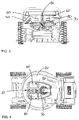
- a lawnmower 10 is shown.
- the main lawnmower components relevant to the invention are chassis 20, electric motor 30, platform 40, electronics housing 50 and batteries 60.
- Chassis 20 defines a cutting chamber 21 within which a cutting blade (not shown) is rotatably mounted.
- Motor 30 is mounted to the chassis directly above the cutting chamber and drives the cutting blade within the cutting chamber in use.
- Platform 40 is mounted onto the motor 30 by means of four pillars 41. These serve to space the platform from the motor and to promote airflow around and between these components.
- An electronics housing 50 is provided on top of platform 40 and two rectangular batteries 60 are mounted with their elongate axes parallel with the longitudinal axis of the lawnmower. They are mounted in a side-by-side configuration and are separated by an air gap 61. The batteries are held in place by a latch mechanism 70 which is described in further detail below and an isolator key 80 is also provided.
- Fig. 6 shows a perspective exploded view of the platform 40 and electronics housing 50.
- Electronic components 51 are mounted on platform 40 and are covered by the housing 50.
- the forward part of platform 40 and electronics housing 50 combine to form docking bays 42 for each battery.
- Each battery 60 slides into its respective docking bay 42 from the front of the lawnmower.
- Latch mechanism 70 comprises arm 71 which is able to pivot about point P between a latched and an open position.
- the latch arm 71 is biased towards the latched position (i.e. biased in an anti-clockwise direction) by means of spring 72.
- Latch arm 71 has a triangular latch projection 73 which engages with a corresponding recess 63 in battery 60 when the battery is docked and retains the battery in that position.
- the battery underside pushes latch projection downwards against the biasing force of spring 72 until the point at which battery recess 63 lines up with latch projection 73.
- Latch arm 71 will then snap into engagement with the battery under the spring biasing force and retain it in the docked position.
- the battery is fitted with a spring 64 which provides a biasing force against the platform 40 to urge the battery away from the docked position, in a direction towards the front of the lawnmower.
- the latch mechanism 70 retains the battery in that position against the battery biasing force provided by spring 64.
- spring 64 pushes the battery towards the front of the lawnmower (to the left in the figure) so that the electrical connections are broken. The battery can then be removed by continuing to slide it forwards and out of the docking bay 42.
- Figs. 8A and 8B show the electrical contacts 43 on platform 40, with which the battery makes connection when docked.
- the positive and negative connections are arranged either side of a central sensor/data connection, through which information such as state of charge, cell temperature, etc. is communicated to the electronic control.
- a substantially horizontal surface 44 connects between each pair of vertically-oriented terminals 43. This surface is interrupted by a drainage slot 45 so that any water collecting in this area drains through into the mounting lugs 46 below.
- Each drainage slot is preferably at least 3mm wide and preferably at least as long as the length of each terminal side which faces the other.
Landscapes
- Life Sciences & Earth Sciences (AREA)
- Environmental Sciences (AREA)
- Harvester Elements (AREA)
- Battery Mounting, Suspending (AREA)
Description
- The present invention relates to a battery-powered lawnmower and in particular to a lawnmower with at least two batteries.
- In normal operating conditions, professional petrol lawnmowers typically have a run time on one fuel tank of 1 to 1.25 hours. A battery-powered lawnmower aimed at the professional market would therefore need to have a similar run time before the battery needs to be recharged or replaced with a fully-charged battery. Whilst batteries exist with sufficient capacity to run a lawnmower for a similar time, current battery technology is such that a suitable battery would be large, heavy and expensive. In addition, technical issues could arise due to insufficient cooling and subsequent restriction in usage cycles.
-
EP-A-1285567 represents the closest prior art and discloses a lawnmower having the features of the preamble of claim 1. - In accordance with the invention, there is provided a lawnmower comprising a chassis including a cutting chamber, a cutting blade rotatably mounted within the cutting chamber, and an electric motor mounted to the chassis above the cutting chamber which in use drives the cutting blade, wherein the electric motor is powered by at least two batteries which are spaced from one another to provide an air gap in between and wherein the batteries are mounted on a platform above the motor, a substantial proportion of the underside of the platform being open to air, characterised in that a pair of electrical terminals for connection with each battery are provided on the platform, separated by a substantially horizontal surface which includes a drainage aperture.
- A cover is typically provided over the major components on a lawnmower chassis. The cover not only protects components and may improve the overall aesthetics of the product, but it also prevents the user accidentally or deliberately touching dangerous parts such as the cutting blade, drive belts, hot components such as the exhaust, or electrical components.
- An advantageous feature of the present invention is that a cover is not necessary and the major components (motor, batteries, electronics housing) are uncovered in use and open to air. This improves access for cleaning, repair or servicing and also improves cooling of components such as the batteries, motor and electronics. It also saves the cost of the cover, which is a relatively bulky component. The major components have however been designed such that no danger is presented to the operator by the absence of a cover.
- Preferably therefore, the top surface each battery is substantially uncovered and open to air when installed on the lawnmower. The batteries are preferably substantially cuboid in shape, and may be rectangular or square cuboid in shape. When in this form, preferably at least three faces of each battery are uncovered and open to air in use. In a particularly preferred arrangement, four faces of each battery are uncovered and open to air when installed on the lawnmower.
- In accordance with the invention, the batteries are mounted on a platform above the motor and a substantial proportion of the underside of the platform is open to air. By spacing the batteries from the motor, cooling for the batteries and the motor can be improved. An electronics housing may also be mounted on the platform, adjacent to the batteries. The platform may be mounted to the motor by means of a plurality of mounting posts which space the platform from the motor and allow air to circulate in between.
- A particular problem arises from the batteries being uncovered when mounted on the lawnmower, in respect of water resistance. The product must be designed so that it can be used in wet conditions and even left out in such conditions, with or without either or both batteries in place. Therefore, it is important that any water falling on the lawnmower cannot form a continuous bridge between the battery connections to the lawnmower. In accordance with the invention, one or more drainage apertures are provided on the platform to ensure that any water which collects is allowed to drain out. A pair of electrical terminals for connection with the battery are provided on the platform, separated by a substantially horizontal surface which includes the drainage aperture. The drainage aperture is preferably at least as long as the length of each terminal side which faces the other.
- While the batteries may be located at any suitable place and with any suitable orientation, the batteries are preferably mounted side by side, in a transverse direction across the lawnmower. The air gap will therefore run longitudinally.
- In order to balance the lawnmower, the batteries are preferably mounted with their transverse centrelines forward of the axis of the motor. They may be mounted entirely forward of the axis of the motor.
- Preferably, each battery is rechargeable and is removable from the lawnmower. The batteries may slide onto the platform, and this may be most convenient from the front of the lawnmower. Each battery may be retained in a docked position on the lawnmower by means of a latch mechanism. In a preferred arrangement, the latch mechanism is movable from a latched position to an open position and includes a projection which, in the latched position, engages with the battery to retain the battery in the docked position. Preferably the latch mechanism is biased towards the latched position and is movable towards the open position against the latch biasing force.
- In a further preferred arrangement, each battery is urged away from the docked position by a battery biasing force. The latch mechanism, when in the latched position, retains the battery in the docked position against the battery biasing force. Preferably, the battery biasing force is provided by a spring within the battery which acts against the lawnmower to cause them to separate in the absence of the latch retaining force.
- The lawnmower of the present invention may include an isolator key which, when removed from the lawnmower, electrically isolates the batteries from the motor.
- Through the provision of at least two batteries which are individually smaller than a single battery of the combined capacity, a run time equivalent to that of a petrol lawnmower can be achieved. The batteries may be similar to those commonly used for hand-held power tools. Through appropriate siting of the batteries, the balance of the product and the weight distribution through the wheels may be optimised. The batteries have an air gap in between so that both sides of each battery are able to cool to atmosphere. Extra cooling is achieved by airflow to the platform directly underneath.
- An embodiment of the invention will now be described by way of example only and with reference to the accompanying drawings, in which:
-
Fig. 1 shows a perspective view of a lawnmower in accordance with the invention; -
Fig. 2 shows a left side elevation of the lawnmower ofFig. 1 ; -
Fig. 3 shows a front elevation of the lawnmower ofFig. 1 ; -
Fig. 4 shows a plan view of the lawnmower ofFig. 1 ; -
Fig. 5 shows a perspective exploded view of the lawnmower ofFig. 1 ; -
Fig. 6 shows a perspective exploded view of the platform and electronics housing; -
Fig. 7 shows a cross-sectional view of the battery, electronics housing, platform and latching mechanism; and -
Figs. 8A and 8B show details of the drainage holes provided in the platform. - With reference to
Figs. 1 to 5 , alawnmower 10 is shown. The main lawnmower components relevant to the invention arechassis 20,electric motor 30,platform 40,electronics housing 50 andbatteries 60. -
Chassis 20 defines acutting chamber 21 within which a cutting blade (not shown) is rotatably mounted.Motor 30 is mounted to the chassis directly above the cutting chamber and drives the cutting blade within the cutting chamber in use. -
Platform 40 is mounted onto themotor 30 by means of fourpillars 41. These serve to space the platform from the motor and to promote airflow around and between these components. - An
electronics housing 50 is provided on top ofplatform 40 and tworectangular batteries 60 are mounted with their elongate axes parallel with the longitudinal axis of the lawnmower. They are mounted in a side-by-side configuration and are separated by anair gap 61. The batteries are held in place by alatch mechanism 70 which is described in further detail below and anisolator key 80 is also provided. -
Fig. 6 shows a perspective exploded view of theplatform 40 andelectronics housing 50.Electronic components 51 are mounted onplatform 40 and are covered by thehousing 50. The forward part ofplatform 40 andelectronics housing 50 combine to formdocking bays 42 for each battery. Eachbattery 60 slides into itsrespective docking bay 42 from the front of the lawnmower. - The battery docking and latching arrangement is shown in more detail in
Fig. 7 .Latch mechanism 70 comprisesarm 71 which is able to pivot about point P between a latched and an open position. Thelatch arm 71 is biased towards the latched position (i.e. biased in an anti-clockwise direction) by means ofspring 72.Latch arm 71 has atriangular latch projection 73 which engages with acorresponding recess 63 inbattery 60 when the battery is docked and retains the battery in that position. When a battery is being inserted, the battery underside pushes latch projection downwards against the biasing force ofspring 72 until the point at whichbattery recess 63 lines up withlatch projection 73.Latch arm 71 will then snap into engagement with the battery under the spring biasing force and retain it in the docked position. - The battery is fitted with a
spring 64 which provides a biasing force against theplatform 40 to urge the battery away from the docked position, in a direction towards the front of the lawnmower. When the battery is in the docked position, thelatch mechanism 70 retains the battery in that position against the battery biasing force provided byspring 64. When thelatch mechanism 70 is released,spring 64 pushes the battery towards the front of the lawnmower (to the left in the figure) so that the electrical connections are broken. The battery can then be removed by continuing to slide it forwards and out of thedocking bay 42. -
Figs. 8A and 8B show theelectrical contacts 43 onplatform 40, with which the battery makes connection when docked. In order to prevent any water landing on the lawnmower making a continuous bridge between the contacts, the positive and negative connections are arranged either side of a central sensor/data connection, through which information such as state of charge, cell temperature, etc. is communicated to the electronic control. A substantiallyhorizontal surface 44 connects between each pair of vertically-orientedterminals 43. This surface is interrupted by adrainage slot 45 so that any water collecting in this area drains through into the mounting lugs 46 below. Each drainage slot is preferably at least 3mm wide and preferably at least as long as the length of each terminal side which faces the other.
Claims (12)
- A lawnmower (10) comprising a chassis (20) including a cutting chamber (21), a cutting blade rotatably mounted within the cutting chamber, and an electric motor (30) mounted to the chassis above the cutting chamber which in use drives the cutting blade, wherein the electric motor (30) is powered by at least two batteries (60) which are spaced from one another to provide an air gap (61) in between and wherein the batteries (60) are mounted on a platform (40) above the motor, a substantial proportion of the underside of the platform being open to air, characterised in that a pair of electrical terminals (43) for connection with each battery (60) are provided on the platform, separated by a substantially horizontal surface (44) which includes a drainage aperture (45).
- The lawnmower of claim 1, in which the top surface of each battery (60) is substantially uncovered in use and open to air.
- The lawnmower of claim 1 or 2, in which the batteries (60) are substantially cuboid in shape and in which at least three faces of each battery are uncovered and open to air in use.
- The lawnmower of any preceding claim, in which an electronics housing (50) is mounted on the platform (40), adjacent to the batteries (60).
- The lawnmower of any preceding claim, in which the platform (40) is mounted to the motor (30) by means of a plurality of mounting posts (41) which space the platform from the motor and allow air to circulate in between.
- The lawnmower of any preceding claim, in which the drainage aperture (45) is at least as long as the length of each terminal side which faces the other.
- The lawnmower of any preceding claim, in which the batteries (60) are mounted side by side, in a transverse direction across the lawnmower.
- The lawnmower of any preceding claim, in which the batteries (60) are mounted forward of the axis of the motor.
- The lawnmower of any preceding claim, in which the batteries (60) are rechargeable and are removable from the lawnmower.
- The lawnmower of claim 9, in which each battery (60) is retained in a docked position on the lawnmower by means of a latch mechanism (70).
- The lawnmower of claim 10, in which the latch mechanism (70) is movable from a latched position to an open position and includes a projection (73) which, in the latched position, engages with the battery (60) to retain the battery in the docked position, the latch mechanism (73) being biased towards the latched position and movable towards the open position against the latch biasing force.
- The lawnmower of claim 10 or 11, in which each battery (60) is urged away from the docked position by a battery biasing force provided by a spring (64) within the battery which acts against the lawnmower to cause them to separate, and in which the latch mechanism (70), when in the latched position, retains the battery in the docked position against the battery biasing force.
Priority Applications (2)
| Application Number | Priority Date | Filing Date | Title |
|---|---|---|---|
| EP13193819.3A EP2875712B1 (en) | 2013-11-21 | 2013-11-21 | Lawnmower battery arrangement |
| CN201410858214.2A CN104641784A (en) | 2013-11-21 | 2014-11-20 | Lawnmower battery arrangement |
Applications Claiming Priority (1)
| Application Number | Priority Date | Filing Date | Title |
|---|---|---|---|
| EP13193819.3A EP2875712B1 (en) | 2013-11-21 | 2013-11-21 | Lawnmower battery arrangement |
Publications (2)
| Publication Number | Publication Date |
|---|---|
| EP2875712A1 EP2875712A1 (en) | 2015-05-27 |
| EP2875712B1 true EP2875712B1 (en) | 2016-10-19 |
Family
ID=49596198
Family Applications (1)
| Application Number | Title | Priority Date | Filing Date |
|---|---|---|---|
| EP13193819.3A Active EP2875712B1 (en) | 2013-11-21 | 2013-11-21 | Lawnmower battery arrangement |
Country Status (2)
| Country | Link |
|---|---|
| EP (1) | EP2875712B1 (en) |
| CN (1) | CN104641784A (en) |
Cited By (10)
| Publication number | Priority date | Publication date | Assignee | Title |
|---|---|---|---|---|
| DE102019204273A1 (en) * | 2019-03-27 | 2020-10-01 | Robert Bosch Gmbh | Portable and / or mobile gardening and / or agricultural machine, in particular portable motorized pile drivers for driving a pile into the ground |
| WO2021173901A1 (en) | 2020-02-27 | 2021-09-02 | Black & Decker, Inc. | Low profile mower |
| USD1014568S1 (en) | 2022-02-14 | 2024-02-13 | Techtronic Cordless Gp | Lawn mower |
| USD1015381S1 (en) | 2022-02-14 | 2024-02-20 | Techtronic Cordless Gp | Lawn mower |
| US12041876B2 (en) | 2019-11-21 | 2024-07-23 | Husqvarna | Battery adapter plate for wheeled outdoor power equipment |
| US12296694B2 (en) | 2021-03-10 | 2025-05-13 | Techtronic Cordless Gp | Lawnmowers |
| US12472839B2 (en) | 2019-10-11 | 2025-11-18 | Ariens Co. | Power source and control system for a lawn mower |
| US12677737B2 (en) | 2021-03-10 | 2026-07-14 | Techtronic Cordless Gp | Lawnmowers |
| US12690518B2 (en) | 2021-03-10 | 2026-07-28 | Techtronic Cordless Gp | Lawnmower with airflow boost system |
| US12708073B2 (en) | 2022-08-26 | 2026-08-18 | Black & Decker Inc. | Low profile mower |
Families Citing this family (19)
| Publication number | Priority date | Publication date | Assignee | Title |
|---|---|---|---|---|
| US9991825B1 (en) | 2014-11-24 | 2018-06-05 | The Toro Company | Outdoor power equipment system with modular motor and modular battery |
| DE102015218540A1 (en) * | 2015-09-28 | 2017-03-30 | Robert Bosch Gmbh | Soil cultivation apparatus and method for operating a soil cultivation apparatus |
| JP2018088854A (en) * | 2016-11-30 | 2018-06-14 | 本田技研工業株式会社 | Electric working machine |
| JP2018092746A (en) | 2016-11-30 | 2018-06-14 | 本田技研工業株式会社 | Battery attachment structure |
| WO2018101091A1 (en) * | 2016-11-30 | 2018-06-07 | 本田技研工業株式会社 | Electric work machine |
| CN109557910B (en) * | 2017-09-27 | 2024-06-18 | 苏州宝时得电动工具有限公司 | Self-contained equipment and automatic working system thereof |
| US11394216B2 (en) | 2017-10-27 | 2022-07-19 | Positec Power Tools (Suzhou) Co., Ltd. | Automatic working system |
| CN111448884B (en) * | 2019-01-18 | 2026-06-30 | 苏州宝时得电动工具有限公司 | lawnmowers and wheeled mobile vehicles |
| US11140821B2 (en) | 2019-03-14 | 2021-10-12 | Honda Motor Co., Ltd. | Apparatus and method for cooling lawnmower components |
| US11490566B2 (en) | 2019-04-08 | 2022-11-08 | Honda Motor Co., Ltd. | Apparatus and method for cooling lawnmower components |
| CA3181601A1 (en) | 2021-11-10 | 2023-05-10 | Techtronic Cordless Gp | Robotic lawn mowers |
| AU2023200381A1 (en) | 2022-01-31 | 2023-08-17 | Techtronic Cordless Gp | Robotic garden tool |
| CN116636380A (en) | 2022-02-22 | 2023-08-25 | 创科无线普通合伙 | Garden tools with blade covers |
| AU2023202361A1 (en) | 2022-04-20 | 2023-11-09 | Techtronic Cordless Gp | Garden tool power source compartment having drainage |
| EP4270138B1 (en) | 2022-04-28 | 2026-07-15 | Techtronic Cordless GP | Creation of a virtual boundary for a robotic garden tool |
| US12472611B2 (en) | 2022-05-31 | 2025-11-18 | Techtronic Cordless Gp | Peg driver |
| AU2023204696A1 (en) | 2022-07-19 | 2024-02-08 | Techtronic Cordless Gp | Display for controlling robotic tool |
| EP4340296B1 (en) | 2022-07-29 | 2025-04-09 | Techtronic Cordless GP | Generation of a cryptography key for a robotic garden tool |
| US12689223B2 (en) * | 2022-09-29 | 2026-07-21 | Honda Motor Co., Ltd. | Electric working machine with electric battery power |
Family Cites Families (10)
| Publication number | Priority date | Publication date | Assignee | Title |
|---|---|---|---|---|
| AU7764091A (en) * | 1990-04-10 | 1991-10-30 | Anthony R. Paytas | Solar powered mower |
| US5819513A (en) * | 1993-09-22 | 1998-10-13 | Briggs & Stratton Corporation | Power head assembly for electric grass cutting device |
| FR2768298B1 (en) * | 1997-09-12 | 1999-11-12 | Wolf Outils | LAWNMOWER WITH ELECTRIC MOTOR |
| TWI248783B (en) * | 2001-08-22 | 2006-02-11 | Honda Motor Co Ltd | Electric lawn mower |
| TWM278226U (en) * | 2001-08-22 | 2005-10-21 | Honda Motor Co Ltd | Electric lawn mower |
| CN201199797Y (en) * | 2008-04-17 | 2009-03-04 | 陈寅 | Mower |
| US8429885B2 (en) * | 2008-04-25 | 2013-04-30 | Black & Decker Inc. | Cordless mower including cooling air flow arrangement |
| US20090266042A1 (en) * | 2008-04-25 | 2009-10-29 | Mooney P Wade | Mower |
| CN103201875B (en) * | 2010-11-04 | 2015-11-25 | 株式会社牧田 | Battery pack |
| EP2656719B1 (en) * | 2012-04-24 | 2014-11-26 | Robert Bosch Gmbh | Airflow management |
-
2013
- 2013-11-21 EP EP13193819.3A patent/EP2875712B1/en active Active
-
2014
- 2014-11-20 CN CN201410858214.2A patent/CN104641784A/en active Pending
Non-Patent Citations (1)
| Title |
|---|
| None * |
Cited By (11)
| Publication number | Priority date | Publication date | Assignee | Title |
|---|---|---|---|---|
| DE102019204273A1 (en) * | 2019-03-27 | 2020-10-01 | Robert Bosch Gmbh | Portable and / or mobile gardening and / or agricultural machine, in particular portable motorized pile drivers for driving a pile into the ground |
| US12472839B2 (en) | 2019-10-11 | 2025-11-18 | Ariens Co. | Power source and control system for a lawn mower |
| US12041876B2 (en) | 2019-11-21 | 2024-07-23 | Husqvarna | Battery adapter plate for wheeled outdoor power equipment |
| WO2021173901A1 (en) | 2020-02-27 | 2021-09-02 | Black & Decker, Inc. | Low profile mower |
| EP4110037A4 (en) * | 2020-02-27 | 2024-07-24 | Black & Decker, Inc. | LOW PROFILE MOWERS |
| US12296694B2 (en) | 2021-03-10 | 2025-05-13 | Techtronic Cordless Gp | Lawnmowers |
| US12677737B2 (en) | 2021-03-10 | 2026-07-14 | Techtronic Cordless Gp | Lawnmowers |
| US12690518B2 (en) | 2021-03-10 | 2026-07-28 | Techtronic Cordless Gp | Lawnmower with airflow boost system |
| USD1014568S1 (en) | 2022-02-14 | 2024-02-13 | Techtronic Cordless Gp | Lawn mower |
| USD1015381S1 (en) | 2022-02-14 | 2024-02-20 | Techtronic Cordless Gp | Lawn mower |
| US12708073B2 (en) | 2022-08-26 | 2026-08-18 | Black & Decker Inc. | Low profile mower |
Also Published As
| Publication number | Publication date |
|---|---|
| EP2875712A1 (en) | 2015-05-27 |
| CN104641784A (en) | 2015-05-27 |
Similar Documents
| Publication | Publication Date | Title |
|---|---|---|
| EP2875712A1 (en) | Lawnmower battery arrangement | |
| EP3428995A1 (en) | Battery pack, electrical device using battery pack, and electrical device system | |
| EP3079182B1 (en) | Battery pack, charger and electric tool | |
| US10587134B2 (en) | Battery pack | |
| US12176495B2 (en) | Battery pack switch | |
| US10363614B2 (en) | Laser level, battery pack and system | |
| EP2951879B1 (en) | Battery pack interface system | |
| EP3948977A1 (en) | Modular battery assembly for battery powered equipment | |
| US10181590B2 (en) | Rechargeable battery system for replacement of lead-acid battery | |
| US20180198292A1 (en) | Universal Power Tool Battery Pack And Recharging System | |
| US20150050532A1 (en) | Battery pack system | |
| US20160241065A1 (en) | Battery pack | |
| US20110005793A1 (en) | Battery pack and motor-driven tool using the same | |
| JP7068959B2 (en) | Battery connector assembly and battery equipment | |
| WO2014008998A3 (en) | Battery-operated blower filter system for use in potentially explosive areas | |
| WO2014119175A1 (en) | Electric blower | |
| JP7216530B2 (en) | battery pack | |
| JP2016029712A (en) | Electronic device housing rack and rechargeable battery housing system | |
| US20220311082A1 (en) | Battery pack | |
| WO2020112618A1 (en) | Modular battery system | |
| JP2012243754A (en) | Battery pack for battery cooling | |
| JPWO2020110655A1 (en) | Battery pack | |
| JP2017174683A (en) | Battery pack and power tool | |
| CN108206307A (en) | Method and system for operatively connecting a battery pack to a machine | |
| JP5807652B2 (en) | Electric field cultivator |
Legal Events
| Date | Code | Title | Description |
|---|---|---|---|
| PUAI | Public reference made under article 153(3) epc to a published international application that has entered the european phase |
Free format text: ORIGINAL CODE: 0009012 |
|
| 17P | Request for examination filed |
Effective date: 20131121 |
|
| AK | Designated contracting states |
Kind code of ref document: A1 Designated state(s): AL AT BE BG CH CY CZ DE DK EE ES FI FR GB GR HR HU IE IS IT LI LT LU LV MC MK MT NL NO PL PT RO RS SE SI SK SM TR |
|
| AX | Request for extension of the european patent |
Extension state: BA ME |
|
| R17P | Request for examination filed (corrected) |
Effective date: 20151127 |
|
| RBV | Designated contracting states (corrected) |
Designated state(s): AL AT BE BG CH CY CZ DE DK EE ES FI FR GB GR HR HU IE IS IT LI LT LU LV MC MK MT NL NO PL PT RO RS SE SI SK SM TR |
|
| GRAP | Despatch of communication of intention to grant a patent |
Free format text: ORIGINAL CODE: EPIDOSNIGR1 |
|
| RIC1 | Information provided on ipc code assigned before grant |
Ipc: A01D 69/02 20060101ALI20160622BHEP Ipc: A01D 34/78 20060101AFI20160622BHEP |
|
| INTG | Intention to grant announced |
Effective date: 20160713 |
|
| GRAS | Grant fee paid |
Free format text: ORIGINAL CODE: EPIDOSNIGR3 |
|
| GRAA | (expected) grant |
Free format text: ORIGINAL CODE: 0009210 |
|
| AK | Designated contracting states |
Kind code of ref document: B1 Designated state(s): AL AT BE BG CH CY CZ DE DK EE ES FI FR GB GR HR HU IE IS IT LI LT LU LV MC MK MT NL NO PL PT RO RS SE SI SK SM TR |
|
| REG | Reference to a national code |
Ref country code: GB Ref legal event code: FG4D |
|
| REG | Reference to a national code |
Ref country code: CH Ref legal event code: EP |
|
| REG | Reference to a national code |
Ref country code: AT Ref legal event code: REF Ref document number: 837504 Country of ref document: AT Kind code of ref document: T Effective date: 20161115 |
|
| REG | Reference to a national code |
Ref country code: IE Ref legal event code: FG4D |
|
| REG | Reference to a national code |
Ref country code: FR Ref legal event code: PLFP Year of fee payment: 4 |
|
| REG | Reference to a national code |
Ref country code: DE Ref legal event code: R096 Ref document number: 602013012903 Country of ref document: DE |
|
| REG | Reference to a national code |
Ref country code: NL Ref legal event code: MP Effective date: 20161019 |
|
| REG | Reference to a national code |
Ref country code: LT Ref legal event code: MG4D |
|
| PG25 | Lapsed in a contracting state [announced via postgrant information from national office to epo] |
Ref country code: LV Free format text: LAPSE BECAUSE OF FAILURE TO SUBMIT A TRANSLATION OF THE DESCRIPTION OR TO PAY THE FEE WITHIN THE PRESCRIBED TIME-LIMIT Effective date: 20161019 Ref country code: BE Free format text: LAPSE BECAUSE OF NON-PAYMENT OF DUE FEES Effective date: 20161130 |
|
| REG | Reference to a national code |
Ref country code: AT Ref legal event code: MK05 Ref document number: 837504 Country of ref document: AT Kind code of ref document: T Effective date: 20161019 |
|
| PG25 | Lapsed in a contracting state [announced via postgrant information from national office to epo] |
Ref country code: LT Free format text: LAPSE BECAUSE OF FAILURE TO SUBMIT A TRANSLATION OF THE DESCRIPTION OR TO PAY THE FEE WITHIN THE PRESCRIBED TIME-LIMIT Effective date: 20161019 Ref country code: NO Free format text: LAPSE BECAUSE OF FAILURE TO SUBMIT A TRANSLATION OF THE DESCRIPTION OR TO PAY THE FEE WITHIN THE PRESCRIBED TIME-LIMIT Effective date: 20170119 Ref country code: GR Free format text: LAPSE BECAUSE OF FAILURE TO SUBMIT A TRANSLATION OF THE DESCRIPTION OR TO PAY THE FEE WITHIN THE PRESCRIBED TIME-LIMIT Effective date: 20170120 Ref country code: SE Free format text: LAPSE BECAUSE OF FAILURE TO SUBMIT A TRANSLATION OF THE DESCRIPTION OR TO PAY THE FEE WITHIN THE PRESCRIBED TIME-LIMIT Effective date: 20161019 |
|
| PG25 | Lapsed in a contracting state [announced via postgrant information from national office to epo] |
Ref country code: HR Free format text: LAPSE BECAUSE OF FAILURE TO SUBMIT A TRANSLATION OF THE DESCRIPTION OR TO PAY THE FEE WITHIN THE PRESCRIBED TIME-LIMIT Effective date: 20161019 Ref country code: NL Free format text: LAPSE BECAUSE OF FAILURE TO SUBMIT A TRANSLATION OF THE DESCRIPTION OR TO PAY THE FEE WITHIN THE PRESCRIBED TIME-LIMIT Effective date: 20161019 Ref country code: FI Free format text: LAPSE BECAUSE OF FAILURE TO SUBMIT A TRANSLATION OF THE DESCRIPTION OR TO PAY THE FEE WITHIN THE PRESCRIBED TIME-LIMIT Effective date: 20161019 Ref country code: BE Free format text: LAPSE BECAUSE OF FAILURE TO SUBMIT A TRANSLATION OF THE DESCRIPTION OR TO PAY THE FEE WITHIN THE PRESCRIBED TIME-LIMIT Effective date: 20161019 Ref country code: IS Free format text: LAPSE BECAUSE OF FAILURE TO SUBMIT A TRANSLATION OF THE DESCRIPTION OR TO PAY THE FEE WITHIN THE PRESCRIBED TIME-LIMIT Effective date: 20170219 Ref country code: PL Free format text: LAPSE BECAUSE OF FAILURE TO SUBMIT A TRANSLATION OF THE DESCRIPTION OR TO PAY THE FEE WITHIN THE PRESCRIBED TIME-LIMIT Effective date: 20161019 Ref country code: RS Free format text: LAPSE BECAUSE OF FAILURE TO SUBMIT A TRANSLATION OF THE DESCRIPTION OR TO PAY THE FEE WITHIN THE PRESCRIBED TIME-LIMIT Effective date: 20161019 Ref country code: AT Free format text: LAPSE BECAUSE OF FAILURE TO SUBMIT A TRANSLATION OF THE DESCRIPTION OR TO PAY THE FEE WITHIN THE PRESCRIBED TIME-LIMIT Effective date: 20161019 Ref country code: ES Free format text: LAPSE BECAUSE OF FAILURE TO SUBMIT A TRANSLATION OF THE DESCRIPTION OR TO PAY THE FEE WITHIN THE PRESCRIBED TIME-LIMIT Effective date: 20161019 Ref country code: PT Free format text: LAPSE BECAUSE OF FAILURE TO SUBMIT A TRANSLATION OF THE DESCRIPTION OR TO PAY THE FEE WITHIN THE PRESCRIBED TIME-LIMIT Effective date: 20170220 |
|
| REG | Reference to a national code |
Ref country code: CH Ref legal event code: PL |
|
| REG | Reference to a national code |
Ref country code: DE Ref legal event code: R097 Ref document number: 602013012903 Country of ref document: DE |
|
| PG25 | Lapsed in a contracting state [announced via postgrant information from national office to epo] |
Ref country code: MC Free format text: LAPSE BECAUSE OF FAILURE TO SUBMIT A TRANSLATION OF THE DESCRIPTION OR TO PAY THE FEE WITHIN THE PRESCRIBED TIME-LIMIT Effective date: 20161019 Ref country code: DK Free format text: LAPSE BECAUSE OF FAILURE TO SUBMIT A TRANSLATION OF THE DESCRIPTION OR TO PAY THE FEE WITHIN THE PRESCRIBED TIME-LIMIT Effective date: 20161019 Ref country code: EE Free format text: LAPSE BECAUSE OF FAILURE TO SUBMIT A TRANSLATION OF THE DESCRIPTION OR TO PAY THE FEE WITHIN THE PRESCRIBED TIME-LIMIT Effective date: 20161019 Ref country code: RO Free format text: LAPSE BECAUSE OF FAILURE TO SUBMIT A TRANSLATION OF THE DESCRIPTION OR TO PAY THE FEE WITHIN THE PRESCRIBED TIME-LIMIT Effective date: 20161019 Ref country code: CH Free format text: LAPSE BECAUSE OF NON-PAYMENT OF DUE FEES Effective date: 20161130 Ref country code: LI Free format text: LAPSE BECAUSE OF NON-PAYMENT OF DUE FEES Effective date: 20161130 Ref country code: SK Free format text: LAPSE BECAUSE OF FAILURE TO SUBMIT A TRANSLATION OF THE DESCRIPTION OR TO PAY THE FEE WITHIN THE PRESCRIBED TIME-LIMIT Effective date: 20161019 Ref country code: CZ Free format text: LAPSE BECAUSE OF FAILURE TO SUBMIT A TRANSLATION OF THE DESCRIPTION OR TO PAY THE FEE WITHIN THE PRESCRIBED TIME-LIMIT Effective date: 20161019 |
|
| REG | Reference to a national code |
Ref country code: IE Ref legal event code: MM4A |
|
| PLBE | No opposition filed within time limit |
Free format text: ORIGINAL CODE: 0009261 |
|
| STAA | Information on the status of an ep patent application or granted ep patent |
Free format text: STATUS: NO OPPOSITION FILED WITHIN TIME LIMIT |
|
| PG25 | Lapsed in a contracting state [announced via postgrant information from national office to epo] |
Ref country code: IT Free format text: LAPSE BECAUSE OF FAILURE TO SUBMIT A TRANSLATION OF THE DESCRIPTION OR TO PAY THE FEE WITHIN THE PRESCRIBED TIME-LIMIT Effective date: 20161019 Ref country code: BG Free format text: LAPSE BECAUSE OF FAILURE TO SUBMIT A TRANSLATION OF THE DESCRIPTION OR TO PAY THE FEE WITHIN THE PRESCRIBED TIME-LIMIT Effective date: 20170119 Ref country code: SM Free format text: LAPSE BECAUSE OF FAILURE TO SUBMIT A TRANSLATION OF THE DESCRIPTION OR TO PAY THE FEE WITHIN THE PRESCRIBED TIME-LIMIT Effective date: 20161019 |
|
| 26N | No opposition filed |
Effective date: 20170720 |
|
| PG25 | Lapsed in a contracting state [announced via postgrant information from national office to epo] |
Ref country code: LU Free format text: LAPSE BECAUSE OF NON-PAYMENT OF DUE FEES Effective date: 20161130 |
|
| REG | Reference to a national code |
Ref country code: FR Ref legal event code: PLFP Year of fee payment: 5 |
|
| PG25 | Lapsed in a contracting state [announced via postgrant information from national office to epo] |
Ref country code: IE Free format text: LAPSE BECAUSE OF NON-PAYMENT OF DUE FEES Effective date: 20161121 Ref country code: SI Free format text: LAPSE BECAUSE OF FAILURE TO SUBMIT A TRANSLATION OF THE DESCRIPTION OR TO PAY THE FEE WITHIN THE PRESCRIBED TIME-LIMIT Effective date: 20161019 |
|
| PG25 | Lapsed in a contracting state [announced via postgrant information from national office to epo] |
Ref country code: HU Free format text: LAPSE BECAUSE OF FAILURE TO SUBMIT A TRANSLATION OF THE DESCRIPTION OR TO PAY THE FEE WITHIN THE PRESCRIBED TIME-LIMIT; INVALID AB INITIO Effective date: 20131121 |
|
| PG25 | Lapsed in a contracting state [announced via postgrant information from national office to epo] |
Ref country code: CY Free format text: LAPSE BECAUSE OF FAILURE TO SUBMIT A TRANSLATION OF THE DESCRIPTION OR TO PAY THE FEE WITHIN THE PRESCRIBED TIME-LIMIT Effective date: 20161019 Ref country code: MK Free format text: LAPSE BECAUSE OF FAILURE TO SUBMIT A TRANSLATION OF THE DESCRIPTION OR TO PAY THE FEE WITHIN THE PRESCRIBED TIME-LIMIT Effective date: 20161019 |
|
| PG25 | Lapsed in a contracting state [announced via postgrant information from national office to epo] |
Ref country code: MT Free format text: LAPSE BECAUSE OF NON-PAYMENT OF DUE FEES Effective date: 20161121 |
|
| PG25 | Lapsed in a contracting state [announced via postgrant information from national office to epo] |
Ref country code: TR Free format text: LAPSE BECAUSE OF FAILURE TO SUBMIT A TRANSLATION OF THE DESCRIPTION OR TO PAY THE FEE WITHIN THE PRESCRIBED TIME-LIMIT Effective date: 20161019 |
|
| PG25 | Lapsed in a contracting state [announced via postgrant information from national office to epo] |
Ref country code: AL Free format text: LAPSE BECAUSE OF FAILURE TO SUBMIT A TRANSLATION OF THE DESCRIPTION OR TO PAY THE FEE WITHIN THE PRESCRIBED TIME-LIMIT Effective date: 20161019 |
|
| REG | Reference to a national code |
Ref country code: DE Ref legal event code: R084 Ref document number: 602013012903 Country of ref document: DE |
|
| PGFP | Annual fee paid to national office [announced via postgrant information from national office to epo] |
Ref country code: GB Payment date: 20251120 Year of fee payment: 13 |
|
| PGFP | Annual fee paid to national office [announced via postgrant information from national office to epo] |
Ref country code: FR Payment date: 20251125 Year of fee payment: 13 |
|
| PGFP | Annual fee paid to national office [announced via postgrant information from national office to epo] |
Ref country code: DE Payment date: 20260126 Year of fee payment: 13 |