EP2875396B1 - Compact light engine - Google Patents
Compact light engine Download PDFInfo
- Publication number
- EP2875396B1 EP2875396B1 EP13742693.8A EP13742693A EP2875396B1 EP 2875396 B1 EP2875396 B1 EP 2875396B1 EP 13742693 A EP13742693 A EP 13742693A EP 2875396 B1 EP2875396 B1 EP 2875396B1
- Authority
- EP
- European Patent Office
- Prior art keywords
- light
- polarisation
- wavelength range
- wheel
- conversion device
- Prior art date
- Legal status (The legal status is an assumption and is not a legal conclusion. Google has not performed a legal analysis and makes no representation as to the accuracy of the status listed.)
- Active
Links
Images

Classifications
-
- F—MECHANICAL ENGINEERING; LIGHTING; HEATING; WEAPONS; BLASTING
- F21—LIGHTING
- F21V—FUNCTIONAL FEATURES OR DETAILS OF LIGHTING DEVICES OR SYSTEMS THEREOF; STRUCTURAL COMBINATIONS OF LIGHTING DEVICES WITH OTHER ARTICLES, NOT OTHERWISE PROVIDED FOR
- F21V9/00—Elements for modifying spectral properties, polarisation or intensity of the light emitted, e.g. filters
- F21V9/30—Elements containing photoluminescent material distinct from or spaced from the light source
- F21V9/38—Combination of two or more photoluminescent elements of different materials
-
- F—MECHANICAL ENGINEERING; LIGHTING; HEATING; WEAPONS; BLASTING
- F21—LIGHTING
- F21V—FUNCTIONAL FEATURES OR DETAILS OF LIGHTING DEVICES OR SYSTEMS THEREOF; STRUCTURAL COMBINATIONS OF LIGHTING DEVICES WITH OTHER ARTICLES, NOT OTHERWISE PROVIDED FOR
- F21V13/00—Producing particular characteristics or distribution of the light emitted by means of a combination of elements specified in two or more of main groups F21V1/00 - F21V11/00
- F21V13/02—Combinations of only two kinds of elements
- F21V13/08—Combinations of only two kinds of elements the elements being filters or photoluminescent elements and reflectors
-
- F—MECHANICAL ENGINEERING; LIGHTING; HEATING; WEAPONS; BLASTING
- F21—LIGHTING
- F21V—FUNCTIONAL FEATURES OR DETAILS OF LIGHTING DEVICES OR SYSTEMS THEREOF; STRUCTURAL COMBINATIONS OF LIGHTING DEVICES WITH OTHER ARTICLES, NOT OTHERWISE PROVIDED FOR
- F21V7/00—Reflectors for light sources
- F21V7/04—Optical design
-
- F—MECHANICAL ENGINEERING; LIGHTING; HEATING; WEAPONS; BLASTING
- F21—LIGHTING
- F21V—FUNCTIONAL FEATURES OR DETAILS OF LIGHTING DEVICES OR SYSTEMS THEREOF; STRUCTURAL COMBINATIONS OF LIGHTING DEVICES WITH OTHER ARTICLES, NOT OTHERWISE PROVIDED FOR
- F21V9/00—Elements for modifying spectral properties, polarisation or intensity of the light emitted, e.g. filters
- F21V9/14—Elements for modifying spectral properties, polarisation or intensity of the light emitted, e.g. filters for producing polarised light
-
- F—MECHANICAL ENGINEERING; LIGHTING; HEATING; WEAPONS; BLASTING
- F21—LIGHTING
- F21V—FUNCTIONAL FEATURES OR DETAILS OF LIGHTING DEVICES OR SYSTEMS THEREOF; STRUCTURAL COMBINATIONS OF LIGHTING DEVICES WITH OTHER ARTICLES, NOT OTHERWISE PROVIDED FOR
- F21V9/00—Elements for modifying spectral properties, polarisation or intensity of the light emitted, e.g. filters
- F21V9/40—Elements for modifying spectral properties, polarisation or intensity of the light emitted, e.g. filters with provision for controlling spectral properties, e.g. colour, or intensity
- F21V9/45—Elements for modifying spectral properties, polarisation or intensity of the light emitted, e.g. filters with provision for controlling spectral properties, e.g. colour, or intensity by adjustment of photoluminescent elements
-
- G—PHYSICS
- G02—OPTICS
- G02B—OPTICAL ELEMENTS, SYSTEMS OR APPARATUS
- G02B26/00—Optical devices or arrangements for the control of light using movable or deformable optical elements
- G02B26/007—Optical devices or arrangements for the control of light using movable or deformable optical elements the movable or deformable optical element controlling the colour, i.e. a spectral characteristic, of the light
- G02B26/008—Optical devices or arrangements for the control of light using movable or deformable optical elements the movable or deformable optical element controlling the colour, i.e. a spectral characteristic, of the light in the form of devices for effecting sequential colour changes, e.g. colour wheels
-
- G—PHYSICS
- G02—OPTICS
- G02B—OPTICAL ELEMENTS, SYSTEMS OR APPARATUS
- G02B27/00—Optical systems or apparatus not provided for by any of the groups G02B1/00 - G02B26/00, G02B30/00
- G02B27/28—Optical systems or apparatus not provided for by any of the groups G02B1/00 - G02B26/00, G02B30/00 for polarising
- G02B27/283—Optical systems or apparatus not provided for by any of the groups G02B1/00 - G02B26/00, G02B30/00 for polarising used for beam splitting or combining
-
- G—PHYSICS
- G02—OPTICS
- G02B—OPTICAL ELEMENTS, SYSTEMS OR APPARATUS
- G02B27/00—Optical systems or apparatus not provided for by any of the groups G02B1/00 - G02B26/00, G02B30/00
- G02B27/28—Optical systems or apparatus not provided for by any of the groups G02B1/00 - G02B26/00, G02B30/00 for polarising
- G02B27/286—Optical systems or apparatus not provided for by any of the groups G02B1/00 - G02B26/00, G02B30/00 for polarising for controlling or changing the state of polarisation, e.g. transforming one polarisation state into another
-
- G—PHYSICS
- G03—PHOTOGRAPHY; CINEMATOGRAPHY; ANALOGOUS TECHNIQUES USING WAVES OTHER THAN OPTICAL WAVES; ELECTROGRAPHY; HOLOGRAPHY
- G03B—APPARATUS OR ARRANGEMENTS FOR TAKING PHOTOGRAPHS OR FOR PROJECTING OR VIEWING THEM; APPARATUS OR ARRANGEMENTS EMPLOYING ANALOGOUS TECHNIQUES USING WAVES OTHER THAN OPTICAL WAVES; ACCESSORIES THEREFOR
- G03B21/00—Projectors or projection-type viewers; Accessories therefor
- G03B21/14—Details
- G03B21/20—Lamp housings
- G03B21/2006—Lamp housings characterised by the light source
- G03B21/2033—LED or laser light sources
- G03B21/204—LED or laser light sources using secondary light emission, e.g. luminescence or fluorescence
-
- G—PHYSICS
- G03—PHOTOGRAPHY; CINEMATOGRAPHY; ANALOGOUS TECHNIQUES USING WAVES OTHER THAN OPTICAL WAVES; ELECTROGRAPHY; HOLOGRAPHY
- G03B—APPARATUS OR ARRANGEMENTS FOR TAKING PHOTOGRAPHS OR FOR PROJECTING OR VIEWING THEM; APPARATUS OR ARRANGEMENTS EMPLOYING ANALOGOUS TECHNIQUES USING WAVES OTHER THAN OPTICAL WAVES; ACCESSORIES THEREFOR
- G03B21/00—Projectors or projection-type viewers; Accessories therefor
- G03B21/14—Details
- G03B21/20—Lamp housings
- G03B21/2073—Polarisers in the lamp house
-
- G—PHYSICS
- G03—PHOTOGRAPHY; CINEMATOGRAPHY; ANALOGOUS TECHNIQUES USING WAVES OTHER THAN OPTICAL WAVES; ELECTROGRAPHY; HOLOGRAPHY
- G03B—APPARATUS OR ARRANGEMENTS FOR TAKING PHOTOGRAPHS OR FOR PROJECTING OR VIEWING THEM; APPARATUS OR ARRANGEMENTS EMPLOYING ANALOGOUS TECHNIQUES USING WAVES OTHER THAN OPTICAL WAVES; ACCESSORIES THEREFOR
- G03B33/00—Colour photography, other than mere exposure or projection of a colour film
- G03B33/10—Simultaneous recording or projection
- G03B33/12—Simultaneous recording or projection using beam-splitting or beam-combining systems, e.g. dichroic mirrors
-
- H—ELECTRICITY
- H04—ELECTRIC COMMUNICATION TECHNIQUE
- H04N—PICTORIAL COMMUNICATION, e.g. TELEVISION
- H04N9/00—Details of colour television systems
- H04N9/12—Picture reproducers
- H04N9/31—Projection devices for colour picture display, e.g. using electronic spatial light modulators [ESLM]
- H04N9/3141—Constructional details thereof
- H04N9/315—Modulator illumination systems
- H04N9/3158—Modulator illumination systems for controlling the spectrum
Definitions
- the invention relates to a light engine comprising a light source, wavelength conversion device and a dichroic element, to a method of operating such a light engine and to a method of generating light.
- a common design of light sources for projectors uses a phosphor wheel to generate light of different colours sequentially.
- a blue laser excites the phosphor wheel to generate green or red colour light.
- the phosphor wheel normally has some fan segments which contain different types of phosphor to convert the exciting blue light to a green, yellow or red colour.
- the phosphor wheel can also have one or more gaps to pass the blue source light unconverted.
- a reflective type of phosphor wheel is often used, such that the excitation light and the emitted light stay on one side of the phosphor wheel. Then, a dichroic is used to separate the excitation light and emitted light.
- FIG. 1A An example of a known such design is shown in Figure 1A , comprising a dichroic element 100 and a phosphor wheel 200.
- the phosphor wheel comprises a disc portion 201 and a motor 202 causing the disc portion 201 to rotate.
- the source blue light 301 is passed by the dichroic element 100 and the passed blue light 302 (also referred to as the excitation light) is focused on the disc 201 of the phosphor wheel 200.
- the disc portion 201 has at least one segment comprising a phosphor.
- the blue excitation light 302 incident on such segments is absorbed by the phosphor and converted light 303 (typically green or red) is emitted.
- the dichroic element 100 is used.
- the dichroic element 100 reflects the emitted light 303 and the reflected light 304 is output.
- the disc portion can have multiple segments with different phosphors, such that the output light 304 may be provided with different colours in sequence, as the disc portion 201 is rotated.
- the projector normally requires red, green and blue light to generate images. With blue excitation light 302, the phosphor wheel would normally generate green and red output light 304. However, the design of this light engine demands that the dichroic element 100 passes blue light to reach the phosphor wheel 200. Thus, the dichroic element 100 cannot normally reflect any blue light received.
- the disc portion 201 of the phosphor wheel 200 is designed with a gap segment.
- the gap segment allows the source light 304 to pass through the phosphor wheel (not being reflected) and provides secondary output light 305 of the same colour as the source light 301, for example blue light.
- FIG. 1B An alternative, known design of light engine is also shown in Figure 1B . Similar light engine designs are discussed in US-7,070,300 . This light engine achieves the same function as that shown in Figure 1A and mostly uses the same components. As a result, the same reference numerals have been used to identify the same features as shown in Figure 1A . However, the arrangement of the components is different in Figure 1B in comparison with Figure 1A . Moreover, the dichroic element 101 is different from the dichroic element 100 of Figure 1A .
- the source light 301 is reflected by the dichroic element 101, causing excitation light 302 to be incident on the disc 202 of the phosphor wheel 200.
- the emitted light 304 being of a different colour from the excitation light 302, is then passed by the dichroic element 101.
- the provision of light having the same colour as the source light 301 is achieved by the use of a gap segment in the disc portion 201 of the phosphor wheel 200. This allows secondary output light 305 of the same colour as the source light 301 to be provided.
- US-2012/081674 describes a light source apparatus that includes: a light source; a reflection rotary body; an optical path changing element; and a polarization controller.
- the present invention provides a light engine.
- the light engine comprises: a wavelength conversion device, arranged to receive source light of a first wavelength range and a first polarisation, wherein the wavelength conversion device comprises a wheel, a first portion of the wheel surface being configured to generate light of a second wavelength range from a portion of the received source light, at least a portion of the second wavelength range being non-overlapping with the first wavelength range, the wavelength conversion device being further arranged to reflect output light comprising the generated light, wherein the wavelength conversion device further comprises a polarisation converter, either attached to or positioned behind the wheel configured to set at least some of the output light to a second polarisation, different from the first polarisation; and a dichroic element, arranged to receive the reflected output light, the dichroic element being configured to direct light of the first polarisation differently from light of the second polarisation.
- the dichroic mirror therefore separates light not only according to its colour, but also according to its polarisation. Consequently, output light of the same colour as the source light can be achieved simply by changing the polarisation of the excitation light reflected by a reflective segment of the phosphor wheel. This results in a much more compact light engine, with reduced complexity and cost.
- the dichroic element is further arranged to direct the source light to be incident upon the wavelength conversion device.
- the wavelength conversion device is configured to reflect a portion of the received source light, the output light thereby comprising the generated light of the second wavelength range and reflected source light of the first wavelength range.
- the polarisation converter is beneficially configured to set the reflected source light of the first wavelength range to the second polarisation.
- the first polarisation and second polarisation are orthogonal.
- the dichroic element is configured to direct light of the first wavelength range and first polarisation differently from light of the first wavelength range and second polarisation.
- the dichroic element is configured to direct light of the first wavelength range and first polarisation differently from light of the second wavelength range.
- the dichroic element may be configured to pass light of the first wavelength range and first polarisation and to reflect light of the first wavelength range and second polarisation and light of the second wavelength range.
- the dichroic element is configured to reflect light of the first wavelength range and first polarisation and to pass light of the second wavelength range and light of the first wavelength range and second polarisation.
- the second wavelength range is substantially non-overlapping with the first wavelength range.
- the wavelength conversion device may comprise a phosphor element to generate light of the second wavelength range.
- the phosphor element may comprise any form of luminescent material.
- the wheel may be rotatable and, optionally, a motor may be provided to cause rotation of the wheel.
- the wheel may be formed of a disc-shaped portion as a substrate.
- the first portion of the wheel may comprise a phosphor coating on a segment of the surface of the substrate.
- the wavelength conversion device is further configured to generate light of a third wavelength range from a portion of the received source light.
- a first portion of the wheel surface may be configured to generate light of the second wavelength range and a second portion of the wheel surface may be configured to generate light of the third wavelength range.
- a portion of the wheel surface is configured to reflect light of the first wavelength range.
- Prior art phosphor wheels requires an aperture in the disc portion of the wheel to allow excitation light to pass through the wheel.
- the transparent aperture is formed by removal of a portion of the phosphor wheel substrate. This causes a loss of balance of the wheel when it rotates.
- the improved disc-shaped substrate shape is employed, with an optional reflective coating on the substrate to reflect the light and cause it to pass though the polarisation converter.
- this may improve the balance of the wheel when rotated, facilitating its rotational ease.
- the phosphor wheel fabrication is also made more straightforward.
- the light engine further comprises a light source, arranged to provide the source light.
- a light source arranged to provide the source light.
- the present invention is also embodied in a projector comprising the light engine as described herein.
- the present invention may be found in a method of generating light, comprising: receiving source light of a first wavelength range and a first polarisation at a wavelength conversion device, wherein the wavelength conversion device comprises a wheel (200); generating light of a second wavelength range at a first portion of the wheel surface, from a portion of the received source light, at least a portion of the second wavelength range being non-overlapping with the first wavelength range, the wavelength conversion device therefore providing output light that comprises the generated light; setting the polarisation of at least some of the output light to a second polarisation, different from the first polarisation via use of a polarisation converter (500), either attached to or positioned behind the wheel (200'); and reflecting the output light from the wavelength conversion device towards a dichroic element, the dichroic element being configured to direct light of the first polarisation differently from light of the second polarisation.
- a polarisation converter 500
- the method further comprises: receiving the source light at the dichroic element; and directing the source light to be incident upon the wavelength conversion device using the dichroic element.
- the output light comprises the generated light of the second wavelength range and reflected source light of the first wavelength range, such that the step of reflecting the output light comprises reflecting a portion of the source light received at the wavelength conversion device towards the dichroic element.
- the step of setting the polarisation comprises setting the reflected source light of the first wavelength range to the second polarisation.
- the dichroic element may be configured to direct light of the first wavelength range and first polarisation differently from light of the first wavelength range and second polarisation.
- the dichroic element is configured to affect light of the first wavelength range and first polarisation optically differently from light of the second wavelength range.
- the method may further comprise: passing light of the first wavelength range and first polarisation received at the dichroic element; and reflecting light of the first wavelength range and second polarisation and light of the second wavelength range received at the dichroic element.
- the method may further comprise: reflecting light of the first wavelength range and first polarisation received at the dichroic element; and passing light of the first wavelength range and second polarisation and light of the second wavelength range received at the dichroic element.
- the second wavelength range is substantially non-overlapping with the first wavelength range. Then, generating light of a second wavelength range optionally comprises using a phosphor element.
- the method may further comprise: generating light of a third wavelength range at the wavelength conversion device from a portion of the received source light, the third wavelength range being different from the first wavelength range and the second wavelength range.
- the wavelength conversion device is a wheel
- a first portion of the wheel surface may be configured to generate light of the second wavelength range and a second portion of the wheel surface may be configured to generate light of the third wavelength range.
- a portion of the wheel surface is configured to reflect light of the first wavelength range.
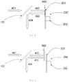
- the light engine comprises: a dichroic element 102; and a phosphor wheel 200'.
- the phosphor wheel 200' comprises a motor 202; a disc portion 203; and a polarisation converter 500.
- Source light 401 of a first colour is provided from a polarised source, such as a laser, which is typically polarised, for example as blue light with p polarization.
- a polarised source such as a laser
- p polarization we define the p polarization as linear polarization and the direction is in the plane of the paper. In contrast, s polarization is normal to the plane of the paper.
- dichroic element 102 The properties of the dichroic element 102 are dependent not only on the wavelength of the incident light, but also the polarisation of that light.
- dichroic element 102 is designed to pass light of p polarization blue light to cause excitation light 402 to be incident and focused on the disc portion 203 of the phosphor wheel 200'.
- the disc portion 203 of the phosphor wheel has a plurality of segments. Some of the plurality of segments contain one or more different kinds of phosphor. Excitation light 402, which is typically blue, is incident on these segments and converted to light of green, yellow, red or some other colour.
- the disc portion 203 is similar to the disc portion 201 shown in Figures 1A and 1B .
- the disc portion 203 of the phosphor wheel 200' has at least one other kind of segment.
- This segment does not include a phosphor. Rather, it comprises the polarization converter 500, which reflects p polarized light as s polarized light. In this way, the excitation light 402 is reflected together with emitted light 403, without a change in colour, but with a change in polarisation.
- the dichroic element 102 reflects the s polarized blue light as well as the converted light 403 emitted by the phosphor on the disc portion 203, to form the final output light 404.
- the dichroic element may reflect the green and red light emitted by the phosphor on the disc portion 203, irrespective of the polarisation of that light.
- polarisation converter 500 need not rotate.
- the polarization converter is shown as a quarter wave plate. However, other variants are possible.
- the polarisation converter 500 is attached to the phosphor wheel as one segment and rotates with the phosphor wheel.
- the polarisation converter 500 can be provided over the whole surface of the disc portion 203 of the phosphor wheel 200'.
- the polarisation converter 500 can be provided as a separate component to the phosphor wheel 200', as an insert between the dichroic element 102 and phosphor wheel 200'.
- the polarisation converter 500 can be provided at any place between the disc portion 203 and the dichroic element 102 as shown in Figure 3 .
- the polarisation converter 500 may be provided behind the phosphor wheel 200' as shown in Figure 4 .
- the disc portion 203 of the phosphor wheel 200' includes gap segments and, when light passes through these gap segments, it is reflected with a change in polarisation by the polarisation converter 500.
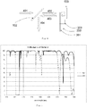
- FIG. 5 A graph illustrating a sample reflectance of a dichroic element is shown in Figure 5 . It will be seen that s polarisation light is reflected across most wavelengths. However, the dichroic element is designed that p polarisation light is not reflected when the colour is blue. This design is based on the principle that, if the incident light beam angle is not zero(in other words, not normalized incidence), the incident plane is defined such that the s and p polarization light will have different reflectance. Other reflectance profiles for the dichroic element are also possible, within the understanding of the skilled person.
- the light source advantageously comprises a part of the compact light engine, it will be understood that the invention can be implemented without the light source in place, but with a suitable optical input to receive the source light.
Landscapes
- Physics & Mathematics (AREA)
- General Physics & Mathematics (AREA)
- Engineering & Computer Science (AREA)
- Optics & Photonics (AREA)
- Spectroscopy & Molecular Physics (AREA)
- General Engineering & Computer Science (AREA)
- Multimedia (AREA)
- Astronomy & Astrophysics (AREA)
- Signal Processing (AREA)
- Projection Apparatus (AREA)
- Non-Portable Lighting Devices Or Systems Thereof (AREA)
Description
- The invention relates to a light engine comprising a light source, wavelength conversion device and a dichroic element, to a method of operating such a light engine and to a method of generating light.
- A common design of light sources for projectors uses a phosphor wheel to generate light of different colours sequentially. Typically, a blue laser excites the phosphor wheel to generate green or red colour light. The phosphor wheel normally has some fan segments which contain different types of phosphor to convert the exciting blue light to a green, yellow or red colour.
- The phosphor wheel can also have one or more gaps to pass the blue source light unconverted. A reflective type of phosphor wheel is often used, such that the excitation light and the emitted light stay on one side of the phosphor wheel. Then, a dichroic is used to separate the excitation light and emitted light.
- An example of a known such design is shown in
Figure 1A , comprising adichroic element 100 and aphosphor wheel 200. The phosphor wheel comprises adisc portion 201 and amotor 202 causing thedisc portion 201 to rotate. The sourceblue light 301 is passed by thedichroic element 100 and the passed blue light 302 (also referred to as the excitation light) is focused on thedisc 201 of thephosphor wheel 200. Thedisc portion 201 has at least one segment comprising a phosphor. Theblue excitation light 302 incident on such segments is absorbed by the phosphor and converted light 303 (typically green or red) is emitted. To extract the green orred light 303, thedichroic element 100 is used. Thedichroic element 100 reflects the emittedlight 303 and thereflected light 304 is output. The disc portion can have multiple segments with different phosphors, such that theoutput light 304 may be provided with different colours in sequence, as thedisc portion 201 is rotated. - The projector normally requires red, green and blue light to generate images. With
blue excitation light 302, the phosphor wheel would normally generate green andred output light 304. However, the design of this light engine demands that thedichroic element 100 passes blue light to reach thephosphor wheel 200. Thus, thedichroic element 100 cannot normally reflect any blue light received. - Some known technologies create blue light in a different way. The
disc portion 201 of thephosphor wheel 200 is designed with a gap segment. The gap segment allows thesource light 304 to pass through the phosphor wheel (not being reflected) and providessecondary output light 305 of the same colour as thesource light 301, for example blue light. - An alternative, known design of light engine is also shown in
Figure 1B . Similar light engine designs are discussed inUS-7,070,300 . This light engine achieves the same function as that shown inFigure 1A and mostly uses the same components. As a result, the same reference numerals have been used to identify the same features as shown inFigure 1A . However, the arrangement of the components is different inFigure 1B in comparison withFigure 1A . Moreover, thedichroic element 101 is different from thedichroic element 100 ofFigure 1A . - The
source light 301 is reflected by thedichroic element 101, causingexcitation light 302 to be incident on thedisc 202 of thephosphor wheel 200. The emittedlight 304, being of a different colour from theexcitation light 302, is then passed by thedichroic element 101. Again, the provision of light having the same colour as thesource light 301 is achieved by the use of a gap segment in thedisc portion 201 of thephosphor wheel 200. This allowssecondary output light 305 of the same colour as thesource light 301 to be provided. - Thus, for the designs shown in
Figures 1A and 1B , there are two output light paths. For example, one is provided for green and red light and a second for blue light. This results in additional components, increasing size, complexity and cost. -
US-2012/081674 describes a light source apparatus that includes: a light source; a reflection rotary body; an optical path changing element; and a polarization controller. - Against this background, the present invention provides a light engine. In a first aspect the light engine comprises: a wavelength conversion device, arranged to receive source light of a first wavelength range and a first polarisation, wherein the wavelength conversion device comprises a wheel, a first portion of the wheel surface being configured to generate light of a second wavelength range from a portion of the received source light, at least a portion of the second wavelength range being non-overlapping with the first wavelength range, the wavelength conversion device being further arranged to reflect output light comprising the generated light, wherein the wavelength conversion device further comprises a polarisation converter, either attached to or positioned behind the wheel configured to set at least some of the output light to a second polarisation, different from the first polarisation; and a dichroic element, arranged to receive the reflected output light, the dichroic element being configured to direct light of the first polarisation differently from light of the second polarisation.
- The dichroic mirror therefore separates light not only according to its colour, but also according to its polarisation. Consequently, output light of the same colour as the source light can be achieved simply by changing the polarisation of the excitation light reflected by a reflective segment of the phosphor wheel. This results in a much more compact light engine, with reduced complexity and cost.
- A number of preferable and optional features may be applicable.
- Preferably, the dichroic element is further arranged to direct the source light to be incident upon the wavelength conversion device. In the preferred embodiment, the wavelength conversion device is configured to reflect a portion of the received source light, the output light thereby comprising the generated light of the second wavelength range and reflected source light of the first wavelength range. Here, the polarisation converter is beneficially configured to set the reflected source light of the first wavelength range to the second polarisation. Optionally, the first polarisation and second polarisation are orthogonal.
- Advantageously, the dichroic element is configured to direct light of the first wavelength range and first polarisation differently from light of the first wavelength range and second polarisation.
- In the preferred embodiment, the dichroic element is configured to direct light of the first wavelength range and first polarisation differently from light of the second wavelength range. In some embodiments, the dichroic element may be configured to pass light of the first wavelength range and first polarisation and to reflect light of the first wavelength range and second polarisation and light of the second wavelength range. In other embodiments, the dichroic element is configured to reflect light of the first wavelength range and first polarisation and to pass light of the second wavelength range and light of the first wavelength range and second polarisation.
- In many embodiments, the second wavelength range is substantially non-overlapping with the first wavelength range. Then, the wavelength conversion device may comprise a phosphor element to generate light of the second wavelength range. The phosphor element may comprise any form of luminescent material.
- The wheel may be rotatable and, optionally, a motor may be provided to cause rotation of the wheel. The wheel may be formed of a disc-shaped portion as a substrate. The first portion of the wheel may comprise a phosphor coating on a segment of the surface of the substrate.
- Optionally, the wavelength conversion device is further configured to generate light of a third wavelength range from a portion of the received source light. When the wavelength conversion device is a wheel, a first portion of the wheel surface may be configured to generate light of the second wavelength range and a second portion of the wheel surface may be configured to generate light of the third wavelength range.
- In the preferred embodiment, a portion of the wheel surface is configured to reflect light of the first wavelength range. Prior art phosphor wheels requires an aperture in the disc portion of the wheel to allow excitation light to pass through the wheel. Typically, the transparent aperture is formed by removal of a portion of the phosphor wheel substrate. This causes a loss of balance of the wheel when it rotates. The improved disc-shaped substrate shape is employed, with an optional reflective coating on the substrate to reflect the light and cause it to pass though the polarisation converter. Advantageously, this may improve the balance of the wheel when rotated, facilitating its rotational ease. The phosphor wheel fabrication is also made more straightforward.
- In the preferred embodiment, the light engine further comprises a light source, arranged to provide the source light. The present invention is also embodied in a projector comprising the light engine as described herein.
- In a further aspect, the present invention may be found in a method of generating light, comprising: receiving source light of a first wavelength range and a first polarisation at a wavelength conversion device, wherein the wavelength conversion device comprises a wheel (200); generating light of a second wavelength range at a first portion of the wheel surface, from a portion of the received source light, at least a portion of the second wavelength range being non-overlapping with the first wavelength range, the wavelength conversion device therefore providing output light that comprises the generated light; setting the polarisation of at least some of the output light to a second polarisation, different from the first polarisation via use of a polarisation converter (500), either attached to or positioned behind the wheel (200'); and
reflecting the output light from the wavelength conversion device towards a dichroic element, the dichroic element being configured to direct light of the first polarisation differently from light of the second polarisation. - Again, a number of preferable and optional features may be applicable to any one or more of these method-based aspects. Moreover, it will be understood that method steps implementing the operation of any of the apparatus features described above can also be optionally provided.
- Preferably, the method further comprises: receiving the source light at the dichroic element; and directing the source light to be incident upon the wavelength conversion device using the dichroic element.
- Advantageously, the output light comprises the generated light of the second wavelength range and reflected source light of the first wavelength range, such that the step of reflecting the output light comprises reflecting a portion of the source light received at the wavelength conversion device towards the dichroic element. Optionally, the step of setting the polarisation comprises setting the reflected source light of the first wavelength range to the second polarisation. The dichroic element may be configured to direct light of the first wavelength range and first polarisation differently from light of the first wavelength range and second polarisation.
- Beneficially, the dichroic element is configured to affect light of the first wavelength range and first polarisation optically differently from light of the second wavelength range. Then, the method may further comprise: passing light of the first wavelength range and first polarisation received at the dichroic element; and reflecting light of the first wavelength range and second polarisation and light of the second wavelength range received at the dichroic element. Alternatively, the method may further comprise: reflecting light of the first wavelength range and first polarisation received at the dichroic element; and passing light of the first wavelength range and second polarisation and light of the second wavelength range received at the dichroic element.
- According to the invention, the second wavelength range is substantially non-overlapping with the first wavelength range. Then, generating light of a second wavelength range optionally comprises using a phosphor element.
- In some embodiments, the method may further comprise: generating light of a third wavelength range at the wavelength conversion device from a portion of the received source light, the third wavelength range being different from the first wavelength range and the second wavelength range. Where the wavelength conversion device is a wheel, a first portion of the wheel surface may be configured to generate light of the second wavelength range and a second portion of the wheel surface may be configured to generate light of the third wavelength range. Advantageously, a portion of the wheel surface is configured to reflect light of the first wavelength range.
- It will also be understood that the present invention is not limited to the specific combinations of features explicitly disclosed, but also includes any combination of features that are described independently and which the skilled person could implement together.
- The invention may be put into practice in various ways, a number of which will now be described by way of example only and with reference to the accompanying drawings in which:
-
Figure 1A shows a first embodiment of an existing light engine; -
Figure 1B shows a second embodiment of an existing light engine; -
Figure 2 shows a first embodiment of a light engine in accordance with the present invention; -
Figure 3 shows a second embodiment of a light engine not part of the present invention; -
Figure 4 shows a third embodiment of a light engine in accordance with the present invention; and -
Figure 5 shows a graph illustrating a sample reflectance of a dichroic element for use with any of the embodiments shown inFigures 2, 3 and4 . - Referring first to
Figure 2 , there is shown a first embodiment of a light engine in accordance with the present invention. The light engine comprises: adichroic element 102; and a phosphor wheel 200'. The phosphor wheel 200' comprises amotor 202; adisc portion 203; and apolarisation converter 500. -
Source light 401 of a first colour is provided from a polarised source, such as a laser, which is typically polarised, for example as blue light with p polarization. We define the p polarization as linear polarization and the direction is in the plane of the paper. In contrast, s polarization is normal to the plane of the paper. - The properties of the
dichroic element 102 are dependent not only on the wavelength of the incident light, but also the polarisation of that light. For instance,dichroic element 102 is designed to pass light of p polarization blue light to causeexcitation light 402 to be incident and focused on thedisc portion 203 of the phosphor wheel 200'. Thedisc portion 203 of the phosphor wheel has a plurality of segments. Some of the plurality of segments contain one or more different kinds of phosphor.Excitation light 402, which is typically blue, is incident on these segments and converted to light of green, yellow, red or some other colour. In this respect, thedisc portion 203 is similar to thedisc portion 201 shown inFigures 1A and 1B . - Beside these phosphor segments, the
disc portion 203 of the phosphor wheel 200' has at least one other kind of segment. This segment does not include a phosphor. Rather, it comprises thepolarization converter 500, which reflects p polarized light as s polarized light. In this way, theexcitation light 402 is reflected together with emitted light 403, without a change in colour, but with a change in polarisation. - The
dichroic element 102 reflects the s polarized blue light as well as the converted light 403 emitted by the phosphor on thedisc portion 203, to form thefinal output light 404. For instance, the dichroic element may reflect the green and red light emitted by the phosphor on thedisc portion 203, irrespective of the polarisation of that light. - Although embodiments of the invention have been described above, the skilled person may contemplate various modifications or substitutions.
- It will be understood that the
polarisation converter 500 need not rotate. The polarization converter is shown as a quarter wave plate. However, other variants are possible. - In the embodiment shown in
Figure 2 , thepolarisation converter 500 is attached to the phosphor wheel as one segment and rotates with the phosphor wheel. However, the skilled person will recognise that other embodiments are possible. For example, thepolarisation converter 500 can be provided over the whole surface of thedisc portion 203 of the phosphor wheel 200'. Alternatively, as an embodiment not part of the invention, thepolarisation converter 500 can be provided as a separate component to the phosphor wheel 200', as an insert between thedichroic element 102 and phosphor wheel 200'. Moreover, thepolarisation converter 500 can be provided at any place between thedisc portion 203 and thedichroic element 102 as shown inFigure 3 . - Indeed, the
polarisation converter 500 may be provided behind the phosphor wheel 200' as shown inFigure 4 . Similarly to the embodiment shown inFigure 1A , thedisc portion 203 of the phosphor wheel 200' includes gap segments and, when light passes through these gap segments, it is reflected with a change in polarisation by thepolarisation converter 500. - It will also be understood that embodiments based on those shown
Figures 2, 3 and4 , but with an arrangement of the type shown inFigure 1B will also be possible. In other words, these would be embodiments of the invention, based on those shownFigures 2, 3 and4 , but with a dichroic element designed to reflect source light of the source polarisation, but to pass light of a converted wavelength or light have the same colour as the source light, but with converted polarisation. - A graph illustrating a sample reflectance of a dichroic element is shown in
Figure 5 . It will be seen that s polarisation light is reflected across most wavelengths. However, the dichroic element is designed that p polarisation light is not reflected when the colour is blue. This design is based on the principle that, if the incident light beam angle is not zero(in other words, not normalized incidence), the incident plane is defined such that the s and p polarization light will have different reflectance. Other reflectance profiles for the dichroic element are also possible, within the understanding of the skilled person. - Although s polarisation and p polarisation of light have been used as examples, the skilled person will understand that other polarisations can be used. Similarly, other colour combinations can be used with different phosphors (or other kinds of wavelength conversion materials) being employed accordingly. The present invention may also be applicable to wavelength conversion devices other than phosphor wheels, for example colour wheels or other non-rotatable devices. Whilst the light source advantageously comprises a part of the compact light engine, it will be understood that the invention can be implemented without the light source in place, but with a suitable optical input to receive the source light.
Claims (18)
- A light engine, comprising:a wavelength conversion device, arranged to receive source light of a first wavelength range and a first polarisation, wherein the wavelength conversion device comprises a wheel (200'), a first portion of the wheel surface being configured to generate light of a second wavelength range from a portion of the received source light, at least a portion of the second wavelength range being non-overlapping with the first wavelength range, the wavelength conversion device being further arranged to reflect output light comprising the generated light, wherein the wavelength conversion device further comprises a polarisation converter (500), configured to set at least some of the output light to a second polarisation, different from the first polarisation; anda dichroic element (102), arranged to receive the reflected output light, the dichroic element (102) being configured to direct light of the first polarisation differently from light of the second polarisation, characterised in that said polarisation converter (500) is either attached to or positioned behind the wheel (200).
- The light engine of claim 1, wherein the dichroic element (102) is further arranged to direct the source light to be incident upon the wavelength conversion device.
- The light engine of claim 1 or claim 2, wherein the wavelength conversion device is configured to reflect a portion of the received source light, the output light thereby comprising the generated light of the second wavelength range and reflected source light of the first wavelength range.
- The light engine of claim 3, wherein the polarisation converter (500) is configured to set the reflected source light of the first wavelength range to the second polarisation.
- The light engine of claim 3 or claim 4, wherein the dichroic element (102) is configured to direct light of the first wavelength range and first polarisation differently from light of the first wavelength range and second polarisation.
- The light engine of any preceding claim, wherein the dichroic element (102) is configured to direct light of the first wavelength range and first polarisation differently from light of the second wavelength range.
- The light engine of claim 6, wherein the dichroic element(102) is configured to pass light of the first wavelength range and first polarisation and to reflect light of the first wavelength range and second polarisation and light of the second wavelength range.
- The light engine of claim 6, wherein the dichroic element (102) is configured to reflect light of the first wavelength range and first polarisation and to pass light of the second wavelength range and light of the first wavelength range and second polarisation.
- The light engine of any preceding claim, wherein the wavelength conversion device comprises a phosphor element to generate light of the second wavelength range.
- The light engine of any preceding claim, wherein the wavelength conversion device is further configured to generate light of a third wavelength range from a portion of the received source light.
- The light engine of claim 10, wherein the wavelength conversion device is a wheel (200'), a first portion of the wheel surface being configured to generate light of the second wavelength range and a second portion of the wheel surface being configured to generate light of the third wavelength range.
- The light engine of claim 10 or claim 11, wherein a portion of the wheel surface is configured to reflect light of the first wavelength range.
- The light engine of any preceding claim, further comprising:
a light source, arranged to provide the source light. - The light engine of any preceding claim, further comprising a motor (202) configured to cause the wheel (200') to rotate.
- The light engine of claim 14, wherein the polarisation converter (500) is attached to the wheel (200').
- The light engine of claim 15, wherein the polarisation converter (500) is disposed over the whole surface of the wheel (200').
- A projector comprising the light engine of any preceding claim.
- A method of generating light, comprising:receiving source light of a first wavelength range and a first polarisation at a wavelength conversion device, wherein the wavelength conversion device comprises a wheel (200) ;generating light of a second wavelength range at a first portion of the wheel surface, from a portion of the received source light, at least a portion of the second wavelength range being non-overlapping with the first wavelength range, the wavelength conversion device therefore providing output light that comprises the generated light;setting the polarisation of at least some of the output light to a second polarisation, different from the first polarisation via use of a polarisation converter (500), either attached to or positioned behind the wheel (200'); andreflecting the output light from the wavelength conversion device towards a dichroic element (102), the dichroic element (102) being configured to direct light of the first polarisation differently from light of the second polarisation.
Applications Claiming Priority (2)
| Application Number | Priority Date | Filing Date | Title |
|---|---|---|---|
| GBGB1213053.0A GB201213053D0 (en) | 2012-07-23 | 2012-07-23 | Compact light engine |
| PCT/GB2013/051952 WO2014016574A1 (en) | 2012-07-23 | 2013-07-22 | Compact light engine |
Publications (2)
| Publication Number | Publication Date |
|---|---|
| EP2875396A1 EP2875396A1 (en) | 2015-05-27 |
| EP2875396B1 true EP2875396B1 (en) | 2020-05-27 |
Family
ID=46881807
Family Applications (1)
| Application Number | Title | Priority Date | Filing Date |
|---|---|---|---|
| EP13742693.8A Active EP2875396B1 (en) | 2012-07-23 | 2013-07-22 | Compact light engine |
Country Status (8)
| Country | Link |
|---|---|
| US (1) | US9470398B2 (en) |
| EP (1) | EP2875396B1 (en) |
| JP (1) | JP6580486B2 (en) |
| KR (1) | KR20150036427A (en) |
| CN (2) | CN104508533A (en) |
| GB (1) | GB201213053D0 (en) |
| TW (1) | TWI597556B (en) |
| WO (1) | WO2014016574A1 (en) |
Families Citing this family (21)
| Publication number | Priority date | Publication date | Assignee | Title |
|---|---|---|---|---|
| US9235045B2 (en) * | 2013-01-16 | 2016-01-12 | Texas Instruments Incorporated | Phosphor wheel illumination using laser light reflective region |
| TWI522723B (en) | 2014-05-26 | 2016-02-21 | 台達電子工業股份有限公司 | Light source system and its suitable projection device |
| KR102216405B1 (en) | 2014-05-30 | 2021-02-16 | 엘지전자 주식회사 | Optical device and image projection apparatus including the same |
| CN105467732B (en) * | 2014-07-31 | 2018-12-04 | 欧司朗有限公司 | The light source module of optical projection apparatus and optical projection apparatus comprising light source module |
| WO2016161557A1 (en) | 2015-04-07 | 2016-10-13 | Materion Corporation | Optically enhanced solid-state light converters |
| CN106154717B (en) * | 2015-04-17 | 2018-04-13 | 深圳市光峰光电技术有限公司 | Light supply apparatus and there is its optical projection system |
| FR3036775B1 (en) * | 2015-05-29 | 2017-06-16 | Valeo Vision | SECURED LIGHTING MODULE WITH LASER LIGHT SOURCE |
| US10145541B2 (en) | 2015-06-12 | 2018-12-04 | Materion Corporation | Optical converter colour wheel |
| JP6575361B2 (en) * | 2016-01-07 | 2019-09-18 | セイコーエプソン株式会社 | Wavelength conversion element, lighting device and projector |
| KR102730458B1 (en) | 2016-03-02 | 2024-11-14 | 마테리온 코포레이션 | Optically enhanced light converter |
| CN108073022A (en) * | 2016-11-11 | 2018-05-25 | 鸿富锦精密工业(深圳)有限公司 | Projector light source device |
| CN106647126A (en) * | 2016-12-27 | 2017-05-10 | 苏州佳世达光电有限公司 | Light source apparatus and projection apparatus |
| CN108535944B (en) * | 2018-04-16 | 2021-04-13 | 成都九天光学技术有限公司 | Laser light source and control method thereof |
| JP7106349B2 (en) * | 2018-05-15 | 2022-07-26 | キヤノン株式会社 | Light source device and image projection device |
| CN111176058A (en) | 2018-11-09 | 2020-05-19 | 中强光电股份有限公司 | Polarization rotation device and projection device |
| KR102655480B1 (en) | 2019-01-22 | 2024-04-08 | 엘지전자 주식회사 | Projector |
| CN111983878B (en) | 2019-05-22 | 2021-10-29 | 中强光电股份有限公司 | Optical rotating device, lighting system and projection device |
| CN111221211A (en) * | 2020-03-19 | 2020-06-02 | 青岛海信激光显示股份有限公司 | Light source devices and laser projection equipment |
| EP4196719A1 (en) * | 2020-08-13 | 2023-06-21 | Signify Holding B.V. | Eye safe laser lighting system using built in safety |
| JP2021012375A (en) * | 2020-09-09 | 2021-02-04 | カシオ計算機株式会社 | Light source device and projection apparatus |
| WO2025257117A1 (en) | 2024-06-13 | 2025-12-18 | Signify Holding B.V. | New configuration for eye-safe laser lighting using depolarizing diffuser |
Family Cites Families (15)
| Publication number | Priority date | Publication date | Assignee | Title |
|---|---|---|---|---|
| US6176586B1 (en) | 1998-03-24 | 2001-01-23 | Minolta Co., Ltd. | Projection display apparatus |
| US7070300B2 (en) | 2004-06-04 | 2006-07-04 | Philips Lumileds Lighting Company, Llc | Remote wavelength conversion in an illumination device |
| US8267521B2 (en) | 2005-08-31 | 2012-09-18 | Sanyo Electric Co., Ltd. | Optical element, illuminating device, and projection type video display |
| US7547114B2 (en) * | 2007-07-30 | 2009-06-16 | Ylx Corp. | Multicolor illumination device using moving plate with wavelength conversion materials |
| JP5671666B2 (en) * | 2010-02-12 | 2015-02-18 | 日立マクセル株式会社 | Solid light source device and projection display device |
| JP5770433B2 (en) * | 2010-06-18 | 2015-08-26 | ソニー株式会社 | Light source device and image projection device |
| JP5474698B2 (en) * | 2010-07-29 | 2014-04-16 | 三洋電機株式会社 | Light source device and projection display device |
| JP5558996B2 (en) * | 2010-09-30 | 2014-07-23 | 三洋電機株式会社 | Light source device and projection display device |
| JP2012108486A (en) * | 2010-10-21 | 2012-06-07 | Panasonic Corp | Light source device and image display |
| JP5874058B2 (en) | 2010-12-06 | 2016-03-01 | パナソニックIpマネジメント株式会社 | Light source device and projection display device |
| JP5817109B2 (en) * | 2010-12-08 | 2015-11-18 | セイコーエプソン株式会社 | Light source device and projector |
| JP5743240B2 (en) * | 2011-03-18 | 2015-07-01 | Necディスプレイソリューションズ株式会社 | Illumination optical system provided with phosphor, projector, and irradiation method |
| US20120327374A1 (en) * | 2011-06-23 | 2012-12-27 | Panasonic Corporation | Illumination apparatus and projection display apparatus |
| JP5987368B2 (en) * | 2011-07-05 | 2016-09-07 | 株式会社リコー | Illumination device and projection device |
| JP5987382B2 (en) * | 2011-07-22 | 2016-09-07 | 株式会社リコー | LIGHTING DEVICE, PROJECTION DEVICE, AND METHOD FOR CONTROLLING PROJECTION DEVICE |
-
2012
- 2012-07-23 GB GBGB1213053.0A patent/GB201213053D0/en not_active Ceased
-
2013
- 2013-07-16 TW TW102125410A patent/TWI597556B/en active
- 2013-07-22 CN CN201380033382.1A patent/CN104508533A/en active Pending
- 2013-07-22 CN CN202011530076.7A patent/CN112526812B/en active Active
- 2013-07-22 JP JP2015523608A patent/JP6580486B2/en active Active
- 2013-07-22 WO PCT/GB2013/051952 patent/WO2014016574A1/en not_active Ceased
- 2013-07-22 US US14/415,763 patent/US9470398B2/en active Active
- 2013-07-22 EP EP13742693.8A patent/EP2875396B1/en active Active
- 2013-07-22 KR KR1020157003215A patent/KR20150036427A/en not_active Ceased
Non-Patent Citations (1)
| Title |
|---|
| None * |
Also Published As
| Publication number | Publication date |
|---|---|
| GB201213053D0 (en) | 2012-09-05 |
| WO2014016574A1 (en) | 2014-01-30 |
| TW201415155A (en) | 2014-04-16 |
| CN112526812B (en) | 2022-11-08 |
| CN112526812A (en) | 2021-03-19 |
| US9470398B2 (en) | 2016-10-18 |
| KR20150036427A (en) | 2015-04-07 |
| US20150204514A1 (en) | 2015-07-23 |
| JP6580486B2 (en) | 2019-09-25 |
| TWI597556B (en) | 2017-09-01 |
| EP2875396A1 (en) | 2015-05-27 |
| CN104508533A (en) | 2015-04-08 |
| JP2015529843A (en) | 2015-10-08 |
Similar Documents
| Publication | Publication Date | Title |
|---|---|---|
| US9470398B2 (en) | Compact light engine | |
| CN102289141B (en) | Illumination device and image display apparatus | |
| US9781394B2 (en) | Lighting device having phosphor wheel and excitation radiation source | |
| US9170423B2 (en) | Light module for a projection apparatus and method for generating the blue component in a light module for a projection apparatus | |
| US9664993B2 (en) | Light module for a projection device, DLP projector and method for producing a dichroic mirror | |
| KR20170056494A (en) | Light source device and image display apparatus | |
| CN110133951B (en) | Phosphor wheel, light source device and projection type image display device | |
| CN102346365A (en) | Projection type image display device | |
| JP6796751B2 (en) | Light source device and projection type image display device | |
| US20190369472A1 (en) | Combination wheel for light conversion | |
| US20170315431A1 (en) | Lighting device including pump radiation source | |
| CN110412819B (en) | Wavelength conversion element, phosphor wheel, light source device, and image display device | |
| CN106980220A (en) | Projection-type image display device | |
| US11388377B2 (en) | Display device and projection device | |
| US11199763B2 (en) | Projector | |
| CN109188709B (en) | Polarized light conversion device and light source system | |
| JP2018060127A (en) | Light source device | |
| EP3203732B1 (en) | Projection-type image display device | |
| US10620520B2 (en) | Wavelength conversion element, wavelength conversion system, light source apparatus, and projector | |
| JP2019139205A (en) | Phosphor wheel, light source device, and projection type video display device | |
| CN105222001B (en) | Light source module and color wheel manufacturing method | |
| WO2020179232A1 (en) | Optical element and projection-type display device | |
| EP3136721B1 (en) | System for producing an output light beam of a given spectrum | |
| JP2020003628A (en) | Phosphor wheel, light source device, and projection type video display device | |
| JP5786012B2 (en) | Projection display device |
Legal Events
| Date | Code | Title | Description |
|---|---|---|---|
| PUAI | Public reference made under article 153(3) epc to a published international application that has entered the european phase |
Free format text: ORIGINAL CODE: 0009012 |
|
| 17P | Request for examination filed |
Effective date: 20141218 |
|
| AK | Designated contracting states |
Kind code of ref document: A1 Designated state(s): AL AT BE BG CH CY CZ DE DK EE ES FI FR GB GR HR HU IE IS IT LI LT LU LV MC MK MT NL NO PL PT RO RS SE SI SK SM TR |
|
| AX | Request for extension of the european patent |
Extension state: BA ME |
|
| DAX | Request for extension of the european patent (deleted) | ||
| STAA | Information on the status of an ep patent application or granted ep patent |
Free format text: STATUS: EXAMINATION IS IN PROGRESS |
|
| 17Q | First examination report despatched |
Effective date: 20190703 |
|
| GRAP | Despatch of communication of intention to grant a patent |
Free format text: ORIGINAL CODE: EPIDOSNIGR1 |
|
| STAA | Information on the status of an ep patent application or granted ep patent |
Free format text: STATUS: GRANT OF PATENT IS INTENDED |
|
| INTG | Intention to grant announced |
Effective date: 20191212 |
|
| GRAS | Grant fee paid |
Free format text: ORIGINAL CODE: EPIDOSNIGR3 |
|
| GRAA | (expected) grant |
Free format text: ORIGINAL CODE: 0009210 |
|
| STAA | Information on the status of an ep patent application or granted ep patent |
Free format text: STATUS: THE PATENT HAS BEEN GRANTED |
|
| AK | Designated contracting states |
Kind code of ref document: B1 Designated state(s): AL AT BE BG CH CY CZ DE DK EE ES FI FR GB GR HR HU IE IS IT LI LT LU LV MC MK MT NL NO PL PT RO RS SE SI SK SM TR |
|
| REG | Reference to a national code |
Ref country code: GB Ref legal event code: FG4D |
|
| REG | Reference to a national code |
Ref country code: CH Ref legal event code: EP |
|
| REG | Reference to a national code |
Ref country code: AT Ref legal event code: REF Ref document number: 1275139 Country of ref document: AT Kind code of ref document: T Effective date: 20200615 |
|
| REG | Reference to a national code |
Ref country code: DE Ref legal event code: R096 Ref document number: 602013069402 Country of ref document: DE |
|
| REG | Reference to a national code |
Ref country code: NL Ref legal event code: FP |
|
| REG | Reference to a national code |
Ref country code: NO Ref legal event code: T2 Effective date: 20200527 |
|
| REG | Reference to a national code |
Ref country code: LT Ref legal event code: MG4D |
|
| PG25 | Lapsed in a contracting state [announced via postgrant information from national office to epo] |
Ref country code: LT Free format text: LAPSE BECAUSE OF FAILURE TO SUBMIT A TRANSLATION OF THE DESCRIPTION OR TO PAY THE FEE WITHIN THE PRESCRIBED TIME-LIMIT Effective date: 20200527 Ref country code: SE Free format text: LAPSE BECAUSE OF FAILURE TO SUBMIT A TRANSLATION OF THE DESCRIPTION OR TO PAY THE FEE WITHIN THE PRESCRIBED TIME-LIMIT Effective date: 20200527 Ref country code: IS Free format text: LAPSE BECAUSE OF FAILURE TO SUBMIT A TRANSLATION OF THE DESCRIPTION OR TO PAY THE FEE WITHIN THE PRESCRIBED TIME-LIMIT Effective date: 20200927 Ref country code: GR Free format text: LAPSE BECAUSE OF FAILURE TO SUBMIT A TRANSLATION OF THE DESCRIPTION OR TO PAY THE FEE WITHIN THE PRESCRIBED TIME-LIMIT Effective date: 20200828 Ref country code: FI Free format text: LAPSE BECAUSE OF FAILURE TO SUBMIT A TRANSLATION OF THE DESCRIPTION OR TO PAY THE FEE WITHIN THE PRESCRIBED TIME-LIMIT Effective date: 20200527 Ref country code: PT Free format text: LAPSE BECAUSE OF FAILURE TO SUBMIT A TRANSLATION OF THE DESCRIPTION OR TO PAY THE FEE WITHIN THE PRESCRIBED TIME-LIMIT Effective date: 20200928 |
|
| PG25 | Lapsed in a contracting state [announced via postgrant information from national office to epo] |
Ref country code: RS Free format text: LAPSE BECAUSE OF FAILURE TO SUBMIT A TRANSLATION OF THE DESCRIPTION OR TO PAY THE FEE WITHIN THE PRESCRIBED TIME-LIMIT Effective date: 20200527 Ref country code: HR Free format text: LAPSE BECAUSE OF FAILURE TO SUBMIT A TRANSLATION OF THE DESCRIPTION OR TO PAY THE FEE WITHIN THE PRESCRIBED TIME-LIMIT Effective date: 20200527 Ref country code: LV Free format text: LAPSE BECAUSE OF FAILURE TO SUBMIT A TRANSLATION OF THE DESCRIPTION OR TO PAY THE FEE WITHIN THE PRESCRIBED TIME-LIMIT Effective date: 20200527 Ref country code: BG Free format text: LAPSE BECAUSE OF FAILURE TO SUBMIT A TRANSLATION OF THE DESCRIPTION OR TO PAY THE FEE WITHIN THE PRESCRIBED TIME-LIMIT Effective date: 20200827 |
|
| REG | Reference to a national code |
Ref country code: AT Ref legal event code: MK05 Ref document number: 1275139 Country of ref document: AT Kind code of ref document: T Effective date: 20200527 |
|
| PG25 | Lapsed in a contracting state [announced via postgrant information from national office to epo] |
Ref country code: AL Free format text: LAPSE BECAUSE OF FAILURE TO SUBMIT A TRANSLATION OF THE DESCRIPTION OR TO PAY THE FEE WITHIN THE PRESCRIBED TIME-LIMIT Effective date: 20200527 |
|
| PG25 | Lapsed in a contracting state [announced via postgrant information from national office to epo] |
Ref country code: CZ Free format text: LAPSE BECAUSE OF FAILURE TO SUBMIT A TRANSLATION OF THE DESCRIPTION OR TO PAY THE FEE WITHIN THE PRESCRIBED TIME-LIMIT Effective date: 20200527 Ref country code: RO Free format text: LAPSE BECAUSE OF FAILURE TO SUBMIT A TRANSLATION OF THE DESCRIPTION OR TO PAY THE FEE WITHIN THE PRESCRIBED TIME-LIMIT Effective date: 20200527 Ref country code: ES Free format text: LAPSE BECAUSE OF FAILURE TO SUBMIT A TRANSLATION OF THE DESCRIPTION OR TO PAY THE FEE WITHIN THE PRESCRIBED TIME-LIMIT Effective date: 20200527 Ref country code: IT Free format text: LAPSE BECAUSE OF FAILURE TO SUBMIT A TRANSLATION OF THE DESCRIPTION OR TO PAY THE FEE WITHIN THE PRESCRIBED TIME-LIMIT Effective date: 20200527 Ref country code: AT Free format text: LAPSE BECAUSE OF FAILURE TO SUBMIT A TRANSLATION OF THE DESCRIPTION OR TO PAY THE FEE WITHIN THE PRESCRIBED TIME-LIMIT Effective date: 20200527 Ref country code: EE Free format text: LAPSE BECAUSE OF FAILURE TO SUBMIT A TRANSLATION OF THE DESCRIPTION OR TO PAY THE FEE WITHIN THE PRESCRIBED TIME-LIMIT Effective date: 20200527 Ref country code: SM Free format text: LAPSE BECAUSE OF FAILURE TO SUBMIT A TRANSLATION OF THE DESCRIPTION OR TO PAY THE FEE WITHIN THE PRESCRIBED TIME-LIMIT Effective date: 20200527 Ref country code: DK Free format text: LAPSE BECAUSE OF FAILURE TO SUBMIT A TRANSLATION OF THE DESCRIPTION OR TO PAY THE FEE WITHIN THE PRESCRIBED TIME-LIMIT Effective date: 20200527 |
|
| PG25 | Lapsed in a contracting state [announced via postgrant information from national office to epo] |
Ref country code: SK Free format text: LAPSE BECAUSE OF FAILURE TO SUBMIT A TRANSLATION OF THE DESCRIPTION OR TO PAY THE FEE WITHIN THE PRESCRIBED TIME-LIMIT Effective date: 20200527 Ref country code: PL Free format text: LAPSE BECAUSE OF FAILURE TO SUBMIT A TRANSLATION OF THE DESCRIPTION OR TO PAY THE FEE WITHIN THE PRESCRIBED TIME-LIMIT Effective date: 20200527 Ref country code: MC Free format text: LAPSE BECAUSE OF FAILURE TO SUBMIT A TRANSLATION OF THE DESCRIPTION OR TO PAY THE FEE WITHIN THE PRESCRIBED TIME-LIMIT Effective date: 20200527 |
|
| REG | Reference to a national code |
Ref country code: CH Ref legal event code: PL |
|
| REG | Reference to a national code |
Ref country code: DE Ref legal event code: R097 Ref document number: 602013069402 Country of ref document: DE |
|
| PLBE | No opposition filed within time limit |
Free format text: ORIGINAL CODE: 0009261 |
|
| STAA | Information on the status of an ep patent application or granted ep patent |
Free format text: STATUS: NO OPPOSITION FILED WITHIN TIME LIMIT |
|
| GBPC | Gb: european patent ceased through non-payment of renewal fee |
Effective date: 20200827 |
|
| PG25 | Lapsed in a contracting state [announced via postgrant information from national office to epo] |
Ref country code: CH Free format text: LAPSE BECAUSE OF NON-PAYMENT OF DUE FEES Effective date: 20200731 Ref country code: LI Free format text: LAPSE BECAUSE OF NON-PAYMENT OF DUE FEES Effective date: 20200731 Ref country code: FR Free format text: LAPSE BECAUSE OF NON-PAYMENT OF DUE FEES Effective date: 20200727 Ref country code: LU Free format text: LAPSE BECAUSE OF NON-PAYMENT OF DUE FEES Effective date: 20200722 |
|
| 26N | No opposition filed |
Effective date: 20210302 |
|
| PG25 | Lapsed in a contracting state [announced via postgrant information from national office to epo] |
Ref country code: SI Free format text: LAPSE BECAUSE OF FAILURE TO SUBMIT A TRANSLATION OF THE DESCRIPTION OR TO PAY THE FEE WITHIN THE PRESCRIBED TIME-LIMIT Effective date: 20200527 |
|
| PG25 | Lapsed in a contracting state [announced via postgrant information from national office to epo] |
Ref country code: GB Free format text: LAPSE BECAUSE OF NON-PAYMENT OF DUE FEES Effective date: 20200827 Ref country code: IE Free format text: LAPSE BECAUSE OF NON-PAYMENT OF DUE FEES Effective date: 20200722 |
|
| PG25 | Lapsed in a contracting state [announced via postgrant information from national office to epo] |
Ref country code: TR Free format text: LAPSE BECAUSE OF FAILURE TO SUBMIT A TRANSLATION OF THE DESCRIPTION OR TO PAY THE FEE WITHIN THE PRESCRIBED TIME-LIMIT Effective date: 20200527 Ref country code: MT Free format text: LAPSE BECAUSE OF FAILURE TO SUBMIT A TRANSLATION OF THE DESCRIPTION OR TO PAY THE FEE WITHIN THE PRESCRIBED TIME-LIMIT Effective date: 20200527 Ref country code: CY Free format text: LAPSE BECAUSE OF FAILURE TO SUBMIT A TRANSLATION OF THE DESCRIPTION OR TO PAY THE FEE WITHIN THE PRESCRIBED TIME-LIMIT Effective date: 20200527 |
|
| PG25 | Lapsed in a contracting state [announced via postgrant information from national office to epo] |
Ref country code: MK Free format text: LAPSE BECAUSE OF FAILURE TO SUBMIT A TRANSLATION OF THE DESCRIPTION OR TO PAY THE FEE WITHIN THE PRESCRIBED TIME-LIMIT Effective date: 20200527 |
|
| P01 | Opt-out of the competence of the unified patent court (upc) registered |
Effective date: 20230526 |
|
| PGFP | Annual fee paid to national office [announced via postgrant information from national office to epo] |
Ref country code: NL Payment date: 20240716 Year of fee payment: 12 |
|
| PGFP | Annual fee paid to national office [announced via postgrant information from national office to epo] |
Ref country code: DE Payment date: 20240722 Year of fee payment: 12 |
|
| PGFP | Annual fee paid to national office [announced via postgrant information from national office to epo] |
Ref country code: BE Payment date: 20240716 Year of fee payment: 12 |
|
| PGFP | Annual fee paid to national office [announced via postgrant information from national office to epo] |
Ref country code: NO Payment date: 20240719 Year of fee payment: 12 |
|
| REG | Reference to a national code |
Ref country code: DE Ref legal event code: R119 Ref document number: 602013069402 Country of ref document: DE |
|
| REG | Reference to a national code |
Ref country code: NL Ref legal event code: MM Effective date: 20250801 |
|
| REG | Reference to a national code |
Ref country code: BE Ref legal event code: MM Effective date: 20250731 |
|
| PG25 | Lapsed in a contracting state [announced via postgrant information from national office to epo] |
Ref country code: NO Free format text: LAPSE BECAUSE OF NON-PAYMENT OF DUE FEES Effective date: 20250731 Ref country code: DE Free format text: LAPSE BECAUSE OF NON-PAYMENT OF DUE FEES Effective date: 20260203 |
|
| PG25 | Lapsed in a contracting state [announced via postgrant information from national office to epo] |
Ref country code: BE Free format text: LAPSE BECAUSE OF NON-PAYMENT OF DUE FEES Effective date: 20250731 |
|
| PG25 | Lapsed in a contracting state [announced via postgrant information from national office to epo] |
Ref country code: NL Free format text: LAPSE BECAUSE OF NON-PAYMENT OF DUE FEES Effective date: 20250801 |