EP2874416A1 - Telecommunications network responsive to server-provided location information - Google Patents
Telecommunications network responsive to server-provided location information Download PDFInfo
- Publication number
- EP2874416A1 EP2874416A1 EP20140192408 EP14192408A EP2874416A1 EP 2874416 A1 EP2874416 A1 EP 2874416A1 EP 20140192408 EP20140192408 EP 20140192408 EP 14192408 A EP14192408 A EP 14192408A EP 2874416 A1 EP2874416 A1 EP 2874416A1
- Authority
- EP
- European Patent Office
- Prior art keywords
- terminal
- network
- network node
- location
- server
- Prior art date
- Legal status (The legal status is an assumption and is not a legal conclusion. Google has not performed a legal analysis and makes no representation as to the accuracy of the status listed.)
- Granted
Links
Images

Classifications
-
- H—ELECTRICITY
- H04—ELECTRIC COMMUNICATION TECHNIQUE
- H04W—WIRELESS COMMUNICATION NETWORKS
- H04W4/00—Services specially adapted for wireless communication networks; Facilities therefor
- H04W4/70—Services for machine-to-machine communication [M2M] or machine type communication [MTC]
-
- H—ELECTRICITY
- H04—ELECTRIC COMMUNICATION TECHNIQUE
- H04W—WIRELESS COMMUNICATION NETWORKS
- H04W4/00—Services specially adapted for wireless communication networks; Facilities therefor
- H04W4/02—Services making use of location information
-
- H—ELECTRICITY
- H04—ELECTRIC COMMUNICATION TECHNIQUE
- H04W—WIRELESS COMMUNICATION NETWORKS
- H04W4/00—Services specially adapted for wireless communication networks; Facilities therefor
- H04W4/02—Services making use of location information
- H04W4/029—Location-based management or tracking services
-
- H—ELECTRICITY
- H04—ELECTRIC COMMUNICATION TECHNIQUE
- H04W—WIRELESS COMMUNICATION NETWORKS
- H04W48/00—Access restriction; Network selection; Access point selection
- H04W48/17—Selecting a data network PoA [Point of Attachment]
-
- H—ELECTRICITY
- H04—ELECTRIC COMMUNICATION TECHNIQUE
- H04W—WIRELESS COMMUNICATION NETWORKS
- H04W76/00—Connection management
- H04W76/10—Connection setup
- H04W76/14—Direct-mode setup
-
- H—ELECTRICITY
- H04—ELECTRIC COMMUNICATION TECHNIQUE
- H04W—WIRELESS COMMUNICATION NETWORKS
- H04W76/00—Connection management
- H04W76/10—Connection setup
-
- H—ELECTRICITY
- H04—ELECTRIC COMMUNICATION TECHNIQUE
- H04W—WIRELESS COMMUNICATION NETWORKS
- H04W8/00—Network data management
- H04W8/02—Processing of mobility data, e.g. registration information at HLR [Home Location Register] or VLR [Visitor Location Register]; Transfer of mobility data, e.g. between HLR, VLR or external networks
- H04W8/08—Mobility data transfer
Definitions
- the invention is in the field of telecommunications and, particularly, in the field of machine-to-machine communications employing telecommunications networks.
- the location identifier may indeed comprise geographical information, cell information where the terminal is located in the RAN and/or location area or routing area information.
- An address of the second network node may not be known at the server, and should in such a case be derived at the first network node from the location identifier.
- claims 6 and 11 cover the situation wherein the terminals provide the further location information to the second network node.
- the address of the second service node is obtained using the location identifier received from the server, whereas the more detailed information is available at or retrievable by the second network node.
- (Indications of) locations may include the SGSN via which the terminal 3 can be connected, cell identifiers of the RAN/UTRAN, Location Areas, Routing Areas, geographical coordinates, and/or postal address.
- the further location information may already have been included in the location identifier of the data unit received at the GGSN and been forwarded to the SGSN. It should be appreciated that the relevant SGSN may be derived from the location identifier as received by the GGSN.
- the further location information may also have been pre-stored at the GGSN and been transferred to the SGSN at the receipt of a data unit at the GGSN.
- the SGSN may directly initiate paging, i.e. a connection request, for the terminal 3 in the part of the RAN identified by the further location information.
- the further location information may be received from the terminal 3 itself.
- the further location information is than stored at or retrievable by the SGSN upon receipt of a connection request from the GGSN. Again, when the SGSN is triggered in this manner, the SGSN may initiate paging, i.e. a connection request, for the terminal 3 in the part of the RAN identified by the further location information.
Landscapes
- Engineering & Computer Science (AREA)
- Computer Networks & Wireless Communication (AREA)
- Signal Processing (AREA)
- Computer Security & Cryptography (AREA)
- Mobile Radio Communication Systems (AREA)
Abstract
Description
- The invention is in the field of telecommunications and, particularly, in the field of machine-to-machine communications employing telecommunications networks.
- The past decades have shown an ever increasing demand for data capacity of telecommunications networks. Telecommunications providers have adapted their networks to provide extended services to meet the demands of their clients.
- One example of such services relates to the field of machine-to-machine (M2M) communications. M2M applications typi-cally involve hundreds or thousands of communication modules that only rarely require access to a telecommunications network. An example involves the electronic reading of e.g. electricity meters at the homes of a large customer base from a server. Other examples include sensors, meters, coffee machines etc that can be equipped with communication modules that allow for reporting status information to a data processing centre over the telecommunications network. Such devices may also be monitored from a server. The data processing centre may e.g. store the data and/or provide a schedule for maintenance people to repair a machine, meter, sensor etc.
- The contemporary networks (GPRS and UMTS) and proposals for future networks (Evolved Packet System (EPS)) used for wireless telephony and data services are organized relatively inefficiently for M2M applications. Such applications involve large amounts of terminals, but these terminals are typically characterized by a low mobility, i.e. the terminals are typically stationed at one location or within one cell for a significant period of time.
- To that end, a telecommunications network is disclosed that is configured for wirelessly establishing a connection with a terminal located at a location in said network by a server. The terminal is identified by a terminal identifier in the telecommunications network. The telecommunications network contains a first network node and a second network node.
- The first network node is configured for receiving a data unit for the terminal from the server, that may be located in or outside the telecommunications network. The data unit comprises the terminal identifier. The first network node is being configured for receiving a location identifier indicative of the location of the terminal from the server and for deriving an address of the second network node using the location identifier. The derived address of the second network node is then used for transmitting a first connection request to the second network node for establishing a connection to the terminal.
- The second network node is configured for receiving the first connection request from the first network node and for transmitting a second connection request for establishing the connection towards the terminal.
- Furthermore, a method for wirelessly establishing a network-initiated connection with a terminal located at a location in a telecommunications network by a server is disclosed. The terminal is identified by a terminal identifier in the telecommunications network. A data unit for the terminal is received from the server at a first network node, wherein the data unit comprises the terminal identifier. Also, a location identifier is received at the first network node from the server that is indicative of the location of the terminal in the telecommunications network. In the first network node, an address of a second network node is derived using the location identifier. A connection request is then transmitted from the first network node to the thus derived second network node.
- Still further, a computer program, a first network node, a second network node and a server are disclosed for use in or with the telecommunications network and/or the method in such a network.
- Conventionally, the mobility of mobile terminals requires the use of mobility management procedures and the connection to such terminals requires location updates in and location requests to network nodes of the telecommunications network, typically referred to as a Home Location Register (HLR) and a Visitor Location Register (VLR) as generally known to a skilled person.
- Since the mobility of the terminals in the M2M communications system is relatively low, the location of the terminals is generally known at a server that is typically used for transmitting or receiving data to and from the terminals, respectively. This fact is advantageously used by feeding a location identifier of the terminal to a network node that receives a data unit for this terminal. This location identifier obviates the need for requesting a location of a terminal and/or the address of another service node from a HLR, thereby reducing signal flow and reducing location storage and updates in the telecommunications network.
- Furthermore, the terminal (or the SIM card thereof, if any) cannot be reached outside the area indicated by the location identifier, thereby making theft of the often unattended terminal or SIM card less attractive.
- It should be noted that the location identifier may indeed comprise geographical information, cell information where the terminal is located in the RAN and/or location area or routing area information. An address of the second network node may not be known at the server, and should in such a case be derived at the first network node from the location identifier.
- The location identifier can be received from the server in the data unit as defined in
claims 2 and 8, thereby obviating the need for a location identifier interface between the server and the first network node. - The location identifier may be pre-stored at the first network node as defined in
claim 3, i.e. the location identifier is stored at the first network node before a first data unit is received from the server. The location identifier may e.g. have been obtained at the first network node during a previous connection and been stored. The location identifier, however, may also be obtained in the first network node from the server separately from the data unit, as defined inclaims 4 and 9. Such an embodiment provides the advantage of an unmodified data unit and allows for changing location parameters of the terminal independently from the transmission of data units to the terminal. - The embodiments of
claims 5 and 10 are advantageous in that further location information is contained in, represented by or derivable from the location identifier. The further location information may comprise a Location Area (LA), a routing area (RA) and/or a cell identifier. The further location information is decisive for the part (e.g. one or more cells) of the telecommunications network wherein the connection request is transmitted upon initiation by the second network node. As the further location information is received at the second network node, there is no need for the second network node to obtain this further location information from elsewhere. - The embodiments of claims 6 and 11 cover the situation wherein the terminals provide the further location information to the second network node. In these embodiments, the address of the second service node is obtained using the location identifier received from the server, whereas the more detailed information is available at or retrievable by the second network node.
- Hereinafter, embodiments of the invention will be described in further detail. It should be appreciated, however, that these embodiments may not be construed as limiting the scope of protection for the present invention.
- In the drawings:
-
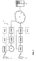
FIG. 1 is a schematic illustration of a telecommunications network according to an embodiment of the invention; -
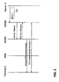
FIGS. 2 and3 are time diagram schematically illustration an operating example of the telecommunications network ofFIG. 1 -
FIG. 1 shows a schematic illustration of a telecommunications network 1 according to an embodiment of the invention. The telecommunications network 1 allows communication between aserver 2 and aterminal 3 over apacket data network 4, wherein access or the terminal to the telecommunications network 1 is wireless. - In the telecommunications network of
FIG. 1 , three generations of telecommunications networks are depicted together for purposes of brevity. - The lower branch represents a GPRS or UMTS telecommunications network comprising a GPRS Gateway Support Node (GGSN), a Serving GPRS Support Node (SGSN) and a Radio Access Network (RAN or UTRAN). For a GSM/EDGE radio access network (GERAN), the RAN comprises a Base Station Controller (BSC) connected to a plurality of Base Station Transceivers (BTSs), both not shown. For a UMTS radio access network (UTRAN), the RAN comprises a Radio Network Controller (RNC) connected to a plurality of NodeB's), also not shown. The GGSN is conventionally connected to a Home Location Register (HLR).
- Further information of the general architecture of a mobile network can be found in 3GPP TS 23.002 and for the GPRS core network in 3GPP TS 23.060.
- The upper branch in
FIG. 1 represents a next generation telecommunications network, commonly indicated as Long Term Evolution (LTE) or Evolved Packet System (EPS). Such a network comprises a Gateway GW containing a P-GW and a S-GW for an operator. The e-UTRAN of EPS comprises enhanced NodeB's (eNodeB's) providing wireless access for aterminal 3 that are connected to the GW via apacket network 5. The S-GW is connected to a Home Subscriber Server HSS and a Mobility Management Entity MME for signalling purposes. - Further information of the general architecture of a EPS network can be found in 3GPP TS 23.401.
- Of course, architectures other than defined by 3GGP can also be used within the context of the present invention.
- Whereas the invention as defined in the appended claims is generally applicable to such networks, a more detailed description will be provided below for a GPRS/UMTS network.
- For such a network, the SGSN typically controls the connection between the telecommunications network 1 and the
terminal 3. It should be appreciated that the telecommunications network 1 generally comprises a plurality of SGSNs, wherein each of the SGSNs is connected typically to several BSC's/RNC's to provide a packet service forterminals 3 via several base stations/NodeB's. Each SGSN normally comprises a Visitor Location Register (VLR), not shown inFIG. 1 . - The GGSN is connected to the
packet data network 4, e.g. the internet, a corporate network or a network of another operator. On the other side, the GGSN is connected to a plurality of SGSN's. - The GGSN is configured for receiving a data unit for the terminal 3 from the
server 2 over thenetwork 4. The data unit contains a terminal identifier, such as an IP address, of theterminal 3. The GGSN normally contains the IMSI of theterminal 3 and selects the IMSI of theterminal 3 on the basis of the IP address received from theserver 2. - Conventionally,
terminal 3 is non-stationary, and the network 1 has to find out the present location of theterminal 3. Finding the present location of theterminal 3 generally involves a plurality of steps, as known to the person skilled in the art, including a request to the HLR for the presently responsible SGSN for the Location Area or Routing Area in the RAN/UTRAN where theterminal 3 is presently located, and paging. Such procedures are described in 3GPP TS 23.060 and 3GPP 29.060. The paging for establishing the connection is described in e.g. 3GPP 25.413. - The present disclosure is based on the insight that for M2M applications, the location of a
terminal 3 may still not be known in the telecommunications network 1 but will generally be known to theserver 2 for the organisation operating theserver 2 will generally deploy theterminals 3 in the field or at least have instructed where in the telecommunications network 1 theterminals 3 should be deployed. - This insight can be used to advantage by informing the telecommunications network 1 of (an indication of) the location of the terminal(s) 3 from the
server 2, such that a network-initiated connection to theterminal 3 may be performed without requiring access to a HLR. This saves considerable resources in the network, including storage capacity in the HLR (no need to store or update terminal locations) as well as bandwidth (no need for requests to and responses from the HLR). - (Indications of) locations may include the SGSN via which the
terminal 3 can be connected, cell identifiers of the RAN/UTRAN, Location Areas, Routing Areas, geographical coordinates, and/or postal address. - Various alternatives have been envisaged for informing the telecommunications network 1, particularly the GGSN thereof, of the (indication of the) location of a terminal 3 from the
server 2. - In a first alternative, a location identifier indicative of the location of the
terminal 3 in the telecommunications network 1 is contained in the (first) data unit that is received by the GGSN. - In a second alternative, the location identifier may be pre-stored in the GGSN before a first data unit is received from the
server 2. The location identifier may e.g. have been obtained at the GGSN during a previous connection and been stored after terminating the connection. - The location identifier, however, may also be obtained by the GGSN from the
server 2 separately from the data unit. This alternative provides the advantage of an unmodified data unit and allows for changing location parameters of theterminal 3 independently from the transmission of data units to theterminal 3. - As mentioned above, the location identifier as provided by the
server 2 may contain an identifier of the SGSN via which a connection to theterminal 3 can be established. Of course, in order to eventually contact theterminal 3, further location information of theterminal 3 in thetelecommunications network 3, particularly the RAN/UTRAN thereof, is required. Such further information may comprise one or more cell identifiers of cells of the RAN/UTRAN wherein theterminal 3 is located, a location area or a routing area. - Various alternatives have been envisaged to obtain the further location information in the telecommunications network, particularly the SGSN thereof.
- Firstly, the further location information may already have been included in the location identifier of the data unit received at the GGSN and been forwarded to the SGSN. It should be appreciated that the relevant SGSN may be derived from the location identifier as received by the GGSN. The further location information may also have been pre-stored at the GGSN and been transferred to the SGSN at the receipt of a data unit at the GGSN. When the SGSN receives the further location information, the SGSN may directly initiate paging, i.e. a connection request, for the
terminal 3 in the part of the RAN identified by the further location information. - Secondly, the further location information may be received from the
terminal 3 itself. The further location information is than stored at or retrievable by the SGSN upon receipt of a connection request from the GGSN. Again, when the SGSN is triggered in this manner, the SGSN may initiate paging, i.e. a connection request, for theterminal 3 in the part of the RAN identified by the further location information. - It should be noted that data may either be transferred via the SGSN or by-passing the SGSN and be transferred directly to the RNC. Signalling always involves the SGSN for GPRS networks. The RNC may replace the function of the SGSN in the above paragraphs in case data bypasses the SGSN.
- In case of an EPS network, the function of the GGSN is performed by the GW, and the eNodeB or another S-GW (in case another operator is involved, e.g. when roaming) constitutes a second network node.
- It should be appreciated that, while the present disclosure relates to packet-switched communications, the invention equally applies to circuit-switched communications. This requires a modification of the procedure described in 3GPP TS 23.018 along the lines described below for packet-switched communications.
-
FIGS. 2 and3 are time diagrams for a GPRS telecommunications network 1 schematically illustrating an example of signal flow between the various components of the telecommunications network 1, theserver 2 and theterminal 3.FIG. 2 illustrates a network-requested POP context activation procedure, which is initiated when a data packet DF arrives at the GGSN. The data packet includes a terminal identifier, e.g. an IP address, and a location identifier, LI. The GGSN has information, the IMSI, which relates to a particular IP address. - Conventionally, the IMSI is used to for requesting routing information from the HLR. The HLR returns the address of the SGSN via which the terminal can be connected.
- As the data packet DP from the
server 2 includes a location identifier, this step can be omitted. - When receiving the data packet DP, the GGSN determines if the network-requested PDP context activation procedure has to be initiated. The GGSN stores subsequent data packets received for the same address.
- The GGSN derives the address of the relevant SGSN from the location identifier in the data packet DP and sends a PDU notification request message to the thus derived GGSN, the request containing the IMSI, PDP type, PDP Address and APN. The request may also contain a further information element containing further location information, e.g. a cell identifier, a routing area, a location area etc, that can be used by the SGSN for initiating the paging procedure described below with reference to
FIG. 3 . - The SGSN returns a PDU notification response message to the GGSN in order to acknowledge that it shall request the
terminal 3 to activate the PDP context indicated with the PDP Address. - In a next step, the SGSN sends a request PDP context activation message via the RAN to the
terminal 3 and the PDP context is activated. - Now the PDP context has been activated, the data packet DP can be transferred to the SGSN.
- The next steps perform a network initiated service request procedure from the SGSN to the
terminal 3. Various alternatives exist, but generally, the SGSN initiates a paging message in the identified part of the RAN. As described above, the further information for transmitting this paging message from a part of the RAN may be obtained at the SGSN in various ways. -
FIG. 3 is a timing diagram illustrating a network initiated service request procedure for a GPRS telecommunications network 1. - In a first step, the data packet DP, contained in a further packet, is received at the SGSN.
- The SGSN sends a paging message to the RNC of the RAN. The RNC pages the
terminal 3 by sending a paging message to theterminal 3 that requests an RRC connection to the RNC. The RRC connection is set up and a service request is subsequently transmitted from theterminal 3 to the SGSN. The SGSN may then perform security procedures, if necessary. - Finally, a radio bearer is established and a SGSN-Initiated PDP context modification procedure is performed to deliver the data packet DP at the
terminal 3.
Claims (4)
- A first network node configured for use in a telecommunications network for wirelessly establishing a connection with a terminal located at a location in said network by a server, the terminal being identified by a terminal identifier in the telecommunications network, wherein the telecommunications network contains the first network node and a second network node, and wherein
the first network node is configured for receiving a data unit for the terminal from the server, the data unit comprising the terminal identifier,
the first network node is configured for receiving a location identifier indicative of the location of the terminal in the telecommunications network and for deriving an address of the second network node using the location identifier and transmitting a first connection request to the derived second network node for establishing a connection to the terminal, characterized in that
the first network node is configured for receiving the location identifier from the server. - The first network node according to claim 1, wherein the data unit comprises the location identifier.
- The first network node according to claim 1, wherein the first network node is configured for storing the location identifier and for retrieving the location identifier in response to receiving the data unit from the server.
- The first network node according to claim 3, wherein the first network node comprises a signalling interface for the server, and wherein the signalling interface is configured for receiving the location identifier of the terminal separately from the data unit.
Priority Applications (2)
| Application Number | Priority Date | Filing Date | Title |
|---|---|---|---|
| ES14192408.4T ES2584844T3 (en) | 2009-04-28 | 2009-04-28 | Telecommunications network that responds to location information provided by a server |
| EP14192408.4A EP2874416B1 (en) | 2009-04-28 | 2009-04-28 | Telecommunications network responsive to server-provided location information |
Applications Claiming Priority (2)
| Application Number | Priority Date | Filing Date | Title |
|---|---|---|---|
| EP14192408.4A EP2874416B1 (en) | 2009-04-28 | 2009-04-28 | Telecommunications network responsive to server-provided location information |
| EP20090005866 EP2247144B1 (en) | 2009-04-28 | 2009-04-28 | Telecommunications network responsive to server-provided location information |
Related Parent Applications (3)
| Application Number | Title | Priority Date | Filing Date |
|---|---|---|---|
| EP20090005866 Division EP2247144B1 (en) | 2009-04-28 | 2009-04-28 | Telecommunications network responsive to server-provided location information |
| EP20090005866 Previously-Filed-Application EP2247144B1 (en) | 2009-04-28 | 2009-04-28 | Telecommunications network responsive to server-provided location information |
| EP20090005866 Division-Into EP2247144B1 (en) | 2009-04-28 | 2009-04-28 | Telecommunications network responsive to server-provided location information |
Publications (2)
| Publication Number | Publication Date |
|---|---|
| EP2874416A1 true EP2874416A1 (en) | 2015-05-20 |
| EP2874416B1 EP2874416B1 (en) | 2016-04-27 |
Family
ID=41254619
Family Applications (2)
| Application Number | Title | Priority Date | Filing Date |
|---|---|---|---|
| EP14192408.4A Active EP2874416B1 (en) | 2009-04-28 | 2009-04-28 | Telecommunications network responsive to server-provided location information |
| EP20090005866 Active EP2247144B1 (en) | 2009-04-28 | 2009-04-28 | Telecommunications network responsive to server-provided location information |
Family Applications After (1)
| Application Number | Title | Priority Date | Filing Date |
|---|---|---|---|
| EP20090005866 Active EP2247144B1 (en) | 2009-04-28 | 2009-04-28 | Telecommunications network responsive to server-provided location information |
Country Status (4)
| Country | Link |
|---|---|
| US (3) | US8588137B2 (en) |
| EP (2) | EP2874416B1 (en) |
| ES (2) | ES2532956T3 (en) |
| PL (1) | PL2247144T3 (en) |
Families Citing this family (6)
| Publication number | Priority date | Publication date | Assignee | Title |
|---|---|---|---|---|
| CN102196402B (en) * | 2010-03-08 | 2016-06-15 | 中兴通讯股份有限公司 | The method and system of terminals in wireless communication systems switching |
| WO2011149252A2 (en) * | 2010-05-26 | 2011-12-01 | Lg Electronics Inc. | Nas-based signaling protocol for overload protection of random access in massive machine type communication |
| WO2011163561A1 (en) | 2010-06-25 | 2011-12-29 | Interdigital Patend Holdings, Inc. | Interface of an m2m server with the 3gpp core network |
| EP2632213B1 (en) * | 2010-10-21 | 2016-12-21 | LG Electronics Inc. | Method and apparatus for performing network entry/reentry in wireless communication system |
| CN102142980B (en) | 2010-10-27 | 2014-05-07 | 华为技术有限公司 | Method and gateway for remotely managing sensor network topology |
| CN107484211B (en) * | 2016-06-08 | 2020-06-26 | 华为技术有限公司 | Method and device for switching access point |
Citations (4)
| Publication number | Priority date | Publication date | Assignee | Title |
|---|---|---|---|---|
| US20030204627A1 (en) * | 2002-04-30 | 2003-10-30 | Jerry Mizell | PDP context distribution among multiple GGSNs |
| WO2005122617A1 (en) * | 2004-06-08 | 2005-12-22 | Telefonaktiebolaget Lm Ericsson (Publ) | Apparatuses and method to provide a network-requested pdp context activation procedure |
| US7027800B2 (en) * | 1998-06-29 | 2006-04-11 | Nokia Corporation | Method and system of providing a service to a subscriber |
| WO2008127155A1 (en) * | 2007-04-13 | 2008-10-23 | Telefonaktiebolaget Lm Ericsson (Publ) | Communication of information between devices in communication networks |
Family Cites Families (5)
| Publication number | Priority date | Publication date | Assignee | Title |
|---|---|---|---|---|
| FI109164B (en) * | 2000-05-15 | 2002-05-31 | Sonera Oyj | Activation of packet data protocol context upon request from the network |
| JP4186480B2 (en) * | 2002-03-05 | 2008-11-26 | 日本電気株式会社 | Mobile portable terminal and always-on PDP context management method used therefor |
| EP1487220A4 (en) * | 2002-03-15 | 2008-03-05 | Fujitsu Ltd | SYSTEM AND METHOD FOR PROVIDING POSITION INFORMATION |
| US20070135121A1 (en) * | 2005-12-08 | 2007-06-14 | Electronics And Telecommunications Research Institute | User and service mobility support system and method in ubiquitous environment |
| US8504032B2 (en) | 2008-06-12 | 2013-08-06 | At&T Intellectual Property I, L.P. | Femtocell service registration, activation, and provisioning |
-
2009
- 2009-04-28 EP EP14192408.4A patent/EP2874416B1/en active Active
- 2009-04-28 EP EP20090005866 patent/EP2247144B1/en active Active
- 2009-04-28 PL PL09005866T patent/PL2247144T3/en unknown
- 2009-04-28 ES ES09005866.0T patent/ES2532956T3/en active Active
- 2009-04-28 ES ES14192408.4T patent/ES2584844T3/en active Active
-
2010
- 2010-04-28 US US12/769,018 patent/US8588137B2/en active Active
-
2013
- 2013-10-17 US US14/055,998 patent/US9137625B2/en active Active
-
2015
- 2015-08-19 US US14/830,030 patent/US20150359025A1/en not_active Abandoned
Patent Citations (4)
| Publication number | Priority date | Publication date | Assignee | Title |
|---|---|---|---|---|
| US7027800B2 (en) * | 1998-06-29 | 2006-04-11 | Nokia Corporation | Method and system of providing a service to a subscriber |
| US20030204627A1 (en) * | 2002-04-30 | 2003-10-30 | Jerry Mizell | PDP context distribution among multiple GGSNs |
| WO2005122617A1 (en) * | 2004-06-08 | 2005-12-22 | Telefonaktiebolaget Lm Ericsson (Publ) | Apparatuses and method to provide a network-requested pdp context activation procedure |
| WO2008127155A1 (en) * | 2007-04-13 | 2008-10-23 | Telefonaktiebolaget Lm Ericsson (Publ) | Communication of information between devices in communication networks |
Also Published As
| Publication number | Publication date |
|---|---|
| US20150359025A1 (en) | 2015-12-10 |
| US9137625B2 (en) | 2015-09-15 |
| EP2247144A1 (en) | 2010-11-03 |
| US20140044049A1 (en) | 2014-02-13 |
| EP2874416B1 (en) | 2016-04-27 |
| ES2532956T3 (en) | 2015-04-06 |
| EP2247144B1 (en) | 2015-01-07 |
| US20100272020A1 (en) | 2010-10-28 |
| PL2247144T3 (en) | 2015-06-30 |
| ES2584844T3 (en) | 2016-09-29 |
| US8588137B2 (en) | 2013-11-19 |
Similar Documents
| Publication | Publication Date | Title |
|---|---|---|
| CN115102588B (en) | Paging policy differentiation in 5G systems | |
| US10681767B2 (en) | Method and apparatus for performing RRC connection resume in wireless communication system | |
| US9271222B2 (en) | Method and apparatus for implementing access to machine to machine (M2M) core network | |
| EP2763496B1 (en) | Communication system, method and apparatus | |
| EP2761928B1 (en) | Methods and apparatuses for device triggering | |
| EP3402299B1 (en) | User device and data transmission method therefor, and network node and data transmission method therefor | |
| EP2869610B1 (en) | Method and device for updating area in wireless communication system | |
| CN101610494B (en) | Method, system and device for realizing overload control or differentiated service | |
| US20150359025A1 (en) | Telecommunications Network Responsive to Server-Provided Location Information | |
| US9730056B2 (en) | System, method, and apparatus for facilitating selection of a serving node | |
| EP3393168B1 (en) | User equipment and data reception method, and network node and data transmission method | |
| EP2811767A1 (en) | Control method for the connection between user equipment and network and mobile management equipment | |
| EP2245882A1 (en) | Auto configuration of mobility entity | |
| EP3435699B1 (en) | Method for transmitting message and user equipment | |
| US20150029978A1 (en) | Avoiding unlimited number of unsuccessful location update or packet data connection establishment attempts | |
| US20120113895A1 (en) | System and method for providing information indicating the priority level of a non access stratum signaling message and for using the priority level information to select a response | |
| US9537817B2 (en) | Method and apparatus for obtaining destination IP address | |
| KR20230085654A (en) | Method for monitoring and improving network slice quality in a mobile communication network and apparatus therefor | |
| EP2699041A1 (en) | Equipment triggering method and network elememnt equipment | |
| WO2016174512A1 (en) | Resource control for wireless device detach | |
| CN103227983A (en) | Method, system and equipment realizing overload control or differential service |
Legal Events
| Date | Code | Title | Description |
|---|---|---|---|
| PUAI | Public reference made under article 153(3) epc to a published international application that has entered the european phase |
Free format text: ORIGINAL CODE: 0009012 |
|
| 17P | Request for examination filed |
Effective date: 20141110 |
|
| AC | Divisional application: reference to earlier application |
Ref document number: 2247144 Country of ref document: EP Kind code of ref document: P |
|
| AK | Designated contracting states |
Kind code of ref document: A1 Designated state(s): AT BE BG CH CY CZ DE DK EE ES FI FR GB GR HR HU IE IS IT LI LT LU LV MC MK MT NL NO PL PT RO SE SI SK TR |
|
| R17P | Request for examination filed (corrected) |
Effective date: 20151120 |
|
| RBV | Designated contracting states (corrected) |
Designated state(s): AT BE BG CH CY CZ DE DK EE ES FI FR GB GR HR HU IE IS IT LI LT LU LV MC MK MT NL NO PL PT RO SE SI SK TR |
|
| GRAP | Despatch of communication of intention to grant a patent |
Free format text: ORIGINAL CODE: EPIDOSNIGR1 |
|
| INTG | Intention to grant announced |
Effective date: 20160129 |
|
| GRAS | Grant fee paid |
Free format text: ORIGINAL CODE: EPIDOSNIGR3 |
|
| GRAA | (expected) grant |
Free format text: ORIGINAL CODE: 0009210 |
|
| AC | Divisional application: reference to earlier application |
Ref document number: 2247144 Country of ref document: EP Kind code of ref document: P |
|
| AK | Designated contracting states |
Kind code of ref document: B1 Designated state(s): AT BE BG CH CY CZ DE DK EE ES FI FR GB GR HR HU IE IS IT LI LT LU LV MC MK MT NL NO PL PT RO SE SI SK TR |
|
| REG | Reference to a national code |
Ref country code: GB Ref legal event code: FG4D |
|
| REG | Reference to a national code |
Ref country code: CH Ref legal event code: EP |
|
| REG | Reference to a national code |
Ref country code: AT Ref legal event code: REF Ref document number: 795935 Country of ref document: AT Kind code of ref document: T Effective date: 20160515 |
|
| REG | Reference to a national code |
Ref country code: IE Ref legal event code: FG4D |
|
| REG | Reference to a national code |
Ref country code: DE Ref legal event code: R096 Ref document number: 602009038310 Country of ref document: DE |
|
| REG | Reference to a national code |
Ref country code: FR Ref legal event code: PLFP Year of fee payment: 8 |
|
| REG | Reference to a national code |
Ref country code: NL Ref legal event code: FP |
|
| REG | Reference to a national code |
Ref country code: SE Ref legal event code: TRGR |
|
| REG | Reference to a national code |
Ref country code: LT Ref legal event code: MG4D |
|
| PG25 | Lapsed in a contracting state [announced via postgrant information from national office to epo] |
Ref country code: BE Free format text: LAPSE BECAUSE OF NON-PAYMENT OF DUE FEES Effective date: 20160430 |
|
| REG | Reference to a national code |
Ref country code: AT Ref legal event code: MK05 Ref document number: 795935 Country of ref document: AT Kind code of ref document: T Effective date: 20160427 |
|
| REG | Reference to a national code |
Ref country code: ES Ref legal event code: FG2A Ref document number: 2584844 Country of ref document: ES Kind code of ref document: T3 Effective date: 20160929 |
|
| PG25 | Lapsed in a contracting state [announced via postgrant information from national office to epo] |
Ref country code: LT Free format text: LAPSE BECAUSE OF FAILURE TO SUBMIT A TRANSLATION OF THE DESCRIPTION OR TO PAY THE FEE WITHIN THE PRESCRIBED TIME-LIMIT Effective date: 20160427 Ref country code: FI Free format text: LAPSE BECAUSE OF FAILURE TO SUBMIT A TRANSLATION OF THE DESCRIPTION OR TO PAY THE FEE WITHIN THE PRESCRIBED TIME-LIMIT Effective date: 20160427 Ref country code: NO Free format text: LAPSE BECAUSE OF FAILURE TO SUBMIT A TRANSLATION OF THE DESCRIPTION OR TO PAY THE FEE WITHIN THE PRESCRIBED TIME-LIMIT Effective date: 20160727 Ref country code: PL Free format text: LAPSE BECAUSE OF FAILURE TO SUBMIT A TRANSLATION OF THE DESCRIPTION OR TO PAY THE FEE WITHIN THE PRESCRIBED TIME-LIMIT Effective date: 20160427 |
|
| PG25 | Lapsed in a contracting state [announced via postgrant information from national office to epo] |
Ref country code: AT Free format text: LAPSE BECAUSE OF FAILURE TO SUBMIT A TRANSLATION OF THE DESCRIPTION OR TO PAY THE FEE WITHIN THE PRESCRIBED TIME-LIMIT Effective date: 20160427 Ref country code: GR Free format text: LAPSE BECAUSE OF FAILURE TO SUBMIT A TRANSLATION OF THE DESCRIPTION OR TO PAY THE FEE WITHIN THE PRESCRIBED TIME-LIMIT Effective date: 20160728 Ref country code: PT Free format text: LAPSE BECAUSE OF FAILURE TO SUBMIT A TRANSLATION OF THE DESCRIPTION OR TO PAY THE FEE WITHIN THE PRESCRIBED TIME-LIMIT Effective date: 20160829 Ref country code: LV Free format text: LAPSE BECAUSE OF FAILURE TO SUBMIT A TRANSLATION OF THE DESCRIPTION OR TO PAY THE FEE WITHIN THE PRESCRIBED TIME-LIMIT Effective date: 20160427 Ref country code: HR Free format text: LAPSE BECAUSE OF FAILURE TO SUBMIT A TRANSLATION OF THE DESCRIPTION OR TO PAY THE FEE WITHIN THE PRESCRIBED TIME-LIMIT Effective date: 20160427 |
|
| REG | Reference to a national code |
Ref country code: CH Ref legal event code: PL |
|
| PG25 | Lapsed in a contracting state [announced via postgrant information from national office to epo] |
Ref country code: BE Free format text: LAPSE BECAUSE OF FAILURE TO SUBMIT A TRANSLATION OF THE DESCRIPTION OR TO PAY THE FEE WITHIN THE PRESCRIBED TIME-LIMIT Effective date: 20160427 Ref country code: IT Free format text: LAPSE BECAUSE OF FAILURE TO SUBMIT A TRANSLATION OF THE DESCRIPTION OR TO PAY THE FEE WITHIN THE PRESCRIBED TIME-LIMIT Effective date: 20160427 |
|
| REG | Reference to a national code |
Ref country code: IE Ref legal event code: MM4A |
|
| REG | Reference to a national code |
Ref country code: DE Ref legal event code: R097 Ref document number: 602009038310 Country of ref document: DE |
|
| PG25 | Lapsed in a contracting state [announced via postgrant information from national office to epo] |
Ref country code: CZ Free format text: LAPSE BECAUSE OF FAILURE TO SUBMIT A TRANSLATION OF THE DESCRIPTION OR TO PAY THE FEE WITHIN THE PRESCRIBED TIME-LIMIT Effective date: 20160427 Ref country code: CH Free format text: LAPSE BECAUSE OF NON-PAYMENT OF DUE FEES Effective date: 20160430 Ref country code: RO Free format text: LAPSE BECAUSE OF FAILURE TO SUBMIT A TRANSLATION OF THE DESCRIPTION OR TO PAY THE FEE WITHIN THE PRESCRIBED TIME-LIMIT Effective date: 20160427 Ref country code: DK Free format text: LAPSE BECAUSE OF FAILURE TO SUBMIT A TRANSLATION OF THE DESCRIPTION OR TO PAY THE FEE WITHIN THE PRESCRIBED TIME-LIMIT Effective date: 20160427 Ref country code: SK Free format text: LAPSE BECAUSE OF FAILURE TO SUBMIT A TRANSLATION OF THE DESCRIPTION OR TO PAY THE FEE WITHIN THE PRESCRIBED TIME-LIMIT Effective date: 20160427 Ref country code: EE Free format text: LAPSE BECAUSE OF FAILURE TO SUBMIT A TRANSLATION OF THE DESCRIPTION OR TO PAY THE FEE WITHIN THE PRESCRIBED TIME-LIMIT Effective date: 20160427 Ref country code: LI Free format text: LAPSE BECAUSE OF NON-PAYMENT OF DUE FEES Effective date: 20160430 Ref country code: MC Free format text: LAPSE BECAUSE OF FAILURE TO SUBMIT A TRANSLATION OF THE DESCRIPTION OR TO PAY THE FEE WITHIN THE PRESCRIBED TIME-LIMIT Effective date: 20160427 |
|
| PLBE | No opposition filed within time limit |
Free format text: ORIGINAL CODE: 0009261 |
|
| STAA | Information on the status of an ep patent application or granted ep patent |
Free format text: STATUS: NO OPPOSITION FILED WITHIN TIME LIMIT |
|
| 26N | No opposition filed |
Effective date: 20170130 |
|
| REG | Reference to a national code |
Ref country code: FR Ref legal event code: PLFP Year of fee payment: 9 |
|
| PG25 | Lapsed in a contracting state [announced via postgrant information from national office to epo] |
Ref country code: SI Free format text: LAPSE BECAUSE OF FAILURE TO SUBMIT A TRANSLATION OF THE DESCRIPTION OR TO PAY THE FEE WITHIN THE PRESCRIBED TIME-LIMIT Effective date: 20160427 Ref country code: IE Free format text: LAPSE BECAUSE OF NON-PAYMENT OF DUE FEES Effective date: 20160428 |
|
| REG | Reference to a national code |
Ref country code: FR Ref legal event code: PLFP Year of fee payment: 10 |
|
| PG25 | Lapsed in a contracting state [announced via postgrant information from national office to epo] |
Ref country code: HU Free format text: LAPSE BECAUSE OF FAILURE TO SUBMIT A TRANSLATION OF THE DESCRIPTION OR TO PAY THE FEE WITHIN THE PRESCRIBED TIME-LIMIT; INVALID AB INITIO Effective date: 20090428 |
|
| PG25 | Lapsed in a contracting state [announced via postgrant information from national office to epo] |
Ref country code: MT Free format text: LAPSE BECAUSE OF NON-PAYMENT OF DUE FEES Effective date: 20160430 Ref country code: IS Free format text: LAPSE BECAUSE OF FAILURE TO SUBMIT A TRANSLATION OF THE DESCRIPTION OR TO PAY THE FEE WITHIN THE PRESCRIBED TIME-LIMIT Effective date: 20160427 Ref country code: LU Free format text: LAPSE BECAUSE OF NON-PAYMENT OF DUE FEES Effective date: 20160428 Ref country code: CY Free format text: LAPSE BECAUSE OF FAILURE TO SUBMIT A TRANSLATION OF THE DESCRIPTION OR TO PAY THE FEE WITHIN THE PRESCRIBED TIME-LIMIT Effective date: 20160427 Ref country code: MK Free format text: LAPSE BECAUSE OF FAILURE TO SUBMIT A TRANSLATION OF THE DESCRIPTION OR TO PAY THE FEE WITHIN THE PRESCRIBED TIME-LIMIT Effective date: 20160427 |
|
| PG25 | Lapsed in a contracting state [announced via postgrant information from national office to epo] |
Ref country code: BG Free format text: LAPSE BECAUSE OF FAILURE TO SUBMIT A TRANSLATION OF THE DESCRIPTION OR TO PAY THE FEE WITHIN THE PRESCRIBED TIME-LIMIT Effective date: 20160427 |
|
| PG25 | Lapsed in a contracting state [announced via postgrant information from national office to epo] |
Ref country code: TR Free format text: LAPSE BECAUSE OF FAILURE TO SUBMIT A TRANSLATION OF THE DESCRIPTION OR TO PAY THE FEE WITHIN THE PRESCRIBED TIME-LIMIT Effective date: 20160427 |
|
| P01 | Opt-out of the competence of the unified patent court (upc) registered |
Effective date: 20230517 |
|
| PGFP | Annual fee paid to national office [announced via postgrant information from national office to epo] |
Ref country code: NL Payment date: 20260420 Year of fee payment: 18 |
|
| PGFP | Annual fee paid to national office [announced via postgrant information from national office to epo] |
Ref country code: ES Payment date: 20260529 Year of fee payment: 18 |
|
| PGFP | Annual fee paid to national office [announced via postgrant information from national office to epo] |
Ref country code: GB Payment date: 20260423 Year of fee payment: 18 |
|
| PGFP | Annual fee paid to national office [announced via postgrant information from national office to epo] |
Ref country code: DE Payment date: 20260422 Year of fee payment: 18 |
|
| PGFP | Annual fee paid to national office [announced via postgrant information from national office to epo] |
Ref country code: SE Payment date: 20260420 Year of fee payment: 18 |
|
| PGFP | Annual fee paid to national office [announced via postgrant information from national office to epo] |
Ref country code: FR Payment date: 20260420 Year of fee payment: 18 |