EP2874408A1 - Loudspeaker polarity detector - Google Patents
Loudspeaker polarity detector Download PDFInfo
- Publication number
- EP2874408A1 EP2874408A1 EP20130192918 EP13192918A EP2874408A1 EP 2874408 A1 EP2874408 A1 EP 2874408A1 EP 20130192918 EP20130192918 EP 20130192918 EP 13192918 A EP13192918 A EP 13192918A EP 2874408 A1 EP2874408 A1 EP 2874408A1
- Authority
- EP
- European Patent Office
- Prior art keywords
- loudspeaker
- impedance
- signal
- polarity
- impedance values
- Prior art date
- Legal status (The legal status is an assumption and is not a legal conclusion. Google has not performed a legal analysis and makes no representation as to the accuracy of the status listed.)
- Granted
Links
Images


Classifications
-
- H—ELECTRICITY
- H04—ELECTRIC COMMUNICATION TECHNIQUE
- H04R—LOUDSPEAKERS, MICROPHONES, GRAMOPHONE PICK-UPS OR LIKE ACOUSTIC ELECTROMECHANICAL TRANSDUCERS; ELECTRIC HEARING AIDS; PUBLIC ADDRESS SYSTEMS
- H04R29/00—Monitoring arrangements; Testing arrangements
- H04R29/001—Monitoring arrangements; Testing arrangements for loudspeakers
-
- H—ELECTRICITY
- H04—ELECTRIC COMMUNICATION TECHNIQUE
- H04R—LOUDSPEAKERS, MICROPHONES, GRAMOPHONE PICK-UPS OR LIKE ACOUSTIC ELECTROMECHANICAL TRANSDUCERS; ELECTRIC HEARING AIDS; PUBLIC ADDRESS SYSTEMS
- H04R5/00—Stereophonic arrangements
- H04R5/04—Circuit arrangements, e.g. for selective connection of amplifier inputs/outputs to loudspeakers, for loudspeaker detection, or for adaptation of settings to personal preferences or hearing impairments
-
- G—PHYSICS
- G01—MEASURING; TESTING
- G01R—MEASURING ELECTRIC VARIABLES; MEASURING MAGNETIC VARIABLES
- G01R19/00—Arrangements for measuring currents or voltages or for indicating presence or sign thereof
- G01R19/14—Indicating direction of current; Indicating polarity of voltage
Definitions
- This invention relates to loudspeakers, and particularly, but not exclusively to detecting the polarity of a loudspeaker.
- Loudspeakers generally comprise a diaphragm (or cone), connected to a rigid frame, via a flexible suspension that constrains a voice coil to move axially through a cylindrical magnetic gap.
- a voice coil When an electrical signal is applied to the voice coil, a magnetic field is created by the electric current in the voice coil, making it a variable electromagnet.
- the coil and the driver's magnetic system interact, generating a mechanical force that causes the coil (and thus, the attached diaphragm) to move back and forth, thereby reproducing sound under the control of the applied electrical signal coming from the amplifier.
- the polarity of a loudspeaker determines whether the loudspeaker diaphragm (e.g. cone) moves out or in relative to the voltage polarity of the signal.
- loudspeakers In audio systems with multiple loudspeakers, it may be important to connect the loudspeakers in phase with each other (i.e., with the same polarity). If they are connected incorrectly, the audio signal will not be reproduced faithfully. For example, if two loudspeakers with different polarity receive the same signal, at any given instant one loudspeaker diaphragm (e.g. cone) will be moving out and the other moving in. This may cause phase cancellations at certain frequencies and may be very noticeable. That is, the stereo image may be distorted or the low frequencies may be attenuated (because the low frequencies of one loudspeaker may cancel those of another). Therefore, ensuring that loudspeakers are connected with the correct polarity may mitigate the effects of the loudspeaker diaphragm of different loudspeakers moving in counterphase (or anti-phase).
- the polarity of the loudspeakers may affect the audio output signal, it may be possible to measure the polarity using, for example, a microphone. However, this may require additional equipment and may be affected by other acoustic effects (e.g. by the shape of the room).
- the method may comprise the step of determining a plurality of impedance values of a loudspeaker, each of the impedance values corresponding to a different input signal or input signal portions provided to the loudspeaker.
- the signal portions may comprise different temporal segments of a signal.
- the step of determining the polarity of the loudspeaker may comprise calculating the difference between a first impedance corresponding to a first input signal and a second impedance corresponding to a second input signal, wherein
- the method may comprise the step of determining a plurality of impedance values for different portions of an input signal, the input signal comprising:
- the step of determining the polarity of the loudspeaker may comprise comparing the determined one or more impedance values with corresponding reference values.
- the corresponding reference values may comprise at least one of:
- the comparison may comprise temporal cross-correlation of the determined one or more impedance values and the corresponding reference values.
- the step of determining the one or more impedance values may comprise determining a plurality of impedance values for a number of different input signals, each input signal being distinguished by at least one of: having a different frequency; and comprising a different DC-value.
- the step of determining the polarity of the loudspeaker may comprise comparing the plurality of impedance values with corresponding impedance values measured for a different loudspeaker.
- the step of determining each impedance value may comprise measuring:
- the method may comprise the step of determining the relative polarity of the loudspeaker with respect to other loudspeakers in a loudspeaker system.
- an apparatus comprising:
- the apparatus may determine the impedance and/or polarity using one of the described methods.
- the polarity determining module may comprise a processor.
- the impedance determining module may comprise:
- the apparatus may, or may not, comprise a signal generator configured to generate a predetermined signal, and wherein the apparatus is configured to determine a plurality of impedance values of a loudspeaker, each of the impedance values corresponding to a different input signal or input signal portion provided to the loudspeaker.
- the apparatus may or may not comprise the loudspeaker.
- a computer program comprising computer program code configured to:
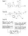
- a loudspeaker system 100 is illustrated in figure 1 which comprises two loudspeakers 101, 102.
- the loudspeaker system comprises a dualchannel amplifier 103 with two loudspeakers 101, 102 connected to it: one loudspeaker 101 with normal polarity; the other loudspeaker 102 with reverse polarity.
- a positive voltage results in an outward movement of the loudspeaker diaphragm
- a negative voltage results in an inward movement of the diaphragm
- the electrical impedance of a loudspeaker changes as a function of the diaphragm displacement. This is because the impedance of the loudspeaker is affected by changes in other loudspeaker parameters (such as the BI-factor, the inductance and the stiffness) which in turn are affected by the diaphragm displacement. Therefore, movement of the diaphragm effects the electrical impedance of the loudspeaker.
- This invention relates to a method and system to determine the polarity of a single or multiple loudspeakers by analysing the electrical impedance variations of the loudspeaker(s) and/or variations in the diaphragm displacement (or related signals).
- Figure 2a depicts a first embodiment 200 of the invention, comprising an apparatus configured to determine the polarity of a loudspeaker.
- the apparatus comprises: a signal generator 211; an amplifier 222; a loudspeaker 201; an impedance determining module 202; and a polarity determining module, which in this case is a processor 203.
- a voltage sensing means such as a voltage sense amplifier
- a current sensing means such as a current sense amplifier
- a calibration method (shown in figure 2b ) is used to determine the absolute polarity of the loudspeaker 201 by determining whether the loudspeaker impedance is increased or decreased as a function of a positive DC voltage.
- the inductance of a loudspeaker that is connected with normal polarity is expected to decrease for an outward movement of the loudspeaker, and so, because the impedance of the loudspeaker is related to its inductance, the absolute polarity of a loudspeaker can be determined using measurements of the impedance.
- the impedance of a loudspeaker consists of, among others, a resistance, a motor impedance (resonance peak) and an inductance.
- the relative components making up the impedance vary with frequency. For example, the impedance is predominantly determined by the inductance at higher frequencies.
- the effect of the loudspeaker impedance variation is measured at frequencies where the motor impedance is small, e.g., two octaves higher than the resonance frequency of the loudspeaker. In that frequency region, the effect of the variation of many other loudspeaker parameters (e.g., those constituting the motor impedance) is expected to be very small, and the loudspeaker impedance is predominantly determined by its inductance (which varies with diaphragm displacement). It will be appreciated that other embodiments may use other frequencies.
- the calibration method comprises providing a first test signal to the loudspeaker 201 comprising a signal with a predetermined frequency.
- the first test signal may, for example, comprise a small amplitude sine wave at the predetermined frequency, ⁇ o (say, two octaves above the resonance frequency of the loudspeaker). Other non-sinusoidal waveforms may also be used provided that there is a non-zero signal component at the predetermined frequency.
- the signal is provided using the signal generator 211 and amplified using the amplifier 222.
- the magnitude of the first electrical impedance is determined (e.g.
- the method further comprises applying a second test signal, which consists of the first test signal (i.e. also comprising a signal with a predetermined frequency ⁇ o ) with a positive DC voltage signal added to it.
- a second test signal which consists of the first test signal (i.e. also comprising a signal with a predetermined frequency ⁇ o ) with a positive DC voltage signal added to it.
- provision and measurement corresponding to the second test signal may be carried out before or after the provision and measurement corresponding to the first test signal.
- the first and second impedance values are received from the impedance determining module by the polarity determining module (which in this case is a processor 203).
- the processor is configured to determine which of the first and second impedance values is the larger.
- the polarity sensing means is configured to determine that the loudspeaker has normal polarity if the amplitude of the second electrical impedance is smaller than that of the first.
- the polarity sensing means is configured to determine that the loudspeaker has reverse polarity if the amplitude of the second electrical impedance is larger than the first electrical impedance.
- the processor 203 e.g. a comparator
- the processor 203 is used to determine which of the impedence values is larger.
- example embodiments are configured such that if the electrical impedances are identical (or within a predetermined threshold) the apparatus is configured to repeat the calibration method with a larger DC voltage in the second test signal.
- the method may be performed with a negative DC voltage. This method can be used for full-range loudspeakers or multi-way loudspeakers.
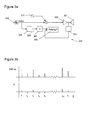
- Figure 3a depicts a further embodiment 300 of the invention comprising an apparatus configured to determine the polarity of a loudspeaker.
- the apparatus comprises: a signal generator 311; an audio input 325; an amplifier 322; a loudspeaker 301 (full-range or multi-way); an impedance determining module 302; a polarity determining module 303, which in this case is a processor; a reference signal provider 326; and a time delay 327.
- This embodiment is configured to determine the absolute polarity of a loudspeaker during normal operation of the amplifier and loudspeaker. This may remove the need for a dedicated calibration procedure.
- the signal generator 311 is configured to generate a sinusoidal pilot tone (with a predetermined frequency such as that described in the first embodiment). This pilot tone is added to the audio input 325.
- the composite input signal (comprising the audio signal and the pilot signal) is amplified by an amplifier 322, and sent to the loudspeaker.
- the magnitude of the electrical impedance at the pilot frequency, ( Z ( fpilot )), is determined repeatedly at predetermined time intervals ( t 1 to t N ), yielding a time signal that is related to the varying electrical impedance of the loudspeaker (the impedance in this case is changing because the position of the diaphragm is moving with the audio input, and the impedance at high frequencies is mostly related to changes in inductance, which varies with diaphragm displacement). That is, in this case, the determined impedance values correspond to different input signal portions (because the audio signal changes with time).
- the Z ( fpilot ) signal (which corresponds to how the impedance changes with time) is compared to a reference signal 328, provided by the reference signal provider 326, which may be delayed by delay module 327 (" ⁇ ").
- the reference signal 328 is the expected diaphragm displacement signal that is obtained from the audio signal (using loudspeaker voltage-to-excursion prediction block 326.
- This prediction block may consist of a filter that corresponds to the expected voltage-to-excursion transfer function and may receive the audio signal as input.
- the transfer function may be fixed, or may be made adaptive to account for possible changes in loudspeaker behaviour (due to temperature or ageing
- the apparatus comprises a polarity determining module 303 configured to determine whether the impedance signal, Z ( fpilot ), varies in phase or counterphase with the reference signal 328 (e.g. whether the impedance signal increases or decreases when the reference signal increases). If the impedance signal, Z ( fpilot ), varies in phase with the reference signal 328, then the processor is configured to determine that the loudspeaker has a reverse polarity. If the impedance signal varies out of phase with the reference signal 328, then the polarity determining module 303 is configured to determine that the loudspeaker has a normal polarity. A schematic plot of the determined impedance signal and reference signal is shown in figure 3b for a loudspeaker with reverse polarity.
- the Z ( fpilot ) signal may be compared to the audio input signal (or a filtered version thereof) at the appropriate sampling rate (sampling rate conversion may be necessary to match the reference values to the predetermined time intervals of the determined impedance values).
- the audio signal would be appropriately delayed by the delay module 327 (" ⁇ ") to be time-aligned to the signal that is related to the varying electrical impedance.
- the absolute polarity can be determined, for example, by computing the peak in the cross-correlation function of the determined impedance values with the reference audio signal. A negative peak, in this case, would correspond to normal polarity.
- the reference signal 328 may comprise impedance values (each reference impedance value corresponding to different input signal portions) determined for another loudspeaker that is being excited by the same composite input signal (audio signal 325 with pilot tone 311 added). If the impedance signal, Z ( fpilot ), varies in phase with the reference signal 328 then the processor is configured to determine that the two loudspeaker have the same polarity. If the impedance signal varies out of phase with the reference signal 328, then the polarity determining module 303 is configured to determine that the two loudspeakers have different polarities.
- Figure 4a depicts a further embodiment 400 of the invention comprising an apparatus configured to determine the relative polarity of a plurality of loudspeakers.
- the apparatus comprises a signal generator 411 configured to provide an input signal to a first loudspeaker 401 and a second loudspeaker 431 via respective first and second amplifiers 422, 423.
- the impedance of the first and second loudspeakers 401, 431 are each determined by respective first and second impedance determining modules 405, 406.
- the impedance determining modules each comprise a current sensing means to measure the current passing through the loudspeaker; a voltage sensing means to measure the voltage across the loudspeaker; and a processor configured to determine the ratio of the voltage to the current, thereby determining the impedance.
- the apparatus further comprises a polarity determining module 403 configured to determine the relative polarity of the loudspeakers 401, 431 based on the impedance values provided by the first and second impedance determining modules 405, 406.
- the apparatus is configured such that the relative phase of two (or more) loudspeakers are determined in a calibration phase (as shown in figure 4b ).
- the electrical impedance function of a loudspeaker changes across the entire frequency spectrum as a function of the diaphragm displacement.
- the apparatus is configured to provide a series of test signals comprising different predetermined frequencies, f 1 -f N , to each loudspeaker 401, 431.
- the apparatus is configured to measure the magnitude of the impedance of the loudspeaker at that frequency in the absence and the presence of the DC voltage.
- the impedances are stored by the polarity determining module 403.
- the polarity determining module is configured to compare the variation in values that are caused by a fixed change in diaphragm displacement for both loudspeakers. Assuming the loudspeakers are similar, the variation due to the fixed diaphragm displacement should be similar to each other if all loudspeakers are connected with the same polarity. A large difference between loudspeaker impedance values would indicate a different polarity. Therefore, in this case, the polarity determining module is configured to determine whether the variation in impedance across the multiple frequencies that are caused by a fixed loudspeaker diaphragm displacement is similar. If they are similar, the polarity determining module will determine that the polarities are the same, and if not, the polarity determining module will determine that the polarities are different.
- the relative phase of the loudspeakers is more important than the absolute phase. That is, when the diaphragms of a plurality of loudspeakers are moving in the same direction for a given signal, attenuation between loudspeakers is diminished.
- embodiments may be used in audio amplifiers for home or automotive settings, where the polarity of the loudspeakers is important for a high-quality audio reproduction.
- the proposed invention can also be used in mobile phones, where either the polarity is required to know the absolute polarity of a single loudspeaker (which can be important in applications involving loudspeaker modelling), or the relative polarity of multiple loudspeakers needs to be determined for good audio reproduction.
- any components that are described herein as being “coupled” or “connected” could be directly or indirectly coupled or connected. That is, one or more components could be located between two components that are said to be coupled or connected whilst still enabling the required functionality to be achieved.
Landscapes
- Physics & Mathematics (AREA)
- Engineering & Computer Science (AREA)
- Acoustics & Sound (AREA)
- Signal Processing (AREA)
- Health & Medical Sciences (AREA)
- General Health & Medical Sciences (AREA)
- Otolaryngology (AREA)
- Circuit For Audible Band Transducer (AREA)
- General Physics & Mathematics (AREA)
Abstract
determining one or more impedance values of a loudspeaker; and determining the polarity of a loudspeaker based on the one or more impedance values. Apparatus and computer program implementing the method above.
Description
- This invention relates to loudspeakers, and particularly, but not exclusively to detecting the polarity of a loudspeaker.
- Loudspeakers generally comprise a diaphragm (or cone), connected to a rigid frame, via a flexible suspension that constrains a voice coil to move axially through a cylindrical magnetic gap. When an electrical signal is applied to the voice coil, a magnetic field is created by the electric current in the voice coil, making it a variable electromagnet. The coil and the driver's magnetic system interact, generating a mechanical force that causes the coil (and thus, the attached diaphragm) to move back and forth, thereby reproducing sound under the control of the applied electrical signal coming from the amplifier.
- The polarity of a loudspeaker determines whether the loudspeaker diaphragm (e.g. cone) moves out or in relative to the voltage polarity of the signal.
- In audio systems with multiple loudspeakers, it may be important to connect the loudspeakers in phase with each other (i.e., with the same polarity). If they are connected incorrectly, the audio signal will not be reproduced faithfully. For example, if two loudspeakers with different polarity receive the same signal, at any given instant one loudspeaker diaphragm (e.g. cone) will be moving out and the other moving in. This may cause phase cancellations at certain frequencies and may be very noticeable. That is, the stereo image may be distorted or the low frequencies may be attenuated (because the low frequencies of one loudspeaker may cancel those of another). Therefore, ensuring that loudspeakers are connected with the correct polarity may mitigate the effects of the loudspeaker diaphragm of different loudspeakers moving in counterphase (or anti-phase).
- Because the polarity of the loudspeakers may affect the audio output signal, it may be possible to measure the polarity using, for example, a microphone. However, this may require additional equipment and may be affected by other acoustic effects (e.g. by the shape of the room).
- According to a first aspect of the invention, there is provided a method comprising the steps of:
- determining one or more impedance values of a loudspeaker; and
- determining the polarity of a loudspeaker based on the one or more impedance values.
- The method may comprise the step of determining a plurality of impedance values of a loudspeaker, each of the impedance values corresponding to a different input signal or input signal portions provided to the loudspeaker. The signal portions may comprise different temporal segments of a signal.
- The step of determining the polarity of the loudspeaker may comprise calculating the difference between a first impedance corresponding to a first input signal and a second impedance corresponding to a second input signal, wherein
- the first input signal comprises a signal with a predetermined frequency, and
- the second input signal comprises a signal with the predetermined frequency and an additional direct current signal.
- The method may comprise the step of determining a plurality of impedance values for different portions of an input signal, the input signal comprising:
- a pilot signal with a predetermined frequency; and
- an audio signal.
- The step of determining the polarity of the loudspeaker may comprise comparing the determined one or more impedance values with corresponding reference values.
- The corresponding reference values may comprise at least one of:
- expected impedance values;
- impedance values determined for another loudspeaker;
- corresponding input audio signal values; and
- a processed version of corresponding input audio signal values.
- The comparison may comprise temporal cross-correlation of the determined one or more impedance values and the corresponding reference values.
- The step of determining the one or more impedance values may comprise determining a plurality of impedance values for a number of different input signals, each input signal being distinguished by at least one of: having a different frequency; and comprising a different DC-value.
- The step of determining the polarity of the loudspeaker may comprise comparing the plurality of impedance values with corresponding impedance values measured for a different loudspeaker.
- The step of determining each impedance value may comprise measuring:
- the voltage across the loudspeaker voice coil; and
- the current flowing through the loudspeaker voice coil.
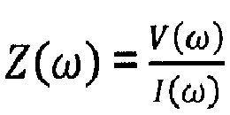
- In particular, the electrical impedance of a loudspeaker may be measured using the ratio of the voltage across and the current flowing into the loudspeaker voice coil:

where V(w), I(w) and Z(w) are the voltage, current and electrical impedance function at frequency w. - The method may comprise the step of determining the relative polarity of the loudspeaker with respect to other loudspeakers in a loudspeaker system.
- According to a further aspect, there is provided an apparatus comprising:
- impedance determining module configured to determine one or more impedance values of a loudspeaker; and
- polarity determining module configured to determine the polarity of a loudspeaker based on the one or more impedance values.
- It will be appreciated that the apparatus may determine the impedance and/or polarity using one of the described methods.
- The polarity determining module may comprise a processor.
- The impedance determining module may comprise:
- a current sensing means to measure the current passing through the loudspeaker;
- a voltage sensing means to measure the voltage across the loudspeaker; and
- a processor configured to determine the ratio of the voltage to the current.
- The impedance determining module may consist of a voltage sensing means (such as a voltage sense amplifier), a current sensing means (such as a current sense amplifier the output voltage of which may be proportional to the current; a current sense or shunt resistance in series with the load may be used to convert the load current to a small voltage, which is amplified by the current sense amplifier) and a means for computing the impedance according to
- The apparatus may, or may not, comprise a signal generator configured to generate a predetermined signal, and wherein the apparatus is configured to determine a plurality of impedance values of a loudspeaker, each of the impedance values corresponding to a different input signal or input signal portion provided to the loudspeaker.
- The apparatus may or may not comprise the loudspeaker.
- According to a further aspect, there is provided a computer program comprising computer program code configured to:
- determine one or more impedance values of a loudspeaker; and
- determine the polarity of a loudspeaker based on the one or more impedance values.
- Embodiments will now be described by way of non-limiting examples with reference to the accompanying figures, in which:
-
Figure 1 illustrates a loudspeaker system; -
Figures 2a-2b illustrate an apparatus according to an embodiment of the invention configured to determine the absolute polarity of a loudspeaker; -
Figures 3a-3b illustrate a second embodiment of the invention configured to determine the absolute polarity of a loudspeaker; and -
Figures 4a-4b illustrate a third embodiment of the invention configured to determine the relative polarity of a plurality of loudspeakers. - A
loudspeaker system 100 is illustrated infigure 1 which comprises twoloudspeakers dualchannel amplifier 103 with twoloudspeakers loudspeaker 101 with normal polarity; theother loudspeaker 102 with reverse polarity. - Generally, for a loudspeaker that is connected with normal polarity, a positive voltage results in an outward movement of the loudspeaker diaphragm, and a negative voltage results in an inward movement of the diaphragm.
- It has been realised that the electrical impedance of a loudspeaker changes as a function of the diaphragm displacement. This is because the impedance of the loudspeaker is affected by changes in other loudspeaker parameters (such as the BI-factor, the inductance and the stiffness) which in turn are affected by the diaphragm displacement. Therefore, movement of the diaphragm effects the electrical impedance of the loudspeaker.
- This invention relates to a method and system to determine the polarity of a single or multiple loudspeakers by analysing the electrical impedance variations of the loudspeaker(s) and/or variations in the diaphragm displacement (or related signals).
-
Figure 2a depicts afirst embodiment 200 of the invention, comprising an apparatus configured to determine the polarity of a loudspeaker. In this case, the apparatus comprises: asignal generator 211; anamplifier 222; aloudspeaker 201; animpedance determining module 202; and a polarity determining module, which in this case is aprocessor 203. - The impedance determining module may consist of a voltage sensing means (such as a voltage sense amplifier), a current sensing means (such as a current sense amplifier) and a means for computing the impedance according to

- Using this apparatus, a calibration method (shown in
figure 2b ) is used to determine the absolute polarity of theloudspeaker 201 by determining whether the loudspeaker impedance is increased or decreased as a function of a positive DC voltage. The inductance of a loudspeaker that is connected with normal polarity is expected to decrease for an outward movement of the loudspeaker, and so, because the impedance of the loudspeaker is related to its inductance, the absolute polarity of a loudspeaker can be determined using measurements of the impedance. The impedance of a loudspeaker consists of, among others, a resistance, a motor impedance (resonance peak) and an inductance. The relative components making up the impedance vary with frequency. For example, the impedance is predominantly determined by the inductance at higher frequencies. - In this case, the effect of the loudspeaker impedance variation is measured at frequencies where the motor impedance is small, e.g., two octaves higher than the resonance frequency of the loudspeaker. In that frequency region, the effect of the variation of many other loudspeaker parameters (e.g., those constituting the motor impedance) is expected to be very small, and the loudspeaker impedance is predominantly determined by its inductance (which varies with diaphragm displacement). It will be appreciated that other embodiments may use other frequencies.
- The calibration method comprises providing a first test signal to the
loudspeaker 201 comprising a signal with a predetermined frequency. The first test signal may, for example, comprise a small amplitude sine wave at the predetermined frequency, ωo (say, two octaves above the resonance frequency of the loudspeaker). Other non-sinusoidal waveforms may also be used provided that there is a non-zero signal component at the predetermined frequency. In this case, the signal is provided using thesignal generator 211 and amplified using theamplifier 222. When the first test signal is being provided to theloudspeaker 201 the magnitude of the first electrical impedance is determined (e.g. by being measured or by estimation) at the predetermined frequency corresponding to the first test signal using the impedance determining module. In this case, the impedance determining module is configured to determine the first electrical impedance Z1(ωo ) by measuring the amplitudes of voltage V 1(ωo ) and current I 1(ωo ) at that frequency ωo (using voltage sensing and current sensing amplifiers, converting the signals to the digital domain and using, e.g., a DFT to compute the amplitudes at the given frequency) and computing the ratio,
- The method further comprises applying a second test signal, which consists of the first test signal (i.e. also comprising a signal with a predetermined frequency ωo ) with a positive DC voltage signal added to it. When the second test signal is being provided to the
loudspeaker 201 by thesignal generator 211 andamplifier 222, the magnitude of a second electrical impedance corresponding to the second test signal is determined (e.g. by being measured or by estimation) at the predetermined frequency by theimpedance determining module 202. As described before, the second electrical impedance Z2(ωo ) is determined by estimating the amplitudes of voltage V2(ωo ) and current I 2(wo ) at the predetermined frequency ωo (using voltage sensing and current sensing amplifiers) and computing the ratio
- It will be appreciated that the provision and measurement corresponding to the second test signal may be carried out before or after the provision and measurement corresponding to the first test signal.
- The first and second impedance values are received from the impedance determining module by the polarity determining module (which in this case is a processor 203). The processor is configured to determine which of the first and second impedance values is the larger. The polarity sensing means is configured to determine that the loudspeaker has normal polarity if the amplitude of the second electrical impedance is smaller than that of the first. Conversely, the polarity sensing means is configured to determine that the loudspeaker has reverse polarity if the amplitude of the second electrical impedance is larger than the first electrical impedance. In this case, the processor 203 (e.g. a comparator) is used to determine which of the impedence values is larger.
- Other example embodiments are configured such that if the electrical impedances are identical (or within a predetermined threshold) the apparatus is configured to repeat the calibration method with a larger DC voltage in the second test signal.
- It will be appreciated that the method may be performed with a negative DC voltage. This method can be used for full-range loudspeakers or multi-way loudspeakers.
-
Figure 3a depicts afurther embodiment 300 of the invention comprising an apparatus configured to determine the polarity of a loudspeaker. In this case, the apparatus comprises: asignal generator 311; anaudio input 325; anamplifier 322; a loudspeaker 301 (full-range or multi-way); animpedance determining module 302; apolarity determining module 303, which in this case is a processor; areference signal provider 326; and atime delay 327. - This embodiment is configured to determine the absolute polarity of a loudspeaker during normal operation of the amplifier and loudspeaker. This may remove the need for a dedicated calibration procedure.
- In this case, the
signal generator 311 is configured to generate a sinusoidal pilot tone (with a predetermined frequency such as that described in the first embodiment). This pilot tone is added to theaudio input 325. The composite input signal (comprising the audio signal and the pilot signal) is amplified by anamplifier 322, and sent to the loudspeaker. When the composite input is being provided, theimpedance determining module 302 is configured to measure the voltage and current components at the predetermined frequency, and calculate the ratio which gives the impedance,
- In this case, the Z(fpilot) signal (which corresponds to how the impedance changes with time) is compared to a
reference signal 328, provided by thereference signal provider 326, which may be delayed by delay module 327 ("Δ"). In this case, thereference signal 328 is the expected diaphragm displacement signal that is obtained from the audio signal (using loudspeaker voltage-to-excursion prediction block 326. This prediction block may consist of a filter that corresponds to the expected voltage-to-excursion transfer function and may receive the audio signal as input. The transfer function may be fixed, or may be made adaptive to account for possible changes in loudspeaker behaviour (due to temperature or ageing - In this case, the apparatus comprises a
polarity determining module 303 configured to determine whether the impedance signal, Z(fpilot), varies in phase or counterphase with the reference signal 328 (e.g. whether the impedance signal increases or decreases when the reference signal increases). If the impedance signal, Z(fpilot), varies in phase with thereference signal 328, then the processor is configured to determine that the loudspeaker has a reverse polarity. If the impedance signal varies out of phase with thereference signal 328, then thepolarity determining module 303 is configured to determine that the loudspeaker has a normal polarity. A schematic plot of the determined impedance signal and reference signal is shown infigure 3b for a loudspeaker with reverse polarity. - It will be appreciated that, in other embodiments, the Z(fpilot) signal may be compared to the audio input signal (or a filtered version thereof) at the appropriate sampling rate (sampling rate conversion may be necessary to match the reference values to the predetermined time intervals of the determined impedance values). In such an embodiment, the audio signal would be appropriately delayed by the delay module 327 ("Δ") to be time-aligned to the signal that is related to the varying electrical impedance. In this case, the absolute polarity can be determined, for example, by computing the peak in the cross-correlation function of the determined impedance values with the reference audio signal. A negative peak, in this case, would correspond to normal polarity.
- It will be appreciated that, in another embodiment, the
reference signal 328 may comprise impedance values (each reference impedance value corresponding to different input signal portions) determined for another loudspeaker that is being excited by the same composite input signal (audio signal 325 withpilot tone 311 added). If the impedance signal, Z(fpilot), varies in phase with thereference signal 328 then the processor is configured to determine that the two loudspeaker have the same polarity. If the impedance signal varies out of phase with thereference signal 328, then thepolarity determining module 303 is configured to determine that the two loudspeakers have different polarities. -
Figure 4a depicts afurther embodiment 400 of the invention comprising an apparatus configured to determine the relative polarity of a plurality of loudspeakers. In this case, the apparatus comprises asignal generator 411 configured to provide an input signal to afirst loudspeaker 401 and asecond loudspeaker 431 via respective first andsecond amplifiers second loudspeakers impedance determining modules polarity determining module 403 configured to determine the relative polarity of theloudspeakers impedance determining modules - In this case the apparatus is configured such that the relative phase of two (or more) loudspeakers are determined in a calibration phase (as shown in
figure 4b ). The electrical impedance function of a loudspeaker changes across the entire frequency spectrum as a function of the diaphragm displacement. If the electrical impedance is measured for multiple frequencies, or over a portion of the frequency spectrum (e.g., from 5 Hz up to half the sampling rate) with and without the addition of a positive DC voltage (due to which there will be a fixed change of the loudspeaker diaphragm displacement, which in turn, changes the impedance of the loudspeaker), a variation of the electrical impedance function can be determined that is caused by a fixed change in loudspeaker diaphragm displacement. In this case, the apparatus is configured to provide a series of test signals comprising different predetermined frequencies, f1-fN, to eachloudspeaker polarity determining module 403. - When all of the frequencies have been provided and the corresponding impedances measured in the absence and the presence of the DC voltage, the polarity determining module is configured to compare the variation in values that are caused by a fixed change in diaphragm displacement for both loudspeakers. Assuming the loudspeakers are similar, the variation due to the fixed diaphragm displacement should be similar to each other if all loudspeakers are connected with the same polarity. A large difference between loudspeaker impedance values would indicate a different polarity. Therefore, in this case, the polarity determining module is configured to determine whether the variation in impedance across the multiple frequencies that are caused by a fixed loudspeaker diaphragm displacement is similar. If they are similar, the polarity determining module will determine that the polarities are the same, and if not, the polarity determining module will determine that the polarities are different.
- In certain embodiments, the relative phase of the loudspeakers is more important than the absolute phase. That is, when the diaphragms of a plurality of loudspeakers are moving in the same direction for a given signal, attenuation between loudspeakers is diminished.
- It will be appreciated that embodiments may be used in audio amplifiers for home or automotive settings, where the polarity of the loudspeakers is important for a high-quality audio reproduction. The proposed invention can also be used in mobile phones, where either the polarity is required to know the absolute polarity of a single loudspeaker (which can be important in applications involving loudspeaker modelling), or the relative polarity of multiple loudspeakers needs to be determined for good audio reproduction.
- Any components that are described herein as being "coupled" or "connected" could be directly or indirectly coupled or connected. That is, one or more components could be located between two components that are said to be coupled or connected whilst still enabling the required functionality to be achieved.
Claims (15)
- A method comprising the steps of:determining one or more impedance values of a loudspeaker; anddetermining the polarity of a loudspeaker based on the one or more impedance values.
- The method of claim 1, wherein the method comprises the step of determining a plurality of impedance values of a loudspeaker, each of the impedance values corresponding to a different input signal or input signal portions provided to the loudspeaker.
- The method of claim 1, wherein the step of determining the polarity of the loudspeaker comprises calculating the difference between a first impedance corresponding to a first input signal and a second impedance corresponding to a second input signal, whereinthe first input signal comprises a signal with a predetermined frequency, andthe second input signal comprises a signal with the predetermined frequency and an additional direct current signal.
- The method of claim 1, wherein the method comprises the step of determining a plurality of impedance values for different portions of an input signal, the input signal comprising:a pilot signal with a predetermined frequency; andan audio signal.
- The method of claim 4, wherein the step of determining the polarity of the loudspeaker comprises comparing the determined one or more impedance values with corresponding reference values.
- The method of claim 5, wherein the corresponding reference values comprise at least one of:predetermined expected impedance values;impedance values determined for another loudspeaker;corresponding input audio signal values; anda processed version of corresponding input audio signal values.
- The method of claim 5 or 6, wherein the comparison comprises temporal cross-correlation of the determined one or more impedance values and the corresponding reference values.
- The method of claim 1, wherein the step of determining the one or more impedance values comprises determining a plurality of impedance values for a number of different input signals, each input signal being distinguished by at least one of: having a different frequency; and comprising a different DC-value.
- The method of claim 8, wherein the step of determining the polarity of the loudspeaker comprises comparing the plurality of impedance values with corresponding impedance values measured for a different loudspeaker.
- The method of any preceding claim, wherein the step of determining each impedance value comprises measuring:the voltage across the loudspeaker voice coil; andthe current flowing through the loudspeaker voice coil.
- The method of any preceding claim, wherein the method comprises the step of determining the relative polarity of the loudspeaker with respect to other loudspeakers in a loudspeaker system.
- An apparatus comprising:impedance determining module configured to determine one or more impedance values of a loudspeaker; andpolarity determining module configured to determine the polarity of a loudspeaker based on the one or more impedance values.
- The apparatus of claim 12, wherein the impedance determining module comprises:current sensing means to measure the current passing through the loudspeaker;a voltage sensing means to measure the voltage across the loudspeaker; anda processor configured to determine the ratio of the voltage to the current.
- The apparatus of any of claim 12-13, wherein the apparatus comprises a signal generator configured to generate a predetermined signal, and wherein the apparatus is configured to determine a plurality of impedance values of a loudspeaker, each of the impedance values corresponding to a different input signal or input signal portion provided to the loudspeaker.
- A computer program comprising computer program code configured to:determine one or more impedance values of a loudspeaker; anddetermine the polarity of a loudspeaker based on the one or more impedance values.
Priority Applications (3)
| Application Number | Priority Date | Filing Date | Title |
|---|---|---|---|
| EP13192918.4A EP2874408B1 (en) | 2013-11-14 | 2013-11-14 | Loudspeaker polarity detector |
| US14/508,569 US9357322B2 (en) | 2013-11-14 | 2014-10-07 | Loudspeaker polarity detector |
| CN201410645602.2A CN104640052B (en) | 2013-11-14 | 2014-11-12 | Loudspeaker polarity detector |
Applications Claiming Priority (1)
| Application Number | Priority Date | Filing Date | Title |
|---|---|---|---|
| EP13192918.4A EP2874408B1 (en) | 2013-11-14 | 2013-11-14 | Loudspeaker polarity detector |
Publications (2)
| Publication Number | Publication Date |
|---|---|
| EP2874408A1 true EP2874408A1 (en) | 2015-05-20 |
| EP2874408B1 EP2874408B1 (en) | 2016-05-25 |
Family
ID=49619813
Family Applications (1)
| Application Number | Title | Priority Date | Filing Date |
|---|---|---|---|
| EP13192918.4A Active EP2874408B1 (en) | 2013-11-14 | 2013-11-14 | Loudspeaker polarity detector |
Country Status (3)
| Country | Link |
|---|---|
| US (1) | US9357322B2 (en) |
| EP (1) | EP2874408B1 (en) |
| CN (1) | CN104640052B (en) |
Families Citing this family (4)
| Publication number | Priority date | Publication date | Assignee | Title |
|---|---|---|---|---|
| EP3010251B1 (en) * | 2014-10-15 | 2019-11-13 | Nxp B.V. | Audio system |
| US9565505B2 (en) * | 2015-06-17 | 2017-02-07 | Intel IP Corporation | Loudspeaker cone excursion estimation using reference signal |
| CN112887893A (en) * | 2021-02-03 | 2021-06-01 | 北京小米移动软件有限公司 | Loudspeaker using method, device and medium |
| CN120857057A (en) * | 2025-06-20 | 2025-10-28 | 深圳引望智能技术有限公司 | Detection method and device |
Citations (4)
| Publication number | Priority date | Publication date | Assignee | Title |
|---|---|---|---|---|
| US5319714A (en) * | 1992-09-23 | 1994-06-07 | Mctaggart James E | Audio phase polarity test system |
| US6681019B1 (en) * | 1998-09-22 | 2004-01-20 | Yamaha Corporation | Polarity determining circuit for loudspeakers, an audio circuit having a function of determining polarities of loudspeakers, and an audio circuit having functions of determining polarities of loudspeakers and switching the polarities |
| US20100239099A1 (en) * | 2009-03-18 | 2010-09-23 | Texas Instruments Incorporated | Method and Apparatus for Polarity Detection of Loudspeaker |
| EP2453669A1 (en) * | 2010-11-16 | 2012-05-16 | Nxp B.V. | Control of a loudspeaker output |
Family Cites Families (9)
| Publication number | Priority date | Publication date | Assignee | Title |
|---|---|---|---|---|
| US3067297A (en) * | 1960-02-26 | 1962-12-04 | Philco Corp | Apparatus for determining the polarities of stereophonic channel connections at anyselected point |
| US4908868A (en) * | 1989-02-21 | 1990-03-13 | Mctaggart James E | Phase polarity test instrument and method |
| US20060050891A1 (en) | 2004-09-07 | 2006-03-09 | Sunil Bharitkar | Method for automatic loudspeaker polarity determination through loudspeaker-room acoustic responses |
| US20060062399A1 (en) * | 2004-09-23 | 2006-03-23 | Mckee Cooper Joel C | Band-limited polarity detection |
| JP4240228B2 (en) * | 2005-04-19 | 2009-03-18 | ソニー株式会社 | Acoustic device, connection polarity determination method, and connection polarity determination program |
| CN101365261B (en) * | 2008-09-26 | 2013-02-06 | 嘉兴中科声学科技有限公司 | Method for speaker parameter fast detection by analog synchronization signal and detection system |
| US8831235B2 (en) * | 2009-02-26 | 2014-09-09 | Pioneer Corporation | Speaker polarity determination device |
| CN102790942B (en) * | 2012-08-24 | 2015-07-15 | 惠州市金山电子有限公司 | Loudspeaker testing device |
| US8989397B2 (en) * | 2013-01-14 | 2015-03-24 | Kyounghee Lee | System and method for high reliability sound production |
-
2013
- 2013-11-14 EP EP13192918.4A patent/EP2874408B1/en active Active
-
2014
- 2014-10-07 US US14/508,569 patent/US9357322B2/en active Active
- 2014-11-12 CN CN201410645602.2A patent/CN104640052B/en active Active
Patent Citations (4)
| Publication number | Priority date | Publication date | Assignee | Title |
|---|---|---|---|---|
| US5319714A (en) * | 1992-09-23 | 1994-06-07 | Mctaggart James E | Audio phase polarity test system |
| US6681019B1 (en) * | 1998-09-22 | 2004-01-20 | Yamaha Corporation | Polarity determining circuit for loudspeakers, an audio circuit having a function of determining polarities of loudspeakers, and an audio circuit having functions of determining polarities of loudspeakers and switching the polarities |
| US20100239099A1 (en) * | 2009-03-18 | 2010-09-23 | Texas Instruments Incorporated | Method and Apparatus for Polarity Detection of Loudspeaker |
| EP2453669A1 (en) * | 2010-11-16 | 2012-05-16 | Nxp B.V. | Control of a loudspeaker output |
Non-Patent Citations (1)
| Title |
|---|
| KLIPPEL, WOLFGANG, AES 108TH CONVENTION, PARIS, FRANCE., 5109, 19 February 2000 (2000-02-19) - 22 February 2000 (2000-02-22), pages 1 - 36, XP040371438 * |
Also Published As
| Publication number | Publication date |
|---|---|
| EP2874408B1 (en) | 2016-05-25 |
| CN104640052B (en) | 2020-02-11 |
| US9357322B2 (en) | 2016-05-31 |
| US20150131806A1 (en) | 2015-05-14 |
| CN104640052A (en) | 2015-05-20 |
Similar Documents
| Publication | Publication Date | Title |
|---|---|---|
| EP2879401B1 (en) | Determining the temperature of a loudspeaker voice coil | |
| EP3026930B1 (en) | Method, system and apparatus for loudspeaker excursion domain processing | |
| US9414160B2 (en) | Method, system and apparatus for loudspeaker excursion domain processing | |
| US9264829B2 (en) | Device and method for detecting force factor of loudspeaker | |
| US9578416B2 (en) | Control of a loudspeaker output | |
| US9319777B2 (en) | Drive control circuit for vibration speaker | |
| CN109951787B (en) | Loudspeaker parameter prediction system | |
| US9955261B2 (en) | Method and apparatus for adjusting a cross-over frequency of a loudspeaker | |
| CN106031197B (en) | Acoustic processing equipment, acoustic processing method and acoustic processing program | |
| CN105659631B (en) | Sound field measurement apparatus and sound field measuring method | |
| CN105375854A (en) | Voice coil motor and speaker controller | |
| US9357322B2 (en) | Loudspeaker polarity detector | |
| WO2009134537A2 (en) | Detecting a loudspeaker configuration | |
| US20140023198A1 (en) | Method and circuit for testing an audio high-frequency loudspeaker being part of a loudspeaker system | |
| CN109151667B (en) | Signal processing method, device and loudspeaker | |
| US9510119B2 (en) | Method and device for detecting function of loudspeaker module | |
| KR101358182B1 (en) | Method for measuring frequency characteristic and rising edge of impulse response, and sound field correcting apparatus | |
| CN109709559B (en) | Ultrasonic sensor and control method | |
| KR101757362B1 (en) | Pink noise output method for inspected of acoustic apparatus | |
| US11570563B1 (en) | Method for estimating fundamental resonance frequency of loudspeaker and associated loudspeaker controller | |
| Klippel et al. | Fast measurement of motor suspension nonlinearities in loudspeaker manufacturing | |
| JP4830343B2 (en) | Automatic sound field correction system and automatic sound field correction method | |
| Ochiai et al. | Impulse response measurement with constant signal-to-noise ratio over a wide frequency range | |
| Novak et al. | Static and Dynamic Measurement of a Magnet-only Loudspeaker | |
| Faifer et al. | A novel, cost-effective method for loudspeakers parameters measurement under non-linear conditions |
Legal Events
| Date | Code | Title | Description |
|---|---|---|---|
| PUAI | Public reference made under article 153(3) epc to a published international application that has entered the european phase |
Free format text: ORIGINAL CODE: 0009012 |
|
| 17P | Request for examination filed |
Effective date: 20140327 |
|
| AK | Designated contracting states |
Kind code of ref document: A1 Designated state(s): AL AT BE BG CH CY CZ DE DK EE ES FI FR GB GR HR HU IE IS IT LI LT LU LV MC MK MT NL NO PL PT RO RS SE SI SK SM TR |
|
| AX | Request for extension of the european patent |
Extension state: BA ME |
|
| 17Q | First examination report despatched |
Effective date: 20150625 |
|
| RBV | Designated contracting states (corrected) |
Designated state(s): AL AT BE BG CH CY CZ DE DK EE ES FI FR GB GR HR HU IE IS IT LI LT LU LV MC MK MT NL NO PL PT RO RS SE SI SK SM TR |
|
| GRAP | Despatch of communication of intention to grant a patent |
Free format text: ORIGINAL CODE: EPIDOSNIGR1 |
|
| INTG | Intention to grant announced |
Effective date: 20160114 |
|
| GRAS | Grant fee paid |
Free format text: ORIGINAL CODE: EPIDOSNIGR3 |
|
| GRAA | (expected) grant |
Free format text: ORIGINAL CODE: 0009210 |
|
| AK | Designated contracting states |
Kind code of ref document: B1 Designated state(s): AL AT BE BG CH CY CZ DE DK EE ES FI FR GB GR HR HU IE IS IT LI LT LU LV MC MK MT NL NO PL PT RO RS SE SI SK SM TR |
|
| REG | Reference to a national code |
Ref country code: GB Ref legal event code: FG4D |
|
| REG | Reference to a national code |
Ref country code: CH Ref legal event code: EP |
|
| REG | Reference to a national code |
Ref country code: IE Ref legal event code: FG4D Ref country code: AT Ref legal event code: REF Ref document number: 803180 Country of ref document: AT Kind code of ref document: T Effective date: 20160615 |
|
| REG | Reference to a national code |
Ref country code: DE Ref legal event code: R096 Ref document number: 602013007866 Country of ref document: DE |
|
| REG | Reference to a national code |
Ref country code: LT Ref legal event code: MG4D |
|
| REG | Reference to a national code |
Ref country code: NL Ref legal event code: MP Effective date: 20160525 |
|
| REG | Reference to a national code |
Ref country code: FR Ref legal event code: PLFP Year of fee payment: 4 |
|
| PG25 | Lapsed in a contracting state [announced via postgrant information from national office to epo] |
Ref country code: LT Free format text: LAPSE BECAUSE OF FAILURE TO SUBMIT A TRANSLATION OF THE DESCRIPTION OR TO PAY THE FEE WITHIN THE PRESCRIBED TIME-LIMIT Effective date: 20160525 Ref country code: NL Free format text: LAPSE BECAUSE OF FAILURE TO SUBMIT A TRANSLATION OF THE DESCRIPTION OR TO PAY THE FEE WITHIN THE PRESCRIBED TIME-LIMIT Effective date: 20160525 Ref country code: FI Free format text: LAPSE BECAUSE OF FAILURE TO SUBMIT A TRANSLATION OF THE DESCRIPTION OR TO PAY THE FEE WITHIN THE PRESCRIBED TIME-LIMIT Effective date: 20160525 Ref country code: NO Free format text: LAPSE BECAUSE OF FAILURE TO SUBMIT A TRANSLATION OF THE DESCRIPTION OR TO PAY THE FEE WITHIN THE PRESCRIBED TIME-LIMIT Effective date: 20160825 |
|
| REG | Reference to a national code |
Ref country code: AT Ref legal event code: MK05 Ref document number: 803180 Country of ref document: AT Kind code of ref document: T Effective date: 20160525 |
|
| PG25 | Lapsed in a contracting state [announced via postgrant information from national office to epo] |
Ref country code: SE Free format text: LAPSE BECAUSE OF FAILURE TO SUBMIT A TRANSLATION OF THE DESCRIPTION OR TO PAY THE FEE WITHIN THE PRESCRIBED TIME-LIMIT Effective date: 20160525 Ref country code: LV Free format text: LAPSE BECAUSE OF FAILURE TO SUBMIT A TRANSLATION OF THE DESCRIPTION OR TO PAY THE FEE WITHIN THE PRESCRIBED TIME-LIMIT Effective date: 20160525 Ref country code: RS Free format text: LAPSE BECAUSE OF FAILURE TO SUBMIT A TRANSLATION OF THE DESCRIPTION OR TO PAY THE FEE WITHIN THE PRESCRIBED TIME-LIMIT Effective date: 20160525 Ref country code: ES Free format text: LAPSE BECAUSE OF FAILURE TO SUBMIT A TRANSLATION OF THE DESCRIPTION OR TO PAY THE FEE WITHIN THE PRESCRIBED TIME-LIMIT Effective date: 20160525 Ref country code: PT Free format text: LAPSE BECAUSE OF FAILURE TO SUBMIT A TRANSLATION OF THE DESCRIPTION OR TO PAY THE FEE WITHIN THE PRESCRIBED TIME-LIMIT Effective date: 20160926 Ref country code: GR Free format text: LAPSE BECAUSE OF FAILURE TO SUBMIT A TRANSLATION OF THE DESCRIPTION OR TO PAY THE FEE WITHIN THE PRESCRIBED TIME-LIMIT Effective date: 20160826 |
|
| PG25 | Lapsed in a contracting state [announced via postgrant information from national office to epo] |
Ref country code: IT Free format text: LAPSE BECAUSE OF FAILURE TO SUBMIT A TRANSLATION OF THE DESCRIPTION OR TO PAY THE FEE WITHIN THE PRESCRIBED TIME-LIMIT Effective date: 20160525 |
|
| PG25 | Lapsed in a contracting state [announced via postgrant information from national office to epo] |
Ref country code: SK Free format text: LAPSE BECAUSE OF FAILURE TO SUBMIT A TRANSLATION OF THE DESCRIPTION OR TO PAY THE FEE WITHIN THE PRESCRIBED TIME-LIMIT Effective date: 20160525 Ref country code: CZ Free format text: LAPSE BECAUSE OF FAILURE TO SUBMIT A TRANSLATION OF THE DESCRIPTION OR TO PAY THE FEE WITHIN THE PRESCRIBED TIME-LIMIT Effective date: 20160525 Ref country code: EE Free format text: LAPSE BECAUSE OF FAILURE TO SUBMIT A TRANSLATION OF THE DESCRIPTION OR TO PAY THE FEE WITHIN THE PRESCRIBED TIME-LIMIT Effective date: 20160525 Ref country code: DK Free format text: LAPSE BECAUSE OF FAILURE TO SUBMIT A TRANSLATION OF THE DESCRIPTION OR TO PAY THE FEE WITHIN THE PRESCRIBED TIME-LIMIT Effective date: 20160525 Ref country code: RO Free format text: LAPSE BECAUSE OF FAILURE TO SUBMIT A TRANSLATION OF THE DESCRIPTION OR TO PAY THE FEE WITHIN THE PRESCRIBED TIME-LIMIT Effective date: 20160525 |
|
| PG25 | Lapsed in a contracting state [announced via postgrant information from national office to epo] |
Ref country code: SM Free format text: LAPSE BECAUSE OF FAILURE TO SUBMIT A TRANSLATION OF THE DESCRIPTION OR TO PAY THE FEE WITHIN THE PRESCRIBED TIME-LIMIT Effective date: 20160525 Ref country code: PL Free format text: LAPSE BECAUSE OF FAILURE TO SUBMIT A TRANSLATION OF THE DESCRIPTION OR TO PAY THE FEE WITHIN THE PRESCRIBED TIME-LIMIT Effective date: 20160525 Ref country code: AT Free format text: LAPSE BECAUSE OF FAILURE TO SUBMIT A TRANSLATION OF THE DESCRIPTION OR TO PAY THE FEE WITHIN THE PRESCRIBED TIME-LIMIT Effective date: 20160525 Ref country code: BE Free format text: LAPSE BECAUSE OF FAILURE TO SUBMIT A TRANSLATION OF THE DESCRIPTION OR TO PAY THE FEE WITHIN THE PRESCRIBED TIME-LIMIT Effective date: 20160525 |
|
| REG | Reference to a national code |
Ref country code: DE Ref legal event code: R097 Ref document number: 602013007866 Country of ref document: DE |
|
| PLBE | No opposition filed within time limit |
Free format text: ORIGINAL CODE: 0009261 |
|
| STAA | Information on the status of an ep patent application or granted ep patent |
Free format text: STATUS: NO OPPOSITION FILED WITHIN TIME LIMIT |
|
| 26N | No opposition filed |
Effective date: 20170228 |
|
| PG25 | Lapsed in a contracting state [announced via postgrant information from national office to epo] |
Ref country code: SI Free format text: LAPSE BECAUSE OF FAILURE TO SUBMIT A TRANSLATION OF THE DESCRIPTION OR TO PAY THE FEE WITHIN THE PRESCRIBED TIME-LIMIT Effective date: 20160525 |
|
| REG | Reference to a national code |
Ref country code: CH Ref legal event code: PL |
|
| PG25 | Lapsed in a contracting state [announced via postgrant information from national office to epo] |
Ref country code: LI Free format text: LAPSE BECAUSE OF NON-PAYMENT OF DUE FEES Effective date: 20161130 Ref country code: CH Free format text: LAPSE BECAUSE OF NON-PAYMENT OF DUE FEES Effective date: 20161130 |
|
| REG | Reference to a national code |
Ref country code: IE Ref legal event code: MM4A |
|
| PG25 | Lapsed in a contracting state [announced via postgrant information from national office to epo] |
Ref country code: LU Free format text: LAPSE BECAUSE OF NON-PAYMENT OF DUE FEES Effective date: 20161130 |
|
| REG | Reference to a national code |
Ref country code: FR Ref legal event code: PLFP Year of fee payment: 5 |
|
| PG25 | Lapsed in a contracting state [announced via postgrant information from national office to epo] |
Ref country code: IE Free format text: LAPSE BECAUSE OF NON-PAYMENT OF DUE FEES Effective date: 20161114 |
|
| PG25 | Lapsed in a contracting state [announced via postgrant information from national office to epo] |
Ref country code: HU Free format text: LAPSE BECAUSE OF FAILURE TO SUBMIT A TRANSLATION OF THE DESCRIPTION OR TO PAY THE FEE WITHIN THE PRESCRIBED TIME-LIMIT; INVALID AB INITIO Effective date: 20131114 |
|
| PG25 | Lapsed in a contracting state [announced via postgrant information from national office to epo] |
Ref country code: HR Free format text: LAPSE BECAUSE OF FAILURE TO SUBMIT A TRANSLATION OF THE DESCRIPTION OR TO PAY THE FEE WITHIN THE PRESCRIBED TIME-LIMIT Effective date: 20160525 Ref country code: MC Free format text: LAPSE BECAUSE OF FAILURE TO SUBMIT A TRANSLATION OF THE DESCRIPTION OR TO PAY THE FEE WITHIN THE PRESCRIBED TIME-LIMIT Effective date: 20160525 Ref country code: IS Free format text: LAPSE BECAUSE OF FAILURE TO SUBMIT A TRANSLATION OF THE DESCRIPTION OR TO PAY THE FEE WITHIN THE PRESCRIBED TIME-LIMIT Effective date: 20160525 Ref country code: MK Free format text: LAPSE BECAUSE OF FAILURE TO SUBMIT A TRANSLATION OF THE DESCRIPTION OR TO PAY THE FEE WITHIN THE PRESCRIBED TIME-LIMIT Effective date: 20160525 Ref country code: CY Free format text: LAPSE BECAUSE OF FAILURE TO SUBMIT A TRANSLATION OF THE DESCRIPTION OR TO PAY THE FEE WITHIN THE PRESCRIBED TIME-LIMIT Effective date: 20160525 |
|
| PG25 | Lapsed in a contracting state [announced via postgrant information from national office to epo] |
Ref country code: BG Free format text: LAPSE BECAUSE OF FAILURE TO SUBMIT A TRANSLATION OF THE DESCRIPTION OR TO PAY THE FEE WITHIN THE PRESCRIBED TIME-LIMIT Effective date: 20160525 |
|
| PG25 | Lapsed in a contracting state [announced via postgrant information from national office to epo] |
Ref country code: MT Free format text: LAPSE BECAUSE OF NON-PAYMENT OF DUE FEES Effective date: 20161114 |
|
| REG | Reference to a national code |
Ref country code: FR Ref legal event code: PLFP Year of fee payment: 6 |
|
| PG25 | Lapsed in a contracting state [announced via postgrant information from national office to epo] |
Ref country code: AL Free format text: LAPSE BECAUSE OF FAILURE TO SUBMIT A TRANSLATION OF THE DESCRIPTION OR TO PAY THE FEE WITHIN THE PRESCRIBED TIME-LIMIT Effective date: 20160525 Ref country code: TR Free format text: LAPSE BECAUSE OF FAILURE TO SUBMIT A TRANSLATION OF THE DESCRIPTION OR TO PAY THE FEE WITHIN THE PRESCRIBED TIME-LIMIT Effective date: 20160525 |
|
| REG | Reference to a national code |
Ref country code: DE Ref legal event code: R081 Ref document number: 602013007866 Country of ref document: DE Owner name: GOODIX TECHNOLOGY (HK) COMPANY LIMITED, CN Free format text: FORMER OWNER: NXP B.V., EINDHOVEN, NL |
|
| REG | Reference to a national code |
Ref country code: GB Ref legal event code: 732E Free format text: REGISTERED BETWEEN 20200917 AND 20200923 |
|
| PGFP | Annual fee paid to national office [announced via postgrant information from national office to epo] |
Ref country code: DE Payment date: 20251028 Year of fee payment: 13 |
|
| PGFP | Annual fee paid to national office [announced via postgrant information from national office to epo] |
Ref country code: GB Payment date: 20251030 Year of fee payment: 13 |
|
| PGFP | Annual fee paid to national office [announced via postgrant information from national office to epo] |
Ref country code: FR Payment date: 20251110 Year of fee payment: 13 |