EP2874283A1 - Provisional terminal holding structure, and resolver comprising provisional terminal holding structure - Google Patents
Provisional terminal holding structure, and resolver comprising provisional terminal holding structure Download PDFInfo
- Publication number
- EP2874283A1 EP2874283A1 EP13816393.6A EP13816393A EP2874283A1 EP 2874283 A1 EP2874283 A1 EP 2874283A1 EP 13816393 A EP13816393 A EP 13816393A EP 2874283 A1 EP2874283 A1 EP 2874283A1
- Authority
- EP
- European Patent Office
- Prior art keywords
- terminal
- welded portion
- cable
- winding
- pair
- Prior art date
- Legal status (The legal status is an assumption and is not a legal conclusion. Google has not performed a legal analysis and makes no representation as to the accuracy of the status listed.)
- Granted
Links
Images






Classifications
-
- H—ELECTRICITY
- H01—ELECTRIC ELEMENTS
- H01R—ELECTRICALLY-CONDUCTIVE CONNECTIONS; STRUCTURAL ASSOCIATIONS OF A PLURALITY OF MUTUALLY-INSULATED ELECTRICAL CONNECTING ELEMENTS; COUPLING DEVICES; CURRENT COLLECTORS
- H01R4/00—Electrically-conductive connections between two or more conductive members in direct contact, i.e. touching one another; Means for effecting or maintaining such contact; Electrically-conductive connections having two or more spaced connecting locations for conductors and using contact members penetrating insulation
- H01R4/02—Soldered or welded connections
- H01R4/027—Soldered or welded connections comprising means for positioning or holding the parts to be soldered or welded
-
- G—PHYSICS
- G01—MEASURING; TESTING
- G01D—MEASURING NOT SPECIALLY ADAPTED FOR A SPECIFIC VARIABLE; ARRANGEMENTS FOR MEASURING TWO OR MORE VARIABLES NOT COVERED IN A SINGLE OTHER SUBCLASS; TARIFF METERING APPARATUS; MEASURING OR TESTING NOT OTHERWISE PROVIDED FOR
- G01D5/00—Mechanical means for transferring the output of a sensing member; Means for converting the output of a sensing member to another variable where the form or nature of the sensing member does not constrain the means for converting; Transducers not specially adapted for a specific variable
- G01D5/12—Mechanical means for transferring the output of a sensing member; Means for converting the output of a sensing member to another variable where the form or nature of the sensing member does not constrain the means for converting; Transducers not specially adapted for a specific variable using electric or magnetic means
- G01D5/14—Mechanical means for transferring the output of a sensing member; Means for converting the output of a sensing member to another variable where the form or nature of the sensing member does not constrain the means for converting; Transducers not specially adapted for a specific variable using electric or magnetic means influencing the magnitude of a current or voltage
- G01D5/20—Mechanical means for transferring the output of a sensing member; Means for converting the output of a sensing member to another variable where the form or nature of the sensing member does not constrain the means for converting; Transducers not specially adapted for a specific variable using electric or magnetic means influencing the magnitude of a current or voltage by varying inductance, e.g. by a movable armature
-
- G—PHYSICS
- G01—MEASURING; TESTING
- G01D—MEASURING NOT SPECIALLY ADAPTED FOR A SPECIFIC VARIABLE; ARRANGEMENTS FOR MEASURING TWO OR MORE VARIABLES NOT COVERED IN A SINGLE OTHER SUBCLASS; TARIFF METERING APPARATUS; MEASURING OR TESTING NOT OTHERWISE PROVIDED FOR
- G01D5/00—Mechanical means for transferring the output of a sensing member; Means for converting the output of a sensing member to another variable where the form or nature of the sensing member does not constrain the means for converting; Transducers not specially adapted for a specific variable
- G01D5/12—Mechanical means for transferring the output of a sensing member; Means for converting the output of a sensing member to another variable where the form or nature of the sensing member does not constrain the means for converting; Transducers not specially adapted for a specific variable using electric or magnetic means
- G01D5/14—Mechanical means for transferring the output of a sensing member; Means for converting the output of a sensing member to another variable where the form or nature of the sensing member does not constrain the means for converting; Transducers not specially adapted for a specific variable using electric or magnetic means influencing the magnitude of a current or voltage
-
- H—ELECTRICITY
- H02—GENERATION; CONVERSION OR DISTRIBUTION OF ELECTRIC POWER
- H02K—DYNAMO-ELECTRIC MACHINES
- H02K15/00—Processes or apparatus specially adapted for manufacturing, assembling, maintaining or repairing of dynamo-electric machines
- H02K15/30—Manufacture of winding connections
- H02K15/32—Manufacture of terminal arrangements; Connecting the terminals to external circuits
-
- H—ELECTRICITY
- H02—GENERATION; CONVERSION OR DISTRIBUTION OF ELECTRIC POWER
- H02K—DYNAMO-ELECTRIC MACHINES
- H02K3/00—Details of windings
- H02K3/46—Fastening of windings on the stator or rotor structure
- H02K3/52—Fastening salient pole windings or connections thereto
- H02K3/521—Fastening salient pole windings or connections thereto applicable to stators only
- H02K3/522—Fastening salient pole windings or connections thereto applicable to stators only for generally annular cores with salient poles
Definitions
- the first embodiment of the present invention described above has the following features.
Landscapes
- Engineering & Computer Science (AREA)
- Physics & Mathematics (AREA)
- General Physics & Mathematics (AREA)
- Manufacturing & Machinery (AREA)
- Power Engineering (AREA)
- Transmission And Conversion Of Sensor Element Output (AREA)
- Motor Or Generator Frames (AREA)
- Manufacturing Of Electrical Connectors (AREA)
- Connections Effected By Soldering, Adhesion, Or Permanent Deformation (AREA)
Abstract
Description
- The present invention relates to a terminal temporary holding structure and a resolver including the terminal temporary holding structure.
- As a technique of this type, Patent Literature 1 discloses a resolver of an electric motor which is used as a brushless motor. As shown in
Fig. 16 of this application, a conductiveharness connection terminal 100 around which a resolver winding is wound is embedded in aterminal holding portion 101 which is made of resin. Theterminal holding portion 101 has anopening 102 formed therein to allow theharness connection terminal 100 to be exposed. Aconnection portion 104 is attached to asensor terminal 103 for deriving an output signal from the resolver. Theconnection portion 104 is composed of awide portion 105 and adisc portion 106.Protrusions 107 are integrally formed on both sides of thewide portion 105 in the width direction thereof. When theconnection portion 104 is fitted into theopening 102, theprotrusions 107 are press-fitted into theopening 102. After that, thedisc portion 106 of theconnection portion 104 is spot-welded to theharness connection terminal 100. - [Patent Literature 1] Japanese Unexamined Patent Application Publication No.
2009-232583 - However, in the structure disclosed in
Patent Literature 1, if an external force acts on thesensor terminal 103, thedisc portion 106 of theconnection portion 104 may be suspended in such a manner that thedisc portion 106 is separated from theharness connection terminal 100, which causes an adverse effect on spot welding. - It is an object of the present invention to provide a technique for maintaining a position of a terminal which is temporarily held by a housing, even when an external force acts on an external cable.
- According to an aspect of the present invention, a terminal temporary holding structure is provided, including: a first terminal including a first welded portion having a flat plate shape; a housing that holds the first terminal; and a second terminal that is connected with an external cable and includes a second welded portion having a flat plate shape, the second terminal being temporarily held by the housing in such a manner that the first welded portion and the second welded portion are opposed to each other, so as to weld the second welded portion of the second terminal to the first welded portion of the first terminal. In the terminal temporary holding structure, the second terminal is temporarily held by the housing at at least two locations that sandwich the second welded portion.
- Preferably, the second terminal is sandwiched between the first terminal and the housing in a direction orthogonal to the first welded portion of the first terminal.
- Preferably, the second terminal further includes a pair of temporary held portions disposed so as to sandwich the second welded portion. The housing includes a pair of temporary holding portions opposed to the pair of temporary held portions of the second terminal in the direction orthogonal to the first welded portion of the first terminal.
- Preferably, a pair of elastic connecting portions extending in a direction different from a direction parallel to the second welded portion is formed between the second welded portion and a corresponding one of the pair of temporary held portions.
- Preferably, the first terminal is located between the pair of elastic connecting portions in a state where the second terminal is temporarily held by the housing.
- Preferably, the pair of temporary holding portions is formed so as to be elastically displaceable in a direction in which the temporary holding portions are separated from each other.
- Preferably, the pair of temporary holding portions has an inclined guide surface formed thereon, the inclined guide surface being inclined in such a manner that the pair of temporary holding portions approaches each other in a direction from the second terminal to the first terminal.
- A resolver is provided, including: the terminal temporary holding structure set forth in any one of the above aspects, and the external cable connected to the second terminal.
- According to the present invention, it is possible to maintain a position of the second terminal which is temporarily held by the housing, even when an external force acts on the external cable.
-
-
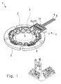
Fig. 1 is a perspective view of a resolver (first embodiment); -
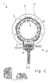
Fig. 2 is a plan view of the resolver (first embodiment); -
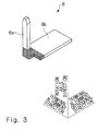
Fig. 3 is a perspective view of a winding terminal (first embodiment); -
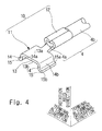
Fig. 4 is a perspective view of a cable terminal attached to an end of an external cable (first embodiment); -
Fig. 5 is an enlarged view of a portion "A" shown inFig. 2 (first embodiment); -
Fig. 6 is a sectional view taken along the line VI-VI ofFig. 5 (first embodiment); -
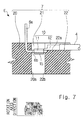
Fig. 7 is a sectional view taken along the line VII-VII ofFig. 6 , in which the illustration of a temporary holding beam which appears on the front side is omitted (first embodiment); -
Fig. 8 is a diagram which corresponds toFig. 6 and shows a state in which the cable terminal is opposed to the winding terminal (first embodiment); -
Fig. 9 is a diagram which corresponds toFig. 6 and shows a state in which the cable terminal is elastically deformed (first embodiment); -
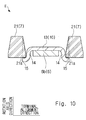
Fig. 10 is a diagram which corresponds toFig. 6 and shows a state in which the cable terminal is temporarily held by a housing (first embodiment); -
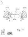
Fig. 11 is a diagram corresponding toFig. 6 (second embodiment); -
Fig. 12 is a diagram corresponding toFig. 6 (third embodiment); -
Fig. 13 is a diagram corresponding toFig. 6 (fourth embodiment); -
Fig. 14 is a diagram corresponding toFig. 6 (fifth embodiment); -
Fig. 15 is a diagram corresponding toFig. 6 (sixth embodiment); and -
Fig. 16 is a diagram corresponding toFig. 10 ofPatent Literature 1. - A first embodiment of the present invention will be described below with reference to
Figs. 1 to 10 . - As shown in
Figs. 1 and2 , aresolver 1 serving as an angle detection device includes aresolver rotor 2 indicated by an alternate long and two short dashes line, a ring-shaped resolver stator 3, and a plurality ofexternal cables 4. Theresolver rotor 2 is formed as a part of an output shaft of a motor (not shown). Theresolver stator 3 is fixed to the body of the motor and the like. Theresolver stator 3 is connected with the plurality ofexternal cables 4. In this structure, when theresolver rotator 2 rotates relative to theresolver stator 3, a rotation signal corresponding to the rotation is generated in theresolver stator 3 and is output to the outside through theexternal cables 4. - The
resolver stator 3 includes aresolver stator body 5, a plurality of resolver windings (not shown), a plurality of winding terminals 6 (first terminal), a terminal holding base 7 (a housing, a terminal holding portion), and aninsulating cover 8. - The
resolver stator body 5 is a stacked structure made of a magnetic material and is formed in a ring shape. Theresolver stator body 5 includes a plurality ofmagnetic pole portions 9 which project toward the inner peripheral side. - The plurality of resolver windings are respectively wound around the plurality of
magnetic pole portions 9 of theresolver stator body 5. - The plurality of
winding terminals 6 are intermediate members which connect the plurality of resolver windings to the plurality ofexternal cables 4, respectively. Eachwinding terminal 6 includes awinding portion 6a around which the corresponding resolver winding is wound. The windingportion 6a projects in a direction parallel to the rotation axis of theresolver rotor 2. - The
terminal holding base 7 is a portion that supports the plurality ofwinding terminals 6. Theterminal holding base 7 is formed on the periphery of theresolver stator body 5. - The
insulating cover 8 is a cover that electrically insulates theresolver stator body 5 from the plurality of resolver windings. In this embodiment, theterminal holding base 7 and theinsulating cover 8 are integrally formed. - The terms "rotation axis direction (first direction)", "terminal alignment direction (second direction)", and "terminal alignment orthogonal direction (third direction)" will now be defined. The rotation axis direction is a direction parallel to the rotation axis of the
resolver rotor 2 as shown inFigs. 1 and2 . In the rotation axis direction, a direction in which the windingportion 6a of each winding terminal 6 projects is defined as a rotation axis projecting direction, and a direction opposite to the rotation axis projecting direction is defined as a rotation axis anti-projecting direction. The terminal alignment direction is a direction in which the plurality of windingterminals 6 are arranged. The terminal alignment direction is orthogonal to the rotation axis direction. The terminal alignment orthogonal direction is a direction orthogonal to each of the rotation axis direction and the terminal alignment direction. - Each cable terminal 10 (second terminal) is attached to an end of the corresponding
external cable 4. Eachcable terminal 10 is spot-welded to the corresponding windingterminal 6 in a state where eachcable terminal 10 is temporarily held by theterminal holding base 7, thereby electrically connecting the resolver windings to theexternal cables 4, respectively. - In this embodiment, a terminal temporary holding structure E includes at least the winding
terminals 6, theterminal holding base 7, and thecable terminals 10. - Next, the terminal temporary holding structure E will be described in detail.
- As shown in
Fig. 3 , each windingterminal 6 includes the windingportion 6a and a winding-side spot-weldedportion 6b (first welded portion). The windingportion 6a is a portion around which the corresponding resolver winding is wound. The windingportion 6a is formed to be elongated in the rotation axis direction. The winding-side spot-weldedportion 6b is a portion where the windingterminal 6 and thecable terminal 10 are spot-welded. The winding-side spot-weldedportion 6b is formed in a flat plate shape orthogonal to the rotation axis direction. The winding-side spot-weldedportion 6b has a rectangular shape. The longitudinal direction of the winding-side spot-weldedportion 6b is parallel to the terminal alignment orthogonal direction. The windingportion 6a and the winding-side spot-weldedportion 6b are integrally formed so as to be orthogonal to each other. Referring toFig. 3 , the hatched area of the windingterminal 6 indicates a portion to be embedded in theterminal holding base 7. The windingterminal 6 is partially embedded in theterminal holding base 7, so that the windingterminal 6 is held by the terminal holding base 7 (also seeFig. 7 ). - As shown in
Fig. 4 , eachexternal cable 4 includes acentral conductor 4a and anexternal coating 4b. Eachcable terminal 10 is attached to an end of the correspondingexternal cable 4. Eachcable terminal 10 includes acable terminal body 11 and anopen barrel 12. Thecable terminal body 11 and theopen barrel 12 are integrally formed by plate bending. Theopen barrel 12 is a portion that is attached to thecentral conductor 4a of the correspondingexternal cable 4 by crimping. Thecable terminal body 11 includes a cable-side spot-welded portion 13 (second welded portion), a pair of elastic connectingportions 14, and a pair of temporary heldportions 15. The cable-side spot-weldedportion 13 is a portion where the windingterminal 6 and thecable terminal 10 are spot-welded. The cable-side spot-weldedportion 13 is formed in a flat plate shape orthogonal to the rotation axis direction. The cable-side spot-weldedportion 13 has anupper surface 13a that faces in the rotation axis projecting direction, and alower surface 13b that faces in the rotation axis anti-projecting direction. The pair of elastic connectingportions 14 is formed in a flat plate shape and projects in the rotation axis anti-projecting direction from both ends of the cable-side spot-weldedportion 13 on the terminal alignment direction side. The pair of elastic connectingportions 14 is orthogonal to the terminal alignment direction. Each elastic connectingportion 14 has aninner surface 14a that faces inward, and anouter surface 14b that faces outward. The pair of elastic connectingportions 14 is disposed so as to sandwich the cable-side spot-weldedportion 13 in the terminal alignment direction. Each of the pair of temporary heldportions 15 is formed in a flat plate shape and projects from an end of a corresponding one of the pair of elastic connectingportions 14 on the rotation axis anti-projecting direction side in such a manner that the temporary heldportions 15 are separated from each other. The pair of temporary heldportions 15 is orthogonal to the rotation axis direction. Each temporary heldportion 15 has anupper surface 15a that faces in the rotation axis projecting direction, and alower surface 15b that faces in the rotation axis anti-projecting direction. The pair of temporary heldportions 15 is disposed so as to sandwich the cable-side spot-weldedportion 13 in the terminal alignment direction. The presence of the pair of elastic connectingportions 14 facilitates the elastic displacement of the pair of temporary heldportions 15 so that they can approach each other. - As shown in
Figs. 5 to 7 , theterminal holding base 7 includes a windingterminal holding portion 20 in which the windingterminals 6 are embedded, a plurality of temporary holding beams 21 that temporarily hold the plurality ofcable terminals 10, and abarrel supporting portion 22 that supports theopen barrel 12 of eachcable terminal 10. As shown inFig. 7 , the windingterminal holding portion 20, thetemporary holding beam 21, and thebarrel supporting portion 22 are arranged in this order in the terminal alignment orthogonal direction. Note that inFig. 5 , the illustration of somecable terminals 10 is omitted for convenience of explanation. - The winding
terminal holding portion 20 is a portion in which the windingportions 6a and the winding-side spot-weldedportions 6b of the windingterminals 6 are partially embedded to thereby support the windingterminals 6. The windingterminal holding portion 20 has a winding-side opposedsurface 20a that is opposed to thebarrel supporting portion 22. - As shown in
Fig. 7 , eachtemporary holding beam 21 is a beam-like portion extending toward thebarrel supporting portion 22 from the winding-side opposedsurface 20a of the windingterminal holding portion 20. The plurality of temporary holding beams 21 are formed at predetermined intervals in the terminal alignment direction. As shown inFig. 6 , eachtemporary holding beam 21 is formed with a thickness that gradually increases in the rotation axis anti-projecting direction. In other words, eachtemporary holding beam 21 is formed to have a substantially trapezoidal shape in cross-section. Specifically, eachtemporary holding beam 21 includes a pair oftemporary holding portions 21a indicated by an alternate long and two short dashes line. Eachtemporary holding portion 21a is opposed to the corresponding temporary heldportion 15 of thecable terminal 10 in the rotation axis direction. Eachtemporary holding portion 21 a is located on the rotation axis projecting direction side of the temporary heldportion 15 of eachcable terminal 10. Each of the pair oftemporary holding portions 21 a has aninclined guide surface 21b which is inclined in such a manner that the pair oftemporary holding portions 21 opposed to each other in the terminal alignment direction approaches each other in the rotation axis anti-projecting direction. - As shown in
Fig. 7 , thebarrel supporting portion 22 has abarrel supporting surface 22a and a cable-sideopposed surface 22b. Thebarrel supporting surface 22a is a surface that is opposed to theopen barrel 12 of thecable terminal 10 in the rotation axis direction and supports theopen barrel 12. The cable-sideopposed surface 22b is a surface that is opposed to the winding-side opposedsurface 20a of the windingterminal holding portion 20. - Next, a method for assembling the
resolver 1 will be described. Referring first toFig. 4 , eachcable terminal 10 is attached to an end of the correspondingexternal cable 4 by using a crimp tool. Referring next toFig. 8 , thecable terminal 10 is caused to descend in the direction indicated by an arrow X in a state where the cable-side spot-weldedportion 13 of thecable terminal 10 is opposed to the winding-side spot-weldedportion 6b of the windingterminal 6. Then each of the pair of temporary heldportions 15 is brought into contact with a corresponding one of the inclined guide surfaces 21 b of the pair oftemporary holding portions 21 a opposed to each other in the terminal alignment direction. When thecable terminal 10 is caused to descend continuously in the direction indicated by the arrow X, the pair of temporary heldportions 15 is elastically displaced so as to approach each other due to a reaction from eachinclined guide surface 21b as shown inFig. 9 . Further, thecable terminal 10 is caused to descend continuously in the direction indicated by the arrow X. Then, when the pair of temporary heldportions 15 has passed over thetemporary holding portions 21a as shown inFig. 10 , the pair of temporary heldportions 15 is elastically displaced in such a manner that the temporary heldportions 15 are separated from each other, and the cable-side spot-weldedportion 13 is seated on the winding-side spot-weldedportion 6b of the windingterminal 6, so that the cable-side spot-weldedportion 13 and the winding-side spot-weldedportion 6b of the windingterminal 6 are opposed to each other in the rotation axis direction. The cable-side spot-weldedportion 13 is located on the rotation axis projecting direction side of the winding-side spot-weldedportion 6b of the windingterminal 6. In the state where thecable terminal 10 is temporarily held by theterminal holding base 7 and the windingterminal 6, the cable-side spot-weldedportion 13 of thecable terminal 10 is located on the rotation axis projecting direction side relative to the winding-side spot-weldedportion 6b of the windingterminal 6, and the temporary heldportions 15 of thecable terminal 10 are located on the rotation axis anti-projecting direction side relative to thetemporary holding portions 21a of the temporary holding beams 21. Accordingly, thecable terminal 10 is sandwiched between theterminal holding base 7 and the windingterminal 6 in the rotation axis direction. - At this time, if an external force acts on the
external cable 4, for example, and an external force acts on the cable-side spot-weldedportion 13 in the rotation axis projecting direction, the pair of temporary heldportions 15 is hooked on the pair oftemporary holding portions 21 a, which inhibits thecable terminal 10 from further ascending in the rotation axis projecting direction. At this time, if an external force acts on theexternal cable 4, for example, and an external force acts on the cable-side spot-weldedportion 13 in the rotation axis anti-projecting direction, the cable-side spot-weldedportion 13 abuts against the winding-side spot-weldedportion 6b of the windingterminal 6, which inhibits thecable terminal 10 from further descending in the rotation axis anti-projecting direction. - At this time, if an external force acts on the
external cable 4, for example, and an external force acts on the cable-side spot-weldedportion 13 in the terminal alignment orthogonal direction, the pair of temporary heldportions 15 is brought into contact with the winding-side opposedsurface 20a or the cable-sideopposed surface 22b as shown inFig. 7 , which inhibits thecable terminal 10 from further moving in the terminal alignment orthogonal direction. - At this time, if an external force acts on the
external cable 4, for example, and an external force acts on the cable-side spot-weldedportion 13 in the terminal alignment direction, the pair of elastic connectingportions 14 is brought into contact with the pair oftemporary holding portions 21a as shown inFig. 10 , which inhibits thecable terminal 10 from further moving in the terminal alignment direction. - Lastly, in the state shown in
Fig. 10 , the cable-side spot-weldedportion 13 and the winding-side spot-weldedportion 6b of the windingterminal 6 are spot-welded by using a spot welding machine. - The first embodiment of the present invention described above has the following features.
-
- (1) The terminal temporary holding structure E includes: the winding terminals 6 (first terminal) each including the winding-side spot-welded
portion 6b (first welded portion) having a flat plate shape; the terminal holding base 7 (housing) that holds the windingterminals 6; and the cable terminals 10 (second terminal) that are respectively connected with theexternal cables 4 and include the cable-side spot-welded portion 13 (second welded portion) having a flat plate shape. As shown inFig. 10 , eachcable terminal 10 is temporarily held by theterminal holding base 7 in such a manner that the winding-side spot-weldedportion 6b and the cable-side spot-weldedportion 13 are opposed to each other, so as to weld the cable-side spot-weldedportion 13 of eachcable terminal 10 to the winding-side spot-weldedportion 6b of each windingterminal 6. Eachcable terminal 10 is temporarily held by theterminal holding base 7 at at least two locations that sandwich the cable-side spot-weldedportion 13. The above structure makes it possible to maintain the position of eachcable terminal 10 temporarily held by theterminal holding base 7, even when an external force acts on theexternal cables 4. - (2) As shown in
Fig. 10 , thecable terminal 10 is sandwiched between the windingterminal 6 and theterminal holding base 7 in a direction orthogonal to the winding-side spot-weldedportion 6b of the windingterminal 6. According to the above structure, temporal holding by thetemporal holder 7 is achieved with a simple structure.
Alternatively, thecable terminal 10 may be press-fitted between the pair of temporary holding beams 21 opposed to each other. Also in this case, the position of thecable terminal 10 temporarily held by theterminal holding base 7 can be stabilized. - (3) The
cable terminal 10 further includes the pair of temporary heldportions 15 disposed so as to sandwich the cable-side spot-weldedportion 13. Theterminal holding base 7 includes the pair oftemporary holding portions 21 a that is opposed to the pair of temporary heldportions 15 of thecable terminal 10 in the direction orthogonal to the winding-side spot-weldedportion 6b of the windingterminal 6. According to the above structure, thecable terminal 10 is caused to pass between the pair oftemporary holding portions 21a by utilizing the elastic displacement of thecable terminal 10, thereby making it possible to sandwich thecable terminal 10 between the windingterminal 6 and theterminal holding base 7. - (4) Further, each of the pair of elastic connecting
portions 14 extending in the rotation axis direction (direction different from a direction parallel to the cable-side spot-welded portion 13) is formed between the cable-side spot-weldedportion 13 and a corresponding one of the pair of temporary heldportions 15. The above structure facilitates the elastic displacement of the pair of temporary heldportions 15 of eachcable terminal 10, thereby facilitating work for sandwiching thecable terminal 10 between the windingterminal 6 and theterminal holding base 7. - (5) As shown in
Fig. 10 , the windingterminal 6 is located between the pair of elastic connectingportions 14 in the state where thecable terminal 10 is temporarily held by theterminal holding base 7. The above structure suppresses relative movements of the windingterminal 6 and thecable terminal 10 in the terminal alignment direction (in a direction in which the pair of elastic connectingportions 14 faces each other). - (7) As shown in
Fig. 9 , each of the pair oftemporary holding portions 21 a has theinclined guide surface 21 b which is inclined in such a manner that the pair oftemporary holding portions 21a approaches each other in the direction from thecable terminal 10 to the windingterminal 6. In other words, thetemporary holding portions 21a respectively have the inclined guide surfaces 21b which are inclined so as to approach each other in the rotation axis anti-projecting direction. According to the above structure, the pair of temporary heldportions 15 is elastically displaced so as to approach each other, simply by pressing thecable terminal 10 in the rotation axis anti-projecting direction. This facilitates work for sandwiching thecable terminal 10 between the windingterminal 6 and theterminal holding base 7. - (8) The
resolver 1 includes at least the terminal temporary holding structure E and theexternal cables 4 which are respectively connected to thecable terminals 10. - Next, a second embodiment of the present invention will be described with reference to
Fig. 11 . Here, differences between this embodiment and the first embodiment will be mainly described, while a repeat of previous descriptions is omitted. Components of this embodiment corresponding to the components of the first embodiment described above are denoted by the same reference numerals as those of the first embodiment as a rule. - As shown in
Fig. 11 , the dimension of the pair of elastic connectingportions 14 in the rotation axis direction is set to be greater than that of the first embodiment, thereby further facilitating the elastic displacement of the pair of temporary heldportions 15 in the direction in which the temporary heldportions 15 approach each other. - Next, a third embodiment of the present invention will be described with reference to
Fig. 12 . Here, differences between this embodiment and the first embodiment will be mainly described, while a repeat of previous descriptions is omitted. Components of this embodiment corresponding to the components of the first embodiment described above are denoted by the same reference numerals as those of the first embodiment as a rule. - As shown in
Fig. 12 , the pair oftemporary holding portions 21a sandwiching the winding-side spot-weldedportion 6b of the windingterminal 6 in the terminal alignment direction may be formed so as to be elastically displaceable in a direction in which thetemporary holding portions 21 a are separated from each other. In the example shown inFig. 12 , the formation ofrecesses 21c, which are opened in the rotation axis anti-projecting direction, in the respective temporary holding beams 21 allows the pair oftemporary holding portions 21a sandwiching the winding-side spot-weldedportion 6b of the windingterminal 6 in the terminal alignment direction to be elastically displaced in the direction in which thetemporary holding portions 21 a are separated from each other. According to the above structure, the pair of temporary heldportions 15 can more easily pass over the pair oftemporary holding portions 21a, which facilitates work for sandwiching thecable terminal 10 between the windingterminal 6 and theterminal holding base 7. Note that it is preferable to form a slit (not shown) in eachtemporary holding portion 21a so as to facilitate the elastic displacement of the pair oftemporary holding portions 21 a in the direction in which thetemporary holding portions 21a sandwiching the winding-side spot-weldedportion 6b of the windingterminal 6 in the terminal alignment direction are separated from each other. - Next, a fourth embodiment of the present invention will be described with reference to
Fig. 13 . Here, differences between this embodiment and the first embodiment will be mainly described, while a repeat of previous descriptions is omitted. Components of this embodiment corresponding to the components of the first embodiment described above are denoted by the same reference numerals as those of the first embodiment as a rule. - As shown in
Fig. 13 , the pair of elastic connectingportions 14 and the pair of temporary heldportions 15 of eachcable terminal 10 can be omitted. In this case, it is preferable that eachtemporary holding beam 21 be provided with amovement regulating portion 21d that is opposed to the cable-side spot-weldedportion 13 in the terminal alignment direction. Themovement regulating portion 21d can prevent the cable-side spot-weldedportion 13, which is temporarily held by theterminal holding base 7, from moving in the terminal alignment direction. - Next, a fifth embodiment of the present invention will be described with reference to
Fig. 14 . Here, differences between this embodiment and the fourth embodiment will be mainly described, while a repeat of previous descriptions is omitted. Components of this embodiment corresponding to the components of the fourth embodiment described above are denoted by the same reference numerals as those of the fourth embodiment as a rule. - As shown in
Fig. 14 , also in the structure of the fourth embodiment described above, the pair oftemporary holding portions 21a sandwiching the winding-side spot-weldedportion 6b of the windingterminal 6 in the terminal alignment direction may be formed so as to be elastically displaceable in the direction in which thetemporary holding portions 21a are separated from each other. According to the above structure, the cable-side spot-weldedportion 13 can more easily pass over the pair oftemporary holding portions 21 a, which facilitates work for sandwiching thecable terminal 10 between the windingterminal 6 and theterminal holding base 7. Note that it is preferable to form a slit (not shown) in eachtemporary holding portion 21a so as to facilitate the elastic displacement of the pair oftemporary holding portions 21a in the direction in which thetemporary holding portions 21 a sandwiching the winding-side spot-weldedportion 6b of the windingterminal 6 in the terminal alignment direction are separated from each other. - Next, a sixth embodiment of the present invention will be described with reference to
Fig. 15 . Here, differences between this embodiment and the fifth embodiment will be mainly described, while a repeat of previous descriptions is omitted. Components of this embodiment corresponding to the components of the fifth embodiment described above are denoted by the same reference numerals as those of the fifth embodiment as a rule. - As shown in
Fig. 15 , instead of forming themovement regulating portion 21d of the fifth embodiment, a pair ofcurved portions 6c, which curves in the rotation axis projecting direction, may be formed at both ends of the winding-side spot-weldedportion 6b of the windingterminal 6 in the terminal alignment direction. The above structure can also prevent the cable-side spot-weldedportion 13, which is temporarily held by theterminal holding base 7, from moving in the terminal alignment direction. - Lastly, referring to
Figs. 10 to 15 , when thecable terminal 10 is sandwiched between the winding-side spot-weldedportion 6b of the windingterminal 6 and thetemporary holding portions 21a of the temporary holding beams 21 in the rotation axis direction, thecable terminal 10 is seemingly restrained from moving in the rotation axis direction. However, in practice, for convenience of manufacturing tolerance, thecable terminal 10 is temporarily held so as to be slightly movable in the rotation axis direction, while thecable terminal 10 is sandwiched between the winding-side spot-weldedportion 6b of the windingterminal 6 and thetemporary holding portions 21a of the temporary holding beams 21 in the rotation axis direction. - This application is based upon and claims the benefit of priority from Japanese patent application No.
2012-154733, filed on July 10, 2012 -
- 1
- RESOLVER
- 2
- RESOLVER ROTOR
- 3
- RESOLVER STATOR
- 4
- EXTERNAL CABLE
- 4a
- CENTRAL CONDUCTOR
- 4b
- EXTERNAL COATING
- 5
- RESOLVER STATOR BODY
- 6
- WINDING TERMINAL (FIRST TERMINAL)
- 6a
- WINDING PORTION
- 6b
- WINDING-SIDE SPOT-WELDED PORTION (FIRST WELDED PORTION)
- 6c
- CURVED PORTION
- 7
- TERMINAL HOLDING BASE (HOUSING)
- 8
- INSULATING COVER
- 9
- MAGNETIC POLE PORTION
- 10
- CABLE TERMINAL (SECOND TERMINAL)
- 11
- CABLE TERMINAL BODY
- 12
- OPEN BARREL
- 13
- CABLE-SIDE SPOT-WELDED PORTION (SECOND WELDED PORTION)
- 13a
- UPPER SURFACE
- 13b
- LOWER SURFACE
- 14
- ELASTIC CONNECTING PORTION
- 14a
- INNER SURFACE
- 14b
- OUTER SURFACE
- 15
- TEMPORARY HELD PORTION
- 15a
- UPPER SURFACE
- 15b
- LOWER SURFACE
- 20
- WINDING TERMINAL HOLDING PORTION
- 20a
- WINDING-SIDE OPPOSED SURFACE
- 21
- TEMPORARY HOLDING BEAM
- 22
- BARREL SUPPORTING PORTION
- 21a
- TEMPORARY HOLDING PORTION
- 21b
- INCLINED GUIDE SURFACE
- 21c
- RECESS
- 21d
- MOVEMENT REGULATING PORTION
- 22a
- BARREL SUPPORTING SURFACE
- 22b
- CABLE-SIDE OPPOSED SURFACE
- E
- TERMINAL TEMPORARY HOLDING STRUCTURE
- X
- ARROW
Claims (8)
- A terminal temporary holding structure comprising:a first terminal including a first welded portion having a flat plate shape;a housing that holds the first terminal; anda second terminal that is connected with an external cable and includes a second welded portion having a flat plate shape, the second terminal being temporarily held by the housing in such a manner that the first welded portion and the second welded portion are opposed to each other, so as to weld the second welded portion of the second terminal to the first welded portion of the first terminal,wherein the second terminal is temporarily held by the housing at at least two locations that sandwich the second welded portion.
- The terminal temporary holding structure according to Claim 1, wherein the second terminal is sandwiched between the first terminal and the housing in a direction orthogonal to the first welded portion of the first terminal.
- The terminal temporary holding structure according to Claim 2, wherein
the second terminal further includes a pair of temporary held portions disposed so as to sandwich the second welded portion, and
the housing includes a pair of temporary holding portions opposed to the pair of temporary held portions of the second terminal in the direction orthogonal to the first welded portion of the first terminal. - The terminal temporary holding structure according to Claim 3, wherein a pair of elastic connecting portions extending in a direction different from a direction parallel to the second welded portion is each formed between the second welded portion and a corresponding one of the pair of temporary held portions.
- The terminal temporary holding structure according to Claim 4, wherein the first terminal is located between the pair of elastic connecting portions in a state where the second terminal is temporarily held by the housing.
- The terminal temporary holding structure according to any one of Claims 3 to 5, wherein the pair of temporary holding portions is formed so as to be elastically displaceable in a direction in which the temporary holding portions are separated from each other.
- The terminal temporary holding structure according to any one of Claims 3 to 6, wherein the pair of temporary holding portions has an inclined guide surface formed thereon, the inclined guide surface being inclined in such a manner that the pair of temporary holding portions approaches each other in a direction from the second terminal to the first terminal.
- A resolver comprising:the terminal temporary holding structure according to any one of Claims 1 to 7; andthe external cable connected to the second terminal.
Applications Claiming Priority (2)
| Application Number | Priority Date | Filing Date | Title |
|---|---|---|---|
| JP2012154733A JP5282158B1 (en) | 2012-07-10 | 2012-07-10 | Terminal temporary holding structure and resolver provided with terminal temporary holding structure |
| PCT/JP2013/002041 WO2014010149A1 (en) | 2012-07-10 | 2013-03-26 | Provisional terminal holding structure, and resolver comprising provisional terminal holding structure |
Publications (3)
| Publication Number | Publication Date |
|---|---|
| EP2874283A1 true EP2874283A1 (en) | 2015-05-20 |
| EP2874283A4 EP2874283A4 (en) | 2016-05-18 |
| EP2874283B1 EP2874283B1 (en) | 2019-02-20 |
Family
ID=49273981
Family Applications (1)
| Application Number | Title | Priority Date | Filing Date |
|---|---|---|---|
| EP13816393.6A Not-in-force EP2874283B1 (en) | 2012-07-10 | 2013-03-26 | Provisional terminal holding structure, and resolver comprising provisional terminal holding structure |
Country Status (4)
| Country | Link |
|---|---|
| US (1) | US9595769B2 (en) |
| EP (1) | EP2874283B1 (en) |
| JP (1) | JP5282158B1 (en) |
| WO (1) | WO2014010149A1 (en) |
Cited By (1)
| Publication number | Priority date | Publication date | Assignee | Title |
|---|---|---|---|---|
| CN109980882A (en) * | 2016-02-09 | 2019-07-05 | 日本航空电子工业株式会社 | Rotary transformer stator |
Families Citing this family (1)
| Publication number | Priority date | Publication date | Assignee | Title |
|---|---|---|---|---|
| MX375808B (en) * | 2015-08-27 | 2025-03-07 | Nissan Motor | METHOD FOR MANUFACTURING TERMINAL MEMBER, METHOD FOR CONNECTING TERMINAL MEMBER AND CONDUCTOR MEMBER, TERMINAL MEMBER, AND WIRING MEMBER. |
Family Cites Families (10)
| Publication number | Priority date | Publication date | Assignee | Title |
|---|---|---|---|---|
| JPS61156455A (en) | 1984-12-28 | 1986-07-16 | Toshiba Corp | Bus branch extending system |
| JPS61156455U (en) * | 1985-03-19 | 1986-09-27 | ||
| JPH11136900A (en) * | 1997-10-28 | 1999-05-21 | Meidensha Corp | Terminal box structure of electrical equipment |
| JP3378194B2 (en) * | 1998-05-12 | 2003-02-17 | 矢崎総業株式会社 | Connector for flat cable |
| JP2004153891A (en) * | 2002-10-29 | 2004-05-27 | Mitsubishi Electric Corp | Rotating electric machine |
| JP4201343B2 (en) | 2005-12-27 | 2008-12-24 | 日本航空電子工業株式会社 | connector |
| JP5092412B2 (en) * | 2007-01-12 | 2012-12-05 | 日本電産株式会社 | Resolver and method for producing resolver |
| JP4972593B2 (en) | 2008-03-24 | 2012-07-11 | 株式会社ミツバ | Electric motor and method for manufacturing electric motor |
| JP2011254676A (en) * | 2010-06-04 | 2011-12-15 | Mitsuba Corp | Motor device |
| JP2012110188A (en) * | 2010-11-19 | 2012-06-07 | Nippon Densan Corp | Intermediate connection member, stator, and motor |
-
2012
- 2012-07-10 JP JP2012154733A patent/JP5282158B1/en not_active Expired - Fee Related
-
2013
- 2013-03-26 US US14/412,345 patent/US9595769B2/en not_active Expired - Fee Related
- 2013-03-26 WO PCT/JP2013/002041 patent/WO2014010149A1/en not_active Ceased
- 2013-03-26 EP EP13816393.6A patent/EP2874283B1/en not_active Not-in-force
Cited By (1)
| Publication number | Priority date | Publication date | Assignee | Title |
|---|---|---|---|---|
| CN109980882A (en) * | 2016-02-09 | 2019-07-05 | 日本航空电子工业株式会社 | Rotary transformer stator |
Also Published As
| Publication number | Publication date |
|---|---|
| EP2874283A4 (en) | 2016-05-18 |
| JP5282158B1 (en) | 2013-09-04 |
| WO2014010149A1 (en) | 2014-01-16 |
| US20150188241A1 (en) | 2015-07-02 |
| JP2014018000A (en) | 2014-01-30 |
| EP2874283B1 (en) | 2019-02-20 |
| US9595769B2 (en) | 2017-03-14 |
Similar Documents
| Publication | Publication Date | Title |
|---|---|---|
| US20040119350A1 (en) | Resolver I/O terminal structure and method of connecting resolver thereby | |
| US11411453B2 (en) | Motor | |
| US10185115B2 (en) | Insert molded lens driving apparatus | |
| US10634517B2 (en) | Resolver stator | |
| KR20180023002A (en) | motor | |
| CN104541437A (en) | Stator unit and motor | |
| WO2018084237A1 (en) | A busbar unit for an electric motor | |
| JP6344362B2 (en) | Storage module and battery connection module | |
| WO2012108514A1 (en) | Bus bar module | |
| US9797749B2 (en) | Resolver | |
| US11336145B2 (en) | Motor | |
| CN111756146A (en) | Stator for motor | |
| JP6581378B2 (en) | Electric motor | |
| EP3145063B1 (en) | Electric motor | |
| US11438680B2 (en) | Transducer for converting between electrical energy and mechanical energy | |
| EP2874283B1 (en) | Provisional terminal holding structure, and resolver comprising provisional terminal holding structure | |
| CN112425041A (en) | Electric machine having a connection unit and method for producing an electric machine having a connection unit | |
| JP5943881B2 (en) | Resolver cable connection structure, manufacturing method thereof, and resolver | |
| JPWO2017170296A1 (en) | Motor and motor manufacturing method | |
| JP2017174685A (en) | Method for manufacturing wire harness, and wire harness | |
| CN211266649U (en) | Electric motor | |
| WO2016152134A1 (en) | Cable connection structure and manufacturing method therefor | |
| CN109301947B (en) | Stator and motor having the same | |
| JP2019030046A (en) | motor | |
| JP2017127103A (en) | Electric motor stator |
Legal Events
| Date | Code | Title | Description |
|---|---|---|---|
| PUAI | Public reference made under article 153(3) epc to a published international application that has entered the european phase |
Free format text: ORIGINAL CODE: 0009012 |
|
| 17P | Request for examination filed |
Effective date: 20150109 |
|
| AK | Designated contracting states |
Kind code of ref document: A1 Designated state(s): AL AT BE BG CH CY CZ DE DK EE ES FI FR GB GR HR HU IE IS IT LI LT LU LV MC MK MT NL NO PL PT RO RS SE SI SK SM TR |
|
| AX | Request for extension of the european patent |
Extension state: BA ME |
|
| DAX | Request for extension of the european patent (deleted) | ||
| RA4 | Supplementary search report drawn up and despatched (corrected) |
Effective date: 20160415 |
|
| RIC1 | Information provided on ipc code assigned before grant |
Ipc: H02K 5/22 20060101AFI20160411BHEP |
|
| STAA | Information on the status of an ep patent application or granted ep patent |
Free format text: STATUS: EXAMINATION IS IN PROGRESS |
|
| 17Q | First examination report despatched |
Effective date: 20170221 |
|
| GRAP | Despatch of communication of intention to grant a patent |
Free format text: ORIGINAL CODE: EPIDOSNIGR1 |
|
| STAA | Information on the status of an ep patent application or granted ep patent |
Free format text: STATUS: GRANT OF PATENT IS INTENDED |
|
| INTG | Intention to grant announced |
Effective date: 20180531 |
|
| GRAJ | Information related to disapproval of communication of intention to grant by the applicant or resumption of examination proceedings by the epo deleted |
Free format text: ORIGINAL CODE: EPIDOSDIGR1 |
|
| STAA | Information on the status of an ep patent application or granted ep patent |
Free format text: STATUS: EXAMINATION IS IN PROGRESS |
|
| GRAP | Despatch of communication of intention to grant a patent |
Free format text: ORIGINAL CODE: EPIDOSNIGR1 |
|
| STAA | Information on the status of an ep patent application or granted ep patent |
Free format text: STATUS: GRANT OF PATENT IS INTENDED |
|
| INTC | Intention to grant announced (deleted) | ||
| INTG | Intention to grant announced |
Effective date: 20180831 |
|
| GRAS | Grant fee paid |
Free format text: ORIGINAL CODE: EPIDOSNIGR3 |
|
| GRAA | (expected) grant |
Free format text: ORIGINAL CODE: 0009210 |
|
| STAA | Information on the status of an ep patent application or granted ep patent |
Free format text: STATUS: THE PATENT HAS BEEN GRANTED |
|
| AK | Designated contracting states |
Kind code of ref document: B1 Designated state(s): AL AT BE BG CH CY CZ DE DK EE ES FI FR GB GR HR HU IE IS IT LI LT LU LV MC MK MT NL NO PL PT RO RS SE SI SK SM TR |
|
| REG | Reference to a national code |
Ref country code: GB Ref legal event code: FG4D |
|
| REG | Reference to a national code |
Ref country code: CH Ref legal event code: EP |
|
| REG | Reference to a national code |
Ref country code: DE Ref legal event code: R096 Ref document number: 602013051110 Country of ref document: DE |
|
| REG | Reference to a national code |
Ref country code: AT Ref legal event code: REF Ref document number: 1099464 Country of ref document: AT Kind code of ref document: T Effective date: 20190315 |
|
| REG | Reference to a national code |
Ref country code: IE Ref legal event code: FG4D |
|
| REG | Reference to a national code |
Ref country code: NL Ref legal event code: MP Effective date: 20190220 |
|
| REG | Reference to a national code |
Ref country code: LT Ref legal event code: MG4D |
|
| PG25 | Lapsed in a contracting state [announced via postgrant information from national office to epo] |
Ref country code: LT Free format text: LAPSE BECAUSE OF FAILURE TO SUBMIT A TRANSLATION OF THE DESCRIPTION OR TO PAY THE FEE WITHIN THE PRESCRIBED TIME-LIMIT Effective date: 20190220 Ref country code: NL Free format text: LAPSE BECAUSE OF FAILURE TO SUBMIT A TRANSLATION OF THE DESCRIPTION OR TO PAY THE FEE WITHIN THE PRESCRIBED TIME-LIMIT Effective date: 20190220 Ref country code: SE Free format text: LAPSE BECAUSE OF FAILURE TO SUBMIT A TRANSLATION OF THE DESCRIPTION OR TO PAY THE FEE WITHIN THE PRESCRIBED TIME-LIMIT Effective date: 20190220 Ref country code: PT Free format text: LAPSE BECAUSE OF FAILURE TO SUBMIT A TRANSLATION OF THE DESCRIPTION OR TO PAY THE FEE WITHIN THE PRESCRIBED TIME-LIMIT Effective date: 20190620 Ref country code: NO Free format text: LAPSE BECAUSE OF FAILURE TO SUBMIT A TRANSLATION OF THE DESCRIPTION OR TO PAY THE FEE WITHIN THE PRESCRIBED TIME-LIMIT Effective date: 20190520 Ref country code: FI Free format text: LAPSE BECAUSE OF FAILURE TO SUBMIT A TRANSLATION OF THE DESCRIPTION OR TO PAY THE FEE WITHIN THE PRESCRIBED TIME-LIMIT Effective date: 20190220 |
|
| PG25 | Lapsed in a contracting state [announced via postgrant information from national office to epo] |
Ref country code: HR Free format text: LAPSE BECAUSE OF FAILURE TO SUBMIT A TRANSLATION OF THE DESCRIPTION OR TO PAY THE FEE WITHIN THE PRESCRIBED TIME-LIMIT Effective date: 20190220 Ref country code: RS Free format text: LAPSE BECAUSE OF FAILURE TO SUBMIT A TRANSLATION OF THE DESCRIPTION OR TO PAY THE FEE WITHIN THE PRESCRIBED TIME-LIMIT Effective date: 20190220 Ref country code: LV Free format text: LAPSE BECAUSE OF FAILURE TO SUBMIT A TRANSLATION OF THE DESCRIPTION OR TO PAY THE FEE WITHIN THE PRESCRIBED TIME-LIMIT Effective date: 20190220 Ref country code: GR Free format text: LAPSE BECAUSE OF FAILURE TO SUBMIT A TRANSLATION OF THE DESCRIPTION OR TO PAY THE FEE WITHIN THE PRESCRIBED TIME-LIMIT Effective date: 20190521 Ref country code: BG Free format text: LAPSE BECAUSE OF FAILURE TO SUBMIT A TRANSLATION OF THE DESCRIPTION OR TO PAY THE FEE WITHIN THE PRESCRIBED TIME-LIMIT Effective date: 20190520 Ref country code: IS Free format text: LAPSE BECAUSE OF FAILURE TO SUBMIT A TRANSLATION OF THE DESCRIPTION OR TO PAY THE FEE WITHIN THE PRESCRIBED TIME-LIMIT Effective date: 20190620 |
|
| REG | Reference to a national code |
Ref country code: AT Ref legal event code: MK05 Ref document number: 1099464 Country of ref document: AT Kind code of ref document: T Effective date: 20190220 |
|
| PG25 | Lapsed in a contracting state [announced via postgrant information from national office to epo] |
Ref country code: SK Free format text: LAPSE BECAUSE OF FAILURE TO SUBMIT A TRANSLATION OF THE DESCRIPTION OR TO PAY THE FEE WITHIN THE PRESCRIBED TIME-LIMIT Effective date: 20190220 Ref country code: AL Free format text: LAPSE BECAUSE OF FAILURE TO SUBMIT A TRANSLATION OF THE DESCRIPTION OR TO PAY THE FEE WITHIN THE PRESCRIBED TIME-LIMIT Effective date: 20190220 Ref country code: ES Free format text: LAPSE BECAUSE OF FAILURE TO SUBMIT A TRANSLATION OF THE DESCRIPTION OR TO PAY THE FEE WITHIN THE PRESCRIBED TIME-LIMIT Effective date: 20190220 Ref country code: CZ Free format text: LAPSE BECAUSE OF FAILURE TO SUBMIT A TRANSLATION OF THE DESCRIPTION OR TO PAY THE FEE WITHIN THE PRESCRIBED TIME-LIMIT Effective date: 20190220 Ref country code: RO Free format text: LAPSE BECAUSE OF FAILURE TO SUBMIT A TRANSLATION OF THE DESCRIPTION OR TO PAY THE FEE WITHIN THE PRESCRIBED TIME-LIMIT Effective date: 20190220 Ref country code: IT Free format text: LAPSE BECAUSE OF FAILURE TO SUBMIT A TRANSLATION OF THE DESCRIPTION OR TO PAY THE FEE WITHIN THE PRESCRIBED TIME-LIMIT Effective date: 20190220 Ref country code: DK Free format text: LAPSE BECAUSE OF FAILURE TO SUBMIT A TRANSLATION OF THE DESCRIPTION OR TO PAY THE FEE WITHIN THE PRESCRIBED TIME-LIMIT Effective date: 20190220 Ref country code: EE Free format text: LAPSE BECAUSE OF FAILURE TO SUBMIT A TRANSLATION OF THE DESCRIPTION OR TO PAY THE FEE WITHIN THE PRESCRIBED TIME-LIMIT Effective date: 20190220 |
|
| REG | Reference to a national code |
Ref country code: CH Ref legal event code: PL |
|
| REG | Reference to a national code |
Ref country code: DE Ref legal event code: R097 Ref document number: 602013051110 Country of ref document: DE |
|
| PG25 | Lapsed in a contracting state [announced via postgrant information from national office to epo] |
Ref country code: LU Free format text: LAPSE BECAUSE OF NON-PAYMENT OF DUE FEES Effective date: 20190326 Ref country code: SM Free format text: LAPSE BECAUSE OF FAILURE TO SUBMIT A TRANSLATION OF THE DESCRIPTION OR TO PAY THE FEE WITHIN THE PRESCRIBED TIME-LIMIT Effective date: 20190220 Ref country code: PL Free format text: LAPSE BECAUSE OF FAILURE TO SUBMIT A TRANSLATION OF THE DESCRIPTION OR TO PAY THE FEE WITHIN THE PRESCRIBED TIME-LIMIT Effective date: 20190220 |
|
| REG | Reference to a national code |
Ref country code: BE Ref legal event code: MM Effective date: 20190331 |
|
| PLBE | No opposition filed within time limit |
Free format text: ORIGINAL CODE: 0009261 |
|
| STAA | Information on the status of an ep patent application or granted ep patent |
Free format text: STATUS: NO OPPOSITION FILED WITHIN TIME LIMIT |
|
| PG25 | Lapsed in a contracting state [announced via postgrant information from national office to epo] |
Ref country code: AT Free format text: LAPSE BECAUSE OF FAILURE TO SUBMIT A TRANSLATION OF THE DESCRIPTION OR TO PAY THE FEE WITHIN THE PRESCRIBED TIME-LIMIT Effective date: 20190220 Ref country code: MC Free format text: LAPSE BECAUSE OF FAILURE TO SUBMIT A TRANSLATION OF THE DESCRIPTION OR TO PAY THE FEE WITHIN THE PRESCRIBED TIME-LIMIT Effective date: 20190220 |
|
| 26N | No opposition filed |
Effective date: 20191121 |
|
| GBPC | Gb: european patent ceased through non-payment of renewal fee |
Effective date: 20190520 |
|
| PG25 | Lapsed in a contracting state [announced via postgrant information from national office to epo] |
Ref country code: IE Free format text: LAPSE BECAUSE OF NON-PAYMENT OF DUE FEES Effective date: 20190326 Ref country code: CH Free format text: LAPSE BECAUSE OF NON-PAYMENT OF DUE FEES Effective date: 20190331 Ref country code: LI Free format text: LAPSE BECAUSE OF NON-PAYMENT OF DUE FEES Effective date: 20190331 |
|
| PG25 | Lapsed in a contracting state [announced via postgrant information from national office to epo] |
Ref country code: FR Free format text: LAPSE BECAUSE OF NON-PAYMENT OF DUE FEES Effective date: 20190420 Ref country code: BE Free format text: LAPSE BECAUSE OF NON-PAYMENT OF DUE FEES Effective date: 20190331 Ref country code: SI Free format text: LAPSE BECAUSE OF FAILURE TO SUBMIT A TRANSLATION OF THE DESCRIPTION OR TO PAY THE FEE WITHIN THE PRESCRIBED TIME-LIMIT Effective date: 20190220 |
|
| PG25 | Lapsed in a contracting state [announced via postgrant information from national office to epo] |
Ref country code: TR Free format text: LAPSE BECAUSE OF FAILURE TO SUBMIT A TRANSLATION OF THE DESCRIPTION OR TO PAY THE FEE WITHIN THE PRESCRIBED TIME-LIMIT Effective date: 20190220 |
|
| PG25 | Lapsed in a contracting state [announced via postgrant information from national office to epo] |
Ref country code: GB Free format text: LAPSE BECAUSE OF NON-PAYMENT OF DUE FEES Effective date: 20190520 |
|
| PG25 | Lapsed in a contracting state [announced via postgrant information from national office to epo] |
Ref country code: MT Free format text: LAPSE BECAUSE OF NON-PAYMENT OF DUE FEES Effective date: 20190326 |
|
| PG25 | Lapsed in a contracting state [announced via postgrant information from national office to epo] |
Ref country code: CY Free format text: LAPSE BECAUSE OF FAILURE TO SUBMIT A TRANSLATION OF THE DESCRIPTION OR TO PAY THE FEE WITHIN THE PRESCRIBED TIME-LIMIT Effective date: 20190220 |
|
| PG25 | Lapsed in a contracting state [announced via postgrant information from national office to epo] |
Ref country code: HU Free format text: LAPSE BECAUSE OF FAILURE TO SUBMIT A TRANSLATION OF THE DESCRIPTION OR TO PAY THE FEE WITHIN THE PRESCRIBED TIME-LIMIT; INVALID AB INITIO Effective date: 20130326 |
|
| PGFP | Annual fee paid to national office [announced via postgrant information from national office to epo] |
Ref country code: DE Payment date: 20220203 Year of fee payment: 10 |
|
| PG25 | Lapsed in a contracting state [announced via postgrant information from national office to epo] |
Ref country code: MK Free format text: LAPSE BECAUSE OF FAILURE TO SUBMIT A TRANSLATION OF THE DESCRIPTION OR TO PAY THE FEE WITHIN THE PRESCRIBED TIME-LIMIT Effective date: 20190220 |
|
| REG | Reference to a national code |
Ref country code: DE Ref legal event code: R119 Ref document number: 602013051110 Country of ref document: DE |
|
| PG25 | Lapsed in a contracting state [announced via postgrant information from national office to epo] |
Ref country code: DE Free format text: LAPSE BECAUSE OF NON-PAYMENT OF DUE FEES Effective date: 20231003 |