EP2874199A1 - Method for manufacturing prismatic battery case - Google Patents
Method for manufacturing prismatic battery case Download PDFInfo
- Publication number
- EP2874199A1 EP2874199A1 EP20140755576 EP14755576A EP2874199A1 EP 2874199 A1 EP2874199 A1 EP 2874199A1 EP 20140755576 EP20140755576 EP 20140755576 EP 14755576 A EP14755576 A EP 14755576A EP 2874199 A1 EP2874199 A1 EP 2874199A1
- Authority
- EP
- European Patent Office
- Prior art keywords
- main body
- sealing cover
- hollow material
- battery case
- open end
- Prior art date
- Legal status (The legal status is an assumption and is not a legal conclusion. Google has not performed a legal analysis and makes no representation as to the accuracy of the status listed.)
- Ceased
Links
Images




Classifications
-
- H—ELECTRICITY
- H01—ELECTRIC ELEMENTS
- H01M—PROCESSES OR MEANS, e.g. BATTERIES, FOR THE DIRECT CONVERSION OF CHEMICAL ENERGY INTO ELECTRICAL ENERGY
- H01M50/00—Constructional details or processes of manufacture of the non-active parts of electrochemical cells other than fuel cells, e.g. hybrid cells
- H01M50/10—Primary casings; Jackets or wrappings
- H01M50/102—Primary casings; Jackets or wrappings characterised by their shape or physical structure
- H01M50/103—Primary casings; Jackets or wrappings characterised by their shape or physical structure prismatic or rectangular
-
- B—PERFORMING OPERATIONS; TRANSPORTING
- B21—MECHANICAL METAL-WORKING WITHOUT ESSENTIALLY REMOVING MATERIAL; PUNCHING METAL
- B21C—MANUFACTURE OF METAL SHEETS, WIRE, RODS, TUBES, PROFILES OR LIKE SEMI-MANUFACTURED PRODUCTS OTHERWISE THAN BY ROLLING; AUXILIARY OPERATIONS USED IN CONNECTION WITH METAL-WORKING WITHOUT ESSENTIALLY REMOVING MATERIAL
- B21C1/00—Manufacture of metal sheets, wire, rods, tubes or like semi-manufactured products by drawing
- B21C1/003—Drawing materials of special alloys so far as the composition of the alloy requires or permits special drawing methods or sequences
-
- B—PERFORMING OPERATIONS; TRANSPORTING
- B21—MECHANICAL METAL-WORKING WITHOUT ESSENTIALLY REMOVING MATERIAL; PUNCHING METAL
- B21C—MANUFACTURE OF METAL SHEETS, WIRE, RODS, TUBES, PROFILES OR LIKE SEMI-MANUFACTURED PRODUCTS OTHERWISE THAN BY ROLLING; AUXILIARY OPERATIONS USED IN CONNECTION WITH METAL-WORKING WITHOUT ESSENTIALLY REMOVING MATERIAL
- B21C23/00—Extruding metal; Impact extrusion
- B21C23/02—Making uncoated products
- B21C23/04—Making uncoated products by direct extrusion
- B21C23/14—Making other products
-
- B—PERFORMING OPERATIONS; TRANSPORTING
- B29—WORKING OF PLASTICS; WORKING OF SUBSTANCES IN A PLASTIC STATE IN GENERAL
- B29C—SHAPING OR JOINING OF PLASTICS; SHAPING OF MATERIAL IN A PLASTIC STATE, NOT OTHERWISE PROVIDED FOR; AFTER-TREATMENT OF THE SHAPED PRODUCTS, e.g. REPAIRING
- B29C48/00—Extrusion moulding, i.e. expressing the moulding material through a die or nozzle which imparts the desired form; Apparatus therefor
- B29C48/001—Combinations of extrusion moulding with other shaping operations
- B29C48/0018—Combinations of extrusion moulding with other shaping operations combined with shaping by orienting, stretching or shrinking, e.g. film blowing
-
- B—PERFORMING OPERATIONS; TRANSPORTING
- B29—WORKING OF PLASTICS; WORKING OF SUBSTANCES IN A PLASTIC STATE IN GENERAL
- B29C—SHAPING OR JOINING OF PLASTICS; SHAPING OF MATERIAL IN A PLASTIC STATE, NOT OTHERWISE PROVIDED FOR; AFTER-TREATMENT OF THE SHAPED PRODUCTS, e.g. REPAIRING
- B29C48/00—Extrusion moulding, i.e. expressing the moulding material through a die or nozzle which imparts the desired form; Apparatus therefor
- B29C48/001—Combinations of extrusion moulding with other shaping operations
- B29C48/0022—Combinations of extrusion moulding with other shaping operations combined with cutting
-
- B—PERFORMING OPERATIONS; TRANSPORTING
- B29—WORKING OF PLASTICS; WORKING OF SUBSTANCES IN A PLASTIC STATE IN GENERAL
- B29D—PRODUCING PARTICULAR ARTICLES FROM PLASTICS OR FROM SUBSTANCES IN A PLASTIC STATE
- B29D99/00—Subject matter not provided for in other groups of this subclass
- B29D99/006—Producing casings, e.g. accumulator cases
-
- H—ELECTRICITY
- H01—ELECTRIC ELEMENTS
- H01M—PROCESSES OR MEANS, e.g. BATTERIES, FOR THE DIRECT CONVERSION OF CHEMICAL ENERGY INTO ELECTRICAL ENERGY
- H01M10/00—Secondary cells; Manufacture thereof
- H01M10/04—Construction or manufacture in general
-
- H—ELECTRICITY
- H01—ELECTRIC ELEMENTS
- H01M—PROCESSES OR MEANS, e.g. BATTERIES, FOR THE DIRECT CONVERSION OF CHEMICAL ENERGY INTO ELECTRICAL ENERGY
- H01M50/00—Constructional details or processes of manufacture of the non-active parts of electrochemical cells other than fuel cells, e.g. hybrid cells
- H01M50/10—Primary casings; Jackets or wrappings
- H01M50/116—Primary casings; Jackets or wrappings characterised by the material
-
- H—ELECTRICITY
- H01—ELECTRIC ELEMENTS
- H01M—PROCESSES OR MEANS, e.g. BATTERIES, FOR THE DIRECT CONVERSION OF CHEMICAL ENERGY INTO ELECTRICAL ENERGY
- H01M50/00—Constructional details or processes of manufacture of the non-active parts of electrochemical cells other than fuel cells, e.g. hybrid cells
- H01M50/10—Primary casings; Jackets or wrappings
- H01M50/116—Primary casings; Jackets or wrappings characterised by the material
- H01M50/117—Inorganic material
-
- H—ELECTRICITY
- H01—ELECTRIC ELEMENTS
- H01M—PROCESSES OR MEANS, e.g. BATTERIES, FOR THE DIRECT CONVERSION OF CHEMICAL ENERGY INTO ELECTRICAL ENERGY
- H01M50/00—Constructional details or processes of manufacture of the non-active parts of electrochemical cells other than fuel cells, e.g. hybrid cells
- H01M50/10—Primary casings; Jackets or wrappings
- H01M50/116—Primary casings; Jackets or wrappings characterised by the material
- H01M50/117—Inorganic material
- H01M50/119—Metals
-
- H—ELECTRICITY
- H01—ELECTRIC ELEMENTS
- H01M—PROCESSES OR MEANS, e.g. BATTERIES, FOR THE DIRECT CONVERSION OF CHEMICAL ENERGY INTO ELECTRICAL ENERGY
- H01M50/00—Constructional details or processes of manufacture of the non-active parts of electrochemical cells other than fuel cells, e.g. hybrid cells
- H01M50/10—Primary casings; Jackets or wrappings
- H01M50/116—Primary casings; Jackets or wrappings characterised by the material
- H01M50/121—Organic material
-
- H—ELECTRICITY
- H01—ELECTRIC ELEMENTS
- H01M—PROCESSES OR MEANS, e.g. BATTERIES, FOR THE DIRECT CONVERSION OF CHEMICAL ENERGY INTO ELECTRICAL ENERGY
- H01M50/00—Constructional details or processes of manufacture of the non-active parts of electrochemical cells other than fuel cells, e.g. hybrid cells
- H01M50/10—Primary casings; Jackets or wrappings
- H01M50/131—Primary casings; Jackets or wrappings characterised by physical properties, e.g. gas permeability, size or heat resistance
- H01M50/133—Thickness
-
- H—ELECTRICITY
- H01—ELECTRIC ELEMENTS
- H01M—PROCESSES OR MEANS, e.g. BATTERIES, FOR THE DIRECT CONVERSION OF CHEMICAL ENERGY INTO ELECTRICAL ENERGY
- H01M50/00—Constructional details or processes of manufacture of the non-active parts of electrochemical cells other than fuel cells, e.g. hybrid cells
- H01M50/10—Primary casings; Jackets or wrappings
- H01M50/147—Lids or covers
- H01M50/148—Lids or covers characterised by their shape
- H01M50/15—Lids or covers characterised by their shape for prismatic or rectangular cells
-
- H—ELECTRICITY
- H01—ELECTRIC ELEMENTS
- H01M—PROCESSES OR MEANS, e.g. BATTERIES, FOR THE DIRECT CONVERSION OF CHEMICAL ENERGY INTO ELECTRICAL ENERGY
- H01M50/00—Constructional details or processes of manufacture of the non-active parts of electrochemical cells other than fuel cells, e.g. hybrid cells
- H01M50/10—Primary casings; Jackets or wrappings
- H01M50/147—Lids or covers
- H01M50/155—Lids or covers characterised by the material
- H01M50/157—Inorganic material
-
- H—ELECTRICITY
- H01—ELECTRIC ELEMENTS
- H01M—PROCESSES OR MEANS, e.g. BATTERIES, FOR THE DIRECT CONVERSION OF CHEMICAL ENERGY INTO ELECTRICAL ENERGY
- H01M50/00—Constructional details or processes of manufacture of the non-active parts of electrochemical cells other than fuel cells, e.g. hybrid cells
- H01M50/10—Primary casings; Jackets or wrappings
- H01M50/147—Lids or covers
- H01M50/155—Lids or covers characterised by the material
- H01M50/157—Inorganic material
- H01M50/159—Metals
-
- H—ELECTRICITY
- H01—ELECTRIC ELEMENTS
- H01M—PROCESSES OR MEANS, e.g. BATTERIES, FOR THE DIRECT CONVERSION OF CHEMICAL ENERGY INTO ELECTRICAL ENERGY
- H01M50/00—Constructional details or processes of manufacture of the non-active parts of electrochemical cells other than fuel cells, e.g. hybrid cells
- H01M50/10—Primary casings; Jackets or wrappings
- H01M50/147—Lids or covers
- H01M50/155—Lids or covers characterised by the material
- H01M50/16—Organic material
-
- H—ELECTRICITY
- H01—ELECTRIC ELEMENTS
- H01M—PROCESSES OR MEANS, e.g. BATTERIES, FOR THE DIRECT CONVERSION OF CHEMICAL ENERGY INTO ELECTRICAL ENERGY
- H01M50/00—Constructional details or processes of manufacture of the non-active parts of electrochemical cells other than fuel cells, e.g. hybrid cells
- H01M50/10—Primary casings; Jackets or wrappings
- H01M50/147—Lids or covers
- H01M50/166—Lids or covers characterised by the methods of assembling casings with lids
- H01M50/169—Lids or covers characterised by the methods of assembling casings with lids by welding, brazing or soldering
-
- H—ELECTRICITY
- H01—ELECTRIC ELEMENTS
- H01M—PROCESSES OR MEANS, e.g. BATTERIES, FOR THE DIRECT CONVERSION OF CHEMICAL ENERGY INTO ELECTRICAL ENERGY
- H01M50/00—Constructional details or processes of manufacture of the non-active parts of electrochemical cells other than fuel cells, e.g. hybrid cells
- H01M50/10—Primary casings; Jackets or wrappings
- H01M50/183—Sealing members
- H01M50/184—Sealing members characterised by their shape or structure
-
- H—ELECTRICITY
- H01—ELECTRIC ELEMENTS
- H01M—PROCESSES OR MEANS, e.g. BATTERIES, FOR THE DIRECT CONVERSION OF CHEMICAL ENERGY INTO ELECTRICAL ENERGY
- H01M50/00—Constructional details or processes of manufacture of the non-active parts of electrochemical cells other than fuel cells, e.g. hybrid cells
- H01M50/10—Primary casings; Jackets or wrappings
- H01M50/183—Sealing members
- H01M50/186—Sealing members characterised by the disposition of the sealing members
-
- H—ELECTRICITY
- H01—ELECTRIC ELEMENTS
- H01M—PROCESSES OR MEANS, e.g. BATTERIES, FOR THE DIRECT CONVERSION OF CHEMICAL ENERGY INTO ELECTRICAL ENERGY
- H01M50/00—Constructional details or processes of manufacture of the non-active parts of electrochemical cells other than fuel cells, e.g. hybrid cells
- H01M50/10—Primary casings; Jackets or wrappings
- H01M50/183—Sealing members
- H01M50/19—Sealing members characterised by the material
- H01M50/191—Inorganic material
-
- H—ELECTRICITY
- H01—ELECTRIC ELEMENTS
- H01M—PROCESSES OR MEANS, e.g. BATTERIES, FOR THE DIRECT CONVERSION OF CHEMICAL ENERGY INTO ELECTRICAL ENERGY
- H01M50/00—Constructional details or processes of manufacture of the non-active parts of electrochemical cells other than fuel cells, e.g. hybrid cells
- H01M50/10—Primary casings; Jackets or wrappings
- H01M50/183—Sealing members
- H01M50/19—Sealing members characterised by the material
- H01M50/193—Organic material
-
- B—PERFORMING OPERATIONS; TRANSPORTING
- B29—WORKING OF PLASTICS; WORKING OF SUBSTANCES IN A PLASTIC STATE IN GENERAL
- B29C—SHAPING OR JOINING OF PLASTICS; SHAPING OF MATERIAL IN A PLASTIC STATE, NOT OTHERWISE PROVIDED FOR; AFTER-TREATMENT OF THE SHAPED PRODUCTS, e.g. REPAIRING
- B29C71/00—After-treatment of articles without altering their shape; Apparatus therefor
- B29C71/02—Thermal after-treatment
- B29C2071/022—Annealing
-
- B—PERFORMING OPERATIONS; TRANSPORTING
- B29—WORKING OF PLASTICS; WORKING OF SUBSTANCES IN A PLASTIC STATE IN GENERAL
- B29C—SHAPING OR JOINING OF PLASTICS; SHAPING OF MATERIAL IN A PLASTIC STATE, NOT OTHERWISE PROVIDED FOR; AFTER-TREATMENT OF THE SHAPED PRODUCTS, e.g. REPAIRING
- B29C2791/00—Shaping characteristics in general
- B29C2791/001—Shaping in several steps
-
- B—PERFORMING OPERATIONS; TRANSPORTING
- B29—WORKING OF PLASTICS; WORKING OF SUBSTANCES IN A PLASTIC STATE IN GENERAL
- B29C—SHAPING OR JOINING OF PLASTICS; SHAPING OF MATERIAL IN A PLASTIC STATE, NOT OTHERWISE PROVIDED FOR; AFTER-TREATMENT OF THE SHAPED PRODUCTS, e.g. REPAIRING
- B29C2793/00—Shaping techniques involving a cutting or machining operation
- B29C2793/0027—Cutting off
-
- B—PERFORMING OPERATIONS; TRANSPORTING
- B29—WORKING OF PLASTICS; WORKING OF SUBSTANCES IN A PLASTIC STATE IN GENERAL
- B29C—SHAPING OR JOINING OF PLASTICS; SHAPING OF MATERIAL IN A PLASTIC STATE, NOT OTHERWISE PROVIDED FOR; AFTER-TREATMENT OF THE SHAPED PRODUCTS, e.g. REPAIRING
- B29C48/00—Extrusion moulding, i.e. expressing the moulding material through a die or nozzle which imparts the desired form; Apparatus therefor
- B29C48/001—Combinations of extrusion moulding with other shaping operations
-
- B—PERFORMING OPERATIONS; TRANSPORTING
- B29—WORKING OF PLASTICS; WORKING OF SUBSTANCES IN A PLASTIC STATE IN GENERAL
- B29C—SHAPING OR JOINING OF PLASTICS; SHAPING OF MATERIAL IN A PLASTIC STATE, NOT OTHERWISE PROVIDED FOR; AFTER-TREATMENT OF THE SHAPED PRODUCTS, e.g. REPAIRING
- B29C48/00—Extrusion moulding, i.e. expressing the moulding material through a die or nozzle which imparts the desired form; Apparatus therefor
- B29C48/03—Extrusion moulding, i.e. expressing the moulding material through a die or nozzle which imparts the desired form; Apparatus therefor characterised by the shape of the extruded material at extrusion
- B29C48/07—Flat, e.g. panels
-
- B—PERFORMING OPERATIONS; TRANSPORTING
- B29—WORKING OF PLASTICS; WORKING OF SUBSTANCES IN A PLASTIC STATE IN GENERAL
- B29C—SHAPING OR JOINING OF PLASTICS; SHAPING OF MATERIAL IN A PLASTIC STATE, NOT OTHERWISE PROVIDED FOR; AFTER-TREATMENT OF THE SHAPED PRODUCTS, e.g. REPAIRING
- B29C48/00—Extrusion moulding, i.e. expressing the moulding material through a die or nozzle which imparts the desired form; Apparatus therefor
- B29C48/03—Extrusion moulding, i.e. expressing the moulding material through a die or nozzle which imparts the desired form; Apparatus therefor characterised by the shape of the extruded material at extrusion
- B29C48/09—Articles with cross-sections having partially or fully enclosed cavities, e.g. pipes or channels
-
- B—PERFORMING OPERATIONS; TRANSPORTING
- B29—WORKING OF PLASTICS; WORKING OF SUBSTANCES IN A PLASTIC STATE IN GENERAL
- B29C—SHAPING OR JOINING OF PLASTICS; SHAPING OF MATERIAL IN A PLASTIC STATE, NOT OTHERWISE PROVIDED FOR; AFTER-TREATMENT OF THE SHAPED PRODUCTS, e.g. REPAIRING
- B29C55/00—Shaping by stretching, e.g. drawing through a die; Apparatus therefor
- B29C55/30—Drawing through a die
-
- B—PERFORMING OPERATIONS; TRANSPORTING
- B29—WORKING OF PLASTICS; WORKING OF SUBSTANCES IN A PLASTIC STATE IN GENERAL
- B29C—SHAPING OR JOINING OF PLASTICS; SHAPING OF MATERIAL IN A PLASTIC STATE, NOT OTHERWISE PROVIDED FOR; AFTER-TREATMENT OF THE SHAPED PRODUCTS, e.g. REPAIRING
- B29C65/00—Joining or sealing of preformed parts, e.g. welding of plastics materials; Apparatus therefor
- B29C65/02—Joining or sealing of preformed parts, e.g. welding of plastics materials; Apparatus therefor by heating, with or without pressure
- B29C65/14—Joining or sealing of preformed parts, e.g. welding of plastics materials; Apparatus therefor by heating, with or without pressure using wave energy, i.e. electromagnetic radiation, or particle radiation
- B29C65/16—Laser beams
- B29C65/1629—Laser beams characterised by the way of heating the interface
- B29C65/1648—Laser beams characterised by the way of heating the interface radiating the edges of the parts to be joined
-
- B—PERFORMING OPERATIONS; TRANSPORTING
- B29—WORKING OF PLASTICS; WORKING OF SUBSTANCES IN A PLASTIC STATE IN GENERAL
- B29C—SHAPING OR JOINING OF PLASTICS; SHAPING OF MATERIAL IN A PLASTIC STATE, NOT OTHERWISE PROVIDED FOR; AFTER-TREATMENT OF THE SHAPED PRODUCTS, e.g. REPAIRING
- B29C65/00—Joining or sealing of preformed parts, e.g. welding of plastics materials; Apparatus therefor
- B29C65/56—Joining or sealing of preformed parts, e.g. welding of plastics materials; Apparatus therefor using mechanical means or mechanical connections, e.g. form-fits
- B29C65/58—Snap connection
-
- B—PERFORMING OPERATIONS; TRANSPORTING
- B29—WORKING OF PLASTICS; WORKING OF SUBSTANCES IN A PLASTIC STATE IN GENERAL
- B29C—SHAPING OR JOINING OF PLASTICS; SHAPING OF MATERIAL IN A PLASTIC STATE, NOT OTHERWISE PROVIDED FOR; AFTER-TREATMENT OF THE SHAPED PRODUCTS, e.g. REPAIRING
- B29C66/00—General aspects of processes or apparatus for joining preformed parts
- B29C66/01—General aspects dealing with the joint area or with the area to be joined
- B29C66/05—Particular design of joint configurations
- B29C66/10—Particular design of joint configurations particular design of the joint cross-sections
- B29C66/12—Joint cross-sections combining only two joint-segments; Tongue and groove joints; Tenon and mortise joints; Stepped joint cross-sections
- B29C66/122—Joint cross-sections combining only two joint-segments, i.e. one of the parts to be joined comprising only two joint-segments in the joint cross-section
- B29C66/1222—Joint cross-sections combining only two joint-segments, i.e. one of the parts to be joined comprising only two joint-segments in the joint cross-section comprising at least a lapped joint-segment
-
- B—PERFORMING OPERATIONS; TRANSPORTING
- B29—WORKING OF PLASTICS; WORKING OF SUBSTANCES IN A PLASTIC STATE IN GENERAL
- B29C—SHAPING OR JOINING OF PLASTICS; SHAPING OF MATERIAL IN A PLASTIC STATE, NOT OTHERWISE PROVIDED FOR; AFTER-TREATMENT OF THE SHAPED PRODUCTS, e.g. REPAIRING
- B29C66/00—General aspects of processes or apparatus for joining preformed parts
- B29C66/01—General aspects dealing with the joint area or with the area to be joined
- B29C66/05—Particular design of joint configurations
- B29C66/10—Particular design of joint configurations particular design of the joint cross-sections
- B29C66/12—Joint cross-sections combining only two joint-segments; Tongue and groove joints; Tenon and mortise joints; Stepped joint cross-sections
- B29C66/122—Joint cross-sections combining only two joint-segments, i.e. one of the parts to be joined comprising only two joint-segments in the joint cross-section
- B29C66/1224—Joint cross-sections combining only two joint-segments, i.e. one of the parts to be joined comprising only two joint-segments in the joint cross-section comprising at least a butt joint-segment
-
- B—PERFORMING OPERATIONS; TRANSPORTING
- B29—WORKING OF PLASTICS; WORKING OF SUBSTANCES IN A PLASTIC STATE IN GENERAL
- B29C—SHAPING OR JOINING OF PLASTICS; SHAPING OF MATERIAL IN A PLASTIC STATE, NOT OTHERWISE PROVIDED FOR; AFTER-TREATMENT OF THE SHAPED PRODUCTS, e.g. REPAIRING
- B29C66/00—General aspects of processes or apparatus for joining preformed parts
- B29C66/50—General aspects of joining tubular articles; General aspects of joining long products, i.e. bars or profiled elements; General aspects of joining single elements to tubular articles, hollow articles or bars; General aspects of joining several hollow-preforms to form hollow or tubular articles
- B29C66/51—Joining tubular articles, profiled elements or bars; Joining single elements to tubular articles, hollow articles or bars; Joining several hollow-preforms to form hollow or tubular articles
- B29C66/53—Joining single elements to tubular articles, hollow articles or bars
- B29C66/534—Joining single elements to open ends of tubular or hollow articles or to the ends of bars
-
- B—PERFORMING OPERATIONS; TRANSPORTING
- B29—WORKING OF PLASTICS; WORKING OF SUBSTANCES IN A PLASTIC STATE IN GENERAL
- B29C—SHAPING OR JOINING OF PLASTICS; SHAPING OF MATERIAL IN A PLASTIC STATE, NOT OTHERWISE PROVIDED FOR; AFTER-TREATMENT OF THE SHAPED PRODUCTS, e.g. REPAIRING
- B29C66/00—General aspects of processes or apparatus for joining preformed parts
- B29C66/80—General aspects of machine operations or constructions and parts thereof
- B29C66/83—General aspects of machine operations or constructions and parts thereof characterised by the movement of the joining or pressing tools
- B29C66/832—Reciprocating joining or pressing tools
- B29C66/8322—Joining or pressing tools reciprocating along one axis
-
- B—PERFORMING OPERATIONS; TRANSPORTING
- B29—WORKING OF PLASTICS; WORKING OF SUBSTANCES IN A PLASTIC STATE IN GENERAL
- B29C—SHAPING OR JOINING OF PLASTICS; SHAPING OF MATERIAL IN A PLASTIC STATE, NOT OTHERWISE PROVIDED FOR; AFTER-TREATMENT OF THE SHAPED PRODUCTS, e.g. REPAIRING
- B29C71/00—After-treatment of articles without altering their shape; Apparatus therefor
- B29C71/02—Thermal after-treatment
-
- B—PERFORMING OPERATIONS; TRANSPORTING
- B29—WORKING OF PLASTICS; WORKING OF SUBSTANCES IN A PLASTIC STATE IN GENERAL
- B29L—INDEXING SCHEME ASSOCIATED WITH SUBCLASS B29C, RELATING TO PARTICULAR ARTICLES
- B29L2031/00—Other particular articles
- B29L2031/34—Electrical apparatus, e.g. sparking plugs or parts thereof
- B29L2031/3468—Batteries, accumulators or fuel cells
-
- B—PERFORMING OPERATIONS; TRANSPORTING
- B29—WORKING OF PLASTICS; WORKING OF SUBSTANCES IN A PLASTIC STATE IN GENERAL
- B29L—INDEXING SCHEME ASSOCIATED WITH SUBCLASS B29C, RELATING TO PARTICULAR ARTICLES
- B29L2031/00—Other particular articles
- B29L2031/34—Electrical apparatus, e.g. sparking plugs or parts thereof
- B29L2031/3481—Housings or casings incorporating or embedding electric or electronic elements
-
- B—PERFORMING OPERATIONS; TRANSPORTING
- B29—WORKING OF PLASTICS; WORKING OF SUBSTANCES IN A PLASTIC STATE IN GENERAL
- B29L—INDEXING SCHEME ASSOCIATED WITH SUBCLASS B29C, RELATING TO PARTICULAR ARTICLES
- B29L2031/00—Other particular articles
- B29L2031/712—Containers; Packaging elements or accessories, Packages
- B29L2031/7146—Battery-cases
-
- Y—GENERAL TAGGING OF NEW TECHNOLOGICAL DEVELOPMENTS; GENERAL TAGGING OF CROSS-SECTIONAL TECHNOLOGIES SPANNING OVER SEVERAL SECTIONS OF THE IPC; TECHNICAL SUBJECTS COVERED BY FORMER USPC CROSS-REFERENCE ART COLLECTIONS [XRACs] AND DIGESTS
- Y02—TECHNOLOGIES OR APPLICATIONS FOR MITIGATION OR ADAPTATION AGAINST CLIMATE CHANGE
- Y02E—REDUCTION OF GREENHOUSE GAS [GHG] EMISSIONS, RELATED TO ENERGY GENERATION, TRANSMISSION OR DISTRIBUTION
- Y02E60/00—Enabling technologies; Technologies with a potential or indirect contribution to GHG emissions mitigation
- Y02E60/10—Energy storage using batteries
-
- Y—GENERAL TAGGING OF NEW TECHNOLOGICAL DEVELOPMENTS; GENERAL TAGGING OF CROSS-SECTIONAL TECHNOLOGIES SPANNING OVER SEVERAL SECTIONS OF THE IPC; TECHNICAL SUBJECTS COVERED BY FORMER USPC CROSS-REFERENCE ART COLLECTIONS [XRACs] AND DIGESTS
- Y02—TECHNOLOGIES OR APPLICATIONS FOR MITIGATION OR ADAPTATION AGAINST CLIMATE CHANGE
- Y02P—CLIMATE CHANGE MITIGATION TECHNOLOGIES IN THE PRODUCTION OR PROCESSING OF GOODS
- Y02P70/00—Climate change mitigation technologies in the production process for final industrial or consumer products
- Y02P70/50—Manufacturing or production processes characterised by the final manufactured product
Definitions
- the present invention relates to a method of manufacturing a prismatic type battery case, and more particularly, to a method of manufacturing a prismatic type battery case in which a main body of the prismatic type battery case is manufactured through an extrusion process and a plurality of drawing processes, so that the main body has a desired thickness, and a crack is prevented from being formed in the main body, thereby decreasing a defect rate.
- lithium secondary batteries having high energy density and discharge voltage are actively researched and widely commercialized.
- Secondary batteries are classified into cylindrical or prismatic type batteries, which include a jelly-roll structure in a cylindrical or prismatic metal can, and pouch type batteries which include a jelly-roll structure in a pouch type case of an aluminum laminate sheet, according to the shapes of battery cases.
- Electrode assemblies accommodated in battery cases are rechargeable generating devices having a stacked structure of a cathode, a separator, and an anode, and are classified into folding type electrode assemblies (jelly-roll structures) which are formed by winding an active material-coated long sheet type cathode and an active material-coated long sheet type anode with a separator therebetween, and stacked type electrode assemblies which are formed by sequentially stacking a plurality of cathodes having a predetermined size and a plurality of anodes having a predetermined size with separators therebetween.
- the jelly-roll structures are easy to manufacture and have high energy density per weight.
- FIG. 1 is an exploded perspective view illustrating a prismatic type battery including the above-described jelly-roll structure.
- FIG. 2 is a vertical cross-sectional view illustrating the battery case of FIG. 1 .
- a prismatic type battery 1 includes a jelly-roll structure 10 accommodated in a prismatic case 20, and a top cap 30 provided with a protruding electrode terminal and coupled to an open upper end of the case 20.
- An anode of the jelly-roll structure 10 is electrically connected through an anode tab 12 to a lower end of an anode terminal 32 disposed on the top cap 30, and the anode terminal 32 is electrically insulated from the top cap 30 by an insulating member 34.
- a cathode tab 14 for the other electrode of the jelly-roll structure 10 is electrically connected to the top cap 30 formed of a conductive material such as aluminum or stainless steel. Thus, the top cap 30 functions as a cathode terminal.
- a sheet type insulating member 40 is inserted between the prismatic case 20 and the jelly-roll structure 10 to electrically insulate the jelly-roll structure 10 and the top cap 30 from each other, except for the anode tab 12 and the cathode tab 14, then, the top cap 30 is installed thereon, and then, a welding process is performed along contact surfaces of the top cap 30 and the prismatic case 20 to couple the top cap 30 and the prismatic case 20 to each other.
- electrolyte is injected through an electrolyte injection hole 43, then, a metal ball (not shown) is welded to the electrolyte injection hole 43 to seal the electrolyte injection hole 43, and then, epoxy is applied to a welded area to complete the prismatic type battery.
- the multi-stage deep drawing method is a manufacturing method using a series of continuous processes from a plate to a final hollow case, so as to have high process efficiency, but has the following limitations. First, since the multi-stage deep drawing method has approximately ten or more complicated and precise processes, manufacturing costs of devices for the processes are significantly high. Secondly, since the types of materials appropriate for a deep drawing process are significantly limited, it is difficult to obtain a battery case having desired material property.
- a prismatic hollow main body is manufactured through a extrusion shaping process, then, a sealing member tightly contacting a lower end of the prismatic hollow main body is manufactured through a forging, blanking, or cutting process, and then, the prismatic hollow main body and the sealing member are welded to each other, thereby manufacturing a prismatic type hollow battery case having a sealed lower end.
- a minimal thickness of the prismatic hollow main body manufactured in the extrusion shaping process is limited to a range from 0.7 to 0.8 mm.
- existing battery cases are required to have a thickness ranging from about 0.3 to 0.5 mm.
- the extrusion shaping process fails to meet the thickness of the existing battery cases.
- Korean Patent Registration No. 1182643 relates to a technology of manufacturing a battery case through an extrusion shaping process and a drawing shaping process, in which: a raw material is shaped into a hollow extruded material through the extrusion shaping process; the hollow extruded material is shaped into a battery case main body having a required thickness through the drawing shaping process; a separate sealing member is manufactured; and the battery case main body and the separate sealing member are adhered to each other, thereby manufacturing the battery case.
- the hollow extruded material has the required thickness through a single drawing process, the shape of the hollow extruded material is severely changed, so as to increase a defect rate, such as a crack of the battery case main body.
- Patent Document 1 Korean Patent Registration No. 1182643
- the present invention aims at providing a method of manufacturing a prismatic type battery case in which a main body of the prismatic type battery case is manufactured through an extrusion process and a plurality of drawing processes, so that the main body has a desired thickness, and a crack is prevented from being formed therein, thereby decreasing a defect rate.
- a method of manufacturing a prismatic type battery case including: extruding a raw material into a prismatic hollow material having both open ends (Step (a)); drawing the hollow material a plurality of times so as to have a desired thickness (Step (b)); manufacturing a main body by cutting the drawn hollow material to a predetermined length (Step (c)); forming a sealing cover having a shape corresponding to an open end of the main body (Step (d)); and adhering the sealing cover to the open end of the main body (Step (e)).
- Step (e) may be performed through laser welding.
- a change in thickness of the hollow material in each of drawing processes may range from 15% to 25%.
- the method may further include performing a heat treatment on the drawn hollow material after each of drawing processes in Step (b) (Step (b')).
- Step (b') may not be performed after the final drawing process of the drawing processes.
- the heat treatment on the drawn hollow material in Step (b') may be performed through annealing.
- the method may further include: forming a leakage prevention recess in the open end of the main body after Step (c) (Step (c')); and forming a protruding part and a leakage prevention protrusion after Step (d) (Step (d')), wherein the protruding part is introduced from the sealing cover into the open end of the main body, and the leakage prevention protrusion is formed on a side surface of the protruding part.
- the method may further include inserting the leakage prevention protrusion into the leakage prevention recess by introducing the protruding part of the sealing cover into the main body before Step (e) (Step (e')).
- the method may further include forming an adhesion recess in the open end of the main body after Step (c) (Step (c")), wherein the sealing cover is inserted into the adhesion recess of the main body and is then adhered to the open end of the main body in Step (e).
- the main body and the sealing cover may be formed of any one selected from aluminum (Al), copper (Cu), iron (Fe), stainless steel (SUS), a ceramic, a polymer, and an equivalent thereof.
- a prismatic type battery case may be manufactured using the steps according to the present invention.
- a main body of a prismatic type battery case is manufactured through an extrusion process and a plurality of drawing processes, so that the main body has a desired thickness, and a crack is prevented from being formed therein, thereby decreasing a defect rate.
- a heat treatment is performed on a hollow material after each drawing process, so as to decrease the hardness and strength of the hollow material and improve formability thereof, thereby preventing a defect from occurring in a subsequent drawing process.
- a leakage prevention recess and a leakage prevention protrusion are formed on a main body and a sealing cover, thereby preventing electrolyte from leaking out of a battery case.
- a method of manufacturing a prismatic type battery case includes: a step of individually manufacturing a main body that is hollow and has a prismatic shape with both open ends, and a sealing cover having a shape corresponding to an open end of the main body; and a step of coupling and adhering the main body and the sealing cover to each other.
- the term "prismatic" is used herein in order to comprehensively express that a cross section of a case includes a straight part, instead of a curved part such as a circular or oval shape.
- the cross section may have a triangular shape, a tetragonal shape, a pentagonal shape, or a rectangular shape with a pair of sides (long sides) longer than the other corresponding pair of sides (short sides).
- the cross section may have a round corner part where two straight parts meet each other.
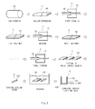
- FIG. 3 is a flowchart illustrating a method of manufacturing a prismatic type battery case according to an embodiment of the present invention.
- a method of manufacturing a prismatic type battery case includes a step (a) of extruding a raw material 50 into a prismatic hollow material 60 having both open ends, a step (b) of drawing the hollow material 60 a plurality of times so as to have a desired thickness, a step (c) of manufacturing a main body 100 by cutting the drawn hollow material 60 to a predetermined length, a step (d) of forming a sealing cover 200 having a shape corresponding to an open end of the main body 100, and a step (e) of adhering the sealing cover 200 to the open end of the main body 100.
- the raw material 50 is shaped into the hollow material 60 through an extrusion process.
- the raw material 50 is pressed against a mold having a cavity corresponding to the shape of the hollow material 60 and is extruded.
- the raw material 50 may be formed of any one selected from aluminum (Al), copper (Cu), iron (Fe), stainless steel (SUS), a ceramic, a polymer, and an equivalent thereof, which are appropriate for the extrusion process, but the present invention is not limited thereto.
- An extruding device performing the step (a) is a commonly used well-known device in the related art, and thus, a detailed description thereof will be omitted.
- the extruded hollow material 60 is drawn a plurality of times.
- a typical drawing process is used to pass a raw material through dies having a smaller cross-sectional area than that of the raw material and draw the raw material, thereby obtaining a product having the same cross-section as that of the dies.
- step (b) dies 70 are prepared and the hollow material 60 is passed between the dies 70, and thus, the thickness of the hollow material 60 is decreased.
- the thickness of the hollow material 60 reaches the desired thickness by performing the drawing process a plurality of times. Since the thickness of the hollow material 60 should be decreased as a plurality of drawing processes are performed, respective sets of dies 70, 71, and 72 of the drawing processes are gradually decreased in inner dimension.
- the thickness of the hollow material 60 reaches the desired thickness by drawing the hollow material 60 a plurality of times in the step (b), a variation in the thickness of the hollow material 60 is not large in one drawing process. Since the thickness of the hollow material 60 reaches the desired thickness through a single drawing process in the related art, the shape of the hollow material 60 is significantly changed to frequently form a crack therein, which increases a defect rate. However, according to the present invention, the thickness of the hollow material 60 reaches the desired thickness through the drawing processes, not through a single drawing process. Thus, a change in the shape of the hollow material 60 is not significant in one drawing process, so as to prevent a crack from being formed therein.
- a change in the thickness of the hollow material 60 in each drawing process of the step (b) is limited within a range from 15% to 25%. If the change in the thickness of the hollow material 60 in one drawing process exceeds 25%, the possibility that a crack is formed in the hollow material 60 increases according to the change. Thus, the change in the thickness of the hollow material 60 in each drawing process may be 25% or less. If the change in the thickness of the hollow material 60 in one drawing process is smaller than 15%, a crack is not formed in the hollow material 60. However, a plurality of additional drawing processes are required, which increases die manufacturing costs, thereby increasing the total manufacturing cost. Thus, the change in the thickness of the hollow material 60 in each drawing process may range from 15% to 25%.
- the present invention further includes a step (b') of performing a heat treatment on the hollow material 60 after each drawing process of the step (b).
- Typical heat treatments improve characteristics of a material by performing heating and cooling processes at appropriate speed and include quenching, tempering, and annealing.
- the annealing appropriately heats a metal material to remove effect caused by a process and thermal history remaining in an inner structure of the metal material, and is a heat treatment method in which a material such as a metal is heated to a predetermined temperature and is slowly cooled to correct inner deformation of the material.
- the annealing decreases the hardness and strength of a material and improves formability thereof to obtain a predetermined structure.
- the heat treatment of the step (b') may be the annealing.
- the heat treatment is performed by annealing the hollow material 60 in the step (b') after each drawing process, so as to improve formability thereof, thereby improving drawing formability in a subsequent drawing process.
- the heat treatment of the step (b') may not be performed after the final drawing process of the drawing processes of the step (b). Accordingly, mechanical property of the hollow material 60 obtained through the final drawing process is ensured.
- step (c) the hollow material 60 drawn through the drawing processes is cut.
- the hollow material 60 is cut to the predetermined length by a separate cutting device (not shown).
- the predetermined length corresponds to the length of a desired product and may be changed according to the types of products. That is, the hollow material 60 having the desired thickness through the drawing processes is cut to the predetermined length by the cutting device, so as to manufacture the main body 100.
- the cutting device for cutting the hollow material 60 is commonly used and well known in the related art, and thus, a detailed description thereof will be omitted.
- the sealing cover 200 is formed.
- a press process is performed on the raw material 50 into the sealing cover 200 having the shape corresponding to the open end of the main body 100.
- the sealing cover 200 may be manufactured through the press process, but the present invention is not limited thereto.
- the sealing cover 200 may be manufactured through one of various processes such as a cutting process and a forging process.
- the main body 100 and the sealing cover 200, manufactured as described above, are washed with a wash liquid. Then, the step (e) of adhering the sealing cover 200 to the open end of the main body 100 is performed.
- the sealing cover 200 is brought into contact with the open end of the main body 100 and is then irradiated with a laser beam 310 from a laser welder 300, whereby contact surfaces of the main body 100 and the sealing cover 200 are welded to each other.
- the shape of an adhesion surface, where the main body 100 and the sealing cover 200 are adhered to each other, may be variously changed.
- a step (c') of forming a leakage prevention recess 110 in the main body 100 is provided after the step (c).
- the leakage prevention recess 110 is formed inside of the open end of the main body 100 by using a method such as a cutting process.
- a step (d') of forming a protruding part 210 and a leakage prevention protrusion 220 on the sealing cover 200 is further provided.
- the protruding part 210 has a shape corresponding to an inner hollow of the main body 100, and the leakage prevention protrusion 220 protrudes into a shape corresponding to the leakage prevention recess 110 in the lateral direction of the protruding part 210.
- the protruding part 210 and the leakage prevention protrusion 220 may be formed through a cutting process or a forging process, but the present invention is not limited thereto.
- a step (e') of introducing the protruding part 210 of the sealing cover 200 into a hollow part of the main body 100 is performed before the step (e).
- the leakage prevention protrusion 220 is inserted in and coupled to the leakage prevention recess 110 of the main body 100 by introducing the protruding part 210 into the hollow part of the main body 100 as described above (refer to FIG. 4B ).
- the step (e) of adhering the main body 100 and the sealing cover 200 to each other by emitting the laser beam 310 between the main body 100 and the sealing cover 200 from the laser welder 300 is performed.
- the adhesion surface of the main body 100 and the sealing cover 200 When the main body 100 and the sealing cover 200 are adhered to each other as described above, the adhesion surface of the main body 100 and the sealing cover 200, provided by the leakage prevention recess 110 and the leakage prevention protrusion 220, has a shape bent a plurality of times. That is, even when a welding defect occurs, since the adhesion surface of the main body 100 and the sealing cover 200 has the bent shape, electrolyte is maximally prevented from leaking out of the main body 100.
- a step (c") of forming an adhesion recess 110' in a main body 100' is provided after the step (c).
- the adhesion recess 110' is formed by cutting an open end of the main body 100' from the outside of the main body 100' to the inside thereof, and has a portion that is open to the outside of the main body 100'. As described above, the adhesion recess 110' is formed through the cutting, but the present invention is not limited thereto.
- a sealing cover 200' is formed into a shape corresponding to the adhesion recess 110' in the step (d).
- the sealing cover 200' formed into the shape corresponding to the adhesion recess 110' of the main body 100' is inserted into the adhesion recess 110' .
- the step (e) of adhering the main body 100' and the sealing cover 200' to each other by emitting a laser beam 310' between the main body 100' and the sealing cover 200' from a laser welder 300' is performed.
- the main bodies 100 and 100' of the prismatic type battery case are manufactured through the extrusion process and the drawing processes, so that the main bodies 100 and 100' have the desired thickness, and a crack is prevented from being formed therein, thereby decreasing a defect rate.
- the heat treatment is performed on the hollow material 60 after each drawing process, so as to decrease the hardness and strength of the hollow material 60 and improve formability thereof, thereby preventing a defect from occurring in a subsequent drawing process.
- the leakage prevention recess and the leakage prevention protrusion are formed on the main body 100 and the sealing cover 200, thereby preventing electrolyte from leaking out of the battery case.
Landscapes
- Chemical & Material Sciences (AREA)
- Electrochemistry (AREA)
- General Chemical & Material Sciences (AREA)
- Chemical Kinetics & Catalysis (AREA)
- Engineering & Computer Science (AREA)
- Inorganic Chemistry (AREA)
- Mechanical Engineering (AREA)
- Manufacturing & Machinery (AREA)
- Sealing Battery Cases Or Jackets (AREA)
- Physics & Mathematics (AREA)
- Thermal Sciences (AREA)
- Optics & Photonics (AREA)
- Health & Medical Sciences (AREA)
- Electromagnetism (AREA)
- Toxicology (AREA)
Abstract
Description
- The present invention relates to a method of manufacturing a prismatic type battery case, and more particularly, to a method of manufacturing a prismatic type battery case in which a main body of the prismatic type battery case is manufactured through an extrusion process and a plurality of drawing processes, so that the main body has a desired thickness, and a crack is prevented from being formed in the main body, thereby decreasing a defect rate.
- As mobile devices are technically developed and are in increasing demand, demands for a secondary battery as an energy source quickly increase. In particular, lithium secondary batteries having high energy density and discharge voltage are actively researched and widely commercialized.
- Secondary batteries are classified into cylindrical or prismatic type batteries, which include a jelly-roll structure in a cylindrical or prismatic metal can, and pouch type batteries which include a jelly-roll structure in a pouch type case of an aluminum laminate sheet, according to the shapes of battery cases.
- Electrode assemblies accommodated in battery cases are rechargeable generating devices having a stacked structure of a cathode, a separator, and an anode, and are classified into folding type electrode assemblies (jelly-roll structures) which are formed by winding an active material-coated long sheet type cathode and an active material-coated long sheet type anode with a separator therebetween, and stacked type electrode assemblies which are formed by sequentially stacking a plurality of cathodes having a predetermined size and a plurality of anodes having a predetermined size with separators therebetween. Of these, the jelly-roll structures are easy to manufacture and have high energy density per weight.
-
FIG. 1 is an exploded perspective view illustrating a prismatic type battery including the above-described jelly-roll structure.FIG. 2 is a vertical cross-sectional view illustrating the battery case ofFIG. 1 . - Referring to
FIG. 1 , aprismatic type battery 1 includes a jelly-roll structure 10 accommodated in aprismatic case 20, and atop cap 30 provided with a protruding electrode terminal and coupled to an open upper end of thecase 20. - An anode of the jelly-
roll structure 10 is electrically connected through ananode tab 12 to a lower end of ananode terminal 32 disposed on thetop cap 30, and theanode terminal 32 is electrically insulated from thetop cap 30 by aninsulating member 34. Acathode tab 14 for the other electrode of the jelly-roll structure 10 is electrically connected to thetop cap 30 formed of a conductive material such as aluminum or stainless steel. Thus, thetop cap 30 functions as a cathode terminal. - A sheet
type insulating member 40 is inserted between theprismatic case 20 and the jelly-roll structure 10 to electrically insulate the jelly-roll structure 10 and thetop cap 30 from each other, except for theanode tab 12 and thecathode tab 14, then, thetop cap 30 is installed thereon, and then, a welding process is performed along contact surfaces of thetop cap 30 and theprismatic case 20 to couple thetop cap 30 and theprismatic case 20 to each other. After that, electrolyte is injected through anelectrolyte injection hole 43, then, a metal ball (not shown) is welded to theelectrolyte injection hole 43 to seal theelectrolyte injection hole 43, and then, epoxy is applied to a welded area to complete the prismatic type battery. - In general, a secondary battery case configured as described above is manufactured using a multi-stage deep drawing method, and side walls of the
prismatic case 20 have the same thickness (A = A') as illustrated inFIG. 2 . The multi-stage deep drawing method is a manufacturing method using a series of continuous processes from a plate to a final hollow case, so as to have high process efficiency, but has the following limitations. First, since the multi-stage deep drawing method has approximately ten or more complicated and precise processes, manufacturing costs of devices for the processes are significantly high. Secondly, since the types of materials appropriate for a deep drawing process are significantly limited, it is difficult to obtain a battery case having desired material property. - To address the limitations in manufacturing a prismatic type battery case according to the multi-stage deep drawing method, a prismatic hollow main body is manufactured through a extrusion shaping process, then, a sealing member tightly contacting a lower end of the prismatic hollow main body is manufactured through a forging, blanking, or cutting process, and then, the prismatic hollow main body and the sealing member are welded to each other, thereby manufacturing a prismatic type hollow battery case having a sealed lower end.
- However, a minimal thickness of the prismatic hollow main body manufactured in the extrusion shaping process is limited to a range from 0.7 to 0.8 mm. However, existing battery cases are required to have a thickness ranging from about 0.3 to 0.5 mm. Thus, the extrusion shaping process fails to meet the thickness of the existing battery cases.
- To address this limitation, Korean Patent Registration No.
1182643 - In this case, since the hollow extruded material has the required thickness through a single drawing process, the shape of the hollow extruded material is severely changed, so as to increase a defect rate, such as a crack of the battery case main body.
- In addition, since the battery case main body and the sealing member are adhered to each other simply through ultrasonic brazing, when a welding defect occurs, electrolyte may leak through a defective area.
- [Patent Document 1] Korean Patent Registration No.
1182643 - Accordingly, the present invention aims at providing a method of manufacturing a prismatic type battery case in which a main body of the prismatic type battery case is manufactured through an extrusion process and a plurality of drawing processes, so that the main body has a desired thickness, and a crack is prevented from being formed therein, thereby decreasing a defect rate.
- According to an aspect of the present invention, there is provided a method of manufacturing a prismatic type battery case, including: extruding a raw material into a prismatic hollow material having both open ends (Step (a)); drawing the hollow material a plurality of times so as to have a desired thickness (Step (b)); manufacturing a main body by cutting the drawn hollow material to a predetermined length (Step (c)); forming a sealing cover having a shape corresponding to an open end of the main body (Step (d)); and adhering the sealing cover to the open end of the main body (Step (e)).
- Step (e) may be performed through laser welding.
- In Step (b), a change in thickness of the hollow material in each of drawing processes may range from 15% to 25%.
- The method may further include performing a heat treatment on the drawn hollow material after each of drawing processes in Step (b) (Step (b')).
- Step (b') may not be performed after the final drawing process of the drawing processes.
- The heat treatment on the drawn hollow material in Step (b') may be performed through annealing.
- The method may further include: forming a leakage prevention recess in the open end of the main body after Step (c) (Step (c')); and forming a protruding part and a leakage prevention protrusion after Step (d) (Step (d')), wherein the protruding part is introduced from the sealing cover into the open end of the main body, and the leakage prevention protrusion is formed on a side surface of the protruding part.
- The method may further include inserting the leakage prevention protrusion into the leakage prevention recess by introducing the protruding part of the sealing cover into the main body before Step (e) (Step (e')).
- The method may further include forming an adhesion recess in the open end of the main body after Step (c) (Step (c")), wherein the sealing cover is inserted into the adhesion recess of the main body and is then adhered to the open end of the main body in Step (e).
- The main body and the sealing cover may be formed of any one selected from aluminum (Al), copper (Cu), iron (Fe), stainless steel (SUS), a ceramic, a polymer, and an equivalent thereof.
- A prismatic type battery case may be manufactured using the steps according to the present invention.
- According to the present invention, the following effects can be attained.
- First, a main body of a prismatic type battery case is manufactured through an extrusion process and a plurality of drawing processes, so that the main body has a desired thickness, and a crack is prevented from being formed therein, thereby decreasing a defect rate.
- Secondly, a heat treatment is performed on a hollow material after each drawing process, so as to decrease the hardness and strength of the hollow material and improve formability thereof, thereby preventing a defect from occurring in a subsequent drawing process.
- Thirdly, a leakage prevention recess and a leakage prevention protrusion are formed on a main body and a sealing cover, thereby preventing electrolyte from leaking out of a battery case.
-
-
FIG. 1 is an exploded perspective view illustrating a prismatic type battery including a jelly-roll structure; -
FIG. 2 is a vertical cross-sectional view illustrating the prismatic type battery case ofFIG. 1 ; -
FIG. 3 is a flowchart illustrating a method of manufacturing a prismatic type battery case according to an embodiment of the present invention; and -
FIGS. 4A to 5B are views illustrating various shapes of a main body and a sealing cover, manufactured using a method of manufacturing a prismatic type battery case, and adhesion states therebetween according to embodiments of the present invention. - Terms used in the following description and scopes of claims are not limited to terms that have been in commonly used dictionaries, and should be interpreted as having a meaning that is consistent with their meaning in the context of the relevant art, so that this disclosure will be thorough and complete, and will fully convey the scope of the inventive concept to those skilled in the art.
- Therefore, the embodiments and drawings proposed herein are just preferable examples for the purpose of illustrations only, not intended to limit the scope of the invention, so it should be understood that other equivalents and modifications could be made thereto without departing from the spirit and scope of the invention. Moreover, detailed descriptions related to well-known functions or configurations will be ruled out in order not to unnecessarily obscure subject matters of the present invention.
- Hereinafter, a method of manufacturing a prismatic type battery case according to preferred embodiments of the present invention will be described with reference to the accompanying drawings.
- A method of manufacturing a prismatic type battery case according to an embodiment of the present invention includes: a step of individually manufacturing a main body that is hollow and has a prismatic shape with both open ends, and a sealing cover having a shape corresponding to an open end of the main body; and a step of coupling and adhering the main body and the sealing cover to each other. The term "prismatic" is used herein in order to comprehensively express that a cross section of a case includes a straight part, instead of a curved part such as a circular or oval shape. For example, the cross section may have a triangular shape, a tetragonal shape, a pentagonal shape, or a rectangular shape with a pair of sides (long sides) longer than the other corresponding pair of sides (short sides). Furthermore, the cross section may have a round corner part where two straight parts meet each other.
-
FIG. 3 is a flowchart illustrating a method of manufacturing a prismatic type battery case according to an embodiment of the present invention. - Referring to
FIG. 3 , a method of manufacturing a prismatic type battery case includes a step (a) of extruding araw material 50 into a prismatichollow material 60 having both open ends, a step (b) of drawing the hollow material 60 a plurality of times so as to have a desired thickness, a step (c) of manufacturing amain body 100 by cutting the drawnhollow material 60 to a predetermined length, a step (d) of forming asealing cover 200 having a shape corresponding to an open end of themain body 100, and a step (e) of adhering thesealing cover 200 to the open end of themain body 100. - In the step (a), the
raw material 50 is shaped into thehollow material 60 through an extrusion process. - To this end, the
raw material 50 is pressed against a mold having a cavity corresponding to the shape of thehollow material 60 and is extruded. Theraw material 50 may be formed of any one selected from aluminum (Al), copper (Cu), iron (Fe), stainless steel (SUS), a ceramic, a polymer, and an equivalent thereof, which are appropriate for the extrusion process, but the present invention is not limited thereto. An extruding device performing the step (a) is a commonly used well-known device in the related art, and thus, a detailed description thereof will be omitted. - In the step (b), the extruded
hollow material 60 is drawn a plurality of times. - A typical drawing process is used to pass a raw material through dies having a smaller cross-sectional area than that of the raw material and draw the raw material, thereby obtaining a product having the same cross-section as that of the dies.
- Also in the step (b), dies 70 are prepared and the
hollow material 60 is passed between the dies 70, and thus, the thickness of thehollow material 60 is decreased. In the step (b), the thickness of thehollow material 60 reaches the desired thickness by performing the drawing process a plurality of times. Since the thickness of thehollow material 60 should be decreased as a plurality of drawing processes are performed, respective sets of dies 70, 71, and 72 of the drawing processes are gradually decreased in inner dimension. - As described above, since the thickness of the
hollow material 60 reaches the desired thickness by drawing the hollow material 60 a plurality of times in the step (b), a variation in the thickness of thehollow material 60 is not large in one drawing process. Since the thickness of thehollow material 60 reaches the desired thickness through a single drawing process in the related art, the shape of thehollow material 60 is significantly changed to frequently form a crack therein, which increases a defect rate. However, according to the present invention, the thickness of thehollow material 60 reaches the desired thickness through the drawing processes, not through a single drawing process. Thus, a change in the shape of thehollow material 60 is not significant in one drawing process, so as to prevent a crack from being formed therein. - A change in the thickness of the
hollow material 60 in each drawing process of the step (b) is limited within a range from 15% to 25%. If the change in the thickness of thehollow material 60 in one drawing process exceeds 25%, the possibility that a crack is formed in thehollow material 60 increases according to the change. Thus, the change in the thickness of thehollow material 60 in each drawing process may be 25% or less. If the change in the thickness of thehollow material 60 in one drawing process is smaller than 15%, a crack is not formed in thehollow material 60. However, a plurality of additional drawing processes are required, which increases die manufacturing costs, thereby increasing the total manufacturing cost. Thus, the change in the thickness of thehollow material 60 in each drawing process may range from 15% to 25%. - The present invention further includes a step (b') of performing a heat treatment on the
hollow material 60 after each drawing process of the step (b). - Typical heat treatments improve characteristics of a material by performing heating and cooling processes at appropriate speed and include quenching, tempering, and annealing.
- The annealing appropriately heats a metal material to remove effect caused by a process and thermal history remaining in an inner structure of the metal material, and is a heat treatment method in which a material such as a metal is heated to a predetermined temperature and is slowly cooled to correct inner deformation of the material. The annealing decreases the hardness and strength of a material and improves formability thereof to obtain a predetermined structure. Thus, the heat treatment of the step (b') may be the annealing.
- That is, the heat treatment is performed by annealing the
hollow material 60 in the step (b') after each drawing process, so as to improve formability thereof, thereby improving drawing formability in a subsequent drawing process. - The heat treatment of the step (b') may not be performed after the final drawing process of the drawing processes of the step (b). Accordingly, mechanical property of the
hollow material 60 obtained through the final drawing process is ensured. - In the step (c), the
hollow material 60 drawn through the drawing processes is cut. - In the step (c), the
hollow material 60 is cut to the predetermined length by a separate cutting device (not shown). The predetermined length corresponds to the length of a desired product and may be changed according to the types of products. That is, thehollow material 60 having the desired thickness through the drawing processes is cut to the predetermined length by the cutting device, so as to manufacture themain body 100. The cutting device for cutting thehollow material 60 is commonly used and well known in the related art, and thus, a detailed description thereof will be omitted. - In the step (d), the sealing
cover 200 is formed. - A press process is performed on the
raw material 50 into the sealingcover 200 having the shape corresponding to the open end of themain body 100. The sealingcover 200 may be manufactured through the press process, but the present invention is not limited thereto. Thus, the sealingcover 200 may be manufactured through one of various processes such as a cutting process and a forging process. - The
main body 100 and the sealingcover 200, manufactured as described above, are washed with a wash liquid. Then, the step (e) of adhering the sealingcover 200 to the open end of themain body 100 is performed. - In the step (e), the sealing
cover 200 is brought into contact with the open end of themain body 100 and is then irradiated with alaser beam 310 from alaser welder 300, whereby contact surfaces of themain body 100 and the sealingcover 200 are welded to each other. The shape of an adhesion surface, where themain body 100 and the sealingcover 200 are adhered to each other, may be variously changed. - Hereinafter, steps of forming the adhesion surface, where the
main body 100 and the sealingcover 200 are adhered to each other, and various shapes of the adhesion surface formed through processes will be described in detail according to exemplary embodiments. - Referring to
FIG. 4A , a step (c') of forming aleakage prevention recess 110 in themain body 100 is provided after the step (c). Theleakage prevention recess 110 is formed inside of the open end of themain body 100 by using a method such as a cutting process. - After the step (d), a step (d') of forming a
protruding part 210 and aleakage prevention protrusion 220 on the sealingcover 200 is further provided. The protrudingpart 210 has a shape corresponding to an inner hollow of themain body 100, and theleakage prevention protrusion 220 protrudes into a shape corresponding to theleakage prevention recess 110 in the lateral direction of theprotruding part 210. The protrudingpart 210 and theleakage prevention protrusion 220 may be formed through a cutting process or a forging process, but the present invention is not limited thereto. - When the
leakage prevention recess 110 is formed in themain body 100, and theprotruding part 210 and theleakage prevention protrusion 220 are formed on the sealingcover 200 as described above, a step (e') of introducing theprotruding part 210 of the sealingcover 200 into a hollow part of themain body 100 is performed before the step (e). Theleakage prevention protrusion 220 is inserted in and coupled to theleakage prevention recess 110 of themain body 100 by introducing theprotruding part 210 into the hollow part of themain body 100 as described above (refer toFIG. 4B ). - After that, as illustrated in
FIG. 4B , the step (e) of adhering themain body 100 and the sealingcover 200 to each other by emitting thelaser beam 310 between themain body 100 and the sealingcover 200 from thelaser welder 300 is performed. - When the
main body 100 and the sealingcover 200 are adhered to each other as described above, the adhesion surface of themain body 100 and the sealingcover 200, provided by theleakage prevention recess 110 and theleakage prevention protrusion 220, has a shape bent a plurality of times. That is, even when a welding defect occurs, since the adhesion surface of themain body 100 and the sealingcover 200 has the bent shape, electrolyte is maximally prevented from leaking out of themain body 100. - Referring to
FIG. 5A , a step (c") of forming an adhesion recess 110' in a main body 100' is provided after the step (c). The adhesion recess 110' is formed by cutting an open end of the main body 100' from the outside of the main body 100' to the inside thereof, and has a portion that is open to the outside of the main body 100'. As described above, the adhesion recess 110' is formed through the cutting, but the present invention is not limited thereto. - When the main body 100' has the adhesion recess 110' in the open end as described above, a sealing cover 200' is formed into a shape corresponding to the adhesion recess 110' in the step (d).
- The sealing cover 200' formed into the shape corresponding to the adhesion recess 110' of the main body 100' is inserted into the adhesion recess 110' . After that, as illustrated in
FIG. 5B , the step (e) of adhering the main body 100' and the sealing cover 200' to each other by emitting a laser beam 310' between the main body 100' and the sealing cover 200' from a laser welder 300' is performed. - In the method of manufacturing the prismatic type battery case according to the present invention, configured as described above, the
main bodies 100 and 100' of the prismatic type battery case are manufactured through the extrusion process and the drawing processes, so that themain bodies 100 and 100' have the desired thickness, and a crack is prevented from being formed therein, thereby decreasing a defect rate. - In addition, the heat treatment is performed on the
hollow material 60 after each drawing process, so as to decrease the hardness and strength of thehollow material 60 and improve formability thereof, thereby preventing a defect from occurring in a subsequent drawing process. - In addition, the leakage prevention recess and the leakage prevention protrusion are formed on the
main body 100 and the sealingcover 200, thereby preventing electrolyte from leaking out of the battery case. - Methods of manufacturing a prismatic type battery case have been described according to the forgoing exemplary embodiments of the present invention.
- The foregoing embodiments should be considered in descriptive sense only and not for purposes of limitation. Therefore, the scope of the invention is defined not by the detailed description of the invention but by the appended claims. In addition, it should be understood that other equivalents and modifications could be made to the appended claims without departing from the spirit or scope of the invention.
Claims (11)
- A method of manufacturing a prismatic type battery case, comprising:extruding a raw material into a prismatic hollow material having both open ends (Step (a));drawing the hollow material a plurality of times so as to have a desired thickness (Step (b));manufacturing a main body by cutting the drawn hollow material to a predetermined length (Step (c));forming a sealing cover having a shape corresponding to an open end of the main body (Step (d)); andadhering the sealing cover to the open end of the main body (Step (e)).
- The method of claim 1, wherein Step (e) is performed through laser welding.
- The method of claim 1, wherein in Step (b), a change in thickness of the hollow material in each of drawing processes ranges from 15% to 25%.
- The method of claim 1, further comprising performing a heat treatment on the drawn hollow material after each of drawing processes in Step (b) (Step (b')).
- The method of claim 4, wherein Step (b') is not performed after the final drawing process of the drawing processes.
- The method of claim 4, wherein the heat treatment on the drawn hollow material in Step (b') is performed through annealing.
- The method of claim 1, further comprising:forming a leakage prevention recess in the open end of the main body after Step (c) (Step (c')); andforming a protruding part and a leakage prevention protrusion after Step (d) (Step (d')), wherein the protruding part is introduced from the sealing cover into the open end of the main body, and the leakage prevention protrusion is formed on a side surface of the protruding part.
- The method of claim 7, further comprising inserting the leakage prevention protrusion into the leakage prevention recess by introducing the protruding part of the sealing cover into the main body before Step (e) (Step (e')).
- The method of claim 1, further comprising forming an adhesion recess in the open end of the main body after Step (c) (Step (c")),
wherein the sealing cover is inserted into the adhesion recess of the main body and is then adhered to the open end of the main body in Step (e). - The method of claim 1, wherein the main body and the sealing cover are formed of any one selected from aluminum (Al), copper (Cu), iron (Fe), stainless steel (SUS), a ceramic, a polymer, and an equivalent thereof.
- A prismatic type battery case manufactured according to the method of any one of claims 1 to 10.
Applications Claiming Priority (2)
| Application Number | Priority Date | Filing Date | Title |
|---|---|---|---|
| KR20130114943A KR20150034946A (en) | 2013-09-27 | 2013-09-27 | Method for production of prismatic battery case |
| PCT/KR2014/003256 WO2015046696A1 (en) | 2013-09-27 | 2014-04-15 | Method for manufacturing prismatic battery case |
Publications (2)
| Publication Number | Publication Date |
|---|---|
| EP2874199A1 true EP2874199A1 (en) | 2015-05-20 |
| EP2874199A4 EP2874199A4 (en) | 2015-09-02 |
Family
ID=52743791
Family Applications (1)
| Application Number | Title | Priority Date | Filing Date |
|---|---|---|---|
| EP14755576.7A Ceased EP2874199A4 (en) | 2013-09-27 | 2014-04-15 | METHOD FOR MANUFACTURING A PRISMATIC BATTERY HOUSING |
Country Status (6)
| Country | Link |
|---|---|
| US (1) | US20150093630A1 (en) |
| EP (1) | EP2874199A4 (en) |
| JP (1) | JP6246822B2 (en) |
| KR (1) | KR20150034946A (en) |
| TW (1) | TWI525875B (en) |
| WO (1) | WO2015046696A1 (en) |
Cited By (2)
| Publication number | Priority date | Publication date | Assignee | Title |
|---|---|---|---|---|
| CN115863729A (en) * | 2021-09-23 | 2023-03-28 | 常州瑞德丰精密技术有限公司 | Power battery shell and production process thereof |
| EP4616970A1 (en) * | 2024-03-11 | 2025-09-17 | Alu Materials Co.,Ltd | Manufacturing apparatus for tubular body of rectangular electric vehicle battery can |
Families Citing this family (12)
| Publication number | Priority date | Publication date | Assignee | Title |
|---|---|---|---|---|
| KR102139065B1 (en) * | 2017-02-13 | 2020-07-29 | 주식회사 엘지화학 | Cylindrical Battery Cell Comprising Inorganic Material Coating Portion |
| KR102328729B1 (en) * | 2018-05-03 | 2021-11-17 | 주식회사 엘지에너지솔루션 | Battery module and battery pack including the same |
| KR102529975B1 (en) * | 2018-06-04 | 2023-05-08 | 에스케이온 주식회사 | Case for secondary battery and battery module having the same |
| KR102179963B1 (en) * | 2019-03-20 | 2020-11-17 | 대주코레스(주) | manufacturing method of battery cell case and battery cell case manufactured by the same |
| US12261282B2 (en) * | 2019-12-05 | 2025-03-25 | Lg Energy Solution, Ltd. | Electrode for secondary battery and method of manufacturing electrode for secondary battery |
| CN111740041A (en) * | 2020-06-28 | 2020-10-02 | 湖北亿纬动力有限公司 | Method for manufacturing battery case, battery case and single cell |
| KR102435376B1 (en) * | 2022-02-10 | 2022-08-23 | (주)티와이 | Secondary battery can manufactured by extrusion method and manufacturing method thereof |
| CN114770592B (en) * | 2022-04-02 | 2023-07-18 | 广东拓斯达科技股份有限公司 | Manufacturing method of high-rigidity drawing arm and drawing arm manufactured by using same |
| KR102571865B1 (en) | 2023-02-02 | 2023-08-29 | (주)알루텍 | stepped portion forming devices and methods for battery can |
| KR20240136162A (en) * | 2023-03-06 | 2024-09-13 | 에스케이온 주식회사 | Method of manufacturing battery module |
| KR102868562B1 (en) * | 2023-04-07 | 2025-10-16 | 주식회사 모리스 | Square battery can, its manufacturing device and manufacturing method |
| KR102916259B1 (en) * | 2024-09-13 | 2026-01-22 | 우종천 | angular battery case manufacturing aluminium-based alloy, angular battery case prepared thereby and method for manufacturing the same |
Family Cites Families (19)
| Publication number | Priority date | Publication date | Assignee | Title |
|---|---|---|---|---|
| DE2738559C3 (en) * | 1977-08-24 | 1982-02-18 | Mannesmann AG, 4000 Düsseldorf | Process for the continuous drawing of tubes |
| JPS58158856A (en) * | 1982-03-16 | 1983-09-21 | Fuji Elelctrochem Co Ltd | Nonaqueous electrolytic battery |
| NZ270808A (en) * | 1994-04-19 | 1998-02-26 | Duracell Inc | Battery housing is a segment of a tubular plastic extrusion |
| JP3610560B2 (en) * | 1995-02-06 | 2005-01-12 | 住友電気工業株式会社 | Waveguide manufacturing method and waveguide |
| JPH09306441A (en) * | 1996-05-17 | 1997-11-28 | Katayama Tokushu Kogyo Kk | Battery can forming material and battery can formed by the material |
| JP2000090893A (en) * | 1998-09-17 | 2000-03-31 | Japan Storage Battery Co Ltd | Battery and method for manufacturing battery |
| JP2001084973A (en) * | 1999-09-17 | 2001-03-30 | Toshiba Corp | Sealed battery and method of manufacturing the same |
| JP2001338624A (en) * | 2000-03-21 | 2001-12-07 | Ngk Insulators Ltd | Anode container for sodium-sulfur cell |
| JP4064642B2 (en) * | 2000-04-28 | 2008-03-19 | 松下電器産業株式会社 | Battery can manufacturing method |
| JP3662838B2 (en) * | 2000-11-20 | 2005-06-22 | 松下電器産業株式会社 | Battery pack manufacturing method |
| JP2005100781A (en) * | 2003-09-24 | 2005-04-14 | Tdk Corp | Organic el element and organic el display |
| JP2005183188A (en) * | 2003-12-19 | 2005-07-07 | Sumiden Asahi Industries Ltd | Battery case and battery case manufacturing method |
| CA2558561A1 (en) * | 2005-09-06 | 2007-03-06 | X-Cyte, Inc. | Battery housing and method of manufacturing the same |
| JP5456967B2 (en) * | 2007-12-06 | 2014-04-02 | 冨士発條株式会社 | Aluminum prismatic battery case |
| KR101128665B1 (en) * | 2008-10-22 | 2012-03-23 | 주식회사 엘지화학 | Secondary Battery Comprising Battery Case of Improved Safety |
| KR101041182B1 (en) * | 2009-10-09 | 2011-06-13 | 김택문 | Aluminum copper busbar manufacturing method and aluminum copper busbar manufactured by this method |
| KR101182643B1 (en) * | 2010-12-01 | 2012-09-14 | (주)아이비티 | Method for Production of Prismatic Battery Case |
| JP5483457B2 (en) * | 2010-12-20 | 2014-05-07 | アイダエンジニアリング株式会社 | Battery, battery container and manufacturing method |
| JP5677130B2 (en) * | 2011-02-22 | 2015-02-25 | 三菱アルミニウム株式会社 | Exterior can for lithium ion secondary battery |
-
2013
- 2013-09-27 KR KR20130114943A patent/KR20150034946A/en not_active Ceased
-
2014
- 2014-04-15 EP EP14755576.7A patent/EP2874199A4/en not_active Ceased
- 2014-04-15 WO PCT/KR2014/003256 patent/WO2015046696A1/en not_active Ceased
- 2014-04-15 JP JP2015539520A patent/JP6246822B2/en active Active
- 2014-07-16 US US14/332,654 patent/US20150093630A1/en not_active Abandoned
- 2014-07-22 TW TW103125101A patent/TWI525875B/en active
Cited By (2)
| Publication number | Priority date | Publication date | Assignee | Title |
|---|---|---|---|---|
| CN115863729A (en) * | 2021-09-23 | 2023-03-28 | 常州瑞德丰精密技术有限公司 | Power battery shell and production process thereof |
| EP4616970A1 (en) * | 2024-03-11 | 2025-09-17 | Alu Materials Co.,Ltd | Manufacturing apparatus for tubular body of rectangular electric vehicle battery can |
Also Published As
| Publication number | Publication date |
|---|---|
| EP2874199A4 (en) | 2015-09-02 |
| WO2015046696A1 (en) | 2015-04-02 |
| TWI525875B (en) | 2016-03-11 |
| TW201530852A (en) | 2015-08-01 |
| US20150093630A1 (en) | 2015-04-02 |
| KR20150034946A (en) | 2015-04-06 |
| JP2015531986A (en) | 2015-11-05 |
| JP6246822B2 (en) | 2017-12-13 |
Similar Documents
| Publication | Publication Date | Title |
|---|---|---|
| EP2874199A1 (en) | Method for manufacturing prismatic battery case | |
| US10062871B2 (en) | Rechargeable battery with tabs | |
| US8501343B2 (en) | Pouch-type battery | |
| EP2680361B1 (en) | Jelly roll-type electrode assembly with active material pattern-coated thereon, and secondary battery having same | |
| CN101529613B (en) | Pouch-shaped secondary battery with improved safety and superior manufacturing process characteristics | |
| EP2535961B1 (en) | Pouch type secondary battery and method for manufacturing the same | |
| US20190044107A1 (en) | Energy storage device and manufacturing method of the same | |
| US10014498B2 (en) | Prismatic battery cell having battery case comprising two or more members | |
| KR101128665B1 (en) | Secondary Battery Comprising Battery Case of Improved Safety | |
| CN105322213A (en) | Rechargeable battery and manufacturing method thereof | |
| KR20220154593A (en) | Method for manufacturing housing parts, in particular micro batteries and housing parts | |
| US20070128514A1 (en) | Method for manufacturing sealed battery and sealed battery manufactured thereby | |
| CN101208817A (en) | Battery can and method for manufacturing same | |
| JP6186137B2 (en) | Manufacturing method of secondary battery | |
| KR102158089B1 (en) | Cylindrical battery can, secondary battery comprising the same and fabricating methods thereof | |
| KR102275545B1 (en) | Bettery cell and fabricating method of the same | |
| JP2008282679A (en) | Sealed battery | |
| KR101017909B1 (en) | Cylindrical Battery Can for Manufacturing Battery and Method for Manufacturing the Same | |
| JP5423812B2 (en) | Battery manufacturing method and battery | |
| KR101182643B1 (en) | Method for Production of Prismatic Battery Case | |
| KR101347715B1 (en) | Prismatic Secondary Battery Employed with Safety Plate | |
| CN112072004B (en) | Secondary battery | |
| CN119650809A (en) | A cylindrical lithium battery | |
| KR20160066863A (en) | Cylindrical all-solid battery and a manufacturing method thereof bipolar | |
| KR20230131574A (en) | The cylindrical can of secondary battery and its manufacturing method |
Legal Events
| Date | Code | Title | Description |
|---|---|---|---|
| PUAI | Public reference made under article 153(3) epc to a published international application that has entered the european phase |
Free format text: ORIGINAL CODE: 0009012 |
|
| 17P | Request for examination filed |
Effective date: 20140902 |
|
| AK | Designated contracting states |
Kind code of ref document: A1 Designated state(s): AL AT BE BG CH CY CZ DE DK EE ES FI FR GB GR HR HU IE IS IT LI LT LU LV MC MK MT NL NO PL PT RO RS SE SI SK SM TR |
|
| AX | Request for extension of the european patent |
Extension state: BA ME |
|
| RA4 | Supplementary search report drawn up and despatched (corrected) |
Effective date: 20150805 |
|
| RIC1 | Information provided on ipc code assigned before grant |
Ipc: H01M 2/04 20060101ALI20150730BHEP Ipc: H01M 10/04 20060101ALI20150730BHEP Ipc: H01M 2/02 20060101AFI20150730BHEP Ipc: H01M 2/08 20060101ALI20150730BHEP |
|
| DAX | Request for extension of the european patent (deleted) | ||
| STAA | Information on the status of an ep patent application or granted ep patent |
Free format text: STATUS: EXAMINATION IS IN PROGRESS |
|
| 17Q | First examination report despatched |
Effective date: 20171204 |
|
| REG | Reference to a national code |
Ref country code: DE Ref legal event code: R003 |
|
| STAA | Information on the status of an ep patent application or granted ep patent |
Free format text: STATUS: THE APPLICATION HAS BEEN REFUSED |
|
| 18R | Application refused |
Effective date: 20181109 |