EP2873947A1 - System and method of automatic monitoring of linear ground objectives for a remotely piloted aircraft - Google Patents
System and method of automatic monitoring of linear ground objectives for a remotely piloted aircraft Download PDFInfo
- Publication number
- EP2873947A1 EP2873947A1 EP20140185674 EP14185674A EP2873947A1 EP 2873947 A1 EP2873947 A1 EP 2873947A1 EP 20140185674 EP20140185674 EP 20140185674 EP 14185674 A EP14185674 A EP 14185674A EP 2873947 A1 EP2873947 A1 EP 2873947A1
- Authority
- EP
- European Patent Office
- Prior art keywords
- straight
- aircraft
- operating area
- objective
- area
- Prior art date
- Legal status (The legal status is an assumption and is not a legal conclusion. Google has not performed a legal analysis and makes no representation as to the accuracy of the status listed.)
- Granted
Links
Images



Classifications
-
- G—PHYSICS
- G01—MEASURING; TESTING
- G01C—MEASURING DISTANCES, LEVELS OR BEARINGS; SURVEYING; NAVIGATION; GYROSCOPIC INSTRUMENTS; PHOTOGRAMMETRY OR VIDEOGRAMMETRY
- G01C11/00—Photogrammetry or videogrammetry, e.g. stereogrammetry; Photographic surveying
- G01C11/02—Picture taking arrangements specially adapted for photogrammetry or photographic surveying, e.g. controlling overlapping of pictures
- G01C11/025—Picture taking arrangements specially adapted for photogrammetry or photographic surveying, e.g. controlling overlapping of pictures by scanning the object
Definitions
- the present invention relates to a system and a method of automatic monitoring of linear ground objectives for an aircraft, in particular a remotely piloted aircraft.
- Unmanned aerial systems and, in particular, remotely piloted aircraft, or unmanned aircraft, also known as UAVs (Unmanned Aerial Vehicle) are known in the state of the art.
- UAVs Unmanned Aerial Vehicle
- environmental monitoring including the observation of predetermined ground targets, is one of the main tasks performed by unmanned aerial vehicles.
- the targets to be monitored are typically areas of land, buildings, infrastructures or other things, for example, rivers, coastal areas, roads, oil pipelines, etc.
- the monitoring of these targets is usually performed using an image acquisition device (e.g. video camera) mounted on board the unmanned aerial vehicle and handled manually from the ground by a skilled operator, or via automated equipment on board or on the ground.
- an image acquisition device e.g. video camera
- the object of the present invention is to provide a system and a method of monitoring linear ground objectives for aircraft such as to overcome the drawbacks of the known art.
- a system of automatic monitoring of ground objectives is provided that is can be installed on an unmanned aerial vehicle (UAV).
- UAV unmanned aerial vehicle
- the monitoring system includes an image and/or video acquisition device (for example, an electro-optic stabilized turret).
- the monitoring system enables observation (through image and/or video shooting) of predetermined land areas (e.g. natural, such as rivers or coastal areas, or artificial, such as roads or pipelines, etc.).
- an unmanned aerial vehicle follows a predetermined flight path, planned prior to the start of the monitoring mission. Nevertheless, the route may change due to specific circumstances.
- the image/video acquisition device is automatically controlled so as to acquire images/video of the predetermined land area independently of the route followed by the unmanned aerial vehicle, and so as to always acquire the best possible view.
- the method of controlling the image/video acquisition device does not contemplate any action on the part of a ground operator.
- FIG 1 shows an aircraft 1, in particular an unmanned aerial vehicle (UAV), equipped with an image and/or video acquisition device such as a photo/video camera 2 (hereinafter simply referred to as camera 2, without any loss of generality).
- UAV unmanned aerial vehicle
- camera 2 an image and/or video acquisition device
- the camera 2 is located on a bottom portion of the aircraft 1, or rather on a portion of the latter that, in flight, faces the ground.
- the orientation of the camera 2 towards the land areas to be monitored is automatically controlled by the monitoring system as a function of the position of the aircraft 1 in terms of latitude, longitude and altitude.
- This data is obtained, for example, by means of a GPS positioning system 4 mounted on board the aircraft 1.
- Other positioning systems capable of providing information on the position of the aircraft 1 may be used indifferently.
- the altitude level it is possible to use commercially available DTED (Digital Terrain Elevation Data) devices for such computations. DTED devices are configured to associate (normally by forming a discrete grid) a measured value of altitude or height above sea level with each latitude and longitude pair (at the points considered in the discrete grid). Once this altitude level is known, the camera 2 is able, in a manner that is in itself known, to correctly point to the objective considered at the chosen coordinates.
- a zero (point) or one dimensional (straight line) geometrical element is associated with each land area to be monitored and which approximates the territorial extension along a main axis of the element.
- a single building can be schematically represented by a point (zero dimension), while a river or a pipeline cam be represented by a simple or closed polygonal chain (one-dimensional) that follows the course of the river or pipeline.
- the applicant has verified that when the camera 2 is pointed perpendicularly to the geometrical line (e.g. a simple polygonal chain) that defines the path in the land area to be monitored, the images that are captured are very good in terms of distortion (which is minimal). Even the direct distance (slant range) is minimized in this condition.
- the flight path of the aircraft 1 can also be planned without taking into account the relative orientation between aircraft 1 (or camera 2) and land area to be monitored, image capture according to the criterion of perpendicularity between observation direction of the camera 2 and the geometrical line that defines the ground path is not always possible.
- a method of controlling camera 2 is therefore provided for handling all possible situations of relative orientation between camera 2 and land area to be monitored.
- the method is performed using processing logic (e.g. a computer or microprocessor) 6 installed on board the aircraft 1 and operatively coupled to the camera 2 (to opportunely control it in terms of orientation and image capture), and to the GPS device 4 of the aircraft 1 (to acquire position data of the aircraft 1).
- processing logic e.g. a computer or microprocessor
- a land area 10 is shown that has a pipeline 12 (e.g. an oil pipeline).
- a pipeline 12 e.g. an oil pipeline
- the pipeline 12 is the element that must be monitored by means of the camera 2 of the aircraft 1.
- the pipeline 12 is represented geometrically and mathematically as a simple polygonal chain 14, i.e. a line including a plurality of mutually consecutive sub-segments 14a-14c extending in a rectilinear manner between respective vertices A -B-C-D.
- the first sub-segment 14a is defined as the straight line that joins vertices A and B; the second sub-segment 14b is defined as the straight line that joins vertices B and C; and the third sub-segment 14c is defined as the straight line that joins vertices C and D.
- Vertices A, B, C and D are chosen at respective changes in direction of the pipeline 12 (i.e. at respective bends in the pipeline 12).
- the land area 10 to be monitored is divided substantially into two sub-areas 10a and 10b, separated from each other by the simple polygonal chain 14.
- the aircraft 1 must necessarily be flying over one of the two sub-areas (in Figure 2 , the aircraft 1 flies over sub-area 10a).
- it is opportune to check that two mutually consecutive sub-segments 14a-14c do not form, at the point of junction, a respective angle ⁇ (angles ⁇ ' and ⁇ " in Figure 2 ) of less than 90°, where this angle ⁇ is measured inside the land sub-area that the aircraft 1 is flying over (in Figure 2 , angle ⁇ ' and ⁇ " are inside sub-area 10a).
- This condition can be checked in the phase of representation of the pipeline 12 by a simple polygonal chain 14. If the pipeline 12 has a path variation forming an angle of less than 90°, the representation thereof by means of sub-segments must take into account the above-mentioned condition, and provide one or more transition sub-segments, each of them forming respective angles greater than 90° with the immediately previous sub-segment and with the immediately next sub-segment, (these angles are always measured inside the land sub-area that the aircraft 1 will fly over, according to the predetermined flight path).
- the start of monitoring operations can be controlled automatically or by an operator-provided command.
- monitoring will start when the aircraft 1 is in a certain position with respect to the pipeline 12 to be monitored (this position is provided by the GPS receiver mounted on board the aircraft 1).
- this position is provided by the GPS receiver mounted on board the aircraft 1).
- the command to commence automatic monitoring could be provided after a certain time interval from when the aircraft 1 took off.
- the representation of the pipeline 12 by means of a simple polygonal chain 14, as previously described, is performed using commercially available software (products that handle GIS (Geographic Information System) databases). Alternatively, this representation could be performed by a specialized operator.
- GIS Geographic Information System
- a memory 16 including a database is provided and operatively coupled to the computer 6.
- the database is suitable for storing the information that defines the schematized pipeline 12 as previously described, i.e. via a plurality of sub-segments 14a-14c that form a simple polygonal chain 14.
- respective spatial position information in terms of geographical coordinates (in particular, latitude, longitude and height above sea level), is associated in the database with each sub-segment 14a-14c.
- the geographical coordinates (latitude, longitude and possibly altitude) of the vertices that delimit each sub-segment are associated with the corresponding sub-segment 14a-14c, i.e. geographical coordinates of vertices A and B for sub-segment 14a; geographical coordinates of vertices B and C for sub-segment 14b; and geographical coordinates of vertices C and D for sub-segment 14c. Based on the latitude and longitude information of each vertex, it is easily possible to obtain information concerning the spatial extension of the associated sub-segment.
- the database can contain a plurality of information items (in the form of sub-segments forming respective simple polygonal chains) associated with a plurality of targets to be monitored other than the pipeline 12; for example, as mentioned, land areas, buildings, infrastructures, rivers, coastal areas, roads, oil pipelines, etc.
- the ground operator select a simple polygonal chain 14 from those present in the database and the phase of tracking/tracing this simple polygonal chain 14 by the camera 2 commences, according to the present invention.
- the selection of a simple polygonal chain from those present in the database is performed automatically, on the basis of preset data (i.e. depending on the mission that the aircraft 1 is performing) and the relative position between the aircraft 1 and the simple polygonal chain 14.
- the processing logic 6 automatically selects a sub-segment 14a-14c of the simple polygonal chain 14 from which to start the image acquisition procedure. Sub-segment 14a-14c is selected as explained below.
- the processing logic 6 controls the camera 2 automatically so as to point it towards one of the sub-segments 14a-14c of the simple polygonal chain 14, to initiate image acquisition.
- the orientation of the camera 2 depends on the position of the aircraft 1.
- the processing logic 6 Based on information regarding the relative geographic position between the aircraft 1 and each sub-segment 14a-14c (the geographic position of which is stored in the database of the memory 16 in terms of geographical coordinates of the start and end vertices of each sub-segment 14a-14c), the processing logic 6 identifies which sub-segment 14a-14c satisfies the condition whereby at least one vertex A-D "lies ahead of" the aircraft 1; in other words, given a flight direction d TRK of the aircraft 1, the coordinates of the vertex A-D that "lies ahead of" the aircraft 1 are such that the aircraft 1 has not yet reached or gone beyond this vertex A-D during its flight.
- Angle ⁇ is the angle between the flight (or track) direction d TRK of the aircraft 1 at the instant considered and the (ideal) straight line that connects the aircraft 1 with the vertex A-C considered, turning in a clockwise direction.
- the aircraft 1 is also schematized as a "point", the geographical coordinates of which are the coordinates provided by the GPS device 4.
- Angle ⁇ ' is the angle travelled by the vector that indicates direction d TRK when turned in an anticlockwise direction until reaching the straight line that connects the aircraft 1 with the vertex A-C considered.
- vertexs A and B do not satisfy the condition whereby the respective angle ⁇ 1 and ⁇ 2 is inside the range 90°-270°. Instead, vertex C satisfies this condition, as angle ⁇ 3 between direction d TRK and the straight line that connects the aircraft 1 to vertex C is greater than 270° (i.e. ⁇ 3 ' is the only angle less than 90°).
- the successive vertices i.e. the vertices following C when considered along the flight direction d TRK (here, vertex D) are not evaluated. Monitoring via the camera 2 starts from the segment defined between the identified vertex (vertex C) and the immediately preceding vertex (vertex B), i.e. sub-segment 14b.
- the pointing of the camera 2 depends on the reciprocal position between the aircraft 1 and the sub-segment 14b, as explained below.
- the spatial area within which the pipeline 12 (schematized by the simple polygonal chain 14) extends is subdivided into a plurality of sub-areas, or zones, identified here by Roman numerals I to VI.
- Each sub-segment 14a-14b extends in a respective zone I-VI; however, the opposite does not occur and some zones I-VI do not include any sub-segment 14a-14c.
- only sub-segments 14a and 14b are shown in Figure 4 for simplicity of representation.
- the procedure to delimit the various zones I-VI is as follows (similarly to that previously described, the aircraft 1 is schematized by a point, the geographical coordinates of which are known from the GPS device 4):
- angle ⁇ is inside the triangle formed by the straight lines that connect the aircraft 1 with vertices A and B and by sub-segment 14a, i.e. angle ⁇ extends completely within sub-area 10a.
- angles ⁇ 1 , ⁇ , ⁇ 1 and ⁇ also extend completely within sub-area 10a.
- Zone II is the area that comprises sub-segment 14a and is defined as follows: in sub-area 10a, zone II is the zone between straight line L 4 orthogonal to sub-segment 14a at vertex A and straight line L 2 ; in sub-area 10b, zone II is the zone between straight line L 4 and straight line L 1 .
- Zone V is the area that comprises sub-segment 14b and is defined as follows: in sub-area 10a, zone V is the zone between straight line L 1 and straight line L 3 ; in sub-area 10b, zone V is the zone between straight line L 2 and straight line L 3 .
- Zone III is the area comprised between straight line L 1 and straight line L 2 in sub-area 10a.
- Zone IV is the area between straight line L 1 and straight line L 2 in sub-area 10b.
- Zone I is the area external to the areas subtended by sub-segments 14a and 14b, and is only delimited by straight line L 4 .
- Zone VI is the area external to the areas subtended by sub-segments 14a and 14b, and is delimited by straight line L 3 (and L 1 ).
- Orientation of the camera 2 varies depending on the zone I-VI in which the aircraft 1 is flying.
- the operating mode of the camera 2 changes according to the following table (1).
- Table (1) ⁇ ⁇ ⁇ 1 ⁇ 1 zone mode segment vertex
- the camera 2 is operated in "Fix" mode, whereby it is controlled so as to point in a fixed mode to a respective vertex (i.e. the vertex located "ahead of" the aircraft 1, based on the current coordinates of the aircraft 1, the coordinates of the vertex considered and the flight direction of the aircraft 1, as described with reference to Figure 3 ).
- a respective vertex i.e. the vertex located "ahead of” the aircraft 1, based on the current coordinates of the aircraft 1, the coordinates of the vertex considered and the flight direction of the aircraft 1, as described with reference to Figure 3 .
- vertex C the last vertex to be monitored and a flight direction away from zone V
- the camera 2 pointed "backwards" from the aircraft 1, pointing in fixed mode to vertex C. This is not applicable in the case where there are other sub-segments to be monitored after vertex C.
- the camera 2 is pointed in fixed mode to vertex A.
- the camera 2 is pointed in fixed mode to vertex C.
- the camera 2 is pointed towards vertex B independently of the flight direction d TRK .
- zones I, IV and VI are such that when the aircraft 1 is in one of them, the camera 2 is not able to point perpendicularly onto any sub-segment 14a, 14b. Instead, if the aircraft 1 is in one of the other zones, then it is possible to point perpendicularly onto one of sub-segments 14a, 14b. This last condition is preferred with respect to pointing to a vertex and therefore has precedence.
- the camera 2 When the aircraft 1 is in zone II or V, the camera 2 is controlled in "Leg" mode, whereby the camera 2 is in the condition of being able to point perpendicularly onto one of the respective sub-segments 14a (for zone II) or 14b (for zone V).
- the control logic 6 controls the pointing of the camera 2 in "Leg" mode based on the following data:
- control logic 6 To determine the coordinates of the point to be monitored, the control logic 6 performs the procedure described with reference to Figure 5 (referring to sub-segment 14a in particular).
- sub-segment 14a delimited by vertices A-B, is subdivided into a plurality N A of discrete portions A i , each of which has a length given by the discretization step d .
- the number N A of discrete portions A i is given by AB / d (where AB is the length of sub-segment 14a).
- Knowledge of the geographical coordinates of vertices A and B allows computing, in a known manner, the value of length AB, as well as the value of angle ⁇ between sub-segment 14a and the geographical north direction (arrow N in Figure 5 ).
- a known method for computing the value of length AB is provided, for example, by T. Vincenty, "Direct and Inverse Solutions of Geodesics on the Ellipsoid with Application of Nested Equations", Survey Review, vol. 23, no. 176, April 1975, pp. 88-93 .
- the same method can be used to compute, based on the geographical coordinates of vertex A and of the aircraft 1, the value of (rectilinear) distance r between vertex A and the current position of the aircraft 1, as well as the value of angle ⁇ between the north direction and straight line r.
- Distance h is then calculated, which is the length of the straight line between vertex A and the projection of the point where the aircraft 1 is located onto sub-segment 14a.
- the latitude LAT Ai and longitude LON Ai of the discrete portion A i to be monitored are based on the values of latitude LAT A and longitude LON A of vertex A, the value of angle ⁇ and the value of distance AA i .
- zone III is an intermediate zone in which the camera operates in "Int” mode.
- This zone is a transition area between zones II and V in which the camera 2 operates in "Leg” mode.
- the camera 2 is controlled so as to acquire images of both sub-segment 14a and sub-segment 14b at an increased rate.
- zone III the condition of perpendicularity between the direction of orientation of the camera 2 and the sub-segments 14a and 14b occurs for both sub-segments 14a and 14b.
- the definition of the zones allows extending the concept of improved observability of the ground line, including those areas of land in which the above-mentioned perpendicularity condition is not guaranteed, or those in which it is satisfied by several segments of the ground line (as happens, for example, in zone III).
- the image acquisition rate depends on the position of the aircraft (and consequently on its ground speed), and is therefore constant in the case of an aircraft that moves in space with uniform motion.
- the camera is controlled to constantly frame the point nearest the aircraft. Instead, in zones where perpendicularity is satisfied by several points, the image acquisition rate is increased to allow observation of entire segments of the line (e.g. both sub-segments 14a and 14b).
- angle ABC azidomid on B inside sub-area 10a
- the angular size of the intermediate zone ( ⁇ ) is therefore the absolute value of the difference in orientation of the two successive segments (AB and BC) correlated with angles ⁇ and ⁇ 1 .
- Zone III is divided in half, into two sub-areas in which the first subzone III 1 is comprised between straight line L 2 and straight line L ⁇ that divides angle ⁇ in half, and the second subzone III 2 is comprised between straight line L 1 and straight line L ⁇ .
- the number of discrete portions A i (of sub-segment 14a) already passed over and monitored is known.
- the remaining discrete portions A i of sub-segment 14a still to be monitored must be monitored (i.e. their respective images must be captured by the camera 2) until the aircraft 1 is in subzone III 1 of zone III.
- ⁇ /2 By dividing ⁇ /2 by the number of remaining discrete portions A i , it is possible to determine the magnitude ⁇ of the radial sectors of subzone III 1 within which the camera must be controlled in order to capture an image for each of the remaining discrete portions A i , in order to complete the monitoring of sub-segment 14a.
- subzone III 1 is subdivided into a plurality of radial sectors, each one of them defined by respective lines L ⁇ /2_A, that the aircraft 1 passes over during its flight.
- the passage of pointing the camera 2 from a discrete portion A i to a successive discrete portion A i+1 corresponds to the transition from one radial sector to another in subzone III 1 .
- angle ⁇ is calculated, defined as the angle between the straight line L 2 and the straight line r B passing between the aircraft 1 and vertex B (in the case shown in Figure 6 , straight line r B is superimposed on L 2 ).
- angle ⁇ is calculated in the following manner:
- angle ⁇ (a function of the aircraft's current position) is divided by the magnitude of each radial sector ⁇ (a function of the line's geometry); the integer value of the result corresponds to the index "i" indicating the point A i to be monitored.
- i int ⁇ / ⁇ , where "int" indicates the operation by which the decimal digits deriving from the division operation are discarded and only the integer part is considered.
- sub-segment 14b is also discretized into a plurality of discrete portions B i having the same spatial extension "d" (discretization step).
- Subzone III 2 is subdivided into a plurality of radial sectors, each one of them defined by respective lines L ⁇ /2_B , which the aircraft 1 will cross during its flight ( Figure 7 ). The passage of pointing the camera 2 from a discrete portion B i to a successive discrete portion B i+1 corresponds to the transition from one radial sector to another in subzone III 2 .
- the distance "m” between vertex B and the position that the aircraft 1 has assumed on straight line L 2 , namely upon entering subzone III 1 is calculated. This operation is possible on the basis of the latitude and longitude values of vertex B (known) and those assumed by aircraft 1 (known via the GPS device 4 and stored in memory 16).
- Distance h 1 comprises a number of discrete portions B i , given by h 1 /b.
- the number of discrete portions B i thus obtained represents the discrete portions B i that must be monitored in subzone III 2 , within angle ⁇ /2.
- the width, measured along the assumed flight direction d TRK , of each radial sector in subzone III 2 is obtained by dividing ⁇ /2 by the number of discrete portions B i , given by h 1 /b (considering only the integer part).
- Zone V is similar to zone I and directing the camera 2 orthogonally to the discrete portions B i takes place in a similar manner to that described with reference to zone I, Figure 5 .
- the camera 2 must be controlled to scan a final part of the sub-segment 14a (close to vertex B) in the case where the aircraft is in subzone III 1 , or scan an initial part of sub-segment 14b (close to vertex B) in the case where the aircraft is in subzone III 2 .
- control logic 6 when the aircraft 1 is in subzone III 1 and receives the command to start monitoring in this subzone III 1 , the control logic 6 operates as follows.
- the length l r of the portion of sub-segment 14a comprised between vertex B and the point J of intersection between sub-segment 14a and a straight line r J orthogonal to sub-segment 14a and passing through the point where the aircraft 1 is located, is then calculated.
- N Ai int l r / d , where "int” indicates the operation by which the decimal digits deriving from the division operation are discarded and only the integer part is considered.
- the camera 2 will be controlled to capture images of a respective discrete portion A i .
- one and only one discrete portion A i to be monitored is associated with each radial sector L ⁇ .
- the first radial sector L ⁇ starting from straight line r B is associated with the first discrete portion A i starting from point J
- the second radial sector L ⁇ starting from straight line r B is associated with the second discrete portion A i starting from point J, and so on.
- the passage from subzone III 1 to subzone III 2 is handled as already described with reference to Figure 7 .
- control logic 6 operates as follows.
- the coordinates are calculated for point W, given by the projection onto sub-segment 14b of the point where the aircraft 1' is located (i.e. the coordinates of the point W of intersection of sub-segment 14b with a straight line orthogonal to sub-segment 14b and passing through the point where the aircraft 1' is located).
- the monitoring of sub-segment 14b starts at this point W, proceeding towards vertex C in a similar manner to that already described with reference to Figures 5 , i.e. for a "Leg" zone.
- system and the method according to the present invention enable complete automation of the monitoring procedures performed by an aircraft with or without a pilot, always ensuring the best camera angle for image capture.
- the automation inherent in the method of the present invention enables reducing the workload of the operator responsible for managing the camera.
- the controls that must be handled by the operator will mainly concern selection of the optics to use for monitoring (for example, electro-optics or infrared) and setting up the zoom.
- the monitoring method described is not constrained by the path (planned or otherwise) flown by the aircraft, but depends only on the geographic position of the aircraft, the operator will have flexibility in altering the flight path according to mission conditions without having to worry about the pointing of the camera 2. In this way, the operator can concentrate on the analysis and interpretation of the images acquired during monitoring.
Landscapes
- Engineering & Computer Science (AREA)
- Multimedia (AREA)
- Physics & Mathematics (AREA)
- General Physics & Mathematics (AREA)
- Radar, Positioning & Navigation (AREA)
- Remote Sensing (AREA)
- Traffic Control Systems (AREA)
- Stereoscopic And Panoramic Photography (AREA)
- Alarm Systems (AREA)
- Position Fixing By Use Of Radio Waves (AREA)
Abstract
Description
- The present invention relates to a system and a method of automatic monitoring of linear ground objectives for an aircraft, in particular a remotely piloted aircraft.
- Unmanned aerial systems (UAS) and, in particular, remotely piloted aircraft, or unmanned aircraft, also known as UAVs (Unmanned Aerial Vehicle) are known in the state of the art. In systems of this type, it is wished to increase the automation of both the flight procedures of the UAVs and the operations (e.g. monitoring) carried out by the UAVs more and more. For example, environmental monitoring, including the observation of predetermined ground targets, is one of the main tasks performed by unmanned aerial vehicles. The targets to be monitored are typically areas of land, buildings, infrastructures or other things, for example, rivers, coastal areas, roads, oil pipelines, etc.
- The monitoring of these targets is usually performed using an image acquisition device (e.g. video camera) mounted on board the unmanned aerial vehicle and handled manually from the ground by a skilled operator, or via automated equipment on board or on the ground.
- It is obvious that, according to the known art, monitoring must always take place within a range of action that allows radio contact to be maintained between the ground station and the unmanned aerial vehicle. Alternative systems contemplate using BLOS (Beyond Line Of Sight) satellite links, which at least partially overcome shortcomings due to the limited range of action of the previously mentioned approach. In any case, the operator must be able to handle the image acquisition device in an precise manner so as to compensate for any changes in the flight trajectory of the unmanned aerial vehicle. The need is therefore felt to automate the ground monitoring procedure during the phases of flight of unmanned aerial vehicles.
- The object of the present invention is to provide a system and a method of monitoring linear ground objectives for aircraft such as to overcome the drawbacks of the known art.
- According to the present invention, a system and a method of monitoring linear ground objectives for aircraft are provided as defined in the appended claims.
- For a better understanding of the present invention some preferred embodiments will now be described, purely by way of non-limitative example, with reference to the accompanying drawings, where:
-
Figure 1 shows an aircraft equipped with an automatic monitoring system according to one embodiment of the present invention; -
Figure 2 shows, in schematic form and from above, a an area of land to be monitored in which there is an objective to be monitored, schematized by a simple polygonal chain, according to one aspect of the present invention; -
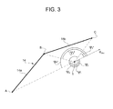
Figure 3 shows theaircraft 1 in an operative position with respect to the objective to be monitored inFigure 2 ; -
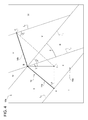
Figure 4 shows, from above, the area of land to be monitored ofFigure 2 subdivided into a plurality of operating areas for monitoring by the aircraft inFigure 1 , according to one aspect of the present invention; -
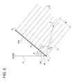
Figure 5 shows a first portion of the simple polygonal chain inFigure 2 subdivided into a plurality of sub-segments to be monitored, according to one aspect of the present invention; -
Figure 6 graphically illustrates the method of monitoring the first portion of the simple polygonal chain inFigure 2 when theaircraft 1 is in a predetermined operating area; -
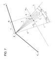
Figure 7 graphically illustrates the method of monitoring a second portion of the simple polygonal chain inFigure 2 , contiguous with the first portion inFigure 6 , when theaircraft 1 is in a predetermined operating area contiguous with the operating area inFigure 6 ; and -
Figure 8 graphically illustrates the method of monitoring the first and second portions of the simple polygonal chain inFigures 6 and7 when the monitor initiation command is given while the aircraft is flying over the operating area inFigure 6 and inFigure 7 , respectively. - According to one aspect of the present invention, a system of automatic monitoring of ground objectives is provided that is can be installed on an unmanned aerial vehicle (UAV). The monitoring system includes an image and/or video acquisition device (for example, an electro-optic stabilized turret). The monitoring system enables observation (through image and/or video shooting) of predetermined land areas (e.g. natural, such as rivers or coastal areas, or artificial, such as roads or pipelines, etc.).
- Usually, an unmanned aerial vehicle follows a predetermined flight path, planned prior to the start of the monitoring mission. Nevertheless, the route may change due to specific circumstances. According to present invention, the image/video acquisition device is automatically controlled so as to acquire images/video of the predetermined land area independently of the route followed by the unmanned aerial vehicle, and so as to always acquire the best possible view.
- The method of controlling the image/video acquisition device does not contemplate any action on the part of a ground operator.
-
Figure 1 shows anaircraft 1, in particular an unmanned aerial vehicle (UAV), equipped with an image and/or video acquisition device such as a photo/video camera 2 (hereinafter simply referred to ascamera 2, without any loss of generality). Advantageously, thecamera 2 is located on a bottom portion of theaircraft 1, or rather on a portion of the latter that, in flight, faces the ground. - The orientation of the
camera 2 towards the land areas to be monitored is automatically controlled by the monitoring system as a function of the position of theaircraft 1 in terms of latitude, longitude and altitude. This data is obtained, for example, by means of aGPS positioning system 4 mounted on board theaircraft 1. Other positioning systems capable of providing information on the position of theaircraft 1 may be used indifferently. Regarding the altitude level, it is possible to use commercially available DTED (Digital Terrain Elevation Data) devices for such computations. DTED devices are configured to associate (normally by forming a discrete grid) a measured value of altitude or height above sea level with each latitude and longitude pair (at the points considered in the discrete grid). Once this altitude level is known, thecamera 2 is able, in a manner that is in itself known, to correctly point to the objective considered at the chosen coordinates. - According to one aspect of the present invention, a zero (point) or one dimensional (straight line) geometrical element is associated with each land area to be monitored and which approximates the territorial extension along a main axis of the element. For example, a single building can be schematically represented by a point (zero dimension), while a river or a pipeline cam be represented by a simple or closed polygonal chain (one-dimensional) that follows the course of the river or pipeline.
- The applicant has verified that when the
camera 2 is pointed perpendicularly to the geometrical line (e.g. a simple polygonal chain) that defines the path in the land area to be monitored, the images that are captured are very good in terms of distortion (which is minimal). Even the direct distance (slant range) is minimized in this condition. However, because the flight path of theaircraft 1 can also be planned without taking into account the relative orientation between aircraft 1 (or camera 2) and land area to be monitored, image capture according to the criterion of perpendicularity between observation direction of thecamera 2 and the geometrical line that defines the ground path is not always possible. - According to one aspect of the present invention, a method of controlling
camera 2 is therefore provided for handling all possible situations of relative orientation betweencamera 2 and land area to be monitored. The method is performed using processing logic (e.g. a computer or microprocessor) 6 installed on board theaircraft 1 and operatively coupled to the camera 2 (to opportunely control it in terms of orientation and image capture), and to theGPS device 4 of the aircraft 1 (to acquire position data of the aircraft 1). - With reference to
Figure 2 , aland area 10 is shown that has a pipeline 12 (e.g. an oil pipeline). Hereinafter, reference shall be made in particular, to apipeline 12. Nevertheless, it is clear that what is described is similarly applicable to any (linear or linearizble) objective to be monitored. In this example, thepipeline 12 is the element that must be monitored by means of thecamera 2 of theaircraft 1. To this end, thepipeline 12 is represented geometrically and mathematically as a simplepolygonal chain 14, i.e. a line including a plurality of mutuallyconsecutive sub-segments 14a-14c extending in a rectilinear manner between respective vertices A-B-C-D. thefirst sub-segment 14a is defined as the straight line that joins vertices A and B; thesecond sub-segment 14b is defined as the straight line that joins vertices B and C; and thethird sub-segment 14c is defined as the straight line that joins vertices C and D. Vertices A, B, C and D are chosen at respective changes in direction of the pipeline 12 (i.e. at respective bends in the pipeline 12). It is clear that in the case of abrupt changes in the direction of thepipeline 12 in a very small land area, it is possible to decide not to consider each change of direction as a starting vertex of a new sub-segment, by simply approximating that portion of thepipeline 12 with a straight line that interpolates the vertices associated with each abrupt change of direction. - The
land area 10 to be monitored is divided substantially into twosub-areas polygonal chain 14. Theaircraft 1 must necessarily be flying over one of the two sub-areas (inFigure 2 , theaircraft 1 flies oversub-area 10a). According to one aspect of the present invention, it is opportune to check that two mutuallyconsecutive sub-segments 14a-14c do not form, at the point of junction, a respective angle α (angles α' and α" inFigure 2 ) of less than 90°, where this angle α is measured inside the land sub-area that theaircraft 1 is flying over (inFigure 2 , angle α' and α" are insidesub-area 10a). This condition can be checked in the phase of representation of thepipeline 12 by a simplepolygonal chain 14. If thepipeline 12 has a path variation forming an angle of less than 90°, the representation thereof by means of sub-segments must take into account the above-mentioned condition, and provide one or more transition sub-segments, each of them forming respective angles greater than 90° with the immediately previous sub-segment and with the immediately next sub-segment, (these angles are always measured inside the land sub-area that theaircraft 1 will fly over, according to the predetermined flight path). - The start of monitoring operations can be controlled automatically or by an operator-provided command.
- For example, in the case of automatic starting, monitoring will start when the
aircraft 1 is in a certain position with respect to thepipeline 12 to be monitored (this position is provided by the GPS receiver mounted on board the aircraft 1). Alternatively, by knowing the flight path and the time taken by theaircraft 1 to reach the altitude, latitude and longitude in the vicinity of thepipeline 12 to be monitored, the command to commence automatic monitoring could be provided after a certain time interval from when theaircraft 1 took off. - In the case of manual monitoring initiation, the order is given by a ground operator, via a radio link of a type in itself known.
- The representation of the
pipeline 12 by means of a simplepolygonal chain 14, as previously described, is performed using commercially available software (products that handle GIS (Geographic Information System) databases). Alternatively, this representation could be performed by a specialized operator. - Again, with reference to
Figure 1 , in addition to thecomputer 6 on board theaircraft 1, amemory 16 including a database is provided and operatively coupled to thecomputer 6. The database is suitable for storing the information that defines theschematized pipeline 12 as previously described, i.e. via a plurality ofsub-segments 14a-14c that form a simplepolygonal chain 14. In addition, respective spatial position information, in terms of geographical coordinates (in particular, latitude, longitude and height above sea level), is associated in the database with eachsub-segment 14a-14c. Even more specifically, the geographical coordinates (latitude, longitude and possibly altitude) of the vertices that delimit each sub-segment are associated with thecorresponding sub-segment 14a-14c, i.e. geographical coordinates of vertices A and B forsub-segment 14a; geographical coordinates of vertices B and C forsub-segment 14b; and geographical coordinates of vertices C and D forsub-segment 14c. Based on the latitude and longitude information of each vertex, it is easily possible to obtain information concerning the spatial extension of the associated sub-segment. - It is evident that the database can contain a plurality of information items (in the form of sub-segments forming respective simple polygonal chains) associated with a plurality of targets to be monitored other than the
pipeline 12; for example, as mentioned, land areas, buildings, infrastructures, rivers, coastal areas, roads, oil pipelines, etc. - When monitoring is manually initiated, the ground operator select a simple
polygonal chain 14 from those present in the database and the phase of tracking/tracing this simplepolygonal chain 14 by thecamera 2 commences, according to the present invention. - When monitoring is automatically initiated, the selection of a simple polygonal chain from those present in the database is performed automatically, on the basis of preset data (i.e. depending on the mission that the
aircraft 1 is performing) and the relative position between theaircraft 1 and the simplepolygonal chain 14. In particular, based on a simplepolygonal chain 14 from those present in the database (for example, the simplepolygonal chain 14 is preset in the phase of mission definition) and the position coordinates of the aircraft 1 (obtained from the GPS device 4), theprocessing logic 6 automatically selects a sub-segment 14a-14c of the simplepolygonal chain 14 from which to start the image acquisition procedure. Sub-segment 14a-14c is selected as explained below. - Upon receiving the command to start monitoring, the
processing logic 6 controls thecamera 2 automatically so as to point it towards one of the sub-segments 14a-14c of the simplepolygonal chain 14, to initiate image acquisition. The orientation of thecamera 2 depends on the position of theaircraft 1. Based on information regarding the relative geographic position between theaircraft 1 and each sub-segment 14a-14c (the geographic position of which is stored in the database of thememory 16 in terms of geographical coordinates of the start and end vertices of each sub-segment 14a-14c), theprocessing logic 6 identifies which sub-segment 14a-14c satisfies the condition whereby at least one vertex A-D "lies ahead of" theaircraft 1; in other words, given a flight direction dTRK of theaircraft 1, the coordinates of the vertex A-D that "lies ahead of" theaircraft 1 are such that theaircraft 1 has not yet reached or gone beyond this vertex A-D during its flight. With reference toFigure 3 , where only vertices A-C of the simplepolygonal chain 14 inFigure 2 are shown for simplicity (i.e. only sub-segments 14a and 14b), a vertex A-C is rejected when a respective angle Ψ (three angles Ψ1-Ψ3 are shown inFigure 3 ) has a value between 90° and 270°. - Angle Ψ is the angle between the flight (or track) direction dTRK of the
aircraft 1 at the instant considered and the (ideal) straight line that connects theaircraft 1 with the vertex A-C considered, turning in a clockwise direction. For these purposes, theaircraft 1 is also schematized as a "point", the geographical coordinates of which are the coordinates provided by theGPS device 4. - According to a different point of view, a respective vertex A-C is considered to "lie ahead of" the
aircraft 1 if angle Ψ'=360°-Ψ, between direction dTRK and the straight line that connects theaircraft 1 with the vertex A-C considered, is less than 90° or greater than 270°. Angle Ψ' is the angle travelled by the vector that indicates direction dTRK when turned in an anticlockwise direction until reaching the straight line that connects theaircraft 1 with the vertex A-C considered. InFigure 3 , three angles Ψ1'=360°-Ψ1, Ψ2'=360°-Ψ2 and Ψ3'=360°-Ψ3 are shown. - Still with reference to
Figure 3 , vertices A and B do not satisfy the condition whereby the respective angle Ψ1 and Ψ2 is inside the range 90°-270°. Instead, vertex C satisfies this condition, as angle Ψ3 between direction dTRK and the straight line that connects theaircraft 1 to vertex C is greater than 270° (i.e. Ψ3' is the only angle less than 90°). After having identified a vertex A-D that satisfies this condition (here, C), the successive vertices (i.e. the vertices following C when considered along the flight direction dTRK (here, vertex D) are not evaluated. Monitoring via thecamera 2 starts from the segment defined between the identified vertex (vertex C) and the immediately preceding vertex (vertex B), i.e. sub-segment 14b. - Once the sub-segment from which to start monitoring has been identified, the pointing of the
camera 2 depends on the reciprocal position between theaircraft 1 and the sub-segment 14b, as explained below. - With reference to
Figure 4 , the spatial area within which the pipeline 12 (schematized by the simple polygonal chain 14) extends is subdivided into a plurality of sub-areas, or zones, identified here by Roman numerals I to VI. Each sub-segment 14a-14b extends in a respective zone I-VI; however, the opposite does not occur and some zones I-VI do not include any sub-segment 14a-14c. Similarly toFigure 3 , only sub-segments 14a and 14b are shown inFigure 4 for simplicity of representation. - The procedure to delimit the various zones I-VI is as follows (similarly to that previously described, the
aircraft 1 is schematized by a point, the geographical coordinates of which are known from the GPS device 4): - angle γ is defined as the angle between sub-segment 14a and the straight line passing between the
aircraft 1 and vertex A (with γ between +180° and -180°); - angle ρ is defined as the angle between a straight line L1 (where L1 is orthogonal to sub-segment 14a and passes through vertex B) and the straight line passing between the
aircraft 1 and vertex B (with ρ between +180° and -180°); - angle γ1 is defined as the angle between a straight line L2 (where L2 is orthogonal to sub-segment 14b and passes through vertex B) and the straight line passing between the
aircraft 1 and vertex B (with γ1 between +180° and -180°); - angle ρ1 is defined as the angle between a straight line L3 (where L3 is orthogonal to sub-segment 14b and passes through vertex C) and the straight line passing between the
aircraft 1 and vertex C (with ρ1 between +180° and -180°). - In greater detail, angle γ is inside the triangle formed by the straight lines that connect the
aircraft 1 with vertices A and B and by sub-segment 14a, i.e. angle γ extends completely withinsub-area 10a. Similarly, angles γ1, ρ, ρ1 and δ also extend completely withinsub-area 10a. - The subdivision of the
land area 10 into zones I-VI is performed as described below. - Zone II is the area that comprises sub-segment 14a and is defined as follows: in
sub-area 10a, zone II is the zone between straight line L4 orthogonal to sub-segment 14a at vertex A and straight line L2; insub-area 10b, zone II is the zone between straight line L4 and straight line L1. - Zone V is the area that comprises sub-segment 14b and is defined as follows: in
sub-area 10a, zone V is the zone between straight line L1 and straight line L3; insub-area 10b, zone V is the zone between straight line L2 and straight line L3. - Zone III is the area comprised between straight line L1 and straight line L2 in
sub-area 10a. - Zone IV is the area between straight line L1 and straight line L2 in
sub-area 10b. - Zone I is the area external to the areas subtended by sub-segments 14a and 14b, and is only delimited by straight line L4.
- Zone VI is the area external to the areas subtended by sub-segments 14a and 14b, and is delimited by straight line L3 (and L1).
- Orientation of the
camera 2 varies depending on the zone I-VI in which theaircraft 1 is flying. In particular, the operating mode of thecamera 2 changes according to the following table (1).Table (1) γ ρ γ1 ρ1 zone mode segment vertex |γ|≥90° - ≥0° - I Fix A |γ|<90° ≥0° ≥0° - II Leg 14a - ≥0° <0° - III Int - <0° ≥0° - IV Fix B - <0° <0° ≥0° V Leg 14b - <0° - <0° VI Fix C - In zones I and IV, the
camera 2 is operated in "Fix" mode, whereby it is controlled so as to point in a fixed mode to a respective vertex (i.e. the vertex located "ahead of" theaircraft 1, based on the current coordinates of theaircraft 1, the coordinates of the vertex considered and the flight direction of theaircraft 1, as described with reference toFigure 3 ). Only in the case of zone VI, considering vertex C as the last vertex to be monitored and a flight direction away from zone V, is thecamera 2 pointed "backwards" from theaircraft 1, pointing in fixed mode to vertex C. This is not applicable in the case where there are other sub-segments to be monitored after vertex C. - In the case where the
aircraft 1 is in zone I and has a flight direction dTRK towards zone II (or in the opposite direction, away from zone II, and assuming that there are no further sub-segments to be monitored), then thecamera 2 is pointed in fixed mode to vertex A. - In the case where the
aircraft 1 is in zone VI and has a flight direction dTRK towards zone V (or in the opposite direction, away from zone V, and assuming that there are no further sub-segments to be monitored), then thecamera 2 is pointed in fixed mode to vertex C. - In the case where the aircraft is in zone IV (i.e. at the end of monitoring a sub-segment 14a or 14b), the
camera 2 is pointed towards vertex B independently of the flight direction dTRK. - It should be noted how the above-mentioned zones I, IV and VI are such that when the
aircraft 1 is in one of them, thecamera 2 is not able to point perpendicularly onto any sub-segment 14a, 14b. Instead, if theaircraft 1 is in one of the other zones, then it is possible to point perpendicularly onto one ofsub-segments - When the
aircraft 1 is in zone II or V, thecamera 2 is controlled in "Leg" mode, whereby thecamera 2 is in the condition of being able to point perpendicularly onto one of therespective sub-segments 14a (for zone II) or 14b (for zone V). - The
control logic 6 controls the pointing of thecamera 2 in "Leg" mode based on the following data: - latitude LATA and longitude LONA of vertex A and latitude LATB and longitude LONB of vertex B for acquiring images of sub-segment 14a;
- latitude LATB and longitude LONB of vertex B and latitude LATC and longitude LONC of vertex C for acquiring images of sub-segment 14b;
- latitude LATV and longitude LONV of the
aircraft 1; - discretization step "d", the definition of which is required by this method and which denotes the ground spacing of the discrete points towards which the
camera 2 will be pointed between the vertices of the sub-segments (e.g. A and B). - To determine the coordinates of the point to be monitored, the
control logic 6 performs the procedure described with reference toFigure 5 (referring to sub-segment 14a in particular). - With reference to
Figure 5 , sub-segment 14a, delimited by vertices A-B, is subdivided into a plurality NA of discrete portions Ai, each of which has a length given by the discretization step d. The number NA of discrete portions Ai is given by AB/d (where AB is the length of sub-segment 14a). - Knowledge of the geographical coordinates of vertices A and B allows computing, in a known manner, the value of length AB, as well as the value of angle β between sub-segment 14a and the geographical north direction (arrow N in
Figure 5 ).
A known method for computing the value of length AB is provided, for example, by T. Vincenty, "Direct and Inverse Solutions of Geodesics on the Ellipsoid with Application of Nested Equations", Survey Review, vol. 23, no. 176, April 1975, pp. 88-93. - The same method can be used to compute, based on the geographical coordinates of vertex A and of the
aircraft 1, the value of (rectilinear) distance r between vertex A and the current position of theaircraft 1, as well as the value of angle ξ between the north direction and straight line r. - Distance h is then calculated, which is the length of the straight line between vertex A and the projection of the point where the
aircraft 1 is located onto sub-segment 14a. The angle θ between the straight line L4 (orthogonal to sub-segment 14a and passing through vertex A) and straight line r is calculated as follows:
Distance h is calculated as follows:
- The value of h thus calculated enables determining which of the three discrete portions Ai must be observed via the
camera 2. Given the value taken by h, the following conditions should be noted: - h≤0, then we are in an area in which the
camera 2 is operated in "Fix" mode, pointing to vertex A (zone I); - 0<h<AB, then Ai corresponds to (h/d)+1 (in the event of h/d being a decimal number, only the integer part is considered);
- h≥AB, then we are in an area in which the
camera 2 is operated in "Fix" mode pointing to vertex B (in the case where B corresponds to the last vertex of the line to observe). - In the situation where 0<h<AB: Ai=A1=1 is the first discrete portion starting from vertex A; Ai=A2=2 is the second discrete portion starting from vertex A; and so on, where Ai=AM=M is the M' th discrete portion starting from vertex A.
- The value of Ai thus calculated is used to calculate the value of distance AA i between vertex A and the midpoint of the associated discrete portion Ai as follows:

where the median point of each discrete portion Ai, as identified by the spatial position of the respective discrete portion Ai, is considered. - It is then possible to calculate the coordinates of the point to be monitored, or rather the point for which it desired to capture one or more images or video via the
camera 2. In particular, the latitude LATAi and longitude LONAi of the discrete portion Ai to be monitored are based on the values of latitude LATA and longitude LONA of vertex A, the value of angle β and the value of distance AA i . - The known method by T. Vincenty, "Direct and Inverse Solutions of Geodesics on the Ellipsoid with Application of Nested Equations" can be used to calculate the value of distance AA i . The same method also enables expressing the latitude LATAi and longitude LONAi of discrete portion Ai as a function of vertex A, the value of angle β and the value of distance AA i .
- Again, with reference to the table (1), zone III is an intermediate zone in which the camera operates in "Int" mode. This zone is a transition area between zones II and V in which the
camera 2 operates in "Leg" mode. When theaircraft 1 is in zone III, thecamera 2 is controlled so as to acquire images of both sub-segment 14a and sub-segment 14b at an increased rate. In fact, in zone III the condition of perpendicularity between the direction of orientation of thecamera 2 and the sub-segments 14a and 14b occurs for both sub-segments 14a and 14b. - The definition of the zones allows extending the concept of improved observability of the ground line, including those areas of land in which the above-mentioned perpendicularity condition is not guaranteed, or those in which it is satisfied by several segments of the ground line (as happens, for example, in zone III). The image acquisition rate depends on the position of the aircraft (and consequently on its ground speed), and is therefore constant in the case of an aircraft that moves in space with uniform motion. In the areas of zones where perpendicularity is not satisfied, the camera is controlled to constantly frame the point nearest the aircraft. Instead, in zones where perpendicularity is satisfied by several points, the image acquisition rate is increased to allow observation of entire segments of the line (e.g. both sub-segments 14a and 14b).
- With reference to
Figure 6 , the value of angle δ=ρ-γ1 (i.e. the angle between L1 and L2) is given by the absolute value of the difference δ=ρ-γ1. It should be noted that the difference δ=ρ-γ1 is positive for the situation shown inFigure 6 , where angle ABC (with vertex on B inside sub-area 10a) is less than 180°. Whereas if the opposite case is considered, in which angle ABC (always with vertex on B inside sub-area 10a) is greater than 180°, the difference δ=ρ-γ1 is negative. The angular size of the intermediate zone (δ) is therefore the absolute value of the difference in orientation of the two successive segments (AB and BC) correlated with angles ρ and γ1. - Zone III is divided in half, into two sub-areas in which the first subzone III1 is comprised between straight line L2 and straight line Lδ that divides angle δ in half, and the second subzone III2 is comprised between straight line L1 and straight line Lδ.
- To determine the coordinates of the point to be monitored, when the
aircraft 1 enters subzone III1 from zone II, the following procedure is used. - When entering zone III, the number of discrete portions Ai (of sub-segment 14a) already passed over and monitored is known. The remaining discrete portions Ai of sub-segment 14a still to be monitored must be monitored (i.e. their respective images must be captured by the camera 2) until the
aircraft 1 is in subzone III1 of zone III. By dividing δ/2 by the number of remaining discrete portions Ai, it is possible to determine the magnitude ν of the radial sectors of subzone III1 within which the camera must be controlled in order to capture an image for each of the remaining discrete portions Ai, in order to complete the monitoring ofsub-segment 14a. In other words, subzone III1 is subdivided into a plurality of radial sectors, each one of them defined by respective lines Lδ/2_A, that theaircraft 1 passes over during its flight. The passage of pointing thecamera 2 from a discrete portion Ai to a successive discrete portion Ai+1 corresponds to the transition from one radial sector to another in subzone III1. - In order to identify the radial sector where the aircraft is flying, and consequently the point Ai to be monitored, the following procedure is used. The value of angle µ is calculated, defined as the angle between the straight line L2 and the straight line rB passing between the
aircraft 1 and vertex B (in the case shown inFigure 6 , straight line rB is superimposed on L2). Mathematically, angle µ is calculated in the following manner: - µ=-γ1 if the azimuth of segment AB with respect to north is less than the azimuth of segment BC with respect to north (the case of
Figure 6 ); and µ=180°-|γ1| if the azimuth of AB with respect to north is greater than the azimuth of segment BC with respect to north. - In order to calculate the radial sector in which the
aircraft 1 is flying, the following procedure is used: angle µ (a function of the aircraft's current position) is divided by the magnitude of each radial sector ν (a function of the line's geometry); the integer value of the result corresponds to the index "i" indicating the point Ai to be monitored. Specifically:
where "int" indicates the operation by which the decimal digits deriving from the division operation are discarded and only the integer part is considered. - With reference to
Figure 6 , it is not possible to acquire images perpendicularly to each sub-segment Ai in any radial sector of subzone III1. Images are only acquired perpendicularly in "Leg" zones. - Reaching straight line Lδ corresponds to the
aircraft 1 completing angle δ/2, and also corresponds to entering subzone III2. - Entry of the
aircraft 1 in subzone III2 corresponds to the start of monitoring sub-segment 14b. Similarly to that described with reference toFigure 5 , sub-segment 14b is also discretized into a plurality of discrete portions Bi having the same spatial extension "d" (discretization step). Subzone III2 is subdivided into a plurality of radial sectors, each one of them defined by respective lines Lδ/2_B, which theaircraft 1 will cross during its flight (Figure 7 ). The passage of pointing thecamera 2 from a discrete portion Bi to a successive discrete portion Bi+1 corresponds to the transition from one radial sector to another in subzone III2. The projection of theaircraft 1 onsub-segment 14b at the exit from zone III / entry to zone V is not known beforehand and depends on the course followed by theaircraft 1. In consequence, the discrete portion Bi that thecamera 2 must point to (perpendicularly) upon exit from zone III / entry to zone V is also unknown. To this end, an approximation is performed whereby it is assumed that theaircraft 1 flies on a course in subzone III2 having a direction corresponding to the flight direction assumed on passage from subzone III1 to subzone III2. It is thus possible to determine a geographic position K beforehand, corresponding to the passage from zone III to zone V, which corresponds to point Bp projected on sub-segment 14b. - The procedure to calculate the coordinates of the point Bp of sub-segment 14b to be monitored upon entry to subzone III2 is as follows.
- The distance "m" between vertex B and the position that the
aircraft 1 has assumed on straight line L2, namely upon entering subzone III1, is calculated. This operation is possible on the basis of the latitude and longitude values of vertex B (known) and those assumed by aircraft 1 (known via theGPS device 4 and stored in memory 16). - Then, values are calculated for angles τ and ε, respectively formed by the intersection of straight line L2 with the direction (assumed straight at the point of intersection) of the
aircraft 1 and by the intersection of straight line L1 with the direction (assumed straight at the point of intersection) of theaircraft 1. Since m/sin(ε)=n/sin(τ), the distance "n" between vertex B and the point K of assumed transition from zone III to zone V is given by the following relation:
- The distance h1 between vertex B and point Bp, on sub-segment 14b is given by:

- Distance h1 comprises a number of discrete portions Bi, given by h1/b. In the case where the operation h1/b supplies a decimal number, only the integer part is considered. The number of discrete portions Bi thus obtained represents the discrete portions Bi that must be monitored in subzone III2, within angle δ/2. The width, measured along the assumed flight direction dTRK, of each radial sector in subzone III2 is obtained by dividing δ/2 by the number of discrete portions Bi, given by h1/b (considering only the integer part).
- From
Figure 6 it can be noted that, in subzones III1 and III2, the permanence of the aircraft in each radial sector is shorter than its permanence in the discrete portions Ai (and, similarly, Bi), as, especially nearsegments camera 2 is greater than the image acquisition rate in zones II and V. Furthermore, depending on the flight direction of the aircraft, the image acquisition rate in subzone III1 can be different (greater in the example inFigure 6 ) from that in subzone III2. - After leaving zone III, the
aircraft 1 enters zone V. Zone V is similar to zone I and directing thecamera 2 orthogonally to the discrete portions Bi takes place in a similar manner to that described with reference to zone I,Figure 5 . - There is a special condition when the monitoring method is started while the
aircraft 1 is in an intermediate zone "Int", for example, in zone III. In fact, in this event, thecamera 2 must be controlled to scan a final part of the sub-segment 14a (close to vertex B) in the case where the aircraft is in subzone III1, or scan an initial part of sub-segment 14b (close to vertex B) in the case where the aircraft is in subzone III2. - As shown in
Figure 8 , when theaircraft 1 is in subzone III1 and receives the command to start monitoring in this subzone III1, thecontrol logic 6 operates as follows. - The angle Φ, which is the angle between straight line rB (which connects the
aircraft 1 with vertex B) and straight line Lδ, is calculated as follows:
where ρ (seeFigure 4 ) is the angle between straight line L1 and the straight line that connects theaircraft 1 with vertex B. - The length lr of the portion of sub-segment 14a comprised between vertex B and the point J of intersection between sub-segment 14a and a straight line rJ orthogonal to sub-segment 14a and passing through the point where the
aircraft 1 is located, is then calculated. The value of lr is given by:
where rB is, as stated, the (rectilinear) distance between theaircraft 1 and vertex B. - Then, the number NAi of discrete portions Ai present within the portion of length lr of sub-segment 14a is calculated.
- This value is obtained as:

where "int" indicates the operation by which the decimal digits deriving from the division operation are discarded and only the integer part is considered. - Furthermore, by dividing the value of angle Φ by the value of NAi it is possible to calculate the angular distance Φ1 covered by the
aircraft 1 in each radial sector LΦ. When theaircraft 1 is in one of the radial sectors LΦ, thecamera 2 will be controlled to capture images of a respective discrete portion Ai. In other words, one and only one discrete portion Ai to be monitored is associated with each radial sector LΦ. The first radial sector LΦ starting from straight line rB is associated with the first discrete portion Ai starting from point J, the second radial sector LΦ starting from straight line rB is associated with the second discrete portion Ai starting from point J, and so on. The aircraft passes from one radial sector LΦ to the next radial sector LΦ+1 every "Φ1" degrees, until straight line Lδ is reached, i.e. until ρ=δ/2. The passage from subzone III1 to subzone III2 is handled as already described with reference toFigure 7 . - There is a further special condition when the monitoring method is started while the
aircraft 1 is in subzone III2 of intermediate zone III. In this event, thecamera 2 is controlled to scan sub-segment 14b. - As shown in
Figure 8 , when theaircraft 1 is in subzone III2 (in this case, the aircraft is identified by reference numeral 1') and receives the command to start monitoring in this subzone III2, thecontrol logic 6 operates as follows. - The coordinates are calculated for point W, given by the projection onto sub-segment 14b of the point where the aircraft 1' is located (i.e. the coordinates of the point W of intersection of sub-segment 14b with a straight line orthogonal to sub-segment 14b and passing through the point where the aircraft 1' is located). The monitoring of
sub-segment 14b starts at this point W, proceeding towards vertex C in a similar manner to that already described with reference toFigures 5 , i.e. for a "Leg" zone. - It is evident from the description that the method according to the present invention represents a significant evolution with respect to that reported in the literature and known in the state of the art.
- In particular, the system and the method according to the present invention enable complete automation of the monitoring procedures performed by an aircraft with or without a pilot, always ensuring the best camera angle for image capture.
- Furthermore, the automation inherent in the method of the present invention enables reducing the workload of the operator responsible for managing the camera. With this method, the controls that must be handled by the operator (if available) will mainly concern selection of the optics to use for monitoring (for example, electro-optics or infrared) and setting up the zoom. Finally, as the monitoring method described is not constrained by the path (planned or otherwise) flown by the aircraft, but depends only on the geographic position of the aircraft, the operator will have flexibility in altering the flight path according to mission conditions without having to worry about the pointing of the
camera 2. In this way, the operator can concentrate on the analysis and interpretation of the images acquired during monitoring. - Moreover, within the field of unmanned aerial vehicles, automation is a key element tightly bound to the technological maturity of the system. On the other hand, the low costs of these aircraft are one of the fundamental factors that have resulted in their development and which could contribute in the future to establishing their diffusion both in the civil field and in the military field. In fact, unlike traditional aircraft, the operative flexibility could give rise to solutions where, for example, an operator becomes responsible both for handling the aircraft and the available sensors. Other solutions aim at having just one operator capable of simultaneously managing several aircraft or several sensors (of one or more aircraft). The method described in the present invention is able to contribute to achieving these objectives.
- Finally, it is clear that modifications and variants may be made to the invention described and illustrated herein, without departing from the scope of the invention, as defined in the appended claims.
Claims (17)
- A system for monitoring linear ground objectives (12), configured to be installed on an aircraft (1) adapted to fly over a geographic area (10), comprising:- an image and/or video capture device (2) that can be operatively coupled to said aircraft (1);- a positioning device (4) suitable for being installed on the aircraft (1) and configured to provide first geographical coordinates (LATV, LONV) of said aircraft (1) identifying a current position of the aircraft (1) along a flight path direction (dTRK);- a memory (16) storing second (LATA, LONA), third (LATB, LONB) and fourth (LATC, LONC) predetermined geographical coordinates of at least a first (A), a second (B) and a third (C) ground location respectively, said second and third geographical coordinates defining respective vertices (A, B) of a first straight objective (14a) to be monitored, and said third and fourth geographical coordinates defining respective vertices (B and C) of a second straight objective (14b), contiguous with the first straight objective, to be monitored such that the first and the second straight objectives (14a and 14b) form a simple polygonal chain (14);- processing logic (6) operatively connected to the capture device (2), the positioning device (4) and the memory (16), and configured to:(i) acquire, from the positioning device (4), the first geographical coordinates identifying a current position of the aircraft along said flight path direction (dTRK);(ii) acquire, from the memory (16), the second, the third and the fourth predetermined geographical coordinates;(iii) subdivide the geographic area (10) into a first and a second geographic sub-area (10a and 10b) separated from each other by said simple polygonal chain (14);(iv) determine if a first ideal straight line exists, the first ideal straight line passing through the first geographical coordinates and orthogonally intersecting the first straight objective (14a);(v) if said first ideal straight line exists, then direct said capture device (2) towards the first straight objective along the direction defined by said first ideal straight line, otherwise perform operation (vi) to(vi) determine a second ideal straight line that passes through the first geographical coordinates and orthogonally intersects the second straight objective, and direct said capture device (2) towards the second straight objective along the direction defined by said second ideal straight line.
- A monitoring system according to claim 1, wherein the processing logic (6) is further configured to:subdivide the first straight objective (14a) into a plurality of first straight sub-segments (Ai);subdivide the second straight objective (14b) into a plurality of second straight sub-segments (Bi); andperiodically update the first geographical coordinates of the aircraft along said route by means of the positioning device (4),said steps of determining if the first ideal straight line or the second ideal straight line exists being carried out at each first or, respectively, second straight sub-segment (Ai or Bi).
- A monitoring system according to claim 1 or 2, wherein operation (iv) includes:computing respective first and second intermediate straight lines, each of them passing through a point defined by the first geographical coordinates (LATV, LONV) and through a respective point (A, B) identified by the second (LATA, LONA) and third (LATB, LONB) geographical coordinates; anddetermining if at least one of said first and second intermediate straight lines forms at least a respective angle of less than 90° with the flight path direction (dTRK) and, if so, determining said first ideal straight line.
- A monitoring system according to any of the preceding claims, wherein operation (vi) includes:computing a third intermediate straight line passing through a point identified by the first geographical coordinates (LATV, LONV) and a point (C) identified by the fourth geographical coordinates (LATC, LONC);verifying whether the third intermediate straight line forms at least an angle of less than 90° with the flight path direction (dTRK) and, if so,determining said second ideal straight line.
- A monitoring system according to any of the preceding claims, wherein the processing logic (6) is further configured to define a first operating area (II) associated with the first straight objective (14a), a second operating area (V) associated with the second straight objective (14b), and a third operating area (III),
said first operating area (II) being comprised between a boundary line L4 orthogonal to the first straight objective (14a) and passing through the second geographical coordinates (LATA, LONA), and a boundary line L1 orthogonal to the first straight objective (14a) and passing through the third geographical coordinates (LATB, LONB),
said second operating area (V) being comprised between a boundary line L2 orthogonal to the second straight objective (14b) and passing through the third geographical coordinates (LATB, LONB), and a boundary line L3 orthogonal to the second straight objective (14b) and passing through the fourth geographical coordinates (LATC, LONC), and
said third operating area (III) being comprised between boundary line L2 and boundary line L1 and being defined by the partial overlapping of the first and second operating areas, wherein the processing logic (6) is further configured to:control said capture device (2) to acquire images associated with the first straight objective (14a) at a first acquisition rate when the aircraft (1) flies over said first operating area (II), but not said third operating area (III);control said capture device (2) to acquire images associated with the second straight objective (14b) at a second acquisition rate when the aircraft (1) flies over said second operating area (V), but not said third operating area (III); andcontrol said capture device (2) to acquire images associated with both the first straight objective (14a) and the second straight objective (14b) at a third acquisition rate, greater than the first and the second acquisition rates, when the aircraft (1) flies over said third operating area (III). - A monitoring system according to claim 5, wherein the processing logic (6) is further configured to:control said capture device (2) to acquire images associated with the first straight objective (14a) at an acquisition rate greater than the first acquisition rate when the aircraft (1) flies over a first portion (III1), contiguous with the first operating area, of said third operating area (III); andcontrol said capture device (2) to acquire images associated with the second straight objective (14b) at an acquisition rate greater than the second acquisition rate when the aircraft (1) flies over a second portion (III2), contiguous with said first portion (III1), of said third operating area (III).
- A monitoring system according to claim 5 or 6, wherein, when the aircraft (1) flies over the first geographic sub-area (10a), the processing logic (6) is further configured to:compute the value of an angle γ between the first straight objective (14a) and the first intermediate straight line and extending only in the first geographic sub-area (10a);compute the value of an angle ρ between boundary line L1 and the second intermediate straight line and extending only in the first geographic sub-area (10a);compute the value of an angle γ1 between boundary line L2 andthe second intermediate straight line and extending only in the first geographic sub-area (10a);compute the value of an angle ρ1 between boundary line L3 and the third intermediate straight line and extending only in the first geographic sub-area (10a);compute the value of an angle δ between boundary line L1 andboundary line L2 and extending only in the first geographic sub-area (10a);control said capture device (2) so as to acquire images associated with the first straight objective (14a) at the first acquisition rate when the aircraft (1) flies over the first operating area (II), but not the third operating area (III) and when |γ|<90°, ρ≥0° and |γ1|≥0°;control said capture device (2) so as to acquire images associated with the second straight objective (14b) at the second acquisition rate when the aircraft (1) flies over the second operating area (V), but not the third operating area (III) and when ρ<0°, γ1<0° and ρ1≥0°;control said capture device (2) so as to acquire images associated with the first straight objective (14a) at the third acquisition rate when the aircraft (1) flies over the third operating area (III) and when ρ>δ/2;control said capture device (2) so as to acquire images associated with the second straight objective (14B) at the fourth acquisition rate when the aircraft (1) flies over the third operating area (III) and when ρ<δ/2.
- A monitoring system according to any of claims 5-7, wherein the processing logic (6) is further configured to:define a fourth operating area (IV) in the second geographic sub-area (10b) between boundary line L1 and boundary line L2;define a fifth operating area (I) in a geographic area external to the first and the second geographic sub-areas (10a and 10b) and delimited by boundary line L4;define a sixth operating area (VI) in a geographic area external to the first and the second geographic sub-areas (10a and 10b) and delimited by boundary line L3;control said capture device (2) to acquire images associated with the second ground location (B) when the aircraft (1) flies over said fourth operating area (IV);control said capture device (2) to acquire images associated with the first ground location (A) when the aircraft (1) flies over said fifth operating area (I); andcontrol said capture device (2) to acquire images associated with the third ground location (C) when the aircraft (1) flies over said sixth operating area (VI).
- A system according to any of the preceding claims, further including a device for computing the digital terrain elevation data (DTED) configured to associate with each of said second (LATA, LONA), third (LATB, LONB) and fourth (LATC, LONC) geographical coordinates, a respective height above sea level.
- A method for monitoring linear ground objectives (12) from an aircraft (1) adapted to fly over a geographic area (10) and comprising: an image and/or video capture device (2); a positioning device (4) configured to provide first geographical coordinates (LATV, LONV) of said aircraft (1) identifying a current position of the aircraft (1) along a flight path direction (dTRK); a memory (16) storing second (LATA, LONA), third (LATB, LONB) and fourth (LATC, LONC) predetermined geographical coordinates of at least a first (A), a second (B) and a third (C) ground location, respectively, said second and third geographical coordinates defining respective vertices (A, B) of a first straight objective (14a) to be monitored, and said third and fourth geographical coordinates defining respective vertices (B, C) of a second straight objective (14b), contiguous with the first straight objective, to be monitored, such that the first and the second straight objectives (14a and 14b) form a simple polygonal chain (14),
said method comprising the steps of:(i) acquiring, from the positioning device (4), the first geographical coordinates identifying a current position of the aircraft along said flight path direction (dTRK);(ii) acquiring, from the memory (16), the second, third and fourth predetermined geographical coordinates;(iii) subdividing the geographic area (10) into a first and a second geographic sub-area (10a and 10b) separated from each other by said open simple polygonal chain (14);(iv) determining if a first ideal straight line exists that passes through the first geographical coordinates and that orthogonally intersects the first straight objective (14a);(v) if said first ideal straight line exists, then directing said capture device (2) towards the first straight objective along the direction defined by said first ideal straight line, otherwise performing operation (vi) of(vi) determining a second ideal straight line that passes through the first geographical coordinates and that orthogonally intersects the second straight objective and directing said capture device (2) towards the second straight objective along the direction defined by said second ideal straight line. - A monitoring method according to claim 10, further comprising the steps of:subdividing the first straight objective (14a) into a plurality of first straight sub-segments (Ai);subdividing the second straight objective (14b) into a plurality of second straight sub-segments (Bi); andperiodically updating the first geographical coordinates of the aircraft along said flight path direction by means of the positioning device (4),said steps of determining if the first ideal straight line or the second ideal straight line exists being periodically carried out at each first or, respectively, second straight sub-segment (Ai, Bi).
- A monitoring method according to claim 10 or 11, wherein step (iv) includes:computing respective first and second intermediate straight lines passing through a point identified by the first geographical coordinates (LATV, LONV) and through a respective point (A, B) defined by the second (LATA, LONA) and, respectively, the third (LATB, LONB) geographical coordinates; anddetermining if at least one of said first and second intermediate straight lines forms at least a respective angle of less than 90° with the flight path direction (dTRK) and, if so, determining said first ideal straight line.
- A monitoring method according to any of claims 10-12, wherein step (vi) includes:computing a third intermediate straight line passing through a point identified by the first geographical coordinates (LATV, LONV) and a point (C) identified by the fourth geographical coordinates (LATC, LONC);checking whether the third intermediate straight line forms at least an angle of less than 90° with the flight path direction (dTRK); and, if so,determining said second ideal straight line.
- A monitoring method according to any of claims 10-13, further comprising the steps of defining a first operating area (II) associated with the first straight objective (14a), a second operating area (V) associated with the second straight objective (14b), and a third operating area (III), said first operating area (II) being comprised between a boundary line L4 orthogonal to the first straight objective (14a) and passing through the second geographical coordinates (LATA, LONA), and a boundary line L1 orthogonal to the first straight objective (14a) and passing through the third geographical coordinates (LATB, LONB),
said second operating area (V) being comprised between a boundary line L2 orthogonal to the second straight objective (14b) and passing through the third geographical coordinates (LATB, LONB), and a boundary line L3 orthogonal to the second straight objective (14b) and passing through the fourth geographical coordinates (LATC, LONC), and
said third operating area (III) being comprised between boundary line L2 and boundary line L1 and being defined by the partial overlapping of the first and second operating areas, the method further comprising the steps of:controlling said capture device (2) to acquire images associated with the first straight objective (14a) at a first acquisition rate when the aircraft (1) flies over said first operating area (I), but not said third operating area (III);controlling said capture device (2) to acquire images associated with the second straight objective (14b) at a second acquisition rate when the aircraft (1) flies over said second operating area (V), but not said third operating area (III); andcontrolling said capture device (2) to acquire images associated with the first straight objective (14a) at a third acquisition rate, greater than the first and the second acquisition rates, when the aircraft (1) flies over said third operating area (III). - A monitoring method according to claim 14, further comprising the steps of:controlling said capture device (2) to acquire images associated with the first straight objective (14a) at an acquisition rate greater than the first acquisition rate when the aircraft (1) flies over a first portion (III1), contiguous with the first operating area, of said third operating area (III); andcontrolling said capture device (2) to acquire images associated with the second straight objective (14b) at an acquisition rate greater than the second acquisition rate when the aircraft (1) flies over a second portion (III2),contiguous with said first portion, of said third operating area (III).
- A monitoring method according to claim 14 or 15, wherein, when the aircraft (1) flies over the first geographic sub-area (10a), the method further comprises the steps of:computing the value of an angle γ between the first straight objective (14a) and the first intermediate straight line andextending only in the first geographic sub-area (10a);computing the value of an angle ρ between boundary line L1 and the second intermediate straight line, and extending only in the first geographic sub-area (10a);computing the value of an angle γ1 between boundary line L2 and the second intermediate straight line and extending only in the first geographic sub-area (10a);computing the value of an angle ρ1 between boundary line L3 and the third intermediate straight line and extending only in the first geographic sub-area (10a);computing the value of an angle δ between boundary line L1 and boundary line L2 and extending only in the first geographic sub-area (10a);controlling said capture device (2) so as to acquire images associated with the first straight objective (14a) at the first acquisition rate when the aircraft (1) flies over the first operating area (II), but not the third operating area (III) and with |γ|<90°, ρ≥0° and |γ|≥0°;controlling said capture device (2) so as to acquire images associated with the second straight objective (14b) at the second acquisition rate when the aircraft (1) flies over the second operating area (V), but not the third operating area (III) and with ρ<0°, γ1<0° and p1≥0°;controlling said capture device (2) so as to acquire images associated with the first straight objective (14a) at the third acquisition rate when the aircraft (1) flies over the third operating area (III) and with ρ>δ/2; andcontrolling said capture device (2) so as to acquire images associated with the second straight objective (14b) at the fourth acquisition rate when the aircraft (1) flies over the third operating area (III) and with ρ<δ/2.
- A monitoring method according to any of claims 14-16, further comprising the steps of:defining a fourth operating area (IV) in the second geographic sub-area (10b) between boundary line L1 and boundary line L2;defining a fifth operating area (I) in a geographic area external to the first and the second geographic sub-areas (10a and 10b) and delimited by boundary line L4;defining a sixth operating area (VI) in a geographic area external to the first and the second geographic sub-areas (10a and 10b) and delimited by boundary line L3;controlling said capture device (2) to acquire images associated with the second ground location (B) when the aircraft (1) flies over said fourth operating area (IV);controlling said capture device (2) to acquire images associated with the first ground location (A) when the aircraft (1) flies over said fifth operating area (I); andcontrolling said capture device (2) to acquire images associated with the third ground location (C) when the aircraft (1) flies over said sixth operating area (VI).
Applications Claiming Priority (1)
| Application Number | Priority Date | Filing Date | Title |
|---|---|---|---|
| IT000763A ITTO20130763A1 (en) | 2013-09-20 | 2013-09-20 | SYSTEM AND METHOD OF AUTOMATIC MONITORING OF LAND LINEAR LENSES FOR A REMOTE AIRCRAFT AIRCRAFT |
Publications (2)
| Publication Number | Publication Date |
|---|---|
| EP2873947A1 true EP2873947A1 (en) | 2015-05-20 |
| EP2873947B1 EP2873947B1 (en) | 2019-02-27 |
Family
ID=49817184
Family Applications (1)
| Application Number | Title | Priority Date | Filing Date |
|---|---|---|---|
| EP14185674.0A Active EP2873947B1 (en) | 2013-09-20 | 2014-09-19 | System and method of automatic monitoring of linear ground objectives for a remotely piloted aircraft |
Country Status (3)
| Country | Link |
|---|---|
| EP (1) | EP2873947B1 (en) |
| ES (1) | ES2715012T3 (en) |
| IT (1) | ITTO20130763A1 (en) |
Cited By (3)
| Publication number | Priority date | Publication date | Assignee | Title |
|---|---|---|---|---|
| CN107357316A (en) * | 2017-08-16 | 2017-11-17 | 湖南城市学院 | A kind of method for controlling UAV locking specific region to obtain photo |
| CN109782786A (en) * | 2019-02-12 | 2019-05-21 | 上海戴世智能科技有限公司 | A kind of localization method and unmanned plane based on image procossing |
| CN121594895A (en) * | 2026-01-29 | 2026-03-03 | 航天时代低空科技有限公司 | Unmanned aerial vehicle true high route track smooth processing method, system, equipment and medium for complex terrain |
Citations (1)
| Publication number | Priority date | Publication date | Assignee | Title |
|---|---|---|---|---|
| US20100305782A1 (en) * | 2009-05-27 | 2010-12-02 | David Linden | Airborne right of way autonomous imager |
-
2013
- 2013-09-20 IT IT000763A patent/ITTO20130763A1/en unknown
-
2014
- 2014-09-19 ES ES14185674T patent/ES2715012T3/en active Active
- 2014-09-19 EP EP14185674.0A patent/EP2873947B1/en active Active
Patent Citations (1)
| Publication number | Priority date | Publication date | Assignee | Title |
|---|---|---|---|---|
| US20100305782A1 (en) * | 2009-05-27 | 2010-12-02 | David Linden | Airborne right of way autonomous imager |
Non-Patent Citations (1)
| Title |
|---|
| T. VINCENTY: "Direct and Inverse Solutions of Geodesics on the Ellipsoid with Application of Nested Equations", SURVEY REVIEW, vol. 23, no. 176, April 1975 (1975-04-01), pages 88 - 93 |
Cited By (4)
| Publication number | Priority date | Publication date | Assignee | Title |
|---|---|---|---|---|
| CN107357316A (en) * | 2017-08-16 | 2017-11-17 | 湖南城市学院 | A kind of method for controlling UAV locking specific region to obtain photo |
| CN109782786A (en) * | 2019-02-12 | 2019-05-21 | 上海戴世智能科技有限公司 | A kind of localization method and unmanned plane based on image procossing |
| CN109782786B (en) * | 2019-02-12 | 2021-09-28 | 上海戴世智能科技有限公司 | Positioning method based on image processing and unmanned aerial vehicle |
| CN121594895A (en) * | 2026-01-29 | 2026-03-03 | 航天时代低空科技有限公司 | Unmanned aerial vehicle true high route track smooth processing method, system, equipment and medium for complex terrain |
Also Published As
| Publication number | Publication date |
|---|---|
| ITTO20130763A1 (en) | 2015-03-21 |
| ES2715012T3 (en) | 2019-05-31 |
| EP2873947B1 (en) | 2019-02-27 |
Similar Documents
| Publication | Publication Date | Title |
|---|---|---|
| US20200324898A1 (en) | Method and algorithm for flight, movement, autonomy, in gps, communication, degraded, denied, obstructed non optimal environment | |
| Samad et al. | The potential of Unmanned Aerial Vehicle (UAV) for civilian and mapping application | |
| EP2697700B1 (en) | System and method for controlling an unmanned air vehicle | |
| EP3876065B1 (en) | Method for determining a path along an object, system and method for automatic inspecting an object | |
| US20120105634A1 (en) | Automatic video surveillance system and method | |
| JP6360744B2 (en) | Method and system for remotely controlling a vehicle | |
| Babel | Flight path planning for unmanned aerial vehicles with landmark-based visual navigation | |
| KR102195179B1 (en) | Orthophoto building methods using aerial photographs | |
| Nex et al. | UAV for 3D mapping applications: A review | |
| US9483842B2 (en) | Navigation based on at least one sensor and a three dimensional map | |
| AU2014203381A1 (en) | Systems and methods for autonomous landing using a three dimensional evidence grid | |
| EP2933603B1 (en) | Navigation based on at least one sensor and a 3d map | |
| US10607364B2 (en) | Position and attitude determination method and system using edge images | |
| Cledat et al. | Mapping GNSS restricted environments with a drone tandem and indirect position control | |
| EP2873947B1 (en) | System and method of automatic monitoring of linear ground objectives for a remotely piloted aircraft | |
| US9097527B2 (en) | Method and system for generating a route | |
| Merkle et al. | Concept of an autonomous mobile robotic system for bridge inspection | |
| US12170026B2 (en) | Method and system for planning vehicle trajectories by enhancing en route navigation performance | |
| JP6778008B2 (en) | Navigation device and navigation method | |
| US12443204B2 (en) | Gimbal control method, controller, unmanned aerial vehicle and unmanned aerial vehicle inspection system | |
| US20170323541A1 (en) | Surveillance position determining apparatus, surveillance position determining method, and computer-readable medium | |
| CN117490643A (en) | Methods for obtaining tracking target position information, hovering and piloting methods, and drones | |
| RU2315951C1 (en) | Onboard system for local aero-monitoring of objects of natural and technogenic sphere | |
| Altyntsev et al. | The study of mobile laser scanning data adjustment results for large scale topographic mapping | |
| RU2751433C1 (en) | Method for target designation by direction of guidance system of controlled object |
Legal Events
| Date | Code | Title | Description |
|---|---|---|---|
| PUAI | Public reference made under article 153(3) epc to a published international application that has entered the european phase |
Free format text: ORIGINAL CODE: 0009012 |
|
| 17P | Request for examination filed |
Effective date: 20140919 |
|
| AK | Designated contracting states |
Kind code of ref document: A1 Designated state(s): AL AT BE BG CH CY CZ DE DK EE ES FI FR GB GR HR HU IE IS IT LI LT LU LV MC MK MT NL NO PL PT RO RS SE SI SK SM TR |
|
| AX | Request for extension of the european patent |
Extension state: BA ME |
|
| R17P | Request for examination filed (corrected) |
Effective date: 20151118 |
|
| RBV | Designated contracting states (corrected) |
Designated state(s): AL AT BE BG CH CY CZ DE DK EE ES FI FR GB GR HR HU IE IS IT LI LT LU LV MC MK MT NL NO PL PT RO RS SE SI SK SM TR |
|
| GRAP | Despatch of communication of intention to grant a patent |
Free format text: ORIGINAL CODE: EPIDOSNIGR1 |
|
| STAA | Information on the status of an ep patent application or granted ep patent |
Free format text: STATUS: GRANT OF PATENT IS INTENDED |
|
| INTG | Intention to grant announced |
Effective date: 20180914 |
|
| RIN1 | Information on inventor provided before grant (corrected) |
Inventor name: LUNGHI, ALESSIO |
|
| RAP1 | Party data changed (applicant data changed or rights of an application transferred) |
Owner name: LEONARDO S.P.A. |
|
| GRAS | Grant fee paid |
Free format text: ORIGINAL CODE: EPIDOSNIGR3 |
|
| GRAA | (expected) grant |
Free format text: ORIGINAL CODE: 0009210 |
|
| STAA | Information on the status of an ep patent application or granted ep patent |
Free format text: STATUS: THE PATENT HAS BEEN GRANTED |
|
| AK | Designated contracting states |
Kind code of ref document: B1 Designated state(s): AL AT BE BG CH CY CZ DE DK EE ES FI FR GB GR HR HU IE IS IT LI LT LU LV MC MK MT NL NO PL PT RO RS SE SI SK SM TR |
|
| REG | Reference to a national code |
Ref country code: GB Ref legal event code: FG4D |
|
| REG | Reference to a national code |
Ref country code: CH Ref legal event code: EP |
|
| REG | Reference to a national code |
Ref country code: AT Ref legal event code: REF Ref document number: 1102016 Country of ref document: AT Kind code of ref document: T Effective date: 20190315 |
|
| REG | Reference to a national code |
Ref country code: IE Ref legal event code: FG4D |
|
| REG | Reference to a national code |
Ref country code: DE Ref legal event code: R096 Ref document number: 602014041702 Country of ref document: DE |
|
| REG | Reference to a national code |
Ref country code: NL Ref legal event code: MP Effective date: 20190227 |
|
| REG | Reference to a national code |
Ref country code: LT Ref legal event code: MG4D |
|
| PG25 | Lapsed in a contracting state [announced via postgrant information from national office to epo] |
Ref country code: PT Free format text: LAPSE BECAUSE OF FAILURE TO SUBMIT A TRANSLATION OF THE DESCRIPTION OR TO PAY THE FEE WITHIN THE PRESCRIBED TIME-LIMIT Effective date: 20190627 Ref country code: SE Free format text: LAPSE BECAUSE OF FAILURE TO SUBMIT A TRANSLATION OF THE DESCRIPTION OR TO PAY THE FEE WITHIN THE PRESCRIBED TIME-LIMIT Effective date: 20190227 Ref country code: NL Free format text: LAPSE BECAUSE OF FAILURE TO SUBMIT A TRANSLATION OF THE DESCRIPTION OR TO PAY THE FEE WITHIN THE PRESCRIBED TIME-LIMIT Effective date: 20190227 Ref country code: NO Free format text: LAPSE BECAUSE OF FAILURE TO SUBMIT A TRANSLATION OF THE DESCRIPTION OR TO PAY THE FEE WITHIN THE PRESCRIBED TIME-LIMIT Effective date: 20190527 Ref country code: FI Free format text: LAPSE BECAUSE OF FAILURE TO SUBMIT A TRANSLATION OF THE DESCRIPTION OR TO PAY THE FEE WITHIN THE PRESCRIBED TIME-LIMIT Effective date: 20190227 Ref country code: LT Free format text: LAPSE BECAUSE OF FAILURE TO SUBMIT A TRANSLATION OF THE DESCRIPTION OR TO PAY THE FEE WITHIN THE PRESCRIBED TIME-LIMIT Effective date: 20190227 |
|
| PG25 | Lapsed in a contracting state [announced via postgrant information from national office to epo] |
Ref country code: BG Free format text: LAPSE BECAUSE OF FAILURE TO SUBMIT A TRANSLATION OF THE DESCRIPTION OR TO PAY THE FEE WITHIN THE PRESCRIBED TIME-LIMIT Effective date: 20190527 Ref country code: GR Free format text: LAPSE BECAUSE OF FAILURE TO SUBMIT A TRANSLATION OF THE DESCRIPTION OR TO PAY THE FEE WITHIN THE PRESCRIBED TIME-LIMIT Effective date: 20190528 Ref country code: IS Free format text: LAPSE BECAUSE OF FAILURE TO SUBMIT A TRANSLATION OF THE DESCRIPTION OR TO PAY THE FEE WITHIN THE PRESCRIBED TIME-LIMIT Effective date: 20190627 Ref country code: HR Free format text: LAPSE BECAUSE OF FAILURE TO SUBMIT A TRANSLATION OF THE DESCRIPTION OR TO PAY THE FEE WITHIN THE PRESCRIBED TIME-LIMIT Effective date: 20190227 Ref country code: LV Free format text: LAPSE BECAUSE OF FAILURE TO SUBMIT A TRANSLATION OF THE DESCRIPTION OR TO PAY THE FEE WITHIN THE PRESCRIBED TIME-LIMIT Effective date: 20190227 Ref country code: RS Free format text: LAPSE BECAUSE OF FAILURE TO SUBMIT A TRANSLATION OF THE DESCRIPTION OR TO PAY THE FEE WITHIN THE PRESCRIBED TIME-LIMIT Effective date: 20190227 |
|
| REG | Reference to a national code |
Ref country code: AT Ref legal event code: MK05 Ref document number: 1102016 Country of ref document: AT Kind code of ref document: T Effective date: 20190227 |
|
| PG25 | Lapsed in a contracting state [announced via postgrant information from national office to epo] |
Ref country code: RO Free format text: LAPSE BECAUSE OF FAILURE TO SUBMIT A TRANSLATION OF THE DESCRIPTION OR TO PAY THE FEE WITHIN THE PRESCRIBED TIME-LIMIT Effective date: 20190227 Ref country code: CZ Free format text: LAPSE BECAUSE OF FAILURE TO SUBMIT A TRANSLATION OF THE DESCRIPTION OR TO PAY THE FEE WITHIN THE PRESCRIBED TIME-LIMIT Effective date: 20190227 Ref country code: DK Free format text: LAPSE BECAUSE OF FAILURE TO SUBMIT A TRANSLATION OF THE DESCRIPTION OR TO PAY THE FEE WITHIN THE PRESCRIBED TIME-LIMIT Effective date: 20190227 Ref country code: EE Free format text: LAPSE BECAUSE OF FAILURE TO SUBMIT A TRANSLATION OF THE DESCRIPTION OR TO PAY THE FEE WITHIN THE PRESCRIBED TIME-LIMIT Effective date: 20190227 Ref country code: SK Free format text: LAPSE BECAUSE OF FAILURE TO SUBMIT A TRANSLATION OF THE DESCRIPTION OR TO PAY THE FEE WITHIN THE PRESCRIBED TIME-LIMIT Effective date: 20190227 Ref country code: AL Free format text: LAPSE BECAUSE OF FAILURE TO SUBMIT A TRANSLATION OF THE DESCRIPTION OR TO PAY THE FEE WITHIN THE PRESCRIBED TIME-LIMIT Effective date: 20190227 |
|
| REG | Reference to a national code |
Ref country code: DE Ref legal event code: R097 Ref document number: 602014041702 Country of ref document: DE |
|
| PG25 | Lapsed in a contracting state [announced via postgrant information from national office to epo] |
Ref country code: PL Free format text: LAPSE BECAUSE OF FAILURE TO SUBMIT A TRANSLATION OF THE DESCRIPTION OR TO PAY THE FEE WITHIN THE PRESCRIBED TIME-LIMIT Effective date: 20190227 Ref country code: SM Free format text: LAPSE BECAUSE OF FAILURE TO SUBMIT A TRANSLATION OF THE DESCRIPTION OR TO PAY THE FEE WITHIN THE PRESCRIBED TIME-LIMIT Effective date: 20190227 |
|
| PG25 | Lapsed in a contracting state [announced via postgrant information from national office to epo] |
Ref country code: AT Free format text: LAPSE BECAUSE OF FAILURE TO SUBMIT A TRANSLATION OF THE DESCRIPTION OR TO PAY THE FEE WITHIN THE PRESCRIBED TIME-LIMIT Effective date: 20190227 |
|
| PLBE | No opposition filed within time limit |
Free format text: ORIGINAL CODE: 0009261 |
|
| STAA | Information on the status of an ep patent application or granted ep patent |
Free format text: STATUS: NO OPPOSITION FILED WITHIN TIME LIMIT |
|
| 26N | No opposition filed |
Effective date: 20191128 |
|
| PG25 | Lapsed in a contracting state [announced via postgrant information from national office to epo] |
Ref country code: SI Free format text: LAPSE BECAUSE OF FAILURE TO SUBMIT A TRANSLATION OF THE DESCRIPTION OR TO PAY THE FEE WITHIN THE PRESCRIBED TIME-LIMIT Effective date: 20190227 |
|
| PG25 | Lapsed in a contracting state [announced via postgrant information from national office to epo] |
Ref country code: TR Free format text: LAPSE BECAUSE OF FAILURE TO SUBMIT A TRANSLATION OF THE DESCRIPTION OR TO PAY THE FEE WITHIN THE PRESCRIBED TIME-LIMIT Effective date: 20190227 |
|
| PG25 | Lapsed in a contracting state [announced via postgrant information from national office to epo] |
Ref country code: MC Free format text: LAPSE BECAUSE OF FAILURE TO SUBMIT A TRANSLATION OF THE DESCRIPTION OR TO PAY THE FEE WITHIN THE PRESCRIBED TIME-LIMIT Effective date: 20190227 |
|
| REG | Reference to a national code |
Ref country code: CH Ref legal event code: PL |
|
| PG25 | Lapsed in a contracting state [announced via postgrant information from national office to epo] |
Ref country code: LI Free format text: LAPSE BECAUSE OF NON-PAYMENT OF DUE FEES Effective date: 20190930 Ref country code: LU Free format text: LAPSE BECAUSE OF NON-PAYMENT OF DUE FEES Effective date: 20190919 Ref country code: CH Free format text: LAPSE BECAUSE OF NON-PAYMENT OF DUE FEES Effective date: 20190930 Ref country code: IE Free format text: LAPSE BECAUSE OF NON-PAYMENT OF DUE FEES Effective date: 20190919 |
|
| REG | Reference to a national code |
Ref country code: BE Ref legal event code: MM Effective date: 20190930 |
|
| PG25 | Lapsed in a contracting state [announced via postgrant information from national office to epo] |
Ref country code: BE Free format text: LAPSE BECAUSE OF NON-PAYMENT OF DUE FEES Effective date: 20190930 |
|
| PG25 | Lapsed in a contracting state [announced via postgrant information from national office to epo] |
Ref country code: CY Free format text: LAPSE BECAUSE OF FAILURE TO SUBMIT A TRANSLATION OF THE DESCRIPTION OR TO PAY THE FEE WITHIN THE PRESCRIBED TIME-LIMIT Effective date: 20190227 |
|
| PG25 | Lapsed in a contracting state [announced via postgrant information from national office to epo] |
Ref country code: HU Free format text: LAPSE BECAUSE OF FAILURE TO SUBMIT A TRANSLATION OF THE DESCRIPTION OR TO PAY THE FEE WITHIN THE PRESCRIBED TIME-LIMIT; INVALID AB INITIO Effective date: 20140919 Ref country code: MT Free format text: LAPSE BECAUSE OF FAILURE TO SUBMIT A TRANSLATION OF THE DESCRIPTION OR TO PAY THE FEE WITHIN THE PRESCRIBED TIME-LIMIT Effective date: 20190227 |
|
| PG25 | Lapsed in a contracting state [announced via postgrant information from national office to epo] |
Ref country code: MK Free format text: LAPSE BECAUSE OF FAILURE TO SUBMIT A TRANSLATION OF THE DESCRIPTION OR TO PAY THE FEE WITHIN THE PRESCRIBED TIME-LIMIT Effective date: 20190227 |
|
| PGFP | Annual fee paid to national office [announced via postgrant information from national office to epo] |
Ref country code: DE Payment date: 20250929 Year of fee payment: 12 |
|
| PGFP | Annual fee paid to national office [announced via postgrant information from national office to epo] |
Ref country code: IT Payment date: 20250919 Year of fee payment: 12 |
|
| PGFP | Annual fee paid to national office [announced via postgrant information from national office to epo] |
Ref country code: GB Payment date: 20250929 Year of fee payment: 12 |
|
| PGFP | Annual fee paid to national office [announced via postgrant information from national office to epo] |
Ref country code: FR Payment date: 20250925 Year of fee payment: 12 |
|
| PGFP | Annual fee paid to national office [announced via postgrant information from national office to epo] |
Ref country code: ES Payment date: 20251001 Year of fee payment: 12 |