EP2873922A1 - Gas turbine combustor - Google Patents
Gas turbine combustor Download PDFInfo
- Publication number
- EP2873922A1 EP2873922A1 EP20140193129 EP14193129A EP2873922A1 EP 2873922 A1 EP2873922 A1 EP 2873922A1 EP 20140193129 EP20140193129 EP 20140193129 EP 14193129 A EP14193129 A EP 14193129A EP 2873922 A1 EP2873922 A1 EP 2873922A1
- Authority
- EP
- European Patent Office
- Prior art keywords
- fuel
- air
- guide vane
- fuel nozzles
- guide
- Prior art date
- Legal status (The legal status is an assumption and is not a legal conclusion. Google has not performed a legal analysis and makes no representation as to the accuracy of the status listed.)
- Granted
Links
Images




Classifications
-
- F—MECHANICAL ENGINEERING; LIGHTING; HEATING; WEAPONS; BLASTING
- F23—COMBUSTION APPARATUS; COMBUSTION PROCESSES
- F23R—GENERATING COMBUSTION PRODUCTS OF HIGH PRESSURE OR HIGH VELOCITY, e.g. GAS-TURBINE COMBUSTION CHAMBERS
- F23R3/00—Continuous combustion chambers using liquid or gaseous fuel
- F23R3/28—Continuous combustion chambers using liquid or gaseous fuel characterised by the fuel supply
- F23R3/286—Continuous combustion chambers using liquid or gaseous fuel characterised by the fuel supply having fuel-air premixing devices
-
- F—MECHANICAL ENGINEERING; LIGHTING; HEATING; WEAPONS; BLASTING
- F23—COMBUSTION APPARATUS; COMBUSTION PROCESSES
- F23D—BURNERS
- F23D11/00—Burners using a direct spraying action of liquid droplets or vaporised liquid into the combustion space
- F23D11/36—Details
- F23D11/40—Mixing tubes; Burner heads
-
- F—MECHANICAL ENGINEERING; LIGHTING; HEATING; WEAPONS; BLASTING
- F23—COMBUSTION APPARATUS; COMBUSTION PROCESSES
- F23D—BURNERS
- F23D14/00—Burners for combustion of a gas, e.g. of a gas stored under pressure as a liquid
- F23D14/46—Details
- F23D14/70—Baffles or like flow-disturbing devices
-
- F—MECHANICAL ENGINEERING; LIGHTING; HEATING; WEAPONS; BLASTING
- F23—COMBUSTION APPARATUS; COMBUSTION PROCESSES
- F23R—GENERATING COMBUSTION PRODUCTS OF HIGH PRESSURE OR HIGH VELOCITY, e.g. GAS-TURBINE COMBUSTION CHAMBERS
- F23R3/00—Continuous combustion chambers using liquid or gaseous fuel
- F23R3/02—Continuous combustion chambers using liquid or gaseous fuel characterised by the air-flow or gas-flow configuration
-
- F—MECHANICAL ENGINEERING; LIGHTING; HEATING; WEAPONS; BLASTING
- F23—COMBUSTION APPARATUS; COMBUSTION PROCESSES
- F23R—GENERATING COMBUSTION PRODUCTS OF HIGH PRESSURE OR HIGH VELOCITY, e.g. GAS-TURBINE COMBUSTION CHAMBERS
- F23R3/00—Continuous combustion chambers using liquid or gaseous fuel
- F23R3/02—Continuous combustion chambers using liquid or gaseous fuel characterised by the air-flow or gas-flow configuration
- F23R3/04—Air inlet arrangements
-
- F—MECHANICAL ENGINEERING; LIGHTING; HEATING; WEAPONS; BLASTING
- F23—COMBUSTION APPARATUS; COMBUSTION PROCESSES
- F23R—GENERATING COMBUSTION PRODUCTS OF HIGH PRESSURE OR HIGH VELOCITY, e.g. GAS-TURBINE COMBUSTION CHAMBERS
- F23R3/00—Continuous combustion chambers using liquid or gaseous fuel
- F23R3/02—Continuous combustion chambers using liquid or gaseous fuel characterised by the air-flow or gas-flow configuration
- F23R3/04—Air inlet arrangements
- F23R3/10—Air inlet arrangements for primary air
-
- F—MECHANICAL ENGINEERING; LIGHTING; HEATING; WEAPONS; BLASTING
- F23—COMBUSTION APPARATUS; COMBUSTION PROCESSES
- F23R—GENERATING COMBUSTION PRODUCTS OF HIGH PRESSURE OR HIGH VELOCITY, e.g. GAS-TURBINE COMBUSTION CHAMBERS
- F23R3/00—Continuous combustion chambers using liquid or gaseous fuel
- F23R3/02—Continuous combustion chambers using liquid or gaseous fuel characterised by the air-flow or gas-flow configuration
- F23R3/04—Air inlet arrangements
- F23R3/10—Air inlet arrangements for primary air
- F23R3/12—Air inlet arrangements for primary air inducing a vortex
- F23R3/14—Air inlet arrangements for primary air inducing a vortex by using swirl vanes
-
- F—MECHANICAL ENGINEERING; LIGHTING; HEATING; WEAPONS; BLASTING
- F23—COMBUSTION APPARATUS; COMBUSTION PROCESSES
- F23R—GENERATING COMBUSTION PRODUCTS OF HIGH PRESSURE OR HIGH VELOCITY, e.g. GAS-TURBINE COMBUSTION CHAMBERS
- F23R3/00—Continuous combustion chambers using liquid or gaseous fuel
- F23R3/02—Continuous combustion chambers using liquid or gaseous fuel characterised by the air-flow or gas-flow configuration
- F23R3/26—Controlling the air flow
-
- F—MECHANICAL ENGINEERING; LIGHTING; HEATING; WEAPONS; BLASTING
- F23—COMBUSTION APPARATUS; COMBUSTION PROCESSES
- F23R—GENERATING COMBUSTION PRODUCTS OF HIGH PRESSURE OR HIGH VELOCITY, e.g. GAS-TURBINE COMBUSTION CHAMBERS
- F23R3/00—Continuous combustion chambers using liquid or gaseous fuel
- F23R3/28—Continuous combustion chambers using liquid or gaseous fuel characterised by the fuel supply
-
- F—MECHANICAL ENGINEERING; LIGHTING; HEATING; WEAPONS; BLASTING
- F23—COMBUSTION APPARATUS; COMBUSTION PROCESSES
- F23R—GENERATING COMBUSTION PRODUCTS OF HIGH PRESSURE OR HIGH VELOCITY, e.g. GAS-TURBINE COMBUSTION CHAMBERS
- F23R3/00—Continuous combustion chambers using liquid or gaseous fuel
- F23R3/28—Continuous combustion chambers using liquid or gaseous fuel characterised by the fuel supply
- F23R3/283—Attaching or cooling of fuel injecting means including supports for fuel injectors, stems, or lances
-
- F—MECHANICAL ENGINEERING; LIGHTING; HEATING; WEAPONS; BLASTING
- F23—COMBUSTION APPARATUS; COMBUSTION PROCESSES
- F23R—GENERATING COMBUSTION PRODUCTS OF HIGH PRESSURE OR HIGH VELOCITY, e.g. GAS-TURBINE COMBUSTION CHAMBERS
- F23R3/00—Continuous combustion chambers using liquid or gaseous fuel
- F23R3/42—Continuous combustion chambers using liquid or gaseous fuel characterised by the arrangement or form of the flame tubes or combustion chambers
- F23R3/46—Combustion chambers comprising an annular arrangement of several essentially tubular flame tubes within a common annular casing or within individual casings
Definitions
- the present invention relates generally to gas turbine combustor. More particularly, the invention is directed to gas turbine combustor including a cluster-type burner that injects a fuel from a plurality of fuel nozzles into a plurality of premixing passages formed in a premixing plate, then after mixing in the premixing passages the injected fuel and a flow of air guided to fuel injecting ports of the fuel nozzles, supplies the mixed fuel and air to a combustion chamber, and burns the mixed fuel and air therein.
- a cluster-type burner that injects a fuel from a plurality of fuel nozzles into a plurality of premixing passages formed in a premixing plate, then after mixing in the premixing passages the injected fuel and a flow of air guided to fuel injecting ports of the fuel nozzles, supplies the mixed fuel and air to a combustion chamber, and burns the mixed fuel and air therein.
- emissions of nitrogen oxides (NOx), which are air pollutants, can be suppressed to a low level by using a premixed combustion scheme that forms a flame in a combustion chamber after the fuel and air have been premixed.
- a premixed combustion scheme that forms a flame in a combustion chamber after the fuel and air have been premixed.
- burners of the premixed combustion scheme are those of a coaxial jet flow combustion scheme in which a fuel and air are supplied as coaxial jet flows to a combustion chamber and burned therein. These burners are hereinafter referred to as cluster-type burners, an example of which is described in JP-2003-148734-A .
- an object of the invention is to provide a gas turbine combustor including a cluster-type burner with a plurality of fuel nozzles arranged therein, the combustor being adapted to stabilize a combustion state by supplying a desired flow rate of air to inner circumferential and outer circumferential fuel nozzle sections.
- an aspect of the present invention is a gas turbine combustor including a cluster-type burner with a plurality of fuel nozzles arranged therein, the combustor further including at least one guide vane formed to divide an airflow passage extending from an upstream side of the fuel nozzles to fuel injecting ports of the fuel nozzles, into a plurality of flow passages and rectify and guide a flow of air in each of the flow passages.
- the desired amount of combustion air can be guided to the fuel injecting ports of the fuel nozzles and a desired fuel-air ratio can be stably obtained for each of the circumferential fuel nozzle arrays. This enhances the stability of the combustion state and enables NOx emissions to be reduced. Additionally a simplified fuel supply system can be formed by integrating fuel supply systems into one.
- Figs. 1A and 1B show construction of a burner section of a gas turbine combustor according to a first embodiment of the present invention, Fig. 1A being a sectional view and Fig. 1B being an external view of cross section A-A in Fig. 1A , taken from a direction of arrows.
- the burner section of the gas turbine combustor is a cluster-type burner that includes a plurality of fuel nozzles 2 and a premixing plate 4 in which are formed a plurality of premixing passages 3 each positioned at a downstream side of one of the fuel nozzles 2.
- the plurality of fuel nozzles 2 are connected to an end face of a fuel nozzle header 1, and the premixing plate 4 is connected to the end face of a fuel nozzle header 1 via a central support rod 5 and a plurality of outer circumferential support rods 6.
- the plurality of fuel nozzles 2 include three arrays of fuel nozzles, namely an inner circumferential fuel nozzle 2a, a central fuel nozzle 2b, and an outer circumferential fuel nozzle 2c, that are arranged in concentric form and are equally spaced in a circumferential direction of the burner section.
- the plurality of premixing passages 3 include an inner circumferential premixing passage 3a, central premixing passage 3b, and outer circumferential premixing passage 3c, respectively, that are spacedly arranged at equal intervals in the circumferential direction of the burner section.
- the premixing passages 3 are formed so that preferably at least one part of the premixing passages 3 inclines at a central axis thereof relative to an axial direction of the burner section and is constructed to promote mixing of a fuel and air by imparting an axial swirling force around a combustion chamber to a mixture flow of the fuel and air within the premixing passage 3.
- the burner section of the gas turbine combustor includes, as its characteristic elements, an inner circumferential guide vane 34, a central guide vane 35, and an outer circumferential guide vane 36.
- These guide vanes divide an airflow passage extending from an upstream side of the plurality of fuel nozzles 2 to fuel injecting ports of the fuel nozzles 2, into a plurality of flow passages 7, and rectify and guide a flow of air in each of the flow passages.
- the inner circumferential guide vane 34 is constructed so as to pass through the central support rod 5 and the fuel nozzles 2, and is supported by the central support rod 5. In addition, the inner circumferential guide vane 34 abuts upon the end face of the fuel nozzle header 1 and is fixed thereto by welding or the like.
- the central guide vane 35 and the outer circumferential guide vane 36 are constructed so as to pass through the outer circumferential support rods 6, and are fixed to and retained by the outer circumferential support rods 6 by means of welding or the like.
- the plurality of airflow passages 7 obtained from the division by the guide vanes 34, 35, 36 include an inner circumferential airflow passage 7a formed by the division by the inner circumferential guide vane 34 and the central guide vane 35, a central airflow passage 7b formed by the division by the central guide vane 35 and the outer circumferential guide vane 36, and an outer circumferential airflow passage 7c formed by the division by the outer circumferential guide vane 36.
- the fuel injecting ports of the fuel nozzle 2a are positioned at a terminal portion of the inner circumferential airflow passage 7a, the fuel injecting ports of the fuel nozzle 2b are positioned at a terminal portion of the central airflow passage 7b, and the fuel injecting ports of the fuel nozzle 2c are positioned at a terminal portion of the outer circumferential airflow passage 7c.
- the airflow passage in the burner section is divided into the plurality of airflow passages 7a, 7b, 7c for each array of the concentrically arranged fuel nozzles 2a, 2b, 2c by the inner circumferential guide vane 34, the central guide vane 35, and the outer circumferential guide vane 36, and the plurality of airflow passages guide the combustion air to the respective fuel injecting ports of the corresponding fuel nozzles 2.
- Sizes and shapes of the guide vanes 34, 35, 36 are determined so that in the airflow passages 7a, 7b, 7c formed by the guide vanes 34, 35, 36, each guide vane supplies a desired amount of air to the fuel injecting ports of the relevant fuel nozzle 2a, 2b, or 2c, and so that a mixture ratio of the fuel and air, or a fuel-air ratio, takes a predetermined value.
- a diffusion flame formed by directly injecting a fuel into a combustion chamber has high flame stability because of a flame temperature higher than that of a premixed flame formed after the fuel and air have been mixed in advance.
- the cluster-type burner as described in JP-2003-148734-A is low in flame stability, but reduces NOx emissions since the fuel that has been injected from a large number of concentrically arranged fuel nozzles is premixed with air before burned.
- cluster-type burners need to have a large number of fuel nozzles in a limited space and hence to have multi-array nozzle construction, so that as shown in Fig. 7 , outer circumferential fuel nozzles become flow passage resistance to develop a difference in a flow rate of combustion air between an outer circumferential side and an inner circumferential side, thereby reduce the flow rate of the combustion air flowing into the fuel nozzles positioned at the inner circumferential side, and reduce a velocity of the air as well.
- the burner construction may further cause a change in the amount of air itself and this change may render a designed fuel-air ratio unobtainable. Moreover, if the amount of air is too small, an increase in NOx emissions due to an increase in fuel-air ratio is likely, and if the amount of air is too large, this is likely to deteriorate ignitability and result in unstable combustion.
- the present embodiment shown in Figs. 1A and 1B includes the guide vanes 34, 35, 36 with a view to actively guiding air to the outer circumferential fuel nozzle 2a or the central fuel nozzle 2b.
- the flow rate is governed in the inner circumferential airflow passage 7a formed by the inner circumferential guide vane 34 and the central guide vane 35, the combustion air 41 flows in a rectified condition through the inner circumferential airflow passage 7a and after this, is guided to the inner circumferential premixing passage 3a.
- inner circumferential combustion air 41 for is mixed with the fuel injected from the inner circumferential fuel nozzle 2a, and then this mixture passes through the inner circumferential premixing passage 3a and becomes ignited and burned in the combustion chamber.
- a defined flow rate of central combustion air 42 flows in a rectified condition through the central airflow passage 7b formed by the central guide vane 35 and the outer circumferential guide vane 36, and is guided to the inner circumferential premixing passage 3b.
- a defined flow rate of outer circumferential combustion air 43 flows in a rectified condition through the outer circumferential airflow passage 7c formed in an outer circumferential region of the outer circumferential guide vane 36, and is guided to the outer circumferential premixing passage 3c.
- the central combustion air 42 and outer circumferential combustion air 43 that have thus been guided to the respective guide vanes are mixed with the fuel in the central and outer circumferential premixing passages 3b and 3c, respectively, and are ignited and burned in the combustion chamber.
- the present embodiment suppresses any differences in the amount of air at the fuel injecting ports of the inner circumferential and outer circumferential fuel nozzles due to pressure variations in the combustor or flow passage resistance of the fuel nozzles themselves, thus enabling the desired amount of air to be supplied to the fuel injecting ports of the fuel nozzles.
- the embodiment is also effective for rectifying the flow of air in the axial direction of the burner section, and hence enables combustion stability to be enhanced.
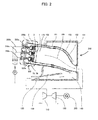
- Fig. 2 is a schematic diagram showing an example of a gas turbine combustor to which the cluster-type burner of the first embodiment is applied.
- Fig. 2 shows entire gas turbine equipment for a power generator plant, inclusive of the combustor.
- High-pressure air 120 that has been introduced from an air compressor 110 is further introduced from a diffuser 130 of the combustor into a casing 140 present inside a casing 131, and then flows into a clearance between a transition piece 150 and a transition piece flow sleeve 152. After this, the air 120 flows through a clearance between a liner 160 and a liner flow sleeve 161 disposed concentrically with an outer surface of the liner, then reverses the flow, and mixes with the fuel injected from the burner section 300, thereby to form a flame inside the combustion chamber 170 internal to the liner and become a high-temperature high-pressure combustion gas 180.
- the burner section 300 a multi-cluster-type burner equipped with seven cluster-type burners having the cluster-type burner construction shown in Figs. 1A and 1B , includes a central cluster-type burner 300a and six cluster-type burners, 300b to 300g, that are concentrically arranged at equal intervals around the central cluster-type burner 300a (of the six cluster-type burners, only the uppermost cluster-type burner 300b and the second lowermost cluster-type burner 300e are shown in Fig. 2 ).
- the cluster-type burners 300a to 300g are supplied with fuel from respective fuel supply systems 260a to 260g (only the fuel supply systems 260a, 260b, 260e are shown in Fig. 2 ).
- fuel nozzles and premixing passages are shown in section in a concentric dual-array pattern.
- central and outer circumferential guide vanes are collectively shown as one guide vane, and an inner circumferential guide vane is omitted.
- Air that has flown from the fuel supply systems 260a-260g into the burner section 300 is mixed, in the premixing passages 3 (see Fig. 1A ) of the premixing plate 4, with the fuel injected from the fuel nozzles 2 (see Sigs. 1A and 1B) of the cluster-type burners 300a-300g, and then supplied to the combustion chamber 170.
- the combustion gas 180 that has thus been generated in the combustor is introduced from the transition piece 150 into a turbine 190.
- a certain amount of work arises from adiabatic expansion of the high-temperature high-pressure combustion gas 180.
- the turbine 190 converts the generated amount of work into rotational force of a shaft and obtains an output from a generator 200. This rotational force of the shaft can also be used to rotate another compressor instead of the generator 200 and thus to operate the gas turbine as a motive power source for compressing fluids.
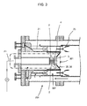
- Fig. 3 is a schematic diagram showing another example of a gas turbine combustor to which the cluster-type burner of the first embodiment is applied.
- the combustor 251 uses a central pilot burner as the cluster-type burner 301 of the present embodiment, and an outer circumferential main burner as a general premixing burner 302 that includes a fuel nozzle 21 and forms a premixed flame 23.
- Fuel is supplied from a fuel supply system 261 to the cluster-type burner 301.
- fuel nozzles and premixing passages are also shown in section in a concentric dual-array pattern.
- central and outer circumferential guide vanes are collectively shown as one guide vane, and an inner circumferential guide vane is omitted.
- disposing the guide vanes enables a desired amount of combustion air to be conducted to the fuel injecting ports of each fuel nozzle and the desired fuel-air ratio to be stably obtained for each circumferential array of fuel nozzles.
- This in turn enables the fuel supply system to be simplified by either integrating the fuel supply systems 260a-260g (see Fig. 2 ) into one, or adopting the integrated fuel supply system 261 (see Fig. 3 ), for each cluster-type burner.
- the above disposition of the guide vanes also enables stability of a combustion state to be improved and hence, NOx emissions to be reduced because of premixing.
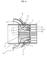
- FIG. 4 is a sectional view similar to that of Fig. 1A , showing construction of a burner section of a gas turbine combustor according to the second embodiment.
- the burner section of the combustor according to the second embodiment includes a compact guide vane 37 at an outer circumferential side, instead of the outer circumferential guide vane 36 in Fig. 1A .
- An extension of the outer circumferential guide vane 37 (a second guide vane) that extends toward an upstream side is shorter than that of a central guide vane 35 (a first guide vane), so that the extension in the upstream side is also shorter than that of the outer circumferential guide vane 36 in Fig. 1A and the outer circumferential guide vane 37 is reduced in outside diameter as well.
- FIG. 5 is a sectional view similar to that of Fig. 1A , showing construction of a burner section of a gas turbine combustor according to the third embodiment.
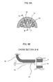
- FIG. 6A is an external view equivalent to an upper half of the central support rod 5 and central guide vane 35 of the burner section in Fig. 1B .
- Fig. 6B is an external view of cross section B-B in Fig. 6A , taken from a direction of arrows.
- the present embodiment is characterized by the fact that in addition to the guide vane 35, a protruding vane 63 for rectifying an axial flow of combustion air is disposed on an inner circumferential surface of the guide vane 35, near a downstream end of this guide vane.
- the protruding vane 63 as shown, is a triangular vane whose vertex as viewed in transverse section faces toward a central axis of the vane.
- the triangular vane 63 in plurality and spacing the plurality of triangular vanes 63 in a circumferential direction and in parallel with respect to the axial direction allows the axial flow of the combustion air to be rectified and guided to the fuel injecting ports of the fuel nozzles 2 at which the respective flow passages 7 are positioned. While an example of disposing the protruding vane 63 on the inner circumferential surface of the guide vane 35 is shown in Figs. 6A and 6B , if a similar protruding vane is disposed on an inner circumferential surface of the central guide vane 36, near a downstream end of the vane, this enables substantially the same advantageous effects to be obtained. Such a protruding vane may be further disposed on outer circumferential surfaces of the guide vanes 34, 35, 36, near downstream ends of these vanes.
- the premixing passage 3 is inclined with respect to the axial direction to impart a swirling force to the mixture flow of the fuel and air
- mounting the protruding vane 63 at an appropriate angle with respect to the axial direction according to the particular inclination of the premixing passage 3 will enable a swirling angle to be imparted to the combustion air before it enters the premixing passage 3, and will thus enable the air to be even more efficiently mixed with the fuel axially injected from the fuel nozzles 2.
- the fuel nozzles have been disposed in three arrays concentrically and the inner circumferential guide vane 34, the central guide vane 35, and the outer circumferential guide vane 36 have been provided to form one airflow passage for each of the arrays by division.
- the number of airflow passages formed by division does not always need to match the number of fuel nozzle arrays.
- the number of concentric arrays of the fuel nozzles may be other than three.
- the number of arrays can be two or four, for example. In this case, it will be necessary at least to arrange an appropriate number of guide vanes according to the particular number of concentric arrays of the fuel nozzles and form one airflow passage for each of the arrays by division.
Landscapes
- Engineering & Computer Science (AREA)
- Chemical & Material Sciences (AREA)
- Combustion & Propulsion (AREA)
- Mechanical Engineering (AREA)
- General Engineering & Computer Science (AREA)
Abstract
Description
- The present invention relates generally to gas turbine combustor. More particularly, the invention is directed to gas turbine combustor including a cluster-type burner that injects a fuel from a plurality of fuel nozzles into a plurality of premixing passages formed in a premixing plate, then after mixing in the premixing passages the injected fuel and a flow of air guided to fuel injecting ports of the fuel nozzles, supplies the mixed fuel and air to a combustion chamber, and burns the mixed fuel and air therein.
- In gas turbine combustor, emissions of nitrogen oxides (NOx), which are air pollutants, can be suppressed to a low level by using a premixed combustion scheme that forms a flame in a combustion chamber after the fuel and air have been premixed. Among known burners of the premixed combustion scheme are those of a coaxial jet flow combustion scheme in which a fuel and air are supplied as coaxial jet flows to a combustion chamber and burned therein. These burners are hereinafter referred to as cluster-type burners, an example of which is described in
JP-2003-148734-A - To adopt a cluster-type burner, it is structurally necessary to arrange fuel nozzles concentrically in several arrays in a circumferential direction. Therefore, flow passage resistance of combustion air is increased as the combustion air flows from an outer circumferential region into an inner circumferential region, and this increases the amount of combustion air flowing into the outer circumferential fuel nozzles of less resistance and reduces the amount of air flowing into the inner circumferential fuel nozzles. The reduction in the amount of air in the inner circumferential fuel nozzles will increase a mixture ratio of the fuel and air (this mixture ratio is hereinafter referred to as the fuel-air ratio), thus causing an increase in combustion temperature and hence an increase in NOx as well. In addition, a problem of reduced combustion stability will arise from instability of a flow rate of the air in certain positions.
- For these reasons, it is common to control the fuel-air ratio by dividing the fuel supply system and setting appropriate supply rates of the fuel for the inner circumferential and outer circumferential fuel nozzles. The resulting increase in the number of fuel systems poses further problems such as an increased number of parts, increased manufacturing costs, and complicated maintenance.
- The present invention has been created with the above problems in mind, and an object of the invention is to provide a gas turbine combustor including a cluster-type burner with a plurality of fuel nozzles arranged therein, the combustor being adapted to stabilize a combustion state by supplying a desired flow rate of air to inner circumferential and outer circumferential fuel nozzle sections.
- In order to attain the above object, an aspect of the present invention is a gas turbine combustor including a cluster-type burner with a plurality of fuel nozzles arranged therein, the combustor further including at least one guide vane formed to divide an airflow passage extending from an upstream side of the fuel nozzles to fuel injecting ports of the fuel nozzles, into a plurality of flow passages and rectify and guide a flow of air in each of the flow passages.
- This suppresses any differences in the amount of air at the fuel injecting ports of the inner circumferential and outer circumferential fuel nozzles due to pressure variations in the combustor or flow passage resistance of the fuel nozzles themselves. A desired amount of air can therefore be supplied to the fuel injecting ports of the fuel nozzles. The above vane arrangement is also effective for rectifying a flow of air in an axial direction of the burner section, and thus enables combustion stability to be enhanced. In addition, since the combustion state can be stabilized even without dividing a fuel supply system, a simplified fuel supply system can be formed by integrating fuel supply systems into one.
- In the present invention, the desired amount of combustion air can be guided to the fuel injecting ports of the fuel nozzles and a desired fuel-air ratio can be stably obtained for each of the circumferential fuel nozzle arrays. This enhances the stability of the combustion state and enables NOx emissions to be reduced. Additionally a simplified fuel supply system can be formed by integrating fuel supply systems into one.
-
-
Fig. 1A is a sectional view that shows construction of a burner section of a gas turbine combustor according to a first embodiment of the present invention. -
Fig. 1B is an external view of cross section A-A inFig. 1A , taken from a direction of arrows. -
Fig. 2 is a schematic diagram showing an example of a gas turbine combustor to which the cluster-type burner of the first embodiment is applied. -
Fig. 3 is a schematic diagram showing another example of a gas turbine combustor to which the cluster-type burner of the first embodiment is applied. -
Fig. 4 is a sectional view that shows construction of a burner section of a gas turbine combustor according to a second embodiment of the present invention. -
Fig. 5 is a sectional view that shows construction of a burner section of a gas turbine combustor according to a third embodiment of the present invention. -
Fig. 6A is a sectional view that shows construction of a burner section of a gas turbine combustor according to a fourth embodiment of the present invention. -
Fig. 6B is an external view of cross section B-B inFig. 6A , taken from a direction of arrows. -
Fig. 7 is a diagram that shows trends in air flow rate changes on a comparative basis between the present invention and a conventional burner structure. - Hereunder, embodiments of the present invention will be described with reference to the accompanying drawings.
-
Figs. 1A and1B show construction of a burner section of a gas turbine combustor according to a first embodiment of the present invention,Fig. 1A being a sectional view andFig. 1B being an external view of cross section A-A inFig. 1A , taken from a direction of arrows. - Referring to
Figs. 1A and1B , the burner section of the gas turbine combustor is a cluster-type burner that includes a plurality offuel nozzles 2 and apremixing plate 4 in which are formed a plurality ofpremixing passages 3 each positioned at a downstream side of one of thefuel nozzles 2. The plurality offuel nozzles 2 are connected to an end face of afuel nozzle header 1, and thepremixing plate 4 is connected to the end face of afuel nozzle header 1 via acentral support rod 5 and a plurality of outercircumferential support rods 6. The plurality offuel nozzles 2 include three arrays of fuel nozzles, namely an innercircumferential fuel nozzle 2a, acentral fuel nozzle 2b, and an outercircumferential fuel nozzle 2c, that are arranged in concentric form and are equally spaced in a circumferential direction of the burner section. In association with the innercircumferential fuel nozzle 2a, thecentral fuel nozzle 2b, and the outercircumferential fuel nozzle 2c, the plurality ofpremixing passages 3 include an innercircumferential premixing passage 3a, centralpremixing passage 3b, and outercircumferential premixing passage 3c, respectively, that are spacedly arranged at equal intervals in the circumferential direction of the burner section. Thepremixing passages 3 are formed so that preferably at least one part of thepremixing passages 3 inclines at a central axis thereof relative to an axial direction of the burner section and is constructed to promote mixing of a fuel and air by imparting an axial swirling force around a combustion chamber to a mixture flow of the fuel and air within thepremixing passage 3. - In addition, the burner section of the gas turbine combustor includes, as its characteristic elements, an inner
circumferential guide vane 34, acentral guide vane 35, and an outercircumferential guide vane 36. These guide vanes divide an airflow passage extending from an upstream side of the plurality offuel nozzles 2 to fuel injecting ports of thefuel nozzles 2, into a plurality offlow passages 7, and rectify and guide a flow of air in each of the flow passages. - The inner
circumferential guide vane 34 is constructed so as to pass through thecentral support rod 5 and thefuel nozzles 2, and is supported by thecentral support rod 5. In addition, the inner circumferential guide vane 34 abuts upon the end face of thefuel nozzle header 1 and is fixed thereto by welding or the like. Thecentral guide vane 35 and the outercircumferential guide vane 36 are constructed so as to pass through the outercircumferential support rods 6, and are fixed to and retained by the outercircumferential support rods 6 by means of welding or the like. - The plurality of
airflow passages 7 obtained from the division by theguide vanes circumferential airflow passage 7a formed by the division by the innercircumferential guide vane 34 and thecentral guide vane 35, acentral airflow passage 7b formed by the division by thecentral guide vane 35 and the outercircumferential guide vane 36, and an outercircumferential airflow passage 7c formed by the division by the outercircumferential guide vane 36. The fuel injecting ports of thefuel nozzle 2a are positioned at a terminal portion of the innercircumferential airflow passage 7a, the fuel injecting ports of thefuel nozzle 2b are positioned at a terminal portion of thecentral airflow passage 7b, and the fuel injecting ports of thefuel nozzle 2c are positioned at a terminal portion of the outercircumferential airflow passage 7c. - In this way, the airflow passage in the burner section is divided into the plurality of
airflow passages fuel nozzles circumferential guide vane 34, thecentral guide vane 35, and the outercircumferential guide vane 36, and the plurality of airflow passages guide the combustion air to the respective fuel injecting ports of thecorresponding fuel nozzles 2. - Sizes and shapes of the
guide vanes airflow passages guide vanes relevant fuel nozzle - In general, a diffusion flame formed by directly injecting a fuel into a combustion chamber has high flame stability because of a flame temperature higher than that of a premixed flame formed after the fuel and air have been mixed in advance. In contrast to this, the cluster-type burner as described in
JP-2003-148734-A - One of the reasons for the low flame stability in a cluster-type burner is that a change in the amount of air due to a change in an internal pressure of the combustor causes unstable mixing between the fuel from each fuel nozzle and the air. In addition, cluster-type burners need to have a large number of fuel nozzles in a limited space and hence to have multi-array nozzle construction, so that as shown in
Fig. 7 , outer circumferential fuel nozzles become flow passage resistance to develop a difference in a flow rate of combustion air between an outer circumferential side and an inner circumferential side, thereby reduce the flow rate of the combustion air flowing into the fuel nozzles positioned at the inner circumferential side, and reduce a velocity of the air as well. Consequently, the burner construction may further cause a change in the amount of air itself and this change may render a designed fuel-air ratio unobtainable. Moreover, if the amount of air is too small, an increase in NOx emissions due to an increase in fuel-air ratio is likely, and if the amount of air is too large, this is likely to deteriorate ignitability and result in unstable combustion. - The present embodiment shown in
Figs. 1A and1B includes theguide vanes circumferential fuel nozzle 2a or thecentral fuel nozzle 2b. Thus, in the burner section of the combustor with the three arrays offuel nozzles Figs. 1A and1B , the flow rate is governed in the innercircumferential airflow passage 7a formed by the innercircumferential guide vane 34 and thecentral guide vane 35, thecombustion air 41 flows in a rectified condition through the innercircumferential airflow passage 7a and after this, is guided to the innercircumferential premixing passage 3a. In the innercircumferential premixing passage 3a, innercircumferential combustion air 41 for is mixed with the fuel injected from the innercircumferential fuel nozzle 2a, and then this mixture passes through the innercircumferential premixing passage 3a and becomes ignited and burned in the combustion chamber. - Similarly, a defined flow rate of
central combustion air 42 flows in a rectified condition through thecentral airflow passage 7b formed by thecentral guide vane 35 and the outercircumferential guide vane 36, and is guided to the innercircumferential premixing passage 3b. At the same time, a defined flow rate of outercircumferential combustion air 43 flows in a rectified condition through the outercircumferential airflow passage 7c formed in an outer circumferential region of the outercircumferential guide vane 36, and is guided to the outercircumferential premixing passage 3c. Thecentral combustion air 42 and outercircumferential combustion air 43 that have thus been guided to the respective guide vanes are mixed with the fuel in the central and outercircumferential premixing passages - Thus the present embodiment suppresses any differences in the amount of air at the fuel injecting ports of the inner circumferential and outer circumferential fuel nozzles due to pressure variations in the combustor or flow passage resistance of the fuel nozzles themselves, thus enabling the desired amount of air to be supplied to the fuel injecting ports of the fuel nozzles. The embodiment is also effective for rectifying the flow of air in the axial direction of the burner section, and hence enables combustion stability to be enhanced.
-
Fig. 2 is a schematic diagram showing an example of a gas turbine combustor to which the cluster-type burner of the first embodiment is applied.Fig. 2 shows entire gas turbine equipment for a power generator plant, inclusive of the combustor. - High-
pressure air 120 that has been introduced from anair compressor 110 is further introduced from adiffuser 130 of the combustor into acasing 140 present inside acasing 131, and then flows into a clearance between atransition piece 150 and a transitionpiece flow sleeve 152. After this, theair 120 flows through a clearance between aliner 160 and aliner flow sleeve 161 disposed concentrically with an outer surface of the liner, then reverses the flow, and mixes with the fuel injected from theburner section 300, thereby to form a flame inside thecombustion chamber 170 internal to the liner and become a high-temperature high-pressure combustion gas 180. - The
burner section 300, a multi-cluster-type burner equipped with seven cluster-type burners having the cluster-type burner construction shown inFigs. 1A and1B , includes a central cluster-type burner 300a and six cluster-type burners, 300b to 300g, that are concentrically arranged at equal intervals around the central cluster-type burner 300a (of the six cluster-type burners, only the uppermost cluster-type burner 300b and the second lowermost cluster-type burner 300e are shown inFig. 2 ). The cluster-type burners 300a to 300g are supplied with fuel from respectivefuel supply systems 260a to 260g (only thefuel supply systems Fig. 2 ). For the sake of illustrative convenience inFig. 2 , fuel nozzles and premixing passages are shown in section in a concentric dual-array pattern. Likewise, central and outer circumferential guide vanes are collectively shown as one guide vane, and an inner circumferential guide vane is omitted. Air that has flown from thefuel supply systems 260a-260g into theburner section 300 is mixed, in the premixing passages 3 (seeFig. 1A ) of thepremixing plate 4, with the fuel injected from the fuel nozzles 2 (see Sigs. 1A and 1B) of the cluster-type burners 300a-300g, and then supplied to thecombustion chamber 170. - The
combustion gas 180 that has thus been generated in the combustor is introduced from thetransition piece 150 into aturbine 190. In theturbine 190, a certain amount of work arises from adiabatic expansion of the high-temperature high-pressure combustion gas 180. Theturbine 190 converts the generated amount of work into rotational force of a shaft and obtains an output from agenerator 200. This rotational force of the shaft can also be used to rotate another compressor instead of thegenerator 200 and thus to operate the gas turbine as a motive power source for compressing fluids. -
Fig. 3 is a schematic diagram showing another example of a gas turbine combustor to which the cluster-type burner of the first embodiment is applied. In this example of application, thecombustor 251 uses a central pilot burner as the cluster-type burner 301 of the present embodiment, and an outer circumferential main burner as ageneral premixing burner 302 that includes afuel nozzle 21 and forms apremixed flame 23. Fuel is supplied from afuel supply system 261 to the cluster-type burner 301. For the sake of illustrative convenience inFig. 3 , fuel nozzles and premixing passages are also shown in section in a concentric dual-array pattern. Likewise, central and outer circumferential guide vanes are collectively shown as one guide vane, and an inner circumferential guide vane is omitted. - In the
combustors Figs. 2 and3 , even without dividing the fuel supply system into a plurality of systems for the cluster-type burners 300a-300g or 301, disposing the guide vanes enables a desired amount of combustion air to be conducted to the fuel injecting ports of each fuel nozzle and the desired fuel-air ratio to be stably obtained for each circumferential array of fuel nozzles. This in turn enables the fuel supply system to be simplified by either integrating thefuel supply systems 260a-260g (seeFig. 2 ) into one, or adopting the integrated fuel supply system 261 (seeFig. 3 ), for each cluster-type burner. The above disposition of the guide vanes also enables stability of a combustion state to be improved and hence, NOx emissions to be reduced because of premixing. - A second embodiment of the present invention is described below using
Fig. 4. Fig. 4 is a sectional view similar to that ofFig. 1A , showing construction of a burner section of a gas turbine combustor according to the second embodiment. - Referring to
Fig. 4 , the burner section of the combustor according to the second embodiment includes acompact guide vane 37 at an outer circumferential side, instead of the outercircumferential guide vane 36 inFig. 1A . An extension of the outer circumferential guide vane 37 (a second guide vane) that extends toward an upstream side is shorter than that of a central guide vane 35 (a first guide vane), so that the extension in the upstream side is also shorter than that of the outercircumferential guide vane 36 inFig. 1A and the outercircumferential guide vane 37 is reduced in outside diameter as well. These geometric characteristics of the burner section make a radial size of the burner suppressible and thus enable an installation space requirement to be saved. Only the outercircumferential fuel nozzle 2c acts as flow passage resistance to the air that flows into the fuel injecting ports of thecentral fuel nozzle 2b, and the flow passage resistance is low relative to that of the innercircumferential fuel nozzle 2a. Therefore, substantially the same advantageous effects as in the embodiment ofFig. 1A can be obtained by providing a clearance greater than in the first embodiment ofFig. 1A , between thecentral guide vane 35 and the compact outercircumferential guide vane 37, and controlling the flow rate of the air in the outer circumferential and central regions. - A third embodiment of the present invention is described below using
Fig. 5. Fig. 5 is a sectional view similar to that ofFig. 1A , showing construction of a burner section of a gas turbine combustor according to the third embodiment. - In the present embodiment, when an inner
circumferential guide vane 51, acentral guide vane 52, and an outercircumferential guide vane 53 are viewed in axial section, these guide vanes are of a simple linear shape, not such a curvilinear one as inFig. 1 . Accordingly, frictional resistance of the air which flows along theguide vanes - A fourth embodiment of the present invention is described below using
Figs. 6A and 6B. Fig. 6A is an external view equivalent to an upper half of thecentral support rod 5 andcentral guide vane 35 of the burner section inFig. 1B .Fig. 6B is an external view of cross section B-B inFig. 6A , taken from a direction of arrows. - The present embodiment is characterized by the fact that in addition to the
guide vane 35, a protrudingvane 63 for rectifying an axial flow of combustion air is disposed on an inner circumferential surface of theguide vane 35, near a downstream end of this guide vane. The protrudingvane 63, as shown, is a triangular vane whose vertex as viewed in transverse section faces toward a central axis of the vane. Mounting thetriangular vane 63 in plurality and spacing the plurality oftriangular vanes 63 in a circumferential direction and in parallel with respect to the axial direction allows the axial flow of the combustion air to be rectified and guided to the fuel injecting ports of thefuel nozzles 2 at which therespective flow passages 7 are positioned. While an example of disposing the protrudingvane 63 on the inner circumferential surface of theguide vane 35 is shown inFigs. 6A and 6B , if a similar protruding vane is disposed on an inner circumferential surface of thecentral guide vane 36, near a downstream end of the vane, this enables substantially the same advantageous effects to be obtained. Such a protruding vane may be further disposed on outer circumferential surfaces of theguide vanes - In addition, if the
premixing passage 3 is inclined with respect to the axial direction to impart a swirling force to the mixture flow of the fuel and air, mounting the protrudingvane 63 at an appropriate angle with respect to the axial direction according to the particular inclination of thepremixing passage 3 will enable a swirling angle to be imparted to the combustion air before it enters thepremixing passage 3, and will thus enable the air to be even more efficiently mixed with the fuel axially injected from thefuel nozzles 2. - In the above embodiments, the fuel nozzles have been disposed in three arrays concentrically and the inner
circumferential guide vane 34, thecentral guide vane 35, and the outercircumferential guide vane 36 have been provided to form one airflow passage for each of the arrays by division. The number of airflow passages formed by division, however, does not always need to match the number of fuel nozzle arrays. Alternatively, the number of concentric arrays of the fuel nozzles may be other than three. The number of arrays can be two or four, for example. In this case, it will be necessary at least to arrange an appropriate number of guide vanes according to the particular number of concentric arrays of the fuel nozzles and form one airflow passage for each of the arrays by division. - Features, components and specific details of the structures of the above-described embodiments may be exchanged or combined to form further embodiments optimized for the respective application. As far as those modifications are apparent for an expert skilled in the art they shall be disclosed implicitly by the above description without specifying explicitly every possible combination.
Claims (6)
- A gas turbine combustor comprising:a plurality of fuel nozzles (2);a premixing plate (4) in which are formed a plurality of premixing passages (3) each positioned at a downstream side of the corresponding one of the fuel nozzles (2), injected fuel from the plurality of fuel nozzles being mixed with air in the premixing passages (3) before being supplied to a combustion chamber (170) and burnt therein; anda plurality of guide vanes (34, 35, 36) formed to divide into a plurality of flow passages (7) an airflow passage extending from an upstream side of the plurality of fuel nozzles (2) to fuel injecting ports of the fuel nozzles, the plurality of guide vanes rectifying a flow of air in each of the flow passages (7) and guiding the flow of air to the fuel injecting ports of the fuel nozzles (2).
- The gas turbine combustor according to claim 1, wherein:sizes and shapes of the plurality of guide vanes (34, 35, 36) are determined so that a mixture ratio of air and the fuel injected from the fuel nozzles (2) takes a predetermined value in each of the airflow passages formed by the guide vanes.
- The gas turbine combustor according to claim 1 or 2, wherein:the plurality of guide vanes (34, 35, 36) comprise a first guide vane and a second guide vane,the first guide vane guiding air to only the fuel injecting ports of the fuel nozzle positioned at an inner circumferential side,the second guide vane guiding air to the fuel injecting ports of the fuel nozzle (3) positioned at an outer circumferential side,an extension of the second guide vane that extends toward an upstream side is shorter than an extension of the first guide vane, the second guide vane being reduced in outside diameter.
- The gas turbine combustor according to claim 1 or 2, wherein:the plurality of guide vanes are configured to each have a linear shape when viewed in axial section, thereby reducing frictional resistance of the air which flows along the guide vanes.
- The gas turbine combustor according to claim 1 or 2, wherein:a plurality of protruding vanes (34, 35, 36) spaced from each other in a circumferential direction are disposed on an inner circumferential surface of at least one of the plurality of guide vanes near a downstream end of the guide vane, andthe protruding vanes rectify a property of the air flowing along the guide vane and guide the rectified flow of the air to the fuel injecting ports of the fuel nozzles (2) positioned in the respective flow passages.
- The gas turbine combustor according to claim 5, wherein:at least one of the plurality of premixing passages (3) is inclined relative to an axial direction, and the protruding vanes are mounted to be inclined relative to the axial direction according to the inclination of the premixing passage, thereby imparting a swirling angle to combustion air before the air enters the premixing passage.
Applications Claiming Priority (1)
| Application Number | Priority Date | Filing Date | Title |
|---|---|---|---|
| JP2013237305A JP6228434B2 (en) | 2013-11-15 | 2013-11-15 | Gas turbine combustor |
Publications (2)
| Publication Number | Publication Date |
|---|---|
| EP2873922A1 true EP2873922A1 (en) | 2015-05-20 |
| EP2873922B1 EP2873922B1 (en) | 2021-04-28 |
Family
ID=51900253
Family Applications (1)
| Application Number | Title | Priority Date | Filing Date |
|---|---|---|---|
| EP14193129.5A Active EP2873922B1 (en) | 2013-11-15 | 2014-11-14 | Gas turbine combustor |
Country Status (4)
| Country | Link |
|---|---|
| US (1) | US10125992B2 (en) |
| EP (1) | EP2873922B1 (en) |
| JP (1) | JP6228434B2 (en) |
| CN (1) | CN104654361B (en) |
Cited By (2)
| Publication number | Priority date | Publication date | Assignee | Title |
|---|---|---|---|---|
| CN105180212A (en) * | 2015-09-02 | 2015-12-23 | 中国人民解放军国防科学技术大学 | Combustion chamber of supersonic combustion ramjet engine |
| CN112902171A (en) * | 2021-02-03 | 2021-06-04 | 沈阳理工大学 | Double-rotation burner |
Families Citing this family (10)
| Publication number | Priority date | Publication date | Assignee | Title |
|---|---|---|---|---|
| US20170370589A1 (en) * | 2016-06-22 | 2017-12-28 | General Electric Company | Multi-tube late lean injector |
| CN107620983B (en) * | 2017-09-05 | 2023-04-25 | 中国联合重型燃气轮机技术有限公司 | Fuel nozzle |
| JP7149807B2 (en) | 2018-11-01 | 2022-10-07 | 三菱重工業株式会社 | gas turbine combustor |
| JP7112342B2 (en) * | 2019-01-25 | 2022-08-03 | 三菱重工業株式会社 | gas turbine combustor and gas turbine |
| CN111780112B (en) * | 2020-07-14 | 2022-06-21 | 江苏迈阳环保有限公司 | Injection mechanism for low-nitrogen combustor |
| KR102474179B1 (en) * | 2021-01-15 | 2022-12-06 | 두산에너빌리티 주식회사 | Combustor with multi-tube and gas turbine including same |
| CN113091095B (en) * | 2021-05-13 | 2023-05-23 | 中国联合重型燃气轮机技术有限公司 | Gas turbine combustor nozzle and method for premixing fuel and air in nozzle |
| CN113091094B (en) * | 2021-05-13 | 2023-05-23 | 中国联合重型燃气轮机技术有限公司 | Gas turbine combustor nozzle and method for premixing fuel and air in nozzle |
| CN116202104B (en) * | 2023-02-06 | 2024-05-07 | 中国科学院工程热物理研究所 | A gas turbine multi-nozzle array stabilization combustion chamber |
| CN120101180A (en) * | 2025-04-11 | 2025-06-06 | 中国联合重型燃气轮机技术有限公司 | A low-consistency blade guide combustion chamber device for a gas turbine fuel injection combination |
Citations (5)
| Publication number | Priority date | Publication date | Assignee | Title |
|---|---|---|---|---|
| JP2003148734A (en) | 2001-08-29 | 2003-05-21 | Hitachi Ltd | Gas turbine combustor and method of operating gas turbine combustor |
| EP1826485A2 (en) * | 2006-02-28 | 2007-08-29 | Hitachi, Ltd. | Burner, method of combustion with the burner, and method of modifying the burner |
| EP2527738A2 (en) * | 2011-05-24 | 2012-11-28 | General Electric Company | System and method for flow control in gas turbine engine |
| EP2551491A2 (en) * | 2011-07-29 | 2013-01-30 | General Electric Company | System for conditioning air flow into a multi-nozzle assembly |
| US20130139511A1 (en) * | 2011-03-16 | 2013-06-06 | Mitsubishi Heavy Industries, Ltd. | Gas turbine combustor and gas turbine |
Family Cites Families (7)
| Publication number | Priority date | Publication date | Assignee | Title |
|---|---|---|---|---|
| US5983642A (en) * | 1997-10-13 | 1999-11-16 | Siemens Westinghouse Power Corporation | Combustor with two stage primary fuel tube with concentric members and flow regulating |
| JP3364169B2 (en) * | 1999-06-09 | 2003-01-08 | 三菱重工業株式会社 | Gas turbine and its combustor |
| CN1242201C (en) * | 2001-07-10 | 2006-02-15 | 三菱重工业株式会社 | Premixing nozzle, burner and gas turbine |
| US6813889B2 (en) | 2001-08-29 | 2004-11-09 | Hitachi, Ltd. | Gas turbine combustor and operating method thereof |
| WO2006021543A1 (en) * | 2004-08-27 | 2006-03-02 | Alstom Technology Ltd | Mixer assembly |
| US20130180248A1 (en) * | 2012-01-18 | 2013-07-18 | Nishant Govindbhai Parsania | Combustor Nozzle/Premixer with Curved Sections |
| RU2015156419A (en) * | 2015-12-28 | 2017-07-04 | Дженерал Электрик Компани | The fuel injector assembly made with a flame stabilizer pre-mixed mixture |
-
2013
- 2013-11-15 JP JP2013237305A patent/JP6228434B2/en active Active
-
2014
- 2014-11-12 CN CN201410645902.0A patent/CN104654361B/en active Active
- 2014-11-13 US US14/540,123 patent/US10125992B2/en active Active
- 2014-11-14 EP EP14193129.5A patent/EP2873922B1/en active Active
Patent Citations (5)
| Publication number | Priority date | Publication date | Assignee | Title |
|---|---|---|---|---|
| JP2003148734A (en) | 2001-08-29 | 2003-05-21 | Hitachi Ltd | Gas turbine combustor and method of operating gas turbine combustor |
| EP1826485A2 (en) * | 2006-02-28 | 2007-08-29 | Hitachi, Ltd. | Burner, method of combustion with the burner, and method of modifying the burner |
| US20130139511A1 (en) * | 2011-03-16 | 2013-06-06 | Mitsubishi Heavy Industries, Ltd. | Gas turbine combustor and gas turbine |
| EP2527738A2 (en) * | 2011-05-24 | 2012-11-28 | General Electric Company | System and method for flow control in gas turbine engine |
| EP2551491A2 (en) * | 2011-07-29 | 2013-01-30 | General Electric Company | System for conditioning air flow into a multi-nozzle assembly |
Cited By (3)
| Publication number | Priority date | Publication date | Assignee | Title |
|---|---|---|---|---|
| CN105180212A (en) * | 2015-09-02 | 2015-12-23 | 中国人民解放军国防科学技术大学 | Combustion chamber of supersonic combustion ramjet engine |
| CN112902171A (en) * | 2021-02-03 | 2021-06-04 | 沈阳理工大学 | Double-rotation burner |
| CN112902171B (en) * | 2021-02-03 | 2023-07-11 | 沈阳理工大学 | A double-rotary burner |
Also Published As
| Publication number | Publication date |
|---|---|
| US20150135717A1 (en) | 2015-05-21 |
| EP2873922B1 (en) | 2021-04-28 |
| CN104654361B (en) | 2017-05-17 |
| CN104654361A (en) | 2015-05-27 |
| US10125992B2 (en) | 2018-11-13 |
| JP2015096794A (en) | 2015-05-21 |
| JP6228434B2 (en) | 2017-11-08 |
Similar Documents
| Publication | Publication Date | Title |
|---|---|---|
| EP2873922B1 (en) | Gas turbine combustor | |
| JP6335903B2 (en) | Flame sheet combustor dome | |
| JP6401463B2 (en) | System and method for air flow regulation at tube level | |
| CN105229379B (en) | Gas turbine combustor | |
| JP5412283B2 (en) | Combustion device | |
| EP1543272B1 (en) | Turbine engine fuel nozzle | |
| EP2796789B1 (en) | Can combustor for a can-annular combustor arrangement in a gas turbine | |
| US20190162413A1 (en) | Combustor liner for a gas turbine engine and an associated method thereof | |
| EP1985926A2 (en) | Combustion equipment and combustion method | |
| EP2620708B1 (en) | Gas turbine combustor and operating method thereof | |
| EP2837888A1 (en) | Sequential combustion with dilution gas mixer | |
| EP3102877B1 (en) | Combustor | |
| EP1826485A2 (en) | Burner, method of combustion with the burner, and method of modifying the burner | |
| CN102345879A (en) | Fuel nozzle and assembly and gas turbine comprising the same | |
| JP6723768B2 (en) | Burner assembly, combustor, and gas turbine | |
| JP3192055B2 (en) | Gas turbine combustor | |
| KR20240121266A (en) | Control method for gas turbine combustor and control device for gas turbine combustor | |
| JP2016023916A (en) | Gas turbine combustor | |
| US9410704B2 (en) | Annular strip micro-mixers for turbomachine combustor | |
| US20210116127A1 (en) | Gas Turbine Combuster |
Legal Events
| Date | Code | Title | Description |
|---|---|---|---|
| PUAI | Public reference made under article 153(3) epc to a published international application that has entered the european phase |
Free format text: ORIGINAL CODE: 0009012 |
|
| 17P | Request for examination filed |
Effective date: 20141219 |
|
| AK | Designated contracting states |
Kind code of ref document: A1 Designated state(s): AL AT BE BG CH CY CZ DE DK EE ES FI FR GB GR HR HU IE IS IT LI LT LU LV MC MK MT NL NO PL PT RO RS SE SI SK SM TR |
|
| AX | Request for extension of the european patent |
Extension state: BA ME |
|
| STAA | Information on the status of an ep patent application or granted ep patent |
Free format text: STATUS: EXAMINATION IS IN PROGRESS |
|
| 17Q | First examination report despatched |
Effective date: 20200527 |
|
| RAP1 | Party data changed (applicant data changed or rights of an application transferred) |
Owner name: MITSUBISHI POWER, LTD. |
|
| GRAP | Despatch of communication of intention to grant a patent |
Free format text: ORIGINAL CODE: EPIDOSNIGR1 |
|
| STAA | Information on the status of an ep patent application or granted ep patent |
Free format text: STATUS: GRANT OF PATENT IS INTENDED |
|
| INTG | Intention to grant announced |
Effective date: 20201119 |
|
| GRAS | Grant fee paid |
Free format text: ORIGINAL CODE: EPIDOSNIGR3 |
|
| GRAA | (expected) grant |
Free format text: ORIGINAL CODE: 0009210 |
|
| STAA | Information on the status of an ep patent application or granted ep patent |
Free format text: STATUS: THE PATENT HAS BEEN GRANTED |
|
| AK | Designated contracting states |
Kind code of ref document: B1 Designated state(s): AL AT BE BG CH CY CZ DE DK EE ES FI FR GB GR HR HU IE IS IT LI LT LU LV MC MK MT NL NO PL PT RO RS SE SI SK SM TR |
|
| REG | Reference to a national code |
Ref country code: GB Ref legal event code: FG4D |
|
| REG | Reference to a national code |
Ref country code: CH Ref legal event code: EP |
|
| REG | Reference to a national code |
Ref country code: AT Ref legal event code: REF Ref document number: 1387466 Country of ref document: AT Kind code of ref document: T Effective date: 20210515 |
|
| REG | Reference to a national code |
Ref country code: DE Ref legal event code: R096 Ref document number: 602014076948 Country of ref document: DE |
|
| REG | Reference to a national code |
Ref country code: IE Ref legal event code: FG4D |
|
| REG | Reference to a national code |
Ref country code: LT Ref legal event code: MG9D |
|
| REG | Reference to a national code |
Ref country code: AT Ref legal event code: MK05 Ref document number: 1387466 Country of ref document: AT Kind code of ref document: T Effective date: 20210428 |
|
| PG25 | Lapsed in a contracting state [announced via postgrant information from national office to epo] |
Ref country code: BG Free format text: LAPSE BECAUSE OF FAILURE TO SUBMIT A TRANSLATION OF THE DESCRIPTION OR TO PAY THE FEE WITHIN THE PRESCRIBED TIME-LIMIT Effective date: 20210728 Ref country code: AT Free format text: LAPSE BECAUSE OF FAILURE TO SUBMIT A TRANSLATION OF THE DESCRIPTION OR TO PAY THE FEE WITHIN THE PRESCRIBED TIME-LIMIT Effective date: 20210428 Ref country code: NL Free format text: LAPSE BECAUSE OF FAILURE TO SUBMIT A TRANSLATION OF THE DESCRIPTION OR TO PAY THE FEE WITHIN THE PRESCRIBED TIME-LIMIT Effective date: 20210428 Ref country code: LT Free format text: LAPSE BECAUSE OF FAILURE TO SUBMIT A TRANSLATION OF THE DESCRIPTION OR TO PAY THE FEE WITHIN THE PRESCRIBED TIME-LIMIT Effective date: 20210428 Ref country code: FI Free format text: LAPSE BECAUSE OF FAILURE TO SUBMIT A TRANSLATION OF THE DESCRIPTION OR TO PAY THE FEE WITHIN THE PRESCRIBED TIME-LIMIT Effective date: 20210428 Ref country code: HR Free format text: LAPSE BECAUSE OF FAILURE TO SUBMIT A TRANSLATION OF THE DESCRIPTION OR TO PAY THE FEE WITHIN THE PRESCRIBED TIME-LIMIT Effective date: 20210428 |
|
| PG25 | Lapsed in a contracting state [announced via postgrant information from national office to epo] |
Ref country code: IS Free format text: LAPSE BECAUSE OF FAILURE TO SUBMIT A TRANSLATION OF THE DESCRIPTION OR TO PAY THE FEE WITHIN THE PRESCRIBED TIME-LIMIT Effective date: 20210828 Ref country code: GR Free format text: LAPSE BECAUSE OF FAILURE TO SUBMIT A TRANSLATION OF THE DESCRIPTION OR TO PAY THE FEE WITHIN THE PRESCRIBED TIME-LIMIT Effective date: 20210729 Ref country code: LV Free format text: LAPSE BECAUSE OF FAILURE TO SUBMIT A TRANSLATION OF THE DESCRIPTION OR TO PAY THE FEE WITHIN THE PRESCRIBED TIME-LIMIT Effective date: 20210428 Ref country code: ES Free format text: LAPSE BECAUSE OF FAILURE TO SUBMIT A TRANSLATION OF THE DESCRIPTION OR TO PAY THE FEE WITHIN THE PRESCRIBED TIME-LIMIT Effective date: 20210428 Ref country code: PT Free format text: LAPSE BECAUSE OF FAILURE TO SUBMIT A TRANSLATION OF THE DESCRIPTION OR TO PAY THE FEE WITHIN THE PRESCRIBED TIME-LIMIT Effective date: 20210830 Ref country code: NO Free format text: LAPSE BECAUSE OF FAILURE TO SUBMIT A TRANSLATION OF THE DESCRIPTION OR TO PAY THE FEE WITHIN THE PRESCRIBED TIME-LIMIT Effective date: 20210728 Ref country code: PL Free format text: LAPSE BECAUSE OF FAILURE TO SUBMIT A TRANSLATION OF THE DESCRIPTION OR TO PAY THE FEE WITHIN THE PRESCRIBED TIME-LIMIT Effective date: 20210428 Ref country code: RS Free format text: LAPSE BECAUSE OF FAILURE TO SUBMIT A TRANSLATION OF THE DESCRIPTION OR TO PAY THE FEE WITHIN THE PRESCRIBED TIME-LIMIT Effective date: 20210428 Ref country code: SE Free format text: LAPSE BECAUSE OF FAILURE TO SUBMIT A TRANSLATION OF THE DESCRIPTION OR TO PAY THE FEE WITHIN THE PRESCRIBED TIME-LIMIT Effective date: 20210428 |
|
| REG | Reference to a national code |
Ref country code: NL Ref legal event code: MP Effective date: 20210428 |
|
| PG25 | Lapsed in a contracting state [announced via postgrant information from national office to epo] |
Ref country code: SK Free format text: LAPSE BECAUSE OF FAILURE TO SUBMIT A TRANSLATION OF THE DESCRIPTION OR TO PAY THE FEE WITHIN THE PRESCRIBED TIME-LIMIT Effective date: 20210428 Ref country code: SM Free format text: LAPSE BECAUSE OF FAILURE TO SUBMIT A TRANSLATION OF THE DESCRIPTION OR TO PAY THE FEE WITHIN THE PRESCRIBED TIME-LIMIT Effective date: 20210428 Ref country code: EE Free format text: LAPSE BECAUSE OF FAILURE TO SUBMIT A TRANSLATION OF THE DESCRIPTION OR TO PAY THE FEE WITHIN THE PRESCRIBED TIME-LIMIT Effective date: 20210428 Ref country code: CZ Free format text: LAPSE BECAUSE OF FAILURE TO SUBMIT A TRANSLATION OF THE DESCRIPTION OR TO PAY THE FEE WITHIN THE PRESCRIBED TIME-LIMIT Effective date: 20210428 Ref country code: DK Free format text: LAPSE BECAUSE OF FAILURE TO SUBMIT A TRANSLATION OF THE DESCRIPTION OR TO PAY THE FEE WITHIN THE PRESCRIBED TIME-LIMIT Effective date: 20210428 Ref country code: RO Free format text: LAPSE BECAUSE OF FAILURE TO SUBMIT A TRANSLATION OF THE DESCRIPTION OR TO PAY THE FEE WITHIN THE PRESCRIBED TIME-LIMIT Effective date: 20210428 |
|
| REG | Reference to a national code |
Ref country code: DE Ref legal event code: R097 Ref document number: 602014076948 Country of ref document: DE |
|
| PLBE | No opposition filed within time limit |
Free format text: ORIGINAL CODE: 0009261 |
|
| STAA | Information on the status of an ep patent application or granted ep patent |
Free format text: STATUS: NO OPPOSITION FILED WITHIN TIME LIMIT |
|
| 26N | No opposition filed |
Effective date: 20220131 |
|
| PG25 | Lapsed in a contracting state [announced via postgrant information from national office to epo] |
Ref country code: IS Free format text: LAPSE BECAUSE OF FAILURE TO SUBMIT A TRANSLATION OF THE DESCRIPTION OR TO PAY THE FEE WITHIN THE PRESCRIBED TIME-LIMIT Effective date: 20210828 Ref country code: AL Free format text: LAPSE BECAUSE OF FAILURE TO SUBMIT A TRANSLATION OF THE DESCRIPTION OR TO PAY THE FEE WITHIN THE PRESCRIBED TIME-LIMIT Effective date: 20210428 |
|
| PG25 | Lapsed in a contracting state [announced via postgrant information from national office to epo] |
Ref country code: MC Free format text: LAPSE BECAUSE OF FAILURE TO SUBMIT A TRANSLATION OF THE DESCRIPTION OR TO PAY THE FEE WITHIN THE PRESCRIBED TIME-LIMIT Effective date: 20210428 |
|
| REG | Reference to a national code |
Ref country code: CH Ref legal event code: PL |
|
| GBPC | Gb: european patent ceased through non-payment of renewal fee |
Effective date: 20211114 |
|
| PG25 | Lapsed in a contracting state [announced via postgrant information from national office to epo] |
Ref country code: LU Free format text: LAPSE BECAUSE OF NON-PAYMENT OF DUE FEES Effective date: 20211114 Ref country code: IT Free format text: LAPSE BECAUSE OF FAILURE TO SUBMIT A TRANSLATION OF THE DESCRIPTION OR TO PAY THE FEE WITHIN THE PRESCRIBED TIME-LIMIT Effective date: 20210428 Ref country code: BE Free format text: LAPSE BECAUSE OF NON-PAYMENT OF DUE FEES Effective date: 20211130 |
|
| REG | Reference to a national code |
Ref country code: BE Ref legal event code: MM Effective date: 20211130 |
|
| PG25 | Lapsed in a contracting state [announced via postgrant information from national office to epo] |
Ref country code: IE Free format text: LAPSE BECAUSE OF NON-PAYMENT OF DUE FEES Effective date: 20211114 Ref country code: GB Free format text: LAPSE BECAUSE OF NON-PAYMENT OF DUE FEES Effective date: 20211114 |
|
| PG25 | Lapsed in a contracting state [announced via postgrant information from national office to epo] |
Ref country code: FR Free format text: LAPSE BECAUSE OF NON-PAYMENT OF DUE FEES Effective date: 20211130 |
|
| PG25 | Lapsed in a contracting state [announced via postgrant information from national office to epo] |
Ref country code: HU Free format text: LAPSE BECAUSE OF FAILURE TO SUBMIT A TRANSLATION OF THE DESCRIPTION OR TO PAY THE FEE WITHIN THE PRESCRIBED TIME-LIMIT; INVALID AB INITIO Effective date: 20141114 |
|
| PG25 | Lapsed in a contracting state [announced via postgrant information from national office to epo] |
Ref country code: CY Free format text: LAPSE BECAUSE OF FAILURE TO SUBMIT A TRANSLATION OF THE DESCRIPTION OR TO PAY THE FEE WITHIN THE PRESCRIBED TIME-LIMIT Effective date: 20210428 |
|
| PG25 | Lapsed in a contracting state [announced via postgrant information from national office to epo] |
Ref country code: LI Free format text: LAPSE BECAUSE OF NON-PAYMENT OF DUE FEES Effective date: 20220630 Ref country code: CH Free format text: LAPSE BECAUSE OF NON-PAYMENT OF DUE FEES Effective date: 20220630 |
|
| PG25 | Lapsed in a contracting state [announced via postgrant information from national office to epo] |
Ref country code: MK Free format text: LAPSE BECAUSE OF FAILURE TO SUBMIT A TRANSLATION OF THE DESCRIPTION OR TO PAY THE FEE WITHIN THE PRESCRIBED TIME-LIMIT Effective date: 20210428 |
|
| PG25 | Lapsed in a contracting state [announced via postgrant information from national office to epo] |
Ref country code: MT Free format text: LAPSE BECAUSE OF FAILURE TO SUBMIT A TRANSLATION OF THE DESCRIPTION OR TO PAY THE FEE WITHIN THE PRESCRIBED TIME-LIMIT Effective date: 20210428 |
|
| PG25 | Lapsed in a contracting state [announced via postgrant information from national office to epo] |
Ref country code: TR Free format text: LAPSE BECAUSE OF FAILURE TO SUBMIT A TRANSLATION OF THE DESCRIPTION OR TO PAY THE FEE WITHIN THE PRESCRIBED TIME-LIMIT Effective date: 20210428 |
|
| PGFP | Annual fee paid to national office [announced via postgrant information from national office to epo] |
Ref country code: DE Payment date: 20250930 Year of fee payment: 12 |