EP2873613A1 - Counter-rotating rotor system with static mast - Google Patents
Counter-rotating rotor system with static mast Download PDFInfo
- Publication number
- EP2873613A1 EP2873613A1 EP20140191856 EP14191856A EP2873613A1 EP 2873613 A1 EP2873613 A1 EP 2873613A1 EP 20140191856 EP20140191856 EP 20140191856 EP 14191856 A EP14191856 A EP 14191856A EP 2873613 A1 EP2873613 A1 EP 2873613A1
- Authority
- EP
- European Patent Office
- Prior art keywords
- rotor
- rotor assembly
- assembly
- quill shaft
- static mast
- Prior art date
- Legal status (The legal status is an assumption and is not a legal conclusion. Google has not performed a legal analysis and makes no representation as to the accuracy of the status listed.)
- Granted
Links
- 230000003068 static effect Effects 0.000 title claims abstract description 47
- 230000009977 dual effect Effects 0.000 claims abstract description 12
- 244000309464 bull Species 0.000 description 3
- 230000004075 alteration Effects 0.000 description 1
- 230000000712 assembly Effects 0.000 description 1
- 238000000429 assembly Methods 0.000 description 1
- 238000009434 installation Methods 0.000 description 1
- 239000007787 solid Substances 0.000 description 1
- 238000006467 substitution reaction Methods 0.000 description 1
Images

Classifications
-
- B—PERFORMING OPERATIONS; TRANSPORTING
- B64—AIRCRAFT; AVIATION; COSMONAUTICS
- B64C—AEROPLANES; HELICOPTERS
- B64C27/00—Rotorcraft; Rotors peculiar thereto
- B64C27/04—Helicopters
- B64C27/08—Helicopters with two or more rotors
- B64C27/10—Helicopters with two or more rotors arranged coaxially
-
- B—PERFORMING OPERATIONS; TRANSPORTING
- B64—AIRCRAFT; AVIATION; COSMONAUTICS
- B64C—AEROPLANES; HELICOPTERS
- B64C27/00—Rotorcraft; Rotors peculiar thereto
- B64C27/54—Mechanisms for controlling blade adjustment or movement relative to rotor head, e.g. lag-lead movement
- B64C27/58—Transmitting means, e.g. interrelated with initiating means or means acting on blades
- B64C27/59—Transmitting means, e.g. interrelated with initiating means or means acting on blades mechanical
Definitions
- the subject matter disclosed herein relates to the art of rotary wing aircraft and, more specifically, to coaxial multi-rotor systems for rotary wing aircraft.
- rotary power is transmitted from an engine through a gearbox into the rotor system.
- the gearbox transfers power to a lower rotor shaft to drive a lower rotor assembly and to an upper rotor shaft coaxial with the lower rotor shaft to drive the upper rotor assembly.
- the systems typically include several sets of bearings between the upper rotor shaft and lower rotor shaft to transfer loads between the shafts.
- the bearings and controls for the upper rotor assembly drive an increased diameter for the upper rotor shaft, and thus the lower rotor shaft, which increases drag during operation.
- many coaxial rotor systems include an aerodynamic fairing positioned between the upper rotor assembly and the lower rotor assembly.
- Typical systems attach to the upper and lower rotor shafts, and include a significant derotation mechanism to prevent the fairing from rotating, and to keep the fairing oriented in a selected direction.
- a coaxial, dual rotor system includes a first rotor assembly positioned at a rotor axis.
- a first rotor quill shaft is operably connected to the first rotor assembly at the rotor axis to drive rotation of the first rotor assembly about the rotor axis.
- a nonrotating static mast extends along the rotor axis inside of the first rotor quill shaft.
- a second rotor assembly is positioned at the rotor axis.
- a second rotor quill shaft is operably connected to the second rotor assembly to drive rotation of the second rotor assembly about the rotor axis.
- the second rotor quill shaft is coaxial with the first rotor quill shaft and disposed inside of the static mast.
- a second rotor bearing set is positioned between the second rotor assembly and the static mast to transfer loads from the second rotor assembly to the static mast.
- Particular embodiments may include any of the following optional features, alone or in combination:
- the static mast may extend axially through the first rotor assembly and the second rotor assembly.
- the second rotor quill shaft may extend beyond an axial extend of the static mast.
- the static mast may be secured to a gearbox.
- the rotor system further may comprise a first rotor bearing disposed between a first rotor assembly and a gearbox housing to transfer loads from the first rotor assembly to the gearbox housing.
- Controls for the first rotor assembly may be routed between the first rotor quill shaft and a gearbox housing.
- a dual coaxial rotor rotorcraft in another embodiment, includes an airframe; a drive system positioned at the airframe and a coaxial, dual rotor system operably connected to the drive system.
- the rotor system includes a first rotor assembly positioned at a rotor axis.
- a first rotor quill shaft is operably connected to the first rotor assembly at the rotor axis to drive rotation of the first rotor assembly about the rotor axis.
- a nonrotating static mast extends along the rotor axis inside of the first rotor quill shaft.
- a second rotor assembly is positioned at the rotor axis.
- a second rotor quill shaft is operably connected to the second rotor assembly to drive rotation of the second rotor assembly about the rotor axis.
- the second rotor quill shaft is coaxial with the first rotor quill shaft and disposed inside of the static mast.
- a second rotor bearing is positioned between the second rotor assembly and the static mast to transfer loads from the second rotor assembly to the static mast.
- the static mast may extend axially through the first rotor assembly and the second rotor assembly.
- the second rotor quill shaft may extend beyond an axial extend of the static mast.
- the aerodynamic fairing may be secured to the static mast via a plurality of fasteners extending from the static mast.
- the rotorcraft further may comprise a first rotor bearing disposed between a first rotor assembly and a gearbox housing to transfer loads from the first rotor assembly to the gearbox housing.
- Controls for the first rotor assembly may be routed between the first rotor quill shaft and a gearbox housing.
- Controls for the second rotor assembly may be routed through an interior of the second rotor quill shaft.
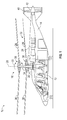
- FIG. 1 Shown in FIG. 1 is schematic view of an embodiment of a rotary wing aircraft, in this embodiment a helicopter 10.
- the helicopter 10 includes an airframe 12 with an extending tail 14.
- a dual, counter rotating coaxial main rotor assembly 18 is located at the airframe 12 and rotates about a main rotor axis 20.
- the main rotor assembly 18 is driven by a power source, for example, an engine 24 via a gearbox 26.
- the main rotor assembly 18 includes an upper rotor assembly 28 driven in a first direction 30 about the main rotor axis 20, and a lower rotor assembly 32 driven in a second direction 34 about the main rotor axis 20, opposite to the first direction 30. While, in FIG.
- the first direction 30 is illustrated as counter-clockwise and the second direction 34 is illustrated as clockwise, it is to be appreciated that in some embodiments the directions of rotation of the upper rotor assembly 28 and lower rotor assembly 32 may be reversed.
- Each of the upper rotor assembly 28 and the lower rotor assembly 32 include a plurality of rotor blades 36 secured to a rotor hub 38.
- the helicopter 10 further includes a translational thrust system 40 located at the extending tail 14 to provide translational thrust for the helicopter 10.
- the translational thrust system 40 includes a propeller rotor 42 connected to and driven by the engine 24 via the gearbox 26. While shown in the context of a pusher-prop configuration, it is understood that the propeller rotor 42 could also be more conventional puller prop or could be variably facing so as to provide yaw control in addition to or instead of translational thrust.
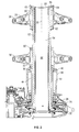
- the lower rotor assembly 32 is driven by a lower rotor quill shaft 44 operably connected to the gearbox 26 at lower rotor bull gear 74 to drive the lower rotor assembly 32 in the second direction 34.
- the lower rotor assembly 32 is connected to the lower rotor quill shaft 44 via, for example, a lower rotor spline connection 46.
- the lower rotor quill shaft 44 carries torque loads of driving the lower rotor assembly 32, while remaining lower rotor loads, such as thrust, shear and head moment, are transferred to a nonrotating static mast 52 through lower rotor bearings 50.
- the static mast 52 is secured to the gearbox 26 and extends along the main rotor axis 20 through the lower rotor quill shaft 44 and through the upper rotor assembly 28.
- An upper rotor quill shaft 54 extends along the main rotor axis 20 through an interior of the static mast 52.
- the upper rotor assembly 28 is operably connected to the gearbox 26 via the upper rotor quill shaft 54 at upper rotor bull gear 76 to drive rotation of the upper rotor assembly 28 in the first direction 30.
- the gearbox 26 in the present embodiment includes bull gears 48 and 56, it is merely exemplary. Other gear types, such as spiral bevel gears, may be utilized.
- the upper rotor quill shaft 54 to connect the upper rotor quill shaft 54 to the upper rotor assembly 28, the upper rotor quill shaft 54 includes an upper shaft flange 56 extending over an upper end 58 of the static mast 52 to the upper rotor assembly 28. At the upper rotor assembly 28, the upper shaft flange 56 is connected to the upper rotor assembly 28 by, for example, an upper rotor spline connection 60. While the upper rotor quill shaft 54 transmits torque loads for driving the upper rotor assembly 28, other upper rotor flight loads such as thrust, shear and head moment, are transferred from the upper rotor assembly 28 into the static mast 52 via upper rotor bearings 62 located between the upper rotor assembly 28 and the static mast 52. The loads are then transferred to the gearbox 26 via the fixed connection of the static mast 52 to the gearbox 26.
- controls for the lower rotor assembly 32 such as control rods, hydraulic lines, electrical leads (not shown in FIG. 2 ) or other controls are conventionally routed outside of the gearbox housing 48 and lower rotor quill shaft 44. In other embodiments such controls could be partially routed through and enclosed in a lower rotor cavity 64 between the gearbox housing 48 and the lower rotor quill shaft 44.
- controls for the upper rotor assembly 28 are routed through an upper rotor quill shaft interior 66 and connected to the upper rotor assembly 28 through an upper shaft opening 68 at an end of the upper rotor quill shaft 54.
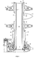
- the static mast 52 provides a nonrotating structure at which to mount an aerodynamic fairing 70 between the upper rotor assembly 28 and the lower rotor assembly 32.
- the static mast 52 may include, for example, an arrangement of studs or bolts 72, which align with openings (not shown) in the fairing 70 and are used to secure the fairing 70 to the static mast 52.
- a fairing 70 is installed on static mast 52, it is to be appreciated that the static mast 52 may be utilized to locate and secure various nonrotating elements, such as radar domes, slip rings, lidar equipment, and the like.
- the fairing 70 may be solid or house components such as electronics of the like.
Landscapes
- Engineering & Computer Science (AREA)
- Mechanical Engineering (AREA)
- Aviation & Aerospace Engineering (AREA)
- Automatic Assembly (AREA)
- Shafts, Cranks, Connecting Bars, And Related Bearings (AREA)
- Turbine Rotor Nozzle Sealing (AREA)
Abstract
Description
- The subject matter disclosed herein relates to the art of rotary wing aircraft and, more specifically, to coaxial multi-rotor systems for rotary wing aircraft.
- In typical rotary winged aircraft, for example, helicopters with dual coaxial rotor systems, rotary power is transmitted from an engine through a gearbox into the rotor system. The gearbox transfers power to a lower rotor shaft to drive a lower rotor assembly and to an upper rotor shaft coaxial with the lower rotor shaft to drive the upper rotor assembly. The systems typically include several sets of bearings between the upper rotor shaft and lower rotor shaft to transfer loads between the shafts. The bearings and controls for the upper rotor assembly drive an increased diameter for the upper rotor shaft, and thus the lower rotor shaft, which increases drag during operation. As such, many coaxial rotor systems include an aerodynamic fairing positioned between the upper rotor assembly and the lower rotor assembly. Typical systems attach to the upper and lower rotor shafts, and include a significant derotation mechanism to prevent the fairing from rotating, and to keep the fairing oriented in a selected direction.
- In one embodiment, a coaxial, dual rotor system includes a first rotor assembly positioned at a rotor axis. A first rotor quill shaft is operably connected to the first rotor assembly at the rotor axis to drive rotation of the first rotor assembly about the rotor axis. A nonrotating static mast extends along the rotor axis inside of the first rotor quill shaft. A second rotor assembly is positioned at the rotor axis. A second rotor quill shaft is operably connected to the second rotor assembly to drive rotation of the second rotor assembly about the rotor axis. The second rotor quill shaft is coaxial with the first rotor quill shaft and disposed inside of the static mast. A second rotor bearing set is positioned between the second rotor assembly and the static mast to transfer loads from the second rotor assembly to the static mast.
- Particular embodiments may include any of the following optional features, alone or in combination:
- The second rotor quill shaft may include a second shaft flange extending from the second rotor quill shaft to connect the second rotor quill shaft to the second rotor assembly.
- The static mast may extend axially through the first rotor assembly and the second rotor assembly.
- The second rotor quill shaft may extend beyond an axial extend of the static mast.
- The rotor system further may comprise an aerodynamic fairing secured to the static mast between the first rotor assembly and the second rotor assembly.
- The aerodynamic fairing may be secured to the static mast via a plurality of fasteners extending from the static mast.
- The static mast may be secured to a gearbox.
- The rotor system further may comprise a first rotor bearing disposed between a first rotor assembly and a gearbox housing to transfer loads from the first rotor assembly to the gearbox housing.
- Controls for the first rotor assembly may be routed between the first rotor quill shaft and a gearbox housing.
- Controls for the second rotor assembly may be routed through an interior of the second rotor quill shaft.
- In another embodiment, a dual coaxial rotor rotorcraft includes an airframe; a drive system positioned at the airframe and a coaxial, dual rotor system operably connected to the drive system. The rotor system includes a first rotor assembly positioned at a rotor axis. A first rotor quill shaft is operably connected to the first rotor assembly at the rotor axis to drive rotation of the first rotor assembly about the rotor axis. A nonrotating static mast extends along the rotor axis inside of the first rotor quill shaft. A second rotor assembly is positioned at the rotor axis. A second rotor quill shaft is operably connected to the second rotor assembly to drive rotation of the second rotor assembly about the rotor axis. The second rotor quill shaft is coaxial with the first rotor quill shaft and disposed inside of the static mast. A second rotor bearing is positioned between the second rotor assembly and the static mast to transfer loads from the second rotor assembly to the static mast.
- Particular embodiments may include any of the following optional features, alone or in combination:
- The second rotor quill shaft may include a second shaft flange extending from the second rotor quill shaft to connect the second rotor quill shaft to the second rotor assembly.
- The static mast may extend axially through the first rotor assembly and the second rotor assembly.
- The second rotor quill shaft may extend beyond an axial extend of the static mast.
- The rotorcraft further may comprise an aerodynamic fairing secured to the static mast between the first rotor assembly and the second rotor assembly.
- The aerodynamic fairing may be secured to the static mast via a plurality of fasteners extending from the static mast.
- The static mast may be secured to a gearbox of the drive system.
- The rotorcraft further may comprise a first rotor bearing disposed between a first rotor assembly and a gearbox housing to transfer loads from the first rotor assembly to the gearbox housing.
- Controls for the first rotor assembly may be routed between the first rotor quill shaft and a gearbox housing.
- Controls for the second rotor assembly may be routed through an interior of the second rotor quill shaft.
- These and other advantages and features will become more apparent from the following description taken in conjunction with the drawings.
- The subject matter, which is regarded as the invention, is particularly pointed out and distinctly claimed in the claims at the conclusion of the specification. The foregoing and other features, and advantages of the invention are apparent from the following detailed description taken in conjunction with the accompanying drawings in which:
-
FIG. 1 is a schematic view of an embodiment of a rotary wing aircraft; -
FIG. 2 is a cross-sectional view of an embodiment of a dual coaxial rotor system; -
FIG. 3 is a cross-sectional view of an embodiment of an upper rotor shaft connection to an upper rotor assembly; and -
FIG. 4 is another embodiment of a dual coaxial rotor system. - The detailed description explains embodiments of the invention, together with advantages and features, by way of example with reference to the drawings.
- Shown in
FIG. 1 is schematic view of an embodiment of a rotary wing aircraft, in this embodiment ahelicopter 10. Thehelicopter 10 includes anairframe 12 with an extendingtail 14. A dual, counter rotating coaxialmain rotor assembly 18 is located at theairframe 12 and rotates about amain rotor axis 20. Themain rotor assembly 18 is driven by a power source, for example, anengine 24 via agearbox 26. Themain rotor assembly 18 includes anupper rotor assembly 28 driven in afirst direction 30 about themain rotor axis 20, and alower rotor assembly 32 driven in asecond direction 34 about themain rotor axis 20, opposite to thefirst direction 30. While, inFIG. 1 , thefirst direction 30 is illustrated as counter-clockwise and thesecond direction 34 is illustrated as clockwise, it is to be appreciated that in some embodiments the directions of rotation of theupper rotor assembly 28 andlower rotor assembly 32 may be reversed. Each of theupper rotor assembly 28 and thelower rotor assembly 32 include a plurality ofrotor blades 36 secured to arotor hub 38. In some embodiments, thehelicopter 10 further includes atranslational thrust system 40 located at the extendingtail 14 to provide translational thrust for thehelicopter 10. Thetranslational thrust system 40 includes apropeller rotor 42 connected to and driven by theengine 24 via thegearbox 26. While shown in the context of a pusher-prop configuration, it is understood that thepropeller rotor 42 could also be more conventional puller prop or could be variably facing so as to provide yaw control in addition to or instead of translational thrust. - Referring to
FIG. 2 , thelower rotor assembly 32 is driven by a lowerrotor quill shaft 44 operably connected to thegearbox 26 at lowerrotor bull gear 74 to drive thelower rotor assembly 32 in thesecond direction 34. Thelower rotor assembly 32 is connected to the lowerrotor quill shaft 44 via, for example, a lowerrotor spline connection 46. The lowerrotor quill shaft 44 carries torque loads of driving thelower rotor assembly 32, while remaining lower rotor loads, such as thrust, shear and head moment, are transferred to a nonrotatingstatic mast 52 throughlower rotor bearings 50. Thestatic mast 52 is secured to thegearbox 26 and extends along themain rotor axis 20 through the lowerrotor quill shaft 44 and through theupper rotor assembly 28. An upperrotor quill shaft 54 extends along themain rotor axis 20 through an interior of thestatic mast 52. Theupper rotor assembly 28 is operably connected to thegearbox 26 via the upperrotor quill shaft 54 at upperrotor bull gear 76 to drive rotation of theupper rotor assembly 28 in thefirst direction 30. While thegearbox 26 in the present embodiment includes bull gears 48 and 56, it is merely exemplary. Other gear types, such as spiral bevel gears, may be utilized. - Referring to
FIG. 3 , to connect the upperrotor quill shaft 54 to theupper rotor assembly 28, the upperrotor quill shaft 54 includes anupper shaft flange 56 extending over anupper end 58 of thestatic mast 52 to theupper rotor assembly 28. At theupper rotor assembly 28, theupper shaft flange 56 is connected to theupper rotor assembly 28 by, for example, an upperrotor spline connection 60. While the upperrotor quill shaft 54 transmits torque loads for driving theupper rotor assembly 28, other upper rotor flight loads such as thrust, shear and head moment, are transferred from theupper rotor assembly 28 into thestatic mast 52 viaupper rotor bearings 62 located between theupper rotor assembly 28 and thestatic mast 52. The loads are then transferred to thegearbox 26 via the fixed connection of thestatic mast 52 to thegearbox 26. - Referring again to
FIG. 2 , in some embodiments, controls for thelower rotor assembly 32, such as control rods, hydraulic lines, electrical leads (not shown inFIG. 2 ) or other controls are conventionally routed outside of thegearbox housing 48 and lowerrotor quill shaft 44. In other embodiments such controls could be partially routed through and enclosed in alower rotor cavity 64 between thegearbox housing 48 and the lowerrotor quill shaft 44. Similarly, in some embodiments, controls for theupper rotor assembly 28 are routed through an upper rotorquill shaft interior 66 and connected to theupper rotor assembly 28 through an upper shaft opening 68 at an end of the upperrotor quill shaft 54. - Referring now to
FIG. 4 , thestatic mast 52 provides a nonrotating structure at which to mount anaerodynamic fairing 70 between theupper rotor assembly 28 and thelower rotor assembly 32. To facilitate installation of the fairing 70, thestatic mast 52 may include, for example, an arrangement of studs orbolts 72, which align with openings (not shown) in thefairing 70 and are used to secure the fairing 70 to thestatic mast 52. While in the embodiment shown, a fairing 70 is installed onstatic mast 52, it is to be appreciated that thestatic mast 52 may be utilized to locate and secure various nonrotating elements, such as radar domes, slip rings, lidar equipment, and the like. Further, while illustrated as empty, is to be appreciated that the fairing 70 may be solid or house components such as electronics of the like. - While the invention has been described in detail in connection with only a limited number of embodiments, it should be readily understood that the invention is not limited to such disclosed embodiments. Rather, the invention can be modified to incorporate any number of variations, alterations, substitutions or equivalent arrangements not heretofore described, but which are commensurate with the spirit and scope of the invention. For instance, aspects can be used with propeller assemblies, turbines, and/or fans. Additionally, while various embodiments of the invention have been described, it is to be understood that aspects of the invention may include only some of the described embodiments. Accordingly, the invention is not to be seen as limited by the foregoing description, but is only limited by the scope of the appended claims.
Claims (11)
- A coaxial, dual rotor system (18) comprising:a first rotor assembly (32) disposed at a rotor axis (20);a first rotor quill shaft (44) operably connected to the first rotor assembly (32) at the rotor axis (20) to drive rotation of the first rotor assembly (32) about the rotor axis (20);a nonrotating static mast (52) extending along the rotor axis (20) inside of the first rotor quill shaft (44);a second rotor assembly (28) disposed at the rotor axis (20);a second rotor quill shaft (54) operably connected to the second rotor assembly (28) to drive rotation of the second rotor assembly (28) about the rotor axis (20), the second rotor quill shaft (54) coaxial with the first rotor quill shaft (44) and disposed inside of the static mast (52); anda second rotor bearing (62) disposed between the second rotor assembly (28) and the static mast (52) to transfer loads from the second rotor assembly (28) to the static mast (52).
- The rotor system (18) of Claim 1, wherein the second rotor quill shaft (54) includes a second shaft flange (56) extending from the second rotor quill shaft (54) to connect the second rotor quill shaft (54) to the second rotor assembly (28).
- The rotor system (18) of Claim 1 or 2, wherein the static mast (52) extends axially through the first rotor assembly (32) and the second rotor assembly (28).
- The rotor system (18) of any of Claims 1 to 3, wherein the second rotor quill shaft (54) extends beyond an axial extend of the static mast (52).
- The rotor system (18) of any of Claims 1 to 4, further comprising an aerodynamic fairing (70) secured to the static mast (52) between the first rotor assembly (32) and the second rotor assembly (28).
- The rotor system (18) of Claim 5, wherein the aerodynamic fairing (70) is secured to the static mast (52) via a plurality of fasteners (72) extending from the static mast (52).
- The rotor system (18) of any of Claims 1 to 6, wherein the static mast (52) is secured to a gearbox (26).
- The rotor system (18) of any of Claims 1 to 7, further comprising a first rotor bearing (50) disposed between a first rotor assembly (32) and a gearbox housing (26) to transfer loads from the first rotor assembly (32) to the gearbox housing (26).
- The rotor system (18) of any of Claims 1 to 8, wherein controls for the first rotor assembly (32) are routed between the first rotor quill shaft (44) and a gearbox housing (26).
- The rotor system (18) of any of Claims 1 to 9, wherein controls for the second rotor assembly (28) are routed through an interior (66) of the second rotor quill shaft (54).
- A dual coaxial rotor rotorcraft (10) comprising:an airframe (12);a drive system (24, 26) disposed at the airframe (12); anda coaxial, dual rotor system (18) according to any of the previous claims, said coaxial, dual rotor system (18) operably connected to the drive system (24, 26).
Applications Claiming Priority (1)
| Application Number | Priority Date | Filing Date | Title |
|---|---|---|---|
| US14/081,300 US9725166B2 (en) | 2013-11-15 | 2013-11-15 | Counter-rotating rotor system with static mast |
Publications (2)
| Publication Number | Publication Date |
|---|---|
| EP2873613A1 true EP2873613A1 (en) | 2015-05-20 |
| EP2873613B1 EP2873613B1 (en) | 2018-05-02 |
Family
ID=51866033
Family Applications (1)
| Application Number | Title | Priority Date | Filing Date |
|---|---|---|---|
| EP14191856.5A Not-in-force EP2873613B1 (en) | 2013-11-15 | 2014-11-05 | Counter-rotating rotor system with static mast |
Country Status (2)
| Country | Link |
|---|---|
| US (1) | US9725166B2 (en) |
| EP (1) | EP2873613B1 (en) |
Families Citing this family (5)
| Publication number | Priority date | Publication date | Assignee | Title |
|---|---|---|---|---|
| US20170267338A1 (en) | 2014-10-01 | 2017-09-21 | Sikorsky Aircraft Corporation | Acoustic signature variation of aircraft utilizing a clutch |
| US20170113790A1 (en) * | 2015-10-21 | 2017-04-27 | Sikorsky Aircraft Corporation | Fairing with integrated sensory system of a rotary-wing aircraft |
| US10017247B1 (en) * | 2017-06-02 | 2018-07-10 | Bell Helicopter Textron Inc. | Rotor mast assembly |
| RU2729900C9 (en) * | 2019-12-30 | 2020-11-26 | Акционерное общество "Национальный центр вертолетостроения им. М.Л. Миля и Н.И. Камова" (АО "НЦВ Миль и Камов") | Drive system of coaxial rotors of helicopter with support mast |
| CN116142475A (en) * | 2023-04-06 | 2023-05-23 | 南方海洋科学与工程广东省实验室(珠海) | A Meteorological Detection UAV Suitable for Multi-task Switching |
Citations (3)
| Publication number | Priority date | Publication date | Assignee | Title |
|---|---|---|---|---|
| FR2406565A1 (en) * | 1977-10-18 | 1979-05-18 | Mendiberri Vicente | HELICOPTER WITH TWO CONTRAROTATING COAXIAL ROTORS |
| US6293492B1 (en) * | 1998-09-02 | 2001-09-25 | Engineering System Co., Ltd. | Coaxial twin-rotor type helicopter |
| US20060269411A1 (en) * | 2005-05-31 | 2006-11-30 | Bertolotti Fabio P | Rotor hub fairing system for a counter-rotating, coaxial rotor system |
Family Cites Families (11)
| Publication number | Priority date | Publication date | Assignee | Title |
|---|---|---|---|---|
| US3409249A (en) * | 1966-06-29 | 1968-11-05 | United Aircraft Corp | Coaxial rigid rotor helicopter and method of flying same |
| US4531692A (en) * | 1982-03-15 | 1985-07-30 | Ernesto Mateus | Helicopter flight control and transmission system |
| US4573873A (en) | 1983-01-13 | 1986-03-04 | Hughes Helicopters, Inc. | Collective and cyclic in-mast pitch control system for a helicopter |
| US4730795A (en) * | 1984-03-26 | 1988-03-15 | David Constant V | Heliplane |
| US5154371A (en) | 1991-04-10 | 1992-10-13 | United Technologies Corporation | Main rotor assembly support truss |
| US5351913A (en) | 1992-06-22 | 1994-10-04 | United Technologies Corporation | Coaxial transmission/center hub subassembly for a rotor assembly having ducted, coaxial counter-rotating rotors |
| US5791592A (en) * | 1995-01-18 | 1998-08-11 | Nolan; Herbert M. | Helicopter with coaxial counter-rotating dual rotors and no tail rotor |
| FR2771707B1 (en) | 1997-11-28 | 2000-02-04 | Eurocopter France | SWIM PLATE CONTROL DEVICE FOR THE PITCH OF THE BLADES OF A ROTOR WITH CYLINDRICAL SKATES SLIDING ON NON-ROTATING COLUMNS |
| US7118340B2 (en) | 2004-09-10 | 2006-10-10 | Sikorsky Aircraft Corporation | Swashplate and pitch link arrangement for a coaxial counter rotating rotor system |
| US7621480B2 (en) * | 2005-05-26 | 2009-11-24 | Sikorsky Aircraft Corporation | De-rotation system for a counter-rotating, coaxial rotor hub shaft fairing |
| DE602007014016D1 (en) | 2007-05-11 | 2011-06-01 | Hubert Antoine | Opposing coaxial helicopter rotor |
-
2013
- 2013-11-15 US US14/081,300 patent/US9725166B2/en not_active Expired - Fee Related
-
2014
- 2014-11-05 EP EP14191856.5A patent/EP2873613B1/en not_active Not-in-force
Patent Citations (3)
| Publication number | Priority date | Publication date | Assignee | Title |
|---|---|---|---|---|
| FR2406565A1 (en) * | 1977-10-18 | 1979-05-18 | Mendiberri Vicente | HELICOPTER WITH TWO CONTRAROTATING COAXIAL ROTORS |
| US6293492B1 (en) * | 1998-09-02 | 2001-09-25 | Engineering System Co., Ltd. | Coaxial twin-rotor type helicopter |
| US20060269411A1 (en) * | 2005-05-31 | 2006-11-30 | Bertolotti Fabio P | Rotor hub fairing system for a counter-rotating, coaxial rotor system |
Also Published As
| Publication number | Publication date |
|---|---|
| US9725166B2 (en) | 2017-08-08 |
| US20150139799A1 (en) | 2015-05-21 |
| EP2873613B1 (en) | 2018-05-02 |
Similar Documents
| Publication | Publication Date | Title |
|---|---|---|
| US9623964B2 (en) | Counter-rotating rotor system with stationary standpipe | |
| US10053212B2 (en) | Transmission for coaxial multi-rotor system | |
| EP3038906B1 (en) | Light weight propulsor gearbox | |
| US20090140095A1 (en) | Electric powered rotary-wing aircraft | |
| US20170158323A1 (en) | Tiltrotor with Inboard Engines | |
| EP2873613B1 (en) | Counter-rotating rotor system with static mast | |
| US20180105263A1 (en) | Electric propulsion system for a rotary wing aircraft | |
| US11338915B2 (en) | Rotor systems and methods | |
| EP3760536B1 (en) | Aeronautical propelling device | |
| US11161606B2 (en) | Flexured standpipes for aircraft propulsion assemblies | |
| US10724625B2 (en) | Torsionally compliant geartrain carrier assembly | |
| KR102251286B1 (en) | Aircraft rotors capable of hovering | |
| US11498670B2 (en) | Coaxial split torque gear box | |
| EP4328133B1 (en) | Rotary shaft for an aircraft | |
| US20170050727A1 (en) | Radially compliant quill shaft | |
| US20170137121A1 (en) | Flex beam clamp for rotor assembly | |
| EP3842342A1 (en) | Fail-safe tail rotor system | |
| US10941836B2 (en) | Rotorcraft internal transfer member transmission | |
| EP2873612A1 (en) | Counter-rotating rotor system with fairing | |
| US10703472B2 (en) | Directional control for coaxial rotary wing craft | |
| US11066158B2 (en) | Low drag high capacity pitch bearing for rigid rotor aircraft | |
| US20170297688A1 (en) | Integrated main rotor hub and shaft | |
| NO344389B1 (en) | A system for variable blade pitch control and autorotation for electrically powered rotorcraft |
Legal Events
| Date | Code | Title | Description |
|---|---|---|---|
| PUAI | Public reference made under article 153(3) epc to a published international application that has entered the european phase |
Free format text: ORIGINAL CODE: 0009012 |
|
| 17P | Request for examination filed |
Effective date: 20141105 |
|
| AK | Designated contracting states |
Kind code of ref document: A1 Designated state(s): AL AT BE BG CH CY CZ DE DK EE ES FI FR GB GR HR HU IE IS IT LI LT LU LV MC MK MT NL NO PL PT RO RS SE SI SK SM TR |
|
| AX | Request for extension of the european patent |
Extension state: BA ME |
|
| R17P | Request for examination filed (corrected) |
Effective date: 20151120 |
|
| RBV | Designated contracting states (corrected) |
Designated state(s): AL AT BE BG CH CY CZ DE DK EE ES FI FR GB GR HR HU IE IS IT LI LT LU LV MC MK MT NL NO PL PT RO RS SE SI SK SM TR |
|
| GRAP | Despatch of communication of intention to grant a patent |
Free format text: ORIGINAL CODE: EPIDOSNIGR1 |
|
| INTG | Intention to grant announced |
Effective date: 20171122 |
|
| GRAS | Grant fee paid |
Free format text: ORIGINAL CODE: EPIDOSNIGR3 |
|
| GRAA | (expected) grant |
Free format text: ORIGINAL CODE: 0009210 |
|
| AK | Designated contracting states |
Kind code of ref document: B1 Designated state(s): AL AT BE BG CH CY CZ DE DK EE ES FI FR GB GR HR HU IE IS IT LI LT LU LV MC MK MT NL NO PL PT RO RS SE SI SK SM TR |
|
| REG | Reference to a national code |
Ref country code: GB Ref legal event code: FG4D |
|
| REG | Reference to a national code |
Ref country code: CH Ref legal event code: EP Ref country code: AT Ref legal event code: REF Ref document number: 994947 Country of ref document: AT Kind code of ref document: T Effective date: 20180515 |
|
| REG | Reference to a national code |
Ref country code: DE Ref legal event code: R096 Ref document number: 602014024780 Country of ref document: DE Ref country code: IE Ref legal event code: FG4D |
|
| REG | Reference to a national code |
Ref country code: NL Ref legal event code: MP Effective date: 20180502 |
|
| REG | Reference to a national code |
Ref country code: LT Ref legal event code: MG4D |
|
| PG25 | Lapsed in a contracting state [announced via postgrant information from national office to epo] |
Ref country code: ES Free format text: LAPSE BECAUSE OF FAILURE TO SUBMIT A TRANSLATION OF THE DESCRIPTION OR TO PAY THE FEE WITHIN THE PRESCRIBED TIME-LIMIT Effective date: 20180502 Ref country code: BG Free format text: LAPSE BECAUSE OF FAILURE TO SUBMIT A TRANSLATION OF THE DESCRIPTION OR TO PAY THE FEE WITHIN THE PRESCRIBED TIME-LIMIT Effective date: 20180802 Ref country code: NO Free format text: LAPSE BECAUSE OF FAILURE TO SUBMIT A TRANSLATION OF THE DESCRIPTION OR TO PAY THE FEE WITHIN THE PRESCRIBED TIME-LIMIT Effective date: 20180802 Ref country code: LT Free format text: LAPSE BECAUSE OF FAILURE TO SUBMIT A TRANSLATION OF THE DESCRIPTION OR TO PAY THE FEE WITHIN THE PRESCRIBED TIME-LIMIT Effective date: 20180502 Ref country code: FI Free format text: LAPSE BECAUSE OF FAILURE TO SUBMIT A TRANSLATION OF THE DESCRIPTION OR TO PAY THE FEE WITHIN THE PRESCRIBED TIME-LIMIT Effective date: 20180502 Ref country code: SE Free format text: LAPSE BECAUSE OF FAILURE TO SUBMIT A TRANSLATION OF THE DESCRIPTION OR TO PAY THE FEE WITHIN THE PRESCRIBED TIME-LIMIT Effective date: 20180502 |
|
| PG25 | Lapsed in a contracting state [announced via postgrant information from national office to epo] |
Ref country code: HR Free format text: LAPSE BECAUSE OF FAILURE TO SUBMIT A TRANSLATION OF THE DESCRIPTION OR TO PAY THE FEE WITHIN THE PRESCRIBED TIME-LIMIT Effective date: 20180502 Ref country code: GR Free format text: LAPSE BECAUSE OF FAILURE TO SUBMIT A TRANSLATION OF THE DESCRIPTION OR TO PAY THE FEE WITHIN THE PRESCRIBED TIME-LIMIT Effective date: 20180803 Ref country code: LV Free format text: LAPSE BECAUSE OF FAILURE TO SUBMIT A TRANSLATION OF THE DESCRIPTION OR TO PAY THE FEE WITHIN THE PRESCRIBED TIME-LIMIT Effective date: 20180502 Ref country code: NL Free format text: LAPSE BECAUSE OF FAILURE TO SUBMIT A TRANSLATION OF THE DESCRIPTION OR TO PAY THE FEE WITHIN THE PRESCRIBED TIME-LIMIT Effective date: 20180502 Ref country code: RS Free format text: LAPSE BECAUSE OF FAILURE TO SUBMIT A TRANSLATION OF THE DESCRIPTION OR TO PAY THE FEE WITHIN THE PRESCRIBED TIME-LIMIT Effective date: 20180502 |
|
| REG | Reference to a national code |
Ref country code: AT Ref legal event code: MK05 Ref document number: 994947 Country of ref document: AT Kind code of ref document: T Effective date: 20180502 |
|
| PG25 | Lapsed in a contracting state [announced via postgrant information from national office to epo] |
Ref country code: CZ Free format text: LAPSE BECAUSE OF FAILURE TO SUBMIT A TRANSLATION OF THE DESCRIPTION OR TO PAY THE FEE WITHIN THE PRESCRIBED TIME-LIMIT Effective date: 20180502 Ref country code: RO Free format text: LAPSE BECAUSE OF FAILURE TO SUBMIT A TRANSLATION OF THE DESCRIPTION OR TO PAY THE FEE WITHIN THE PRESCRIBED TIME-LIMIT Effective date: 20180502 Ref country code: SK Free format text: LAPSE BECAUSE OF FAILURE TO SUBMIT A TRANSLATION OF THE DESCRIPTION OR TO PAY THE FEE WITHIN THE PRESCRIBED TIME-LIMIT Effective date: 20180502 Ref country code: AT Free format text: LAPSE BECAUSE OF FAILURE TO SUBMIT A TRANSLATION OF THE DESCRIPTION OR TO PAY THE FEE WITHIN THE PRESCRIBED TIME-LIMIT Effective date: 20180502 Ref country code: DK Free format text: LAPSE BECAUSE OF FAILURE TO SUBMIT A TRANSLATION OF THE DESCRIPTION OR TO PAY THE FEE WITHIN THE PRESCRIBED TIME-LIMIT Effective date: 20180502 Ref country code: PL Free format text: LAPSE BECAUSE OF FAILURE TO SUBMIT A TRANSLATION OF THE DESCRIPTION OR TO PAY THE FEE WITHIN THE PRESCRIBED TIME-LIMIT Effective date: 20180502 Ref country code: EE Free format text: LAPSE BECAUSE OF FAILURE TO SUBMIT A TRANSLATION OF THE DESCRIPTION OR TO PAY THE FEE WITHIN THE PRESCRIBED TIME-LIMIT Effective date: 20180502 |
|
| REG | Reference to a national code |
Ref country code: DE Ref legal event code: R097 Ref document number: 602014024780 Country of ref document: DE |
|
| PG25 | Lapsed in a contracting state [announced via postgrant information from national office to epo] |
Ref country code: SM Free format text: LAPSE BECAUSE OF FAILURE TO SUBMIT A TRANSLATION OF THE DESCRIPTION OR TO PAY THE FEE WITHIN THE PRESCRIBED TIME-LIMIT Effective date: 20180502 |
|
| PLBE | No opposition filed within time limit |
Free format text: ORIGINAL CODE: 0009261 |
|
| STAA | Information on the status of an ep patent application or granted ep patent |
Free format text: STATUS: NO OPPOSITION FILED WITHIN TIME LIMIT |
|
| 26N | No opposition filed |
Effective date: 20190205 |
|
| PG25 | Lapsed in a contracting state [announced via postgrant information from national office to epo] |
Ref country code: SI Free format text: LAPSE BECAUSE OF FAILURE TO SUBMIT A TRANSLATION OF THE DESCRIPTION OR TO PAY THE FEE WITHIN THE PRESCRIBED TIME-LIMIT Effective date: 20180502 |
|
| REG | Reference to a national code |
Ref country code: CH Ref legal event code: PL |
|
| PG25 | Lapsed in a contracting state [announced via postgrant information from national office to epo] |
Ref country code: MC Free format text: LAPSE BECAUSE OF FAILURE TO SUBMIT A TRANSLATION OF THE DESCRIPTION OR TO PAY THE FEE WITHIN THE PRESCRIBED TIME-LIMIT Effective date: 20180502 Ref country code: LU Free format text: LAPSE BECAUSE OF NON-PAYMENT OF DUE FEES Effective date: 20181105 |
|
| REG | Reference to a national code |
Ref country code: BE Ref legal event code: MM Effective date: 20181130 |
|
| REG | Reference to a national code |
Ref country code: IE Ref legal event code: MM4A |
|
| PG25 | Lapsed in a contracting state [announced via postgrant information from national office to epo] |
Ref country code: LI Free format text: LAPSE BECAUSE OF NON-PAYMENT OF DUE FEES Effective date: 20181130 Ref country code: CH Free format text: LAPSE BECAUSE OF NON-PAYMENT OF DUE FEES Effective date: 20181130 |
|
| PG25 | Lapsed in a contracting state [announced via postgrant information from national office to epo] |
Ref country code: IE Free format text: LAPSE BECAUSE OF NON-PAYMENT OF DUE FEES Effective date: 20181105 |
|
| PG25 | Lapsed in a contracting state [announced via postgrant information from national office to epo] |
Ref country code: AL Free format text: LAPSE BECAUSE OF FAILURE TO SUBMIT A TRANSLATION OF THE DESCRIPTION OR TO PAY THE FEE WITHIN THE PRESCRIBED TIME-LIMIT Effective date: 20180502 Ref country code: BE Free format text: LAPSE BECAUSE OF NON-PAYMENT OF DUE FEES Effective date: 20181130 |
|
| PG25 | Lapsed in a contracting state [announced via postgrant information from national office to epo] |
Ref country code: MT Free format text: LAPSE BECAUSE OF NON-PAYMENT OF DUE FEES Effective date: 20181105 |
|
| PG25 | Lapsed in a contracting state [announced via postgrant information from national office to epo] |
Ref country code: TR Free format text: LAPSE BECAUSE OF FAILURE TO SUBMIT A TRANSLATION OF THE DESCRIPTION OR TO PAY THE FEE WITHIN THE PRESCRIBED TIME-LIMIT Effective date: 20180502 |
|
| PG25 | Lapsed in a contracting state [announced via postgrant information from national office to epo] |
Ref country code: PT Free format text: LAPSE BECAUSE OF FAILURE TO SUBMIT A TRANSLATION OF THE DESCRIPTION OR TO PAY THE FEE WITHIN THE PRESCRIBED TIME-LIMIT Effective date: 20180502 |
|
| PG25 | Lapsed in a contracting state [announced via postgrant information from national office to epo] |
Ref country code: MK Free format text: LAPSE BECAUSE OF NON-PAYMENT OF DUE FEES Effective date: 20180502 Ref country code: HU Free format text: LAPSE BECAUSE OF FAILURE TO SUBMIT A TRANSLATION OF THE DESCRIPTION OR TO PAY THE FEE WITHIN THE PRESCRIBED TIME-LIMIT; INVALID AB INITIO Effective date: 20141105 Ref country code: CY Free format text: LAPSE BECAUSE OF FAILURE TO SUBMIT A TRANSLATION OF THE DESCRIPTION OR TO PAY THE FEE WITHIN THE PRESCRIBED TIME-LIMIT Effective date: 20180502 |
|
| PG25 | Lapsed in a contracting state [announced via postgrant information from national office to epo] |
Ref country code: IS Free format text: LAPSE BECAUSE OF FAILURE TO SUBMIT A TRANSLATION OF THE DESCRIPTION OR TO PAY THE FEE WITHIN THE PRESCRIBED TIME-LIMIT Effective date: 20180902 |
|
| PGFP | Annual fee paid to national office [announced via postgrant information from national office to epo] |
Ref country code: GB Payment date: 20201127 Year of fee payment: 7 Ref country code: FR Payment date: 20201125 Year of fee payment: 7 Ref country code: IT Payment date: 20201123 Year of fee payment: 7 Ref country code: DE Payment date: 20201127 Year of fee payment: 7 |
|
| REG | Reference to a national code |
Ref country code: DE Ref legal event code: R119 Ref document number: 602014024780 Country of ref document: DE |
|
| GBPC | Gb: european patent ceased through non-payment of renewal fee |
Effective date: 20211105 |
|
| PG25 | Lapsed in a contracting state [announced via postgrant information from national office to epo] |
Ref country code: GB Free format text: LAPSE BECAUSE OF NON-PAYMENT OF DUE FEES Effective date: 20211105 Ref country code: DE Free format text: LAPSE BECAUSE OF NON-PAYMENT OF DUE FEES Effective date: 20220601 |
|
| PG25 | Lapsed in a contracting state [announced via postgrant information from national office to epo] |
Ref country code: FR Free format text: LAPSE BECAUSE OF NON-PAYMENT OF DUE FEES Effective date: 20211130 |
|
| PG25 | Lapsed in a contracting state [announced via postgrant information from national office to epo] |
Ref country code: IT Free format text: LAPSE BECAUSE OF NON-PAYMENT OF DUE FEES Effective date: 20211105 |
|
| P01 | Opt-out of the competence of the unified patent court (upc) registered |
Effective date: 20230520 |