EP2873549A1 - Connecting structure of main transformer and high-voltage device box, and railroad vehicle comprising said structure - Google Patents
Connecting structure of main transformer and high-voltage device box, and railroad vehicle comprising said structure Download PDFInfo
- Publication number
- EP2873549A1 EP2873549A1 EP20130816265 EP13816265A EP2873549A1 EP 2873549 A1 EP2873549 A1 EP 2873549A1 EP 20130816265 EP20130816265 EP 20130816265 EP 13816265 A EP13816265 A EP 13816265A EP 2873549 A1 EP2873549 A1 EP 2873549A1
- Authority
- EP
- European Patent Office
- Prior art keywords
- voltage
- cable
- main transformer
- connector
- device box
- Prior art date
- Legal status (The legal status is an assumption and is not a legal conclusion. Google has not performed a legal analysis and makes no representation as to the accuracy of the status listed.)
- Withdrawn
Links
Images


Classifications
-
- H—ELECTRICITY
- H02—GENERATION; CONVERSION OR DISTRIBUTION OF ELECTRIC POWER
- H02B—BOARDS, SUBSTATIONS OR SWITCHING ARRANGEMENTS FOR THE SUPPLY OR DISTRIBUTION OF ELECTRIC POWER
- H02B1/00—Frameworks, boards, panels, desks, casings; Details of substations or switching arrangements
- H02B1/26—Casings; Parts thereof or accessories therefor
- H02B1/46—Boxes; Parts thereof or accessories therefor
-
- B—PERFORMING OPERATIONS; TRANSPORTING
- B60—VEHICLES IN GENERAL
- B60L—PROPULSION OF ELECTRICALLY-PROPELLED VEHICLES; SUPPLYING ELECTRIC POWER FOR AUXILIARY EQUIPMENT OF ELECTRICALLY-PROPELLED VEHICLES; ELECTRODYNAMIC BRAKE SYSTEMS FOR VEHICLES IN GENERAL; MAGNETIC SUSPENSION OR LEVITATION FOR VEHICLES; MONITORING OPERATING VARIABLES OF ELECTRICALLY-PROPELLED VEHICLES; ELECTRIC SAFETY DEVICES FOR ELECTRICALLY-PROPELLED VEHICLES
- B60L3/00—Electric devices on electrically-propelled vehicles for safety purposes; Monitoring operating variables, e.g. speed, deceleration or energy consumption
- B60L3/0023—Detecting, eliminating, remedying or compensating for drive train abnormalities, e.g. failures within the drive train
- B60L3/0069—Detecting, eliminating, remedying or compensating for drive train abnormalities, e.g. failures within the drive train relating to the isolation, e.g. ground fault or leak current
-
- B—PERFORMING OPERATIONS; TRANSPORTING
- B60—VEHICLES IN GENERAL
- B60L—PROPULSION OF ELECTRICALLY-PROPELLED VEHICLES; SUPPLYING ELECTRIC POWER FOR AUXILIARY EQUIPMENT OF ELECTRICALLY-PROPELLED VEHICLES; ELECTRODYNAMIC BRAKE SYSTEMS FOR VEHICLES IN GENERAL; MAGNETIC SUSPENSION OR LEVITATION FOR VEHICLES; MONITORING OPERATING VARIABLES OF ELECTRICALLY-PROPELLED VEHICLES; ELECTRIC SAFETY DEVICES FOR ELECTRICALLY-PROPELLED VEHICLES
- B60L3/00—Electric devices on electrically-propelled vehicles for safety purposes; Monitoring operating variables, e.g. speed, deceleration or energy consumption
- B60L3/04—Cutting off the power supply under fault conditions
-
- B—PERFORMING OPERATIONS; TRANSPORTING
- B60—VEHICLES IN GENERAL
- B60L—PROPULSION OF ELECTRICALLY-PROPELLED VEHICLES; SUPPLYING ELECTRIC POWER FOR AUXILIARY EQUIPMENT OF ELECTRICALLY-PROPELLED VEHICLES; ELECTRODYNAMIC BRAKE SYSTEMS FOR VEHICLES IN GENERAL; MAGNETIC SUSPENSION OR LEVITATION FOR VEHICLES; MONITORING OPERATING VARIABLES OF ELECTRICALLY-PROPELLED VEHICLES; ELECTRIC SAFETY DEVICES FOR ELECTRICALLY-PROPELLED VEHICLES
- B60L9/00—Electric propulsion with power supply external to the vehicle
- B60L9/16—Electric propulsion with power supply external to the vehicle using AC induction motors
- B60L9/24—Electric propulsion with power supply external to the vehicle using AC induction motors fed from AC supply lines
-
- B—PERFORMING OPERATIONS; TRANSPORTING
- B61—RAILWAYS
- B61C—LOCOMOTIVES; MOTOR RAILCARS
- B61C17/00—Arrangement or disposition of parts; Details or accessories not otherwise provided for; Use of control gear and control systems
- B61C17/12—Control gear; Arrangements for controlling locomotives from remote points in the train or when operating in multiple units
-
- B—PERFORMING OPERATIONS; TRANSPORTING
- B61—RAILWAYS
- B61C—LOCOMOTIVES; MOTOR RAILCARS
- B61C3/00—Electric locomotives or railcars
-
- B—PERFORMING OPERATIONS; TRANSPORTING
- B61—RAILWAYS
- B61G—COUPLINGS; DRAUGHT AND BUFFING APPLIANCES
- B61G5/00—Couplings for special purposes not otherwise provided for
- B61G5/06—Couplings for special purposes not otherwise provided for for, or combined with, couplings or connectors for fluid conduits or electric cables
- B61G5/10—Couplings for special purposes not otherwise provided for for, or combined with, couplings or connectors for fluid conduits or electric cables for electric cables
-
- H—ELECTRICITY
- H02—GENERATION; CONVERSION OR DISTRIBUTION OF ELECTRIC POWER
- H02B—BOARDS, SUBSTATIONS OR SWITCHING ARRANGEMENTS FOR THE SUPPLY OR DISTRIBUTION OF ELECTRIC POWER
- H02B13/00—Arrangement of switchgear in which switches are enclosed in, or structurally associated with, a casing, e.g. cubicle
- H02B13/005—Electrical connection between switchgear cells
-
- H—ELECTRICITY
- H02—GENERATION; CONVERSION OR DISTRIBUTION OF ELECTRIC POWER
- H02G—INSTALLATION OF ELECTRIC CABLES OR LINES, OR OF COMBINED OPTICAL AND ELECTRIC CABLES OR LINES
- H02G15/00—Cable fittings
- H02G15/02—Cable terminations
-
- H—ELECTRICITY
- H02—GENERATION; CONVERSION OR DISTRIBUTION OF ELECTRIC POWER
- H02G—INSTALLATION OF ELECTRIC CABLES OR LINES, OR OF COMBINED OPTICAL AND ELECTRIC CABLES OR LINES
- H02G15/00—Cable fittings
- H02G15/02—Cable terminations
- H02G15/04—Cable-end sealings
- H02G15/043—Cable-end sealings with end caps, e.g. sleeve closed at one end
- H02G15/046—Cable-end sealings with end caps, e.g. sleeve closed at one end with bores or protruding portions allowing passage of cable conductors
-
- B—PERFORMING OPERATIONS; TRANSPORTING
- B60—VEHICLES IN GENERAL
- B60L—PROPULSION OF ELECTRICALLY-PROPELLED VEHICLES; SUPPLYING ELECTRIC POWER FOR AUXILIARY EQUIPMENT OF ELECTRICALLY-PROPELLED VEHICLES; ELECTRODYNAMIC BRAKE SYSTEMS FOR VEHICLES IN GENERAL; MAGNETIC SUSPENSION OR LEVITATION FOR VEHICLES; MONITORING OPERATING VARIABLES OF ELECTRICALLY-PROPELLED VEHICLES; ELECTRIC SAFETY DEVICES FOR ELECTRICALLY-PROPELLED VEHICLES
- B60L2200/00—Type of vehicles
- B60L2200/26—Rail vehicles
-
- B—PERFORMING OPERATIONS; TRANSPORTING
- B60—VEHICLES IN GENERAL
- B60L—PROPULSION OF ELECTRICALLY-PROPELLED VEHICLES; SUPPLYING ELECTRIC POWER FOR AUXILIARY EQUIPMENT OF ELECTRICALLY-PROPELLED VEHICLES; ELECTRODYNAMIC BRAKE SYSTEMS FOR VEHICLES IN GENERAL; MAGNETIC SUSPENSION OR LEVITATION FOR VEHICLES; MONITORING OPERATING VARIABLES OF ELECTRICALLY-PROPELLED VEHICLES; ELECTRIC SAFETY DEVICES FOR ELECTRICALLY-PROPELLED VEHICLES
- B60L2250/00—Driver interactions
- B60L2250/16—Driver interactions by display
-
- B—PERFORMING OPERATIONS; TRANSPORTING
- B60—VEHICLES IN GENERAL
- B60L—PROPULSION OF ELECTRICALLY-PROPELLED VEHICLES; SUPPLYING ELECTRIC POWER FOR AUXILIARY EQUIPMENT OF ELECTRICALLY-PROPELLED VEHICLES; ELECTRODYNAMIC BRAKE SYSTEMS FOR VEHICLES IN GENERAL; MAGNETIC SUSPENSION OR LEVITATION FOR VEHICLES; MONITORING OPERATING VARIABLES OF ELECTRICALLY-PROPELLED VEHICLES; ELECTRIC SAFETY DEVICES FOR ELECTRICALLY-PROPELLED VEHICLES
- B60L2260/00—Operating Modes
- B60L2260/20—Drive modes; Transition between modes
- B60L2260/28—Four wheel or all wheel drive
-
- B—PERFORMING OPERATIONS; TRANSPORTING
- B60—VEHICLES IN GENERAL
- B60L—PROPULSION OF ELECTRICALLY-PROPELLED VEHICLES; SUPPLYING ELECTRIC POWER FOR AUXILIARY EQUIPMENT OF ELECTRICALLY-PROPELLED VEHICLES; ELECTRODYNAMIC BRAKE SYSTEMS FOR VEHICLES IN GENERAL; MAGNETIC SUSPENSION OR LEVITATION FOR VEHICLES; MONITORING OPERATING VARIABLES OF ELECTRICALLY-PROPELLED VEHICLES; ELECTRIC SAFETY DEVICES FOR ELECTRICALLY-PROPELLED VEHICLES
- B60L2270/00—Problem solutions or means not otherwise provided for
- B60L2270/10—Emission reduction
- B60L2270/14—Emission reduction of noise
- B60L2270/145—Structure borne vibrations
-
- H—ELECTRICITY
- H01—ELECTRIC ELEMENTS
- H01R—ELECTRICALLY-CONDUCTIVE CONNECTIONS; STRUCTURAL ASSOCIATIONS OF A PLURALITY OF MUTUALLY-INSULATED ELECTRICAL CONNECTING ELEMENTS; COUPLING DEVICES; CURRENT COLLECTORS
- H01R4/00—Electrically-conductive connections between two or more conductive members in direct contact, i.e. touching one another; Means for effecting or maintaining such contact; Electrically-conductive connections having two or more spaced connecting locations for conductors and using contact members penetrating insulation
- H01R4/56—Electrically-conductive connections between two or more conductive members in direct contact, i.e. touching one another; Means for effecting or maintaining such contact; Electrically-conductive connections having two or more spaced connecting locations for conductors and using contact members penetrating insulation one conductor screwing into another
Definitions
- the present invention relates to a connection structure between a main transformer and a high-voltage device box and a railcar including the connection structure.
- various devices such as a main electric motor, a main transformer, a circuit breaker, an arrester (lightning arrester), a main converter, and an air compressor, are provided under a floor of the railcar.
- a pantograph is provided on a roof of a car, and a vacuum circuit breaker (circuit breaker), an arrester, a main transformer, a main converter, a main electric motor, and the like are provided under a floor of the car. Power collected by the pantograph is supplied to respective devices through a power cable extending from on the roof to under the floor.
- a power supply unit such as a power supply unit, an auxiliary device, and an air conditioner, and cables connecting these devices are provided under the floor in addition to the above devices.
- FIG. 9 is a diagram showing the connection structure between the high-voltage device box and the main transformer, the connection structure using the insulating protective tube.
- a reference sign 13 shows a circuit breaker.
- a reference sign 18 shows an insulator type cable head of a power cable 270 extending from on the roof.
- a reference sign 12 shows a high-voltage device box accommodating the circuit breaker 13.
- a reference sign 20 shows a main transformer.
- a reference sign 6 shows an insulating protective tube.
- a reference sign 15 shows a connection electric wire connecting the circuit breaker 13 and the insulator type cable head 18.
- the power collected by the pantograph flows from the power cable 270 to the circuit breaker 13. Then, the power is supplied to the main transformer 20 through a connection electric wire 16 and a high-voltage insulator (not shown) protected by the insulating protective tube 6. Since the insulating protective tube 6 prevents electric shock by securing an insulation distance between the insulating protective tube 6 and the connection electric wire 16, it is comparatively large in size. Further, since the insulating protective tube 6 is made of metal, it is large in mass.
- the insulating protective tube 6 is fixed to the high-voltage device box 12 and the main transformer 20 by a plurality of bolts, screws, and the like and is sealed by applying putty for preventing intrusion of rain water and dust.
- connection structure described in PTL 2 uses the insulating protective tube that is large in size and mass. Therefore, problems are that the workability of the work of attaching and detaching the insulating protective tube 6 when manufacturing and maintaining the car is low, and the workability of the work of attaching and detaching the circuit breaker 13 and the connection electric wire 16 is low.
- the main transformer 20 vibrates due to electromagnetic vibrations and the like in addition to vibrations generated when the car travels, a vibration characteristic of the high-voltage device box 12 and a vibration characteristic of the main transformer 20 are different from each other. Therefore, a distance between the high-voltage device box 12 and the main transformer 20 in each of a car longitudinal direction, a car width direction, and a vertical direction changes at all times while the car is traveling. Thus, relative positions of the high-voltage device box 12 and the main transformer 20 change.
- the insulating protective tube 6 can slide in the car width direction, but its slide width is small.
- the insulating protective tube 6 has a structure incapable of following the changes of the relative positions due to the vibrations in the car longitudinal direction and the vertical direction. Therefore, the putty for the sealing may crack.
- a relative positional relation between the main transformer 20 and the high-voltage device box 12 becomes substantially constant depending on the size of the insulating protective tube 6.
- the layout of underfloor devices, such as the high-voltage device box 12 and the main transformer 20 are substantially, naturally determined, so that it is difficult to efficiently provide the underfloor devices.
- the position of a lower surface of the high-voltage device box 12 (the main transformer 20) is also lowered, and this may cause a problem regarding a car gauge.
- the main transformer 20, the high-voltage device box 12, and the devices accommodated in the high-voltage device box 12 need to be redesigned, and the installation position of the insulating protective tube 6 relative to the main transformer 20 (the high-voltage device box 12) needs to be changed.
- objects of the present invention are to achieve, regarding a connection structure between a main transformer and a high-voltage device box provided under a floor of a railcar, an improvement of workability of attaching and detaching work and the like, an improvement of followability to changes in relative positions of the main transformer and the high-voltage device box due to vibrations, an improvement of the degree of freedom of the layout of underfloor devices, an improvement of the degree of freedom of designs of the main transformer and the high-voltage device box, and commonality of designs of the main transformer and the high-voltage device box.
- a connection structure between a main transformer and a high-voltage device box includes: a circuit breaker connected to a power cable through which high-voltage power is supplied, the high-voltage power being collected through an overhead contact line by a power collector provided on a roof of a car; a high-voltage device box accommodating the circuit breaker and provided under a floor of the car; a main transformer configured to transform a voltage of the high-voltage power and provided under the floor of the car; a first connector device electrically connected to the circuit breaker and provided at a dividing wall of the high-voltage device box; a second connector device electrically connected to the main transformer and provided at a dividing wall of the main transformer; and a high-voltage cable covered with an insulating coating and having both end portions to which cable connector portions are respectively attached, wherein the high-voltage cable connects the first connector device and the second connector device in such a manner that the cable connector portions respectively fit and are connected to the first connector device and the second connector device.
- the workability of the work of, for example, attaching and detaching the high-voltage cable and the followability to the changes in the relative positions of the main transformer and the high-voltage device box due to vibrations can be improved.
- the workability of, for example, the attaching and detaching work can be improved, and the followability to the changes in the relative positions of the main transformer and the high-voltage device box due to vibrations can be improved.
- the degree of freedom of the layout of the underfloor devices is improved, and the degree of freedom of the designs of the main transformer and the high-voltage device box is improved.
- the components can be commonalized.
- Fig. 1 is a side view schematically showing a railcar 100.
- a plurality of cars 101 to 108 (seventh and eighth cars are not shown) are coupled to one another.
- Each of the cars 102 to 107 other than both front cars (first and eighth cars) is provided with main electric motors 22 (see Fig. 2 ) for travel drive, a main transformer 20, a high-voltage device box 12, a main converter 21, and the like.
- a power collector 11 (pantograph) is provided on a roof of the fourth car 104.
- the railcar including eight cars is shown as one example. However, the number of cars and the arrangement of respective devices, such as the main electric motors and the pantograph, are not limited to the above.
- AC power of 25 kV obtained through an overhead contact line by the power collector 11 is supplied through a power cable 270, a circuit breaker 13, a high-voltage cable 70, and the like to the main transformer 20 to be, for example, transformed. Then, the AC power is supplied to the main electric motors 22 mounted on the fourth car 104. With this, the main electric motors 22 drive to rotate drive wheels, so that the entire railcar 100 travels.
- the voltage of the AC power supplied through the overhead contact line is 25 kV but is not limited to this, and the present embodiment is applicable to any electrification system adopted in respective regions.
- Bogies that support a carbody are provided under a floor of each of the cars 101 to 108.
- Fig. 1 only the wheels are shown for simplicity, and the bogies (bogie frames) are not shown.
- the bogie including front and rear axles and four wheels is provided at each of front and rear portions of each of the cars 101 to 107.
- the structure of the bogie is not especially limited.
- the bogies of Fig. 1 are configured such that center portions thereof support the carbody.
- Fig. 2 is a schematic diagram showing an electric system of the railcar 100 shown in Fig. 1 .
- Fig. 3 is a plan view showing a connection structure between the high-voltage device box 12 and the main transformer 20 according to the present embodiment, when viewed from an outside of the car (and from below).
- the fourth car 104 of the railcar 100 includes: the power collector 11 provided on the roof; the high-voltage device box 12 provided under the floor and accommodating the circuit breaker 13 and an arrester 14; and the main transformer 20.
- a high-voltage train line 271 is connected to the power collector 11 and is provided to extend on the roofs of the fourth car 104 and the other cars 102, 103, and 105 to 107.
- the power cable 270 is connected to the high-voltage train line 271, and the collected power is supplied to the devices provided under the floors of the cars 102 to 107.
- the power cable 270 is connected through a connection electric wire 15 and the like to the circuit breaker 13 (high voltage breaker) provided under the floor and constituted by a vacuum circuit breaker (VCB).
- the circuit breaker 13 and the arrester 14 are accommodated in the high-voltage device box 12 provided under the floor of the railcar 100.
- the circuit breaker 13 is connected to a circuit between the power collector 11 and the below-described main transformer 20 and breaks the circuit when an abnormality, such as electric leakage or overcurrent, is detected.
- the arrester 14 prevents dielectric breakdown of electric parts from occurring.
- the arrester 14 connects the circuit to earth to discharge electricity.
- the circuit breaker 13 is constituted by the vacuum circuit breaker (VCB).
- VVB vacuum circuit breaker
- ABB air blast circuit breaker
- the voltage of the current having flowed through the circuit breaker 13 is lowered to a predetermined voltage value through the main transformer 20. Then, the frequency of the current is converted by the main converter 21, and the current flows to the main electric motors 22.
- connection electric wire 15 connects the insulator type cable head 18 and one end of the circuit breaker 13.
- a connection electric wire 16 electrically connected to the main transformer 20 and a connection electric wire 17 electrically connected to the arrester 14 are connected to the other end of the circuit breaker 13.
- the connection electric wires 15 to 17 are covered with simple coatings in order to prevent damages and the like at the time of attaching work and the like.
- the coatings of the connection electric wires 15 to 17 are designed so as not to exhibit insulation functions when the above-described high-voltage current flows. The coatings have flexibility in consideration of workability.
- connection electric wires 15 to 17 Normally, a single phase AC having an extremely high voltage of 25 kV flows through the connection electric wires 15 to 17. Therefore, an adequate insulation distance needs to be secured between each of dividing walls constituting the high-voltage device box 12 and each of the connection electric wires 15 to 17, so that the high-voltage device box 12 becomes comparatively large.
- Fig. 4A is a plan view showing a connection portion between the high-voltage device box 12 and the high-voltage cable 70 according to the present embodiment.
- Fig. 4B is a side view showing the connection portion between the high-voltage device box 12 and the high-voltage cable 70 according to the present embodiment.
- a first connector device 51a at the high-voltage device box 12 side is mainly constituted by: a base portion 54 made of a hard insulating material, such as epoxy resin; a joint connector portion 55a connected to the base portion 54 and made of a hard insulating material, such as epoxy resin; and an internal conductor 56a embedded in the base portion 54 and the joint connector portion 55a.
- the joint connector portion 55a has a convex shape formed in a tapered column shape and fits in a below-described cable connector portion 72.
- the base portion 54 penetrates through a through hole 59a of an attachment plate 58a, and an outer surface of the base portion 54 and the through hole 59a tightly contact each other. Further, the base portion 54 is fitted in an insulator 19.
- the attachment plate 58a is fixed to a high-voltage device box dividing wall 12a by bolts and the like. Thus, the base portion 54 is fixed at an outside of the high-voltage device box 12, and the insulator 19 is fixed at an inside of the high-voltage device box 12.
- the joint connector portion 55a projects downward from the base portion 54.
- the internal conductor 56a is exposed at a tip end of the joint connector portion 55a, and an internal thread 57 is formed at an exposed tip end portion of the internal conductor 56a.
- the internal conductor 56a is bent at a substantially right angle in the base portion 54 to be inserted into the insulator 19.
- the joint connector portion 55a of the first connector device 51a of the present embodiment projects downward from the base portion 54.
- the joint connector portion 55a may project upward or in a horizontal direction from the base portion 54 depending on the layout of the devices.
- the insulator 19 is fixed to the inside of the high-voltage device box 12 but may be fixed to the outside of the high-voltage device box 12.
- FIG. 5 is a side view showing the vicinity of the joint connector portion at the main transformer side according to the present embodiment.
- a second connector device 51b at the main transformer 20 side is mainly constituted by: a bushing portion 60 made of a hard insulating material, such as epoxy resin; a convex joint connector portion 55b formed integrally with the bushing portion 60; and an internal conductor 56b embedded in the bushing portion 60 and the joint connector portion 55b.
- the joint connector portion 55b is the same in configuration as the joint connector portion 55a.
- the bushing portion 60 penetrates through a through hole 59b of an attachment plate 58b, and an outer surface of the bushing portion 60 and the through hole 59b tightly contact each other.
- the joint connector portion 55b is fixed at an outside of the main transformer 20, and the bushing portion 60 is fixed at an inside of the main transformer 20.
- the joint connector portion 55b projects downward from the main transformer dividing wall 20a.
- the internal conductor 56b is exposed at a tip end of the joint connector portion 55b, and the internal thread 57 is formed at an exposed tip end portion of the internal conductor 56b.
- the internal conductor 56b is inserted through the joint connector portion 55b and the bushing portion 60 to be connected to an inner portion of the main transformer 20.
- the second connector device 51 b of the present embodiment is fixed to the main transformer dividing wall 20a such that the joint connector portion 55b projects downward.
- the direction in which the joint connector portion 55b projects is not especially limited.
- the high-voltage cable 70 is a member which connects the circuit breaker 13 in the high-voltage device box 12 and the main transformer 20 and through which a high-voltage current flows.
- the high-voltage cable 70 is mainly constituted by a cable main body 71 and the cable connector portion 72 provided at a tip end portion of the cable main body 71.
- the cable main body 71 has an outer diameter of about 50 to 60 mm and is covered with a coating such that even when a high-voltage current flows through the cable main body 71, the cable main body 71 is insulated.
- the cable connector portion 72 includes a concave accommodating portion 73 so as to accommodate a joint connector portion 55.
- the cable connector portion 72 is mainly constituted by a housing portion 74, a connecting terminal 75, a cap portion 76, and an insulating plug 84.
- the housing portion 74 includes: a cylindrical fit tubular portion 77a ; a cylindrical base tubular portion 78 perpendicularly coupled to a side surface of the fit tubular portion 77a such that an inner portion of the base tubular portion 78 and an inner portion of the fit tubular portion 77a communicate with each other; and a work tubular portion 77b substantially perpendicular to the base tubular portion 78 and projecting in an opposite direction of the fit tubular portion 77a on the substantially same straight line as the fit tubular portion 77a.
- the entire housing portion 74 is formed in a T shape.
- One end of the fit tubular portion 77a constitutes a connector opening portion 79 into which the joint connector portion 55 is inserted.
- the connector opening portion 79 and its periphery constitute the concave accommodating portion 73.
- a work opening portion 80 that is open at an opposite side of the connector opening portion 79 is formed at the work tubular portion 77b.
- the cable main body 71 whose tip end portion is stepwisely stripped in advance is inserted through the base tubular portion 78 toward the inner portion of the housing portion 74.
- the connecting terminal 75 is attached to the tip end of the cable main body 71.
- the housing portion 74 is made of an elastic insulating material, such as ethylene propylene rubber (EP rubber) or silicone rubber.
- an inner semi-conducting layer is formed at an inner periphery side of a middle portion of the housing portion 74 so as to cover the vicinity of the connecting terminal 75 and include an inner periphery side that is exposed.
- An outer semi-conducting layer is formed at an outer periphery of the housing portion 74.
- the inner semi-conducting layer and the outer semi-conducting layer are formed integrally with the housing portion 74.
- the inner semi-conducting layer is made of semi-conducting ethylene propylene rubber (EP rubber) or semi-conducting silicone rubber
- the outer semi-conducting layer is made of semi-conducting or conductive paint, semi-conducting ethylene propylene rubber (EP rubber), or semi-conducting silicone rubber.
- the connecting terminal 75 is joined to a cable conductor 81 of the cable main body 71 by compression and is located in the housing portion 74 (fit tubular portion 77a).
- the compressed portion of the connecting terminal 75 is formed in a circular shape, and a tip end portion thereof is formed in a plate shape.
- the insulating plug 84 includes: an insulating plug main body 84a made of a hard insulating material, such as epoxy resin; a fixing embedded metal fitting 84b provided at a tip end side of the insulating plug main body 84a and embedded in the insulating plug main body 84a such that a tip end surface thereof is exposed; and a work embedded metal fitting 84c provided at a rear end side of the insulating plug main body 84a (at a side to which the cap portion 76 is attached) and embedded in the insulating plug main body 84a such that a rear end portion thereof is exposed.
- a hard insulating material such as epoxy resin
- a fixing embedded metal fitting 84b provided at a tip end side of the insulating plug main body 84a and embedded in the insulating plug main body 84a such that a tip end surface thereof is exposed
- a work embedded metal fitting 84c provided at a rear end side of the insulating plug main body 84a (at a side to which the
- a groove that accommodates a nut member 83 and the internal thread 57 for fixing an external thread member 82 are formed at a tip end portion of the fixing embedded metal fitting 84b.
- the cable connector portion 72 is a female connector
- the joint connector portion 55 is a male connector.
- these connectors may be reversed.
- the present embodiment has explained the T-shaped housing portion 74 as the cable connector portion 72.
- an L-shaped housing which is not provided with the work opening portion 80, that is, which does not require the insulating plug 84 may be adopted.
- the connection structure between the cable connector portion 72 and the first connector device 51a and the connection structure between the cable connector portion 72 and the second connector device 51b will be explained in reference to Figs. 4A to 7 .
- the first connector device 51a and the second connector device 51b respectively include the joint connector portions 55 that are the same in configuration as each other.
- the high-voltage device box 12 is electrically connected to the high-voltage cable 70 in such a manner that the internal conductor 56 is inserted through the joint connector portion 55 and the base portion 54.
- the main transformer 20 is electrically connected to the high-voltage cable 70 in the same manner as above except that the internal conductor 56 is inserted through the joint connector portion 55 and the bushing portion (second base portion) 60. Therefore, the following will explain a method of attaching the high-voltage cable 70 and the high-voltage device box 12.
- Fig. 7 is an exploded view showing the vicinities of the joint connector portion 55a and the cable connector portion 72a according to the present embodiment.
- the external thread member 82 is attached to the joint connector portion 55a. Specifically, the external thread member 82 made of metal is threadedly engaged with the internal thread 57 formed at the tip end portion of the internal conductor 56 of the joint connector portion 55a. A length of the external thread member 82 is larger than a depth of the internal thread 57 formed at the internal conductor 56. Therefore, when one end of the external thread member 82 is threadedly engaged with the internal thread 57, a part of the other end of the external thread member 82 projects from the joint connector portion 55a.
- the cable connector portion 72a fits the joint connector portion 55a.
- a direction in which the housing portion 74 of the cable connector portion 72a fits the joint connector portion 55a is not a longitudinal direction of the high-voltage cable 70 but a direction substantially perpendicular to the longitudinal direction of the high-voltage cable 70 (see Fig. 4B ).
- the joint connector portion 55a is accommodated in the accommodating portion 73 of the fit tubular portion 77a by covering the joint connector portion 55a with the housing portion 74 from a tip end of the joint connector portion 55a.
- the external thread member 82 projecting from the joint connector portion 55a penetrates through a through hole 75a of the connecting terminal 75 fixed in advance so as to be exposed inside the accommodating portion 73 of the fit tubular portion 77a.
- the nut member 83 made of metal is inserted through the work opening portion 80 formed at the work tubular portion 77b of the housing portion 74.
- the nut member 83 is tightened onto the external thread member 82 penetrating the connecting terminal 75.
- the insulating plug 84 is attached to the work tubular portion 77b. Since this work can be performed through the work opening portion 80, the workability is extremely high.
- the cap portion 76 fits the work opening portion 80 to close the work opening portion 80.
- the connection between the high-voltage cable 70 and the joint connector portion 55a is completed.
- the high-voltage cable 70 is attached to the connector device 51 in such a manner that the cable connector portion 72 fits the joint connector portion 55 toward the direction substantially perpendicular to the longitudinal direction of the high-voltage cable 70.
- the distance between the high-voltage device box 12 and the main transformer 20 can be reduced, so that a device occupation area in plan view can be reduced. Even if the changes in the relative positions of the high-voltage device box 12 and the main transformer 20 become large, the high-voltage device box 12 and the main transformer 20 can be easily, electrically connected to each other. Thus, the degree of freedom of the designs of the high-voltage device box 12 and the main transformer 20 can be improved. In consideration of the arrangement of the underfloor devices, such as the main converter 21 and the main electric motors 22, the high-voltage device box 12 and the main transformer 20 can be arranged so as to be separated from each other.
- the degree of freedom of the layout of the underfloor devices improves, so that the devices can be arranged in consideration of the weight balance. Since the housing portions 74 of the cable connector portions 72 are the same in shape as each other, the components can be commonalized. Further, it becomes unnecessary to fix the insulating protective tube 6, which was necessary in conventional structures, by a plurality of bolts and the like, seal the insulating protective tube 6 using putty or the like, and attach and detach the connection electric wire 16 to and from the circuit breaker 13. Therefore, the work of attaching and detaching the high-voltage cable 70, dust prevention work, and waterproofing work when manufacturing and maintaining the car are facilitated.
- the power cable 270 extending from on the roof and the high-voltage device box 12 are connected to each other in such a manner that: the insulator type cable head 18 of the power cable 270 is inserted into the high-voltage device box 12; and the power cable 270 is electrically connected to the circuit breaker 13 through the connection electric wire 15.
- a joint device having the same structure as the present embodiment may be configured.
- Fig. 8 is a side view showing an underfloor closing member and locking devices. Since the high-voltage device box 12 and the main transformer 20 overlap each other, the high-voltage device box 12 is not shown in Fig. 8 .
- a reference sign 90 shows the underfloor closing member that covers lower surfaces of the high-voltage device box 12, the main transformer 20, and the high-voltage cable 70. Without detaching the underfloor closing member 90, the high-voltage cable 70 cannot be attached to or detached from the high-voltage device box 12 and the main transformer 20.
- Locking devices 99 are provided at the underfloor closing member 90. In a case where the power collector 11 is in a state capable of collecting power through the overhead contact line, the locking devices 99 are in a locked state.
- the underfloor closing member 90 is constituted by: a lower surface member 91 that entirely covers the lower surfaces of the high-voltage device box 12, the main transformer 20, and the high-voltage cable 70; and a side surface member (fixing member) 92 that covers side surfaces of the high-voltage device box 12, the main transformer 20, and the high-voltage cable 70, and the side surface member 92 is attached to car floor structural members 1 (such as cross beams, side sills, and cross girders).
- the present embodiment is not limited to this.
- the present embodiment is only required to be configured such that in a case where the locking devices 99 are unlocked, and the underfloor closing member 90 is detached, the high-voltage cable 70 can be attached to and detached from the high-voltage device box 12 and the main transformer 20. Therefore, the side surface member 92 may be attached to the high-voltage device box 12 and the main transformer 20, and/or the lower surface member 91 may be directly attached to the high-voltage device box 12 and the main transformer 20.
- the lower surface member 91 and the side surface member 92 may be constituted by mesh members, angle bars, or the like instead of the plate-shaped members.
- connection structure between the main transformer and the high-voltage device box in the railcar according to the present invention is suitable for not only high-speed railcars, such as Shinkansen (registered trademark in Japan), but also various railcars including the main transformer and the high-voltage device box. Since the high-voltage device box and the main transformer can be efficiently connected to each other in a limited space under the floor of the railcar, the present invention has an excellent effect of being able to improve the degree of freedom of the layout of the underfloor devices. Therefore, it is useful to widely apply the present invention to railcars that can utilize the significance of the above effect.
Landscapes
- Engineering & Computer Science (AREA)
- Mechanical Engineering (AREA)
- Transportation (AREA)
- Power Engineering (AREA)
- Life Sciences & Earth Sciences (AREA)
- Sustainable Development (AREA)
- Sustainable Energy (AREA)
- Automation & Control Theory (AREA)
- Cable Accessories (AREA)
- Electric Propulsion And Braking For Vehicles (AREA)
Abstract
Description
- The present invention relates to a connection structure between a main transformer and a high-voltage device box and a railcar including the connection structure.
- In conventional railcars, various devices, such as a main electric motor, a main transformer, a circuit breaker, an arrester (lightning arrester), a main converter, and an air compressor, are provided under a floor of the railcar.
- For example, in the railcar described in PTL 1, a pantograph is provided on a roof of a car, and a vacuum circuit breaker (circuit breaker), an arrester, a main transformer, a main converter, a main electric motor, and the like are provided under a floor of the car. Power collected by the pantograph is supplied to respective devices through a power cable extending from on the roof to under the floor. Especially, in the railcar that travels at a comparatively high speed, in order to lower the center of gravity and reduce noises in consideration of the increase in speed, many devices, such as a power supply unit, an auxiliary device, and an air conditioner, and cables connecting these devices are provided under the floor in addition to the above devices.
- Further, in PTL 2, the electrical connection between the main transformer and the high-voltage device box provided under the floor of the car is realized by electric wires and the like. The electric wires are covered with simple coatings for preventing damages during work. Therefore, an insulating protective tube is provided for the purpose of protecting the electric wires and the like from rain water and dust and preventing accidents, such as electric shock.
Fig. 9 is a diagram showing the connection structure between the high-voltage device box and the main transformer, the connection structure using the insulating protective tube. Areference sign 13 shows a circuit breaker. Areference sign 18 shows an insulator type cable head of apower cable 270 extending from on the roof. Areference sign 12 shows a high-voltage device box accommodating thecircuit breaker 13. Areference sign 20 shows a main transformer. Areference sign 6 shows an insulating protective tube. Areference sign 15 shows a connection electric wire connecting thecircuit breaker 13 and the insulatortype cable head 18. - The power collected by the pantograph flows from the
power cable 270 to thecircuit breaker 13. Then, the power is supplied to themain transformer 20 through a connectionelectric wire 16 and a high-voltage insulator (not shown) protected by the insulatingprotective tube 6. Since the insulatingprotective tube 6 prevents electric shock by securing an insulation distance between the insulatingprotective tube 6 and the connectionelectric wire 16, it is comparatively large in size. Further, since the insulatingprotective tube 6 is made of metal, it is large in mass. The insulatingprotective tube 6 is fixed to the high-voltage device box 12 and themain transformer 20 by a plurality of bolts, screws, and the like and is sealed by applying putty for preventing intrusion of rain water and dust. When manufacturing and maintaining the car, a worker gets under the car and faces upward to perform work of attaching and detaching the insulatingprotective tube 6. Further, the work of attaching and detaching thecircuit breaker 13 and the connectionelectric wire 16 is performed by using a tool or the like through an inspection lid (not shown) provided at the high-voltage device box 12. -
- PTL 1: Japanese Laid-Open Patent Application Publication No.
2009-136142 - PTL 2: Japanese Examined Utility Model Application Publication No.
59-29351 - The connection structure described in PTL 2 uses the insulating protective tube that is large in size and mass. Therefore, problems are that the workability of the work of attaching and detaching the insulating
protective tube 6 when manufacturing and maintaining the car is low, and the workability of the work of attaching and detaching thecircuit breaker 13 and the connectionelectric wire 16 is low. - Since the
main transformer 20 vibrates due to electromagnetic vibrations and the like in addition to vibrations generated when the car travels, a vibration characteristic of the high-voltage device box 12 and a vibration characteristic of themain transformer 20 are different from each other. Therefore, a distance between the high-voltage device box 12 and themain transformer 20 in each of a car longitudinal direction, a car width direction, and a vertical direction changes at all times while the car is traveling. Thus, relative positions of the high-voltage device box 12 and themain transformer 20 change. In the connection structure described in PTL 2, the insulatingprotective tube 6 can slide in the car width direction, but its slide width is small. In addition, the insulatingprotective tube 6 has a structure incapable of following the changes of the relative positions due to the vibrations in the car longitudinal direction and the vertical direction. Therefore, the putty for the sealing may crack. - In the connection structure described in PTL 2, a relative positional relation between the
main transformer 20 and the high-voltage device box 12 becomes substantially constant depending on the size of the insulatingprotective tube 6. In the railcar described in PTL 1, since a space under the floor of the car is narrow, the layout of underfloor devices, such as the high-voltage device box 12 and themain transformer 20, are substantially, naturally determined, so that it is difficult to efficiently provide the underfloor devices. - Further, in the connection structure described in PTL 2, in a case where the installation position of the insulating
protective tube 6 relative to the main transformer 20 (the high-voltage device box 12) is lowered, the position of a lower surface of the high-voltage device box 12 (the main transformer 20) is also lowered, and this may cause a problem regarding a car gauge. In a case where the problem regarding the car gauge occurs, themain transformer 20, the high-voltage device box 12, and the devices accommodated in the high-voltage device box 12 need to be redesigned, and the installation position of the insulatingprotective tube 6 relative to the main transformer 20 (the high-voltage device box 12) needs to be changed. - Here, objects of the present invention are to achieve, regarding a connection structure between a main transformer and a high-voltage device box provided under a floor of a railcar, an improvement of workability of attaching and detaching work and the like, an improvement of followability to changes in relative positions of the main transformer and the high-voltage device box due to vibrations, an improvement of the degree of freedom of the layout of underfloor devices, an improvement of the degree of freedom of designs of the main transformer and the high-voltage device box, and commonality of designs of the main transformer and the high-voltage device box.
- A connection structure between a main transformer and a high-voltage device box according to the present invention includes: a circuit breaker connected to a power cable through which high-voltage power is supplied, the high-voltage power being collected through an overhead contact line by a power collector provided on a roof of a car; a high-voltage device box accommodating the circuit breaker and provided under a floor of the car; a main transformer configured to transform a voltage of the high-voltage power and provided under the floor of the car; a first connector device electrically connected to the circuit breaker and provided at a dividing wall of the high-voltage device box; a second connector device electrically connected to the main transformer and provided at a dividing wall of the main transformer; and a high-voltage cable covered with an insulating coating and having both end portions to which cable connector portions are respectively attached, wherein the high-voltage cable connects the first connector device and the second connector device in such a manner that the cable connector portions respectively fit and are connected to the first connector device and the second connector device.
- According to the above configuration, since the main transformer and the high-voltage device box are connected to each other by the high-voltage cable through the connector devices, the workability of the work of, for example, attaching and detaching the high-voltage cable and the followability to the changes in the relative positions of the main transformer and the high-voltage device box due to vibrations can be improved.
- As is clear from the above explanations, according to the present invention, regarding the connection structure between the main transformer and the high-voltage device box provided under the floor of the railcar, the workability of, for example, the attaching and detaching work can be improved, and the followability to the changes in the relative positions of the main transformer and the high-voltage device box due to vibrations can be improved. Further, the degree of freedom of the layout of the underfloor devices is improved, and the degree of freedom of the designs of the main transformer and the high-voltage device box is improved. Furthermore, the components can be commonalized.
-
-
Fig. 1 is a side view schematically showing a railcar according to an embodiment. -
Fig. 2 is a schematic diagram showing an electric system of the railcar shown inFig. 1 . -
Fig. 3 is a plan view of a connection structure between a high-voltage device box and a main transformer according to the embodiment, when viewed from an outside of a car. -
Fig. 4A is a plan view showing a connection portion between the high-voltage device box and a high-voltage cable according to the embodiment. -
Fig. 4B is a side view showing the connection portion between the high-voltage device box and the high-voltage cable according to the embodiment. -
Fig. 5 is a side view showing the vicinity of a joint connector portion at the main transformer side according to the embodiment. -
Fig. 6 is a partial cross-sectional plan view of a joint device according to the embodiment. -
Fig. 7 is an exploded view showing the vicinities of the joint connector portion and a cable connector portion according to the embodiment. -
Fig. 8 is a side view showing an underfloor closing member and locking devices according to the embodiment. -
Fig. 9 is a plan view showing a conventional connection structure between the high-voltage device box and the main transformer. - Hereinafter, an embodiment will be explained in reference to the drawings.
-
Fig. 1 is a side view schematically showing arailcar 100. As shown inFig. 1 , in therailcar 100, a plurality ofcars 101 to 108 (seventh and eighth cars are not shown) are coupled to one another. Each of thecars 102 to 107 other than both front cars (first and eighth cars) is provided with main electric motors 22 (seeFig. 2 ) for travel drive, amain transformer 20, a high-voltage device box 12, amain converter 21, and the like. A power collector 11 (pantograph) is provided on a roof of thefourth car 104. The railcar including eight cars is shown as one example. However, the number of cars and the arrangement of respective devices, such as the main electric motors and the pantograph, are not limited to the above. - AC power of 25 kV obtained through an overhead contact line by the
power collector 11 is supplied through apower cable 270, acircuit breaker 13, a high-voltage cable 70, and the like to themain transformer 20 to be, for example, transformed. Then, the AC power is supplied to the mainelectric motors 22 mounted on thefourth car 104. With this, the mainelectric motors 22 drive to rotate drive wheels, so that theentire railcar 100 travels. The voltage of the AC power supplied through the overhead contact line is 25 kV but is not limited to this, and the present embodiment is applicable to any electrification system adopted in respective regions. - Bogies that support a carbody are provided under a floor of each of the
cars 101 to 108. InFig. 1 , only the wheels are shown for simplicity, and the bogies (bogie frames) are not shown. However, actually, as can be understood from the wheels shown, the bogie including front and rear axles and four wheels is provided at each of front and rear portions of each of thecars 101 to 107. The structure of the bogie is not especially limited. However, the bogies ofFig. 1 are configured such that center portions thereof support the carbody. -
Fig. 2 is a schematic diagram showing an electric system of therailcar 100 shown inFig. 1 .Fig. 3 is a plan view showing a connection structure between the high-voltage device box 12 and themain transformer 20 according to the present embodiment, when viewed from an outside of the car (and from below). As shown inFigs. 2 and3 , thefourth car 104 of therailcar 100 includes: thepower collector 11 provided on the roof; the high-voltage device box 12 provided under the floor and accommodating thecircuit breaker 13 and anarrester 14; and themain transformer 20. A high-voltage train line 271 is connected to thepower collector 11 and is provided to extend on the roofs of thefourth car 104 and theother cars power cable 270 is connected to the high-voltage train line 271, and the collected power is supplied to the devices provided under the floors of thecars 102 to 107. Thepower cable 270 is connected through a connectionelectric wire 15 and the like to the circuit breaker 13 (high voltage breaker) provided under the floor and constituted by a vacuum circuit breaker (VCB). Thecircuit breaker 13 and the arrester 14 (lightning arrester) are accommodated in the high-voltage device box 12 provided under the floor of therailcar 100. Thecircuit breaker 13 is connected to a circuit between thepower collector 11 and the below-describedmain transformer 20 and breaks the circuit when an abnormality, such as electric leakage or overcurrent, is detected. Thearrester 14 prevents dielectric breakdown of electric parts from occurring. Only when an abnormal current is generated by lightning strike or the like, thearrester 14 connects the circuit to earth to discharge electricity. In the present embodiment, thecircuit breaker 13 is constituted by the vacuum circuit breaker (VCB). However, the type and the like of thecircuit breaker 13 are not especially limited, and an air blast circuit breaker (ABB) may be used. The voltage of the current having flowed through thecircuit breaker 13 is lowered to a predetermined voltage value through themain transformer 20. Then, the frequency of the current is converted by themain converter 21, and the current flows to the mainelectric motors 22. - The insulator
type cable head 18 of thepower cable 270 is inserted into the high-voltage device box 12 provided under the floor of the car. In the high-voltage device box 12, the connectionelectric wire 15 connects the insulatortype cable head 18 and one end of thecircuit breaker 13. A connectionelectric wire 16 electrically connected to themain transformer 20 and a connectionelectric wire 17 electrically connected to thearrester 14 are connected to the other end of thecircuit breaker 13. The connectionelectric wires 15 to 17 are covered with simple coatings in order to prevent damages and the like at the time of attaching work and the like. The coatings of the connectionelectric wires 15 to 17 are designed so as not to exhibit insulation functions when the above-described high-voltage current flows. The coatings have flexibility in consideration of workability. Normally, a single phase AC having an extremely high voltage of 25 kV flows through the connectionelectric wires 15 to 17. Therefore, an adequate insulation distance needs to be secured between each of dividing walls constituting the high-voltage device box 12 and each of the connectionelectric wires 15 to 17, so that the high-voltage device box 12 becomes comparatively large. -
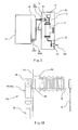
Fig. 4A is a plan view showing a connection portion between the high-voltage device box 12 and the high-voltage cable 70 according to the present embodiment.Fig. 4B is a side view showing the connection portion between the high-voltage device box 12 and the high-voltage cable 70 according to the present embodiment. Afirst connector device 51a at the high-voltage device box 12 side is mainly constituted by: abase portion 54 made of a hard insulating material, such as epoxy resin; ajoint connector portion 55a connected to thebase portion 54 and made of a hard insulating material, such as epoxy resin; and aninternal conductor 56a embedded in thebase portion 54 and thejoint connector portion 55a. Thejoint connector portion 55a has a convex shape formed in a tapered column shape and fits in a below-describedcable connector portion 72. Thebase portion 54 penetrates through a throughhole 59a of anattachment plate 58a, and an outer surface of thebase portion 54 and the throughhole 59a tightly contact each other. Further, thebase portion 54 is fitted in aninsulator 19. Theattachment plate 58a is fixed to a high-voltage devicebox dividing wall 12a by bolts and the like. Thus, thebase portion 54 is fixed at an outside of the high-voltage device box 12, and theinsulator 19 is fixed at an inside of the high-voltage device box 12. Thejoint connector portion 55a projects downward from thebase portion 54. Theinternal conductor 56a is exposed at a tip end of thejoint connector portion 55a, and aninternal thread 57 is formed at an exposed tip end portion of theinternal conductor 56a. Theinternal conductor 56a is bent at a substantially right angle in thebase portion 54 to be inserted into theinsulator 19. Thejoint connector portion 55a of thefirst connector device 51a of the present embodiment projects downward from thebase portion 54. However, the direction in which thejoint connector portion 55a projects is not especially limited. Thejoint connector portion 55a may project upward or in a horizontal direction from thebase portion 54 depending on the layout of the devices. Theinsulator 19 is fixed to the inside of the high-voltage device box 12 but may be fixed to the outside of the high-voltage device box 12. -
Fig. 5 is a side view showing the vicinity of the joint connector portion at the main transformer side according to the present embodiment. Asecond connector device 51b at themain transformer 20 side is mainly constituted by: abushing portion 60 made of a hard insulating material, such as epoxy resin; a convexjoint connector portion 55b formed integrally with thebushing portion 60; and aninternal conductor 56b embedded in thebushing portion 60 and thejoint connector portion 55b. Thejoint connector portion 55b is the same in configuration as thejoint connector portion 55a. Thebushing portion 60 penetrates through a throughhole 59b of anattachment plate 58b, and an outer surface of thebushing portion 60 and the throughhole 59b tightly contact each other. By fixing theattachment plate 58b to a maintransformer dividing wall 20a by bolts and the like, thejoint connector portion 55b is fixed at an outside of themain transformer 20, and thebushing portion 60 is fixed at an inside of themain transformer 20. Thejoint connector portion 55b projects downward from the maintransformer dividing wall 20a. Theinternal conductor 56b is exposed at a tip end of thejoint connector portion 55b, and theinternal thread 57 is formed at an exposed tip end portion of theinternal conductor 56b. Theinternal conductor 56b is inserted through thejoint connector portion 55b and thebushing portion 60 to be connected to an inner portion of themain transformer 20. Thesecond connector device 51 b of the present embodiment is fixed to the maintransformer dividing wall 20a such that thejoint connector portion 55b projects downward. However, as with thejoint connector portion 55a, the direction in which thejoint connector portion 55b projects is not especially limited. - The high-
voltage cable 70 is a member which connects thecircuit breaker 13 in the high-voltage device box 12 and themain transformer 20 and through which a high-voltage current flows. As shown inFigs. 6 and 7 , the high-voltage cable 70 is mainly constituted by a cablemain body 71 and thecable connector portion 72 provided at a tip end portion of the cablemain body 71. Regarding the high-voltage cable 70 and thepower cable 270 used in therailcar 100, the cablemain body 71 has an outer diameter of about 50 to 60 mm and is covered with a coating such that even when a high-voltage current flows through the cablemain body 71, the cablemain body 71 is insulated. Thecable connector portion 72 includes a concaveaccommodating portion 73 so as to accommodate ajoint connector portion 55. - The following will explain the
cable connector portion 72 in more detail. Thecable connector portion 72 is mainly constituted by ahousing portion 74, a connectingterminal 75, acap portion 76, and an insulatingplug 84. Thehousing portion 74 includes: a cylindrical fittubular portion 77a ; a cylindricalbase tubular portion 78 perpendicularly coupled to a side surface of the fittubular portion 77a such that an inner portion of the basetubular portion 78 and an inner portion of the fittubular portion 77a communicate with each other; and a work tubular portion 77b substantially perpendicular to the basetubular portion 78 and projecting in an opposite direction of the fittubular portion 77a on the substantially same straight line as the fittubular portion 77a. Theentire housing portion 74 is formed in a T shape. One end of the fittubular portion 77a constitutes aconnector opening portion 79 into which thejoint connector portion 55 is inserted. Theconnector opening portion 79 and its periphery constitute the concaveaccommodating portion 73. Awork opening portion 80 that is open at an opposite side of theconnector opening portion 79 is formed at the work tubular portion 77b. Further, the cablemain body 71 whose tip end portion is stepwisely stripped in advance is inserted through the basetubular portion 78 toward the inner portion of thehousing portion 74. The connectingterminal 75 is attached to the tip end of the cablemain body 71. Thehousing portion 74 is made of an elastic insulating material, such as ethylene propylene rubber (EP rubber) or silicone rubber. Although not shown, an inner semi-conducting layer is formed at an inner periphery side of a middle portion of thehousing portion 74 so as to cover the vicinity of the connectingterminal 75 and include an inner periphery side that is exposed. An outer semi-conducting layer is formed at an outer periphery of thehousing portion 74. - The inner semi-conducting layer and the outer semi-conducting layer are formed integrally with the
housing portion 74. The inner semi-conducting layer is made of semi-conducting ethylene propylene rubber (EP rubber) or semi-conducting silicone rubber, and the outer semi-conducting layer is made of semi-conducting or conductive paint, semi-conducting ethylene propylene rubber (EP rubber), or semi-conducting silicone rubber. The connectingterminal 75 is joined to acable conductor 81 of the cablemain body 71 by compression and is located in the housing portion 74 (fittubular portion 77a). The compressed portion of the connectingterminal 75 is formed in a circular shape, and a tip end portion thereof is formed in a plate shape. The insulatingplug 84 includes: an insulating plugmain body 84a made of a hard insulating material, such as epoxy resin; a fixing embedded metal fitting 84b provided at a tip end side of the insulating plugmain body 84a and embedded in the insulating plugmain body 84a such that a tip end surface thereof is exposed; and a work embedded metal fitting 84c provided at a rear end side of the insulating plugmain body 84a (at a side to which thecap portion 76 is attached) and embedded in the insulating plugmain body 84a such that a rear end portion thereof is exposed. A groove that accommodates anut member 83 and theinternal thread 57 for fixing anexternal thread member 82 are formed at a tip end portion of the fixing embedded metal fitting 84b. After the insulatingplug 84 is fitted in thework opening portion 80 of the work tubular portion 77b, thecap portion 76 is attached to close thework opening portion 80. Both thecap portion 76 and the insulatingplug 84 are detachable. Both thehousing portion 74 and thecap portion 76 are made of an elastic insulating material. The plate-shaped portion of the tip end of the connectingterminal 75 is fixed so as to be exposed at theaccommodating portion 73 of the fittubular portion 77a such that the cablemain body 71 and thecable connector portion 72 are integrated with each other. - In the embodiment, the
cable connector portion 72 is a female connector, and thejoint connector portion 55 is a male connector. However, these connectors may be reversed. The present embodiment has explained the T-shapedhousing portion 74 as thecable connector portion 72. However, an L-shaped housing which is not provided with thework opening portion 80, that is, which does not require the insulatingplug 84 may be adopted. - Next, the connection structure between the
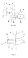
cable connector portion 72 and thefirst connector device 51a and the connection structure between thecable connector portion 72 and thesecond connector device 51b will be explained in reference toFigs. 4A to 7 . As described above, thefirst connector device 51a and thesecond connector device 51b respectively include thejoint connector portions 55 that are the same in configuration as each other. The high-voltage device box 12 is electrically connected to the high-voltage cable 70 in such a manner that theinternal conductor 56 is inserted through thejoint connector portion 55 and thebase portion 54. Themain transformer 20 is electrically connected to the high-voltage cable 70 in the same manner as above except that theinternal conductor 56 is inserted through thejoint connector portion 55 and the bushing portion (second base portion) 60. Therefore, the following will explain a method of attaching the high-voltage cable 70 and the high-voltage device box 12.Fig. 7 is an exploded view showing the vicinities of thejoint connector portion 55a and thecable connector portion 72a according to the present embodiment. - First, the
external thread member 82 is attached to thejoint connector portion 55a. Specifically, theexternal thread member 82 made of metal is threadedly engaged with theinternal thread 57 formed at the tip end portion of theinternal conductor 56 of thejoint connector portion 55a. A length of theexternal thread member 82 is larger than a depth of theinternal thread 57 formed at theinternal conductor 56. Therefore, when one end of theexternal thread member 82 is threadedly engaged with theinternal thread 57, a part of the other end of theexternal thread member 82 projects from thejoint connector portion 55a. - Next, the
cable connector portion 72a fits thejoint connector portion 55a. A direction in which thehousing portion 74 of thecable connector portion 72a fits thejoint connector portion 55a is not a longitudinal direction of the high-voltage cable 70 but a direction substantially perpendicular to the longitudinal direction of the high-voltage cable 70 (seeFig. 4B ). More specifically, thejoint connector portion 55a is accommodated in theaccommodating portion 73 of the fittubular portion 77a by covering thejoint connector portion 55a with thehousing portion 74 from a tip end of thejoint connector portion 55a. In this case, theexternal thread member 82 projecting from thejoint connector portion 55a penetrates through a through hole 75a of the connectingterminal 75 fixed in advance so as to be exposed inside theaccommodating portion 73 of the fittubular portion 77a. - Next, the
nut member 83 made of metal is inserted through thework opening portion 80 formed at the work tubular portion 77b of thehousing portion 74. In order to fix the connectingterminal 75 to theinternal conductor 56, thenut member 83 is tightened onto theexternal thread member 82 penetrating the connectingterminal 75. Then, the insulatingplug 84 is attached to the work tubular portion 77b. Since this work can be performed through thework opening portion 80, the workability is extremely high. - At last, the
cap portion 76 fits thework opening portion 80 to close thework opening portion 80. With this, the connection between the high-voltage cable 70 and thejoint connector portion 55a is completed. As above, in the connection structure between the high-voltage device box 12 and themain transformer 20 according to the present embodiment, the high-voltage cable 70 is attached to theconnector device 51 in such a manner that thecable connector portion 72 fits thejoint connector portion 55 toward the direction substantially perpendicular to the longitudinal direction of the high-voltage cable 70. - According to the configuration explained above, the distance between the high-
voltage device box 12 and themain transformer 20 can be reduced, so that a device occupation area in plan view can be reduced. Even if the changes in the relative positions of the high-voltage device box 12 and themain transformer 20 become large, the high-voltage device box 12 and themain transformer 20 can be easily, electrically connected to each other. Thus, the degree of freedom of the designs of the high-voltage device box 12 and themain transformer 20 can be improved. In consideration of the arrangement of the underfloor devices, such as themain converter 21 and the mainelectric motors 22, the high-voltage device box 12 and themain transformer 20 can be arranged so as to be separated from each other. Thus, the degree of freedom of the layout of the underfloor devices improves, so that the devices can be arranged in consideration of the weight balance. Since thehousing portions 74 of thecable connector portions 72 are the same in shape as each other, the components can be commonalized. Further, it becomes unnecessary to fix the insulatingprotective tube 6, which was necessary in conventional structures, by a plurality of bolts and the like, seal the insulatingprotective tube 6 using putty or the like, and attach and detach the connectionelectric wire 16 to and from thecircuit breaker 13. Therefore, the work of attaching and detaching the high-voltage cable 70, dust prevention work, and waterproofing work when manufacturing and maintaining the car are facilitated. - In the present embodiment, the
power cable 270 extending from on the roof and the high-voltage device box 12 are connected to each other in such a manner that: the insulatortype cable head 18 of thepower cable 270 is inserted into the high-voltage device box 12; and thepower cable 270 is electrically connected to thecircuit breaker 13 through the connectionelectric wire 15. However, a joint device having the same structure as the present embodiment may be configured. -
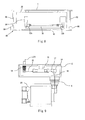
Fig. 8 is a side view showing an underfloor closing member and locking devices. Since the high-voltage device box 12 and themain transformer 20 overlap each other, the high-voltage device box 12 is not shown inFig. 8 . InFig. 8 , areference sign 90 shows the underfloor closing member that covers lower surfaces of the high-voltage device box 12, themain transformer 20, and the high-voltage cable 70. Without detaching theunderfloor closing member 90, the high-voltage cable 70 cannot be attached to or detached from the high-voltage device box 12 and themain transformer 20. Lockingdevices 99 are provided at theunderfloor closing member 90. In a case where thepower collector 11 is in a state capable of collecting power through the overhead contact line, thelocking devices 99 are in a locked state. Thelocking devices 99 can be unlocked by, for example, a tool that can be taken out from a predetermined position only when thepower collector 11 is lowered. In the present embodiment, theunderfloor closing member 90 is constituted by: alower surface member 91 that entirely covers the lower surfaces of the high-voltage device box 12, themain transformer 20, and the high-voltage cable 70; and a side surface member (fixing member) 92 that covers side surfaces of the high-voltage device box 12, themain transformer 20, and the high-voltage cable 70, and theside surface member 92 is attached to car floor structural members 1 (such as cross beams, side sills, and cross girders). However, the present embodiment is not limited to this. The present embodiment is only required to be configured such that in a case where thelocking devices 99 are unlocked, and theunderfloor closing member 90 is detached, the high-voltage cable 70 can be attached to and detached from the high-voltage device box 12 and themain transformer 20. Therefore, theside surface member 92 may be attached to the high-voltage device box 12 and themain transformer 20, and/or thelower surface member 91 may be directly attached to the high-voltage device box 12 and themain transformer 20. Thelower surface member 91 and theside surface member 92 may be constituted by mesh members, angle bars, or the like instead of the plate-shaped members. - According to the configuration explained above, electric shock accidents when attaching and detaching the high-
voltage cable 70 can be prevented. In addition, the damages of the high-voltage cable 70 by flying stones when the car travels can be prevented. - The connection structure between the main transformer and the high-voltage device box in the railcar according to the present invention is suitable for not only high-speed railcars, such as Shinkansen (registered trademark in Japan), but also various railcars including the main transformer and the high-voltage device box. Since the high-voltage device box and the main transformer can be efficiently connected to each other in a limited space under the floor of the railcar, the present invention has an excellent effect of being able to improve the degree of freedom of the layout of the underfloor devices. Therefore, it is useful to widely apply the present invention to railcars that can utilize the significance of the above effect.
-
- 6
- insulating protective tube
- 11
- power collector
- 12
- high-voltage device box
- 13
- circuit breaker
- 14
- arrester (lightning arrester)
- 20
- main transformer
- 51a
- first connector device
- 51b
- second connector device
- 54
- base portion (first base portion)
- 55, 55a, 55b
- joint connector portion
- 56a, 56b
- internal conductor
- 60
- bushing portion (second base portion)
- 70
- high-voltage cable
- 72, 72a
- cable connector portion
- 73
- accommodating portion
- 74
- housing portion
- 75
- connecting terminal
- 76
- cap portion
- 77a
- fit tubular portion
- 77b
- work tubular portion
- 78
- base tubular portion
- 80
- work opening portion
- 81
- cable conductor
- 84
- insulating plug
- 90
- underfloor closing member
- 91
- lower surface member
- 92
- side surface member (fixing member)
- 99
- locking device
- 100
- railcar
- 101 to 106
- car
Claims (5)
- A connection structure between a main transformer and a high-voltage device box,
the connection structure comprising:a circuit breaker connected to a power cable through which high-voltage power is supplied, the high-voltage power being collected through an overhead contact line by a power collector provided on a roof of a car;a high-voltage device box accommodating the circuit breaker and provided under a floor of the car;a main transformer configured to transform a voltage of the high-voltage power and provided under the floor of the car;a first connector device electrically connected to the circuit breaker and provided at a dividing wall of the high-voltage device box;a second connector device electrically connected to the main transformer and provided at a dividing wall of the main transformer; anda high-voltage cable covered with an insulating coating and having both end portions to which cable connector portions are respectively attached, whereinthe high-voltage cable connects the first connector device and the second connector device in such a manner that the cable connector portions respectively fit and are connected to the first connector device and the second connector device. - The connection structure according to claim 1, wherein:the first connector device includesa first base portion electrically connected to the circuit breaker,a first joint connector portion projecting from the first base portion, anda first conductor embedded in the first base portion and the first joint connector portion and including a tip end exposed from the first joint connector portion;the second connector device includesa second base portion electrically connected to the main transformer,a second joint connector portion projecting from the second base portion, anda second conductor embedded in the second base portion and the second joint connector portion and including a tip end exposed from the second joint connector portion;the cable connector portions respectively include housing portions;each of the housing portions includesa fit tubular portion including a fit opening whose fit direction is a direction substantially perpendicular to a longitudinal direction of the high-voltage cable, anda base tubular portion which is continuous with the fit tubular portion so as to be substantially perpendicular to the fit tubular portion and into which a tip end portion of the high-voltage cable is inserted; andin a state where the fit tubular portions respectively fit the first joint connector portion and the second joint connector portion, the first conductor and the second conductor are respectively connected to connecting terminals respectively provided at both end portions of the high-voltage cable.
- The connection structure according to claim 2, wherein:each of the cable connector portions includes a work tubular portion provided so as to be substantially perpendicular to the base tubular portion and projecting in an opposite direction of the fit tubular portion on a substantially same straight line as the fit tubular portion;the work tubular portion is provided with a work opening communicating with a connection portion between the conductor and the connecting terminal; andan insulating plug is attached to the work opening.
- The connection structure according to any one of claims 1 to 3, further comprising:a lower surface member configured to cover the high-voltage device box, the main transformer, and at least a part of the high-voltage cable from below; anda fixing member configured to fix the lower surface member to a car floor structural member or a car underfloor device, whereinat least one of the lower surface member and the fixing member includes a locking device configured to become a locked state when the power collector is in a state capable of collecting power through the overhead contact line.
- A railcar comprising the connection structure according to any one of claims 1 to 4.
Applications Claiming Priority (2)
| Application Number | Priority Date | Filing Date | Title |
|---|---|---|---|
| JP2012157457A JP5883736B2 (en) | 2012-07-13 | 2012-07-13 | Main transformer and high-voltage equipment box connection structure and railcar equipped with the connection structure |
| PCT/JP2013/004265 WO2014010240A1 (en) | 2012-07-13 | 2013-07-10 | Connecting structure of main transformer and high-voltage device box, and railroad vehicle comprising said structure |
Publications (2)
| Publication Number | Publication Date |
|---|---|
| EP2873549A1 true EP2873549A1 (en) | 2015-05-20 |
| EP2873549A4 EP2873549A4 (en) | 2016-06-29 |
Family
ID=49915721
Family Applications (1)
| Application Number | Title | Priority Date | Filing Date |
|---|---|---|---|
| EP13816265.6A Withdrawn EP2873549A4 (en) | 2012-07-13 | 2013-07-10 | MAIN TRANSFORMER CONNECTION STRUCTURE AND HIGH VOLTAGE DEVICE BOX, AND RAILWAY VEHICLE COMPRISING SAID STRUCTURE |
Country Status (7)
| Country | Link |
|---|---|
| US (1) | US9831644B2 (en) |
| EP (1) | EP2873549A4 (en) |
| JP (1) | JP5883736B2 (en) |
| CN (1) | CN104349930B (en) |
| HK (1) | HK1205069A1 (en) |
| TW (1) | TWI534024B (en) |
| WO (1) | WO2014010240A1 (en) |
Cited By (2)
| Publication number | Priority date | Publication date | Assignee | Title |
|---|---|---|---|---|
| WO2019138383A1 (en) * | 2018-01-15 | 2019-07-18 | Sécheron Sa | Electrical switching device |
| FR3082697A1 (en) * | 2018-06-19 | 2019-12-20 | Sncf Mobilites | SYSTEM FOR PROTECTING CEILING-MOUNTED ELECTRICAL POWER EQUIPMENT OF A RAIL VEHICLE |
Families Citing this family (11)
| Publication number | Priority date | Publication date | Assignee | Title |
|---|---|---|---|---|
| DE102013226356A1 (en) * | 2013-10-02 | 2015-04-02 | Scania Cv Ab | vehicle |
| WO2017141422A1 (en) | 2016-02-19 | 2017-08-24 | 三菱電機株式会社 | Power conversion device |
| CN106004448B (en) * | 2016-05-18 | 2019-02-26 | 福开尔(西安)电气有限公司 | A kind of electric locomotive high tension loop is isolated and double main disconnected redundant circuit systems naturally |
| CN106159767A (en) * | 2016-08-10 | 2016-11-23 | 国网浙江东阳市供电公司 | Modified model 10kV American Unit Substation with simple eye through hole |
| CN106159678A (en) * | 2016-08-10 | 2016-11-23 | 国网浙江东阳市供电公司 | Modified model 10kV American Unit Substation with eyes through hole |
| CN106159768A (en) * | 2016-08-10 | 2016-11-23 | 国网浙江东阳市供电公司 | Modified model 10kV American Unit Substation with simple eye through hole and protective cover |
| CN106207820A (en) * | 2016-08-10 | 2016-12-07 | 国网浙江东阳市供电公司 | Modified model 10kV American Unit Substation with eyes through hole and protective cover |
| CN112909783B (en) * | 2021-01-22 | 2022-11-08 | 袁国胜 | Installation mechanism of switch board |
| WO2023042250A1 (en) * | 2021-09-14 | 2023-03-23 | 川崎車両株式会社 | Lightning arrester monitoring device and railway vehicle provided with same |
| JP7395068B1 (en) * | 2022-05-10 | 2023-12-08 | 三菱電機株式会社 | solid insulated busbar |
| US20250368049A1 (en) * | 2022-05-23 | 2025-12-04 | Kawasaki Railcar Manufacturing Co., Ltd. | Train set |
Family Cites Families (30)
| Publication number | Priority date | Publication date | Assignee | Title |
|---|---|---|---|---|
| US3861777A (en) * | 1973-09-20 | 1975-01-21 | Permali Inc | Separable electrical connector |
| JPS5929351A (en) | 1982-08-11 | 1984-02-16 | Hitachi Ltd | Bulb type fluorescent lamp |
| JPS5929351U (en) | 1982-08-20 | 1984-02-23 | 財団法人鉄道総合技術研究所 | Air insulation protection tube for high voltage circuits |
| JPS5996368A (en) * | 1982-11-22 | 1984-06-02 | 株式会社日立製作所 | Interlock lock mechanism |
| JPS6360378A (en) * | 1986-08-29 | 1988-03-16 | 株式会社日立製作所 | Interlock device for hinged doors |
| US4799895A (en) * | 1987-06-22 | 1989-01-24 | Amerace Corporation | 600-Amp hot stick operable screw-assembled connector system |
| US5171159A (en) * | 1990-08-22 | 1992-12-15 | Byrne Norman R | Electrical interconnection assembly |
| US5114357A (en) | 1991-04-29 | 1992-05-19 | Amerace Corporation | High voltage elbow |
| KR960013032B1 (en) * | 1992-01-17 | 1996-09-25 | 미쯔비시 덴끼 가부시기가이샤 | Device for cooling transformer mounted on electric vehicle |
| JPH05258966A (en) * | 1992-03-11 | 1993-10-08 | Takaoka Electric Mfg Co Ltd | Method of connecting ground transformer to switch |
| US5766517A (en) * | 1995-12-21 | 1998-06-16 | Cooper Industries, Inc. | Dielectric fluid for use in power distribution equipment |
| JPH09232019A (en) * | 1996-02-22 | 1997-09-05 | Unisia Jecs Corp | Connection terminal for wiring |
| US5675194A (en) * | 1996-06-07 | 1997-10-07 | Walker Systems, Inc. | Modular power distribution system |
| US6775593B1 (en) * | 1999-09-21 | 2004-08-10 | Philip A. Parker | Service panel with utility controller |
| FR2822764B1 (en) * | 2001-03-29 | 2003-05-16 | Alstom | METHOD AND DEVICE FOR CONTROLLING THE POWER SUPPLY OF AN ELECTRICALLY DRIVEN VEHICLE FOR OPERATION IN EXTERNAL POWER SUPPLY MODE OR IN AUTONOMOUS POWER SUPPLY MODE |
| US7104823B2 (en) * | 2002-05-16 | 2006-09-12 | Homac Mfg. Company | Enhanced separable connector with thermoplastic member and related methods |
| US6634303B1 (en) * | 2002-06-11 | 2003-10-21 | General Motors Corporation | Locomotive wheel slip control and method |
| US7245473B2 (en) * | 2003-09-30 | 2007-07-17 | Prelec Michael L | Switchable lightning arrester system |
| GB2441466B (en) * | 2005-05-24 | 2009-12-09 | Boston Retail Products Inc | System and method for distribution of electrical power |
| MXPA06014816A (en) * | 2005-12-21 | 2008-10-16 | Thomas & Betts Int | Separable electrical connector component having a voltage output branch and a direct access point . |
| US20080231289A1 (en) * | 2007-03-19 | 2008-09-25 | General Electric Company | Clamping apparatus and a system and method for detecting defects in electrical wiring |
| US7661979B2 (en) * | 2007-06-01 | 2010-02-16 | Cooper Technologies Company | Jacket sleeve with grippable tabs for a cable connector |
| JP2009029276A (en) * | 2007-07-27 | 2009-02-12 | Toyota Motor Corp | High voltage device storage box and vehicle equipped with the same |
| JP5311972B2 (en) * | 2007-11-09 | 2013-10-09 | 株式会社日立製作所 | Formation vehicle |
| US8109776B2 (en) * | 2008-02-27 | 2012-02-07 | Cooper Technologies Company | Two-material separable insulated connector |
| US7958631B2 (en) * | 2008-04-11 | 2011-06-14 | Cooper Technologies Company | Method of using an extender for a separable insulated connector |
| US20100038228A1 (en) * | 2008-08-12 | 2010-02-18 | H-J International, Inc. | Stand-Alone Circuit Breaker Assembly and Associated Method of Use |
| BRPI0823126A2 (en) * | 2008-10-10 | 2015-06-16 | Mitsubishi Electric Corp | Vehicle control device. |
| JP5801999B2 (en) * | 2010-08-24 | 2015-10-28 | 株式会社日立製作所 | Train trains equipped with railway on-board electrical equipment |
| US8618691B2 (en) * | 2011-02-23 | 2013-12-31 | Coastal Source, LLC | Landscape electrical component connector system |
-
2012
- 2012-07-13 JP JP2012157457A patent/JP5883736B2/en active Active
-
2013
- 2013-07-10 US US14/414,545 patent/US9831644B2/en active Active
- 2013-07-10 HK HK15105641.5A patent/HK1205069A1/en unknown
- 2013-07-10 EP EP13816265.6A patent/EP2873549A4/en not_active Withdrawn
- 2013-07-10 WO PCT/JP2013/004265 patent/WO2014010240A1/en not_active Ceased
- 2013-07-10 CN CN201380030744.1A patent/CN104349930B/en active Active
- 2013-07-11 TW TW102124877A patent/TWI534024B/en active
Cited By (2)
| Publication number | Priority date | Publication date | Assignee | Title |
|---|---|---|---|---|
| WO2019138383A1 (en) * | 2018-01-15 | 2019-07-18 | Sécheron Sa | Electrical switching device |
| FR3082697A1 (en) * | 2018-06-19 | 2019-12-20 | Sncf Mobilites | SYSTEM FOR PROTECTING CEILING-MOUNTED ELECTRICAL POWER EQUIPMENT OF A RAIL VEHICLE |
Also Published As
| Publication number | Publication date |
|---|---|
| US9831644B2 (en) | 2017-11-28 |
| EP2873549A4 (en) | 2016-06-29 |
| JP2014019208A (en) | 2014-02-03 |
| CN104349930A (en) | 2015-02-11 |
| JP5883736B2 (en) | 2016-03-15 |
| US20150171604A1 (en) | 2015-06-18 |
| WO2014010240A1 (en) | 2014-01-16 |
| TWI534024B (en) | 2016-05-21 |
| CN104349930B (en) | 2017-02-22 |
| HK1205069A1 (en) | 2015-12-11 |
| TW201408519A (en) | 2014-03-01 |
Similar Documents
| Publication | Publication Date | Title |
|---|---|---|
| US9831644B2 (en) | Connection structure between main transformer and high-voltage device box and railcar including same | |
| JP5486695B2 (en) | Circuit breaker unit and railway vehicle equipped with the same | |
| US9225075B2 (en) | High voltage device system of railcar and railcar | |
| JP5571824B2 (en) | High voltage circuit breaker | |
| CN118977748A (en) | High Voltage Interconnection Systems | |
| JP6713940B2 (en) | Radiator for solid insulated switchgear unit, solid insulated switchgear unit, and railway vehicle | |
| CN113540848A (en) | cable connection | |
| CN212277849U (en) | Sealing structure of junction box of traction reactor box | |
| EP3459784A1 (en) | Branching unit and vehicular system | |
| CN112736713A (en) | Vehicle-mounted high-voltage electric box | |
| JP3392919B2 (en) | High-voltage equipment for electric traction railway vehicles | |
| JP6496638B2 (en) | Mobile substation | |
| JP5701527B2 (en) | Electric vehicle | |
| CN213109308U (en) | Protection mechanism and matching device for insulating parts between door sill connector and platform | |
| CN215070471U (en) | Closure for a cable connection device | |
| US20250368049A1 (en) | Train set | |
| KR200243197Y1 (en) | Flat insulator for electric railway | |
| JP2024064257A (en) | Noise current leakage prevention structure, noise current leakage prevention method, and electric railway vehicle | |
| HK1185590B (en) | Circuit breaker unit, and rolling stock provided therewith | |
| JPH0140567B2 (en) |
Legal Events
| Date | Code | Title | Description |
|---|---|---|---|
| PUAI | Public reference made under article 153(3) epc to a published international application that has entered the european phase |
Free format text: ORIGINAL CODE: 0009012 |
|
| 17P | Request for examination filed |
Effective date: 20150212 |
|
| AK | Designated contracting states |
Kind code of ref document: A1 Designated state(s): AL AT BE BG CH CY CZ DE DK EE ES FI FR GB GR HR HU IE IS IT LI LT LU LV MC MK MT NL NO PL PT RO RS SE SI SK SM TR |
|
| AX | Request for extension of the european patent |
Extension state: BA ME |
|
| DAX | Request for extension of the european patent (deleted) | ||
| RA4 | Supplementary search report drawn up and despatched (corrected) |
Effective date: 20160601 |
|
| RIC1 | Information provided on ipc code assigned before grant |
Ipc: H02B 13/00 20060101ALN20160526BHEP Ipc: H01R 4/56 20060101ALN20160526BHEP Ipc: B60L 3/04 20060101ALI20160526BHEP Ipc: B60L 3/00 20060101ALI20160526BHEP Ipc: B60L 9/24 20060101AFI20160526BHEP Ipc: B60C 3/00 20060101ALI20160526BHEP Ipc: B61C 3/00 20060101ALI20160526BHEP Ipc: H02G 15/02 20060101ALI20160526BHEP Ipc: H02B 1/46 20060101ALN20160526BHEP Ipc: H01R 24/00 20110101ALI20160526BHEP Ipc: H02G 15/08 20060101ALI20160526BHEP Ipc: H02G 15/04 20060101ALN20160526BHEP Ipc: B61C 17/12 20060101ALI20160526BHEP |
|
| STAA | Information on the status of an ep patent application or granted ep patent |
Free format text: STATUS: EXAMINATION IS IN PROGRESS |
|
| 17Q | First examination report despatched |
Effective date: 20190529 |
|
| STAA | Information on the status of an ep patent application or granted ep patent |
Free format text: STATUS: THE APPLICATION IS DEEMED TO BE WITHDRAWN |
|
| 18D | Application deemed to be withdrawn |
Effective date: 20210202 |