EP2873504A1 - Fluid storage tank assembly for an off-road vehicle and method for its manufacture - Google Patents
Fluid storage tank assembly for an off-road vehicle and method for its manufacture Download PDFInfo
- Publication number
- EP2873504A1 EP2873504A1 EP20140191811 EP14191811A EP2873504A1 EP 2873504 A1 EP2873504 A1 EP 2873504A1 EP 20140191811 EP20140191811 EP 20140191811 EP 14191811 A EP14191811 A EP 14191811A EP 2873504 A1 EP2873504 A1 EP 2873504A1
- Authority
- EP
- European Patent Office
- Prior art keywords
- fill spout
- polymeric material
- support ring
- storage tank
- fluid storage
- Prior art date
- Legal status (The legal status is an assumption and is not a legal conclusion. Google has not performed a legal analysis and makes no representation as to the accuracy of the status listed.)
- Granted
Links
Images


Classifications
-
- B—PERFORMING OPERATIONS; TRANSPORTING
- B29—WORKING OF PLASTICS; WORKING OF SUBSTANCES IN A PLASTIC STATE IN GENERAL
- B29C—SHAPING OR JOINING OF PLASTICS; SHAPING OF MATERIAL IN A PLASTIC STATE, NOT OTHERWISE PROVIDED FOR; AFTER-TREATMENT OF THE SHAPED PRODUCTS, e.g. REPAIRING
- B29C41/00—Shaping by coating a mould, core or other substrate, i.e. by depositing material and stripping-off the shaped article; Apparatus therefor
- B29C41/02—Shaping by coating a mould, core or other substrate, i.e. by depositing material and stripping-off the shaped article; Apparatus therefor for making articles of definite length, i.e. discrete articles
- B29C41/04—Rotational or centrifugal casting, i.e. coating the inside of a mould by rotating the mould
-
- F—MECHANICAL ENGINEERING; LIGHTING; HEATING; WEAPONS; BLASTING
- F01—MACHINES OR ENGINES IN GENERAL; ENGINE PLANTS IN GENERAL; STEAM ENGINES
- F01N—GAS-FLOW SILENCERS OR EXHAUST APPARATUS FOR MACHINES OR ENGINES IN GENERAL; GAS-FLOW SILENCERS OR EXHAUST APPARATUS FOR INTERNAL-COMBUSTION ENGINES
- F01N3/00—Exhaust or silencing apparatus having means for purifying, rendering innocuous, or otherwise treating exhaust
- F01N3/08—Exhaust or silencing apparatus having means for purifying, rendering innocuous, or otherwise treating exhaust for rendering innocuous
- F01N3/10—Exhaust or silencing apparatus having means for purifying, rendering innocuous, or otherwise treating exhaust for rendering innocuous by thermal or catalytic conversion of noxious components of exhaust
- F01N3/103—Oxidation catalysts for HC and CO only
-
- B—PERFORMING OPERATIONS; TRANSPORTING
- B29—WORKING OF PLASTICS; WORKING OF SUBSTANCES IN A PLASTIC STATE IN GENERAL
- B29C—SHAPING OR JOINING OF PLASTICS; SHAPING OF MATERIAL IN A PLASTIC STATE, NOT OTHERWISE PROVIDED FOR; AFTER-TREATMENT OF THE SHAPED PRODUCTS, e.g. REPAIRING
- B29C41/00—Shaping by coating a mould, core or other substrate, i.e. by depositing material and stripping-off the shaped article; Apparatus therefor
- B29C41/02—Shaping by coating a mould, core or other substrate, i.e. by depositing material and stripping-off the shaped article; Apparatus therefor for making articles of definite length, i.e. discrete articles
- B29C41/04—Rotational or centrifugal casting, i.e. coating the inside of a mould by rotating the mould
- B29C41/042—Rotational or centrifugal casting, i.e. coating the inside of a mould by rotating the mould by rotating a mould around its axis of symmetry
-
- B—PERFORMING OPERATIONS; TRANSPORTING
- B29—WORKING OF PLASTICS; WORKING OF SUBSTANCES IN A PLASTIC STATE IN GENERAL
- B29C—SHAPING OR JOINING OF PLASTICS; SHAPING OF MATERIAL IN A PLASTIC STATE, NOT OTHERWISE PROVIDED FOR; AFTER-TREATMENT OF THE SHAPED PRODUCTS, e.g. REPAIRING
- B29C41/00—Shaping by coating a mould, core or other substrate, i.e. by depositing material and stripping-off the shaped article; Apparatus therefor
- B29C41/02—Shaping by coating a mould, core or other substrate, i.e. by depositing material and stripping-off the shaped article; Apparatus therefor for making articles of definite length, i.e. discrete articles
- B29C41/20—Shaping by coating a mould, core or other substrate, i.e. by depositing material and stripping-off the shaped article; Apparatus therefor for making articles of definite length, i.e. discrete articles incorporating preformed parts or layers, e.g. moulding inserts or for coating articles
-
- B—PERFORMING OPERATIONS; TRANSPORTING
- B60—VEHICLES IN GENERAL
- B60K—ARRANGEMENT OR MOUNTING OF PROPULSION UNITS OR OF TRANSMISSIONS IN VEHICLES; ARRANGEMENT OR MOUNTING OF PLURAL DIVERSE PRIME-MOVERS IN VEHICLES; AUXILIARY DRIVES FOR VEHICLES; INSTRUMENTATION OR DASHBOARDS FOR VEHICLES; ARRANGEMENTS IN CONNECTION WITH COOLING, AIR INTAKE, GAS EXHAUST OR FUEL SUPPLY OF PROPULSION UNITS IN VEHICLES
- B60K13/00—Arrangement in connection with combustion air intake or gas exhaust of propulsion units
- B60K13/04—Arrangement in connection with combustion air intake or gas exhaust of propulsion units concerning exhaust
-
- B—PERFORMING OPERATIONS; TRANSPORTING
- B65—CONVEYING; PACKING; STORING; HANDLING THIN OR FILAMENTARY MATERIAL
- B65D—CONTAINERS FOR STORAGE OR TRANSPORT OF ARTICLES OR MATERIALS, e.g. BAGS, BARRELS, BOTTLES, BOXES, CANS, CARTONS, CRATES, DRUMS, JARS, TANKS, HOPPERS, FORWARDING CONTAINERS; ACCESSORIES, CLOSURES, OR FITTINGS THEREFOR; PACKAGING ELEMENTS; PACKAGES
- B65D25/00—Details of other kinds or types of rigid or semi-rigid containers
- B65D25/38—Devices for discharging contents
- B65D25/40—Nozzles or spouts
- B65D25/42—Integral or attached nozzles or spouts
-
- F—MECHANICAL ENGINEERING; LIGHTING; HEATING; WEAPONS; BLASTING
- F01—MACHINES OR ENGINES IN GENERAL; ENGINE PLANTS IN GENERAL; STEAM ENGINES
- F01N—GAS-FLOW SILENCERS OR EXHAUST APPARATUS FOR MACHINES OR ENGINES IN GENERAL; GAS-FLOW SILENCERS OR EXHAUST APPARATUS FOR INTERNAL-COMBUSTION ENGINES
- F01N13/00—Exhaust or silencing apparatus characterised by constructional features
-
- B—PERFORMING OPERATIONS; TRANSPORTING
- B29—WORKING OF PLASTICS; WORKING OF SUBSTANCES IN A PLASTIC STATE IN GENERAL
- B29K—INDEXING SCHEME ASSOCIATED WITH SUBCLASSES B29B, B29C OR B29D, RELATING TO MOULDING MATERIALS OR TO MATERIALS FOR MOULDS, REINFORCEMENTS, FILLERS OR PREFORMED PARTS, e.g. INSERTS
- B29K2705/00—Use of metals, their alloys or their compounds, for preformed parts, e.g. for inserts
- B29K2705/08—Transition metals
- B29K2705/12—Iron
-
- B—PERFORMING OPERATIONS; TRANSPORTING
- B29—WORKING OF PLASTICS; WORKING OF SUBSTANCES IN A PLASTIC STATE IN GENERAL
- B29L—INDEXING SCHEME ASSOCIATED WITH SUBCLASS B29C, RELATING TO PARTICULAR ARTICLES
- B29L2031/00—Other particular articles
- B29L2031/712—Containers; Packaging elements or accessories, Packages
- B29L2031/7172—Fuel tanks, jerry cans
-
- B—PERFORMING OPERATIONS; TRANSPORTING
- B60—VEHICLES IN GENERAL
- B60K—ARRANGEMENT OR MOUNTING OF PROPULSION UNITS OR OF TRANSMISSIONS IN VEHICLES; ARRANGEMENT OR MOUNTING OF PLURAL DIVERSE PRIME-MOVERS IN VEHICLES; AUXILIARY DRIVES FOR VEHICLES; INSTRUMENTATION OR DASHBOARDS FOR VEHICLES; ARRANGEMENTS IN CONNECTION WITH COOLING, AIR INTAKE, GAS EXHAUST OR FUEL SUPPLY OF PROPULSION UNITS IN VEHICLES
- B60K15/00—Arrangement in connection with fuel supply of combustion engines or other fuel consuming energy converters, e.g. fuel cells; Mounting or construction of fuel tanks
- B60K15/03—Fuel tanks
- B60K15/04—Tank inlets
-
- B—PERFORMING OPERATIONS; TRANSPORTING
- B60—VEHICLES IN GENERAL
- B60K—ARRANGEMENT OR MOUNTING OF PROPULSION UNITS OR OF TRANSMISSIONS IN VEHICLES; ARRANGEMENT OR MOUNTING OF PLURAL DIVERSE PRIME-MOVERS IN VEHICLES; AUXILIARY DRIVES FOR VEHICLES; INSTRUMENTATION OR DASHBOARDS FOR VEHICLES; ARRANGEMENTS IN CONNECTION WITH COOLING, AIR INTAKE, GAS EXHAUST OR FUEL SUPPLY OF PROPULSION UNITS IN VEHICLES
- B60K15/00—Arrangement in connection with fuel supply of combustion engines or other fuel consuming energy converters, e.g. fuel cells; Mounting or construction of fuel tanks
- B60K15/03—Fuel tanks
- B60K2015/03032—Manufacturing of fuel tanks
-
- B—PERFORMING OPERATIONS; TRANSPORTING
- B60—VEHICLES IN GENERAL
- B60K—ARRANGEMENT OR MOUNTING OF PROPULSION UNITS OR OF TRANSMISSIONS IN VEHICLES; ARRANGEMENT OR MOUNTING OF PLURAL DIVERSE PRIME-MOVERS IN VEHICLES; AUXILIARY DRIVES FOR VEHICLES; INSTRUMENTATION OR DASHBOARDS FOR VEHICLES; ARRANGEMENTS IN CONNECTION WITH COOLING, AIR INTAKE, GAS EXHAUST OR FUEL SUPPLY OF PROPULSION UNITS IN VEHICLES
- B60K15/00—Arrangement in connection with fuel supply of combustion engines or other fuel consuming energy converters, e.g. fuel cells; Mounting or construction of fuel tanks
- B60K15/03—Fuel tanks
- B60K15/04—Tank inlets
- B60K2015/0458—Details of the tank inlet
-
- B—PERFORMING OPERATIONS; TRANSPORTING
- B60—VEHICLES IN GENERAL
- B60Y—INDEXING SCHEME RELATING TO ASPECTS CROSS-CUTTING VEHICLE TECHNOLOGY
- B60Y2200/00—Type of vehicle
- B60Y2200/20—Off-Road Vehicles
- B60Y2200/22—Agricultural vehicles
-
- B—PERFORMING OPERATIONS; TRANSPORTING
- B60—VEHICLES IN GENERAL
- B60Y—INDEXING SCHEME RELATING TO ASPECTS CROSS-CUTTING VEHICLE TECHNOLOGY
- B60Y2200/00—Type of vehicle
- B60Y2200/20—Off-Road Vehicles
- B60Y2200/22—Agricultural vehicles
- B60Y2200/221—Tractors
-
- B—PERFORMING OPERATIONS; TRANSPORTING
- B60—VEHICLES IN GENERAL
- B60Y—INDEXING SCHEME RELATING TO ASPECTS CROSS-CUTTING VEHICLE TECHNOLOGY
- B60Y2200/00—Type of vehicle
- B60Y2200/40—Special vehicles
- B60Y2200/41—Construction vehicles, e.g. graders, excavators
-
- F—MECHANICAL ENGINEERING; LIGHTING; HEATING; WEAPONS; BLASTING
- F01—MACHINES OR ENGINES IN GENERAL; ENGINE PLANTS IN GENERAL; STEAM ENGINES
- F01N—GAS-FLOW SILENCERS OR EXHAUST APPARATUS FOR MACHINES OR ENGINES IN GENERAL; GAS-FLOW SILENCERS OR EXHAUST APPARATUS FOR INTERNAL-COMBUSTION ENGINES
- F01N2240/00—Combination or association of two or more different exhaust treating devices, or of at least one such device with an auxiliary device, not covered by indexing codes F01N2230/00 or F01N2250/00, one of the devices being
- F01N2240/04—Combination or association of two or more different exhaust treating devices, or of at least one such device with an auxiliary device, not covered by indexing codes F01N2230/00 or F01N2250/00, one of the devices being an electric, e.g. electrostatic, device other than a heater
-
- F—MECHANICAL ENGINEERING; LIGHTING; HEATING; WEAPONS; BLASTING
- F01—MACHINES OR ENGINES IN GENERAL; ENGINE PLANTS IN GENERAL; STEAM ENGINES
- F01N—GAS-FLOW SILENCERS OR EXHAUST APPARATUS FOR MACHINES OR ENGINES IN GENERAL; GAS-FLOW SILENCERS OR EXHAUST APPARATUS FOR INTERNAL-COMBUSTION ENGINES
- F01N2610/00—Adding substances to exhaust gases
- F01N2610/14—Arrangements for the supply of substances, e.g. conduits
- F01N2610/1406—Storage means for substances, e.g. tanks or reservoirs
Definitions
- the present disclosure relates generally to off-road vehicles, and more particularly, to a fluid storage tank assembly for an off-road vehicle.
- Certain off-road vehicles are powered by diesel engines which produce exhaust gas.
- the exhaust gas may include undesirable byproducts, such as nitrogen oxides (NOx), carbon monoxide, and particulate material.
- vehicle exhaust systems may spray diesel exhaust fluid (DEF) from a DEF tank (e.g., fluid storage tank) into the flow of exhaust gas.
- DEF tank e.g., fluid storage tank
- a hose may be coupled to a first fill spout on the DEF tank to improve the ease with which the tank may be filled.
- the DEF tank may include a second fill spout located on a different side of the off-road vehicle from the fuel fill spout.
- the hose may be coupled to the first fill spout of the DEF tank to enable the DEF and fuel to be replenished from the same side of the off-road vehicle.
- one end of the hose may be disposed about an outer diameter of the fill spout
- a hose clamp may be disposed about an outer diameter to the hose to couple the hose to the fill spout
- the hose may be routed through the vehicle to the same side of the vehicle as the fuel fill spout.
- DEF may leak at the coupling point.
- a method for manufacturing a fluid storage tank assembly for an off-road vehicle includes disposing a support ring within a cavity of a rotational mold, in which the cavity is shaped to form a fill spout of the fluid storage tank assembly; and flowing a liquid polymeric material within the rotational mold such that the liquid polymeric material enters the cavity, directly contacts the support ring, and bonds to the support ring as the liquid polymeric material hardens.
- a fluid storage tank assembly for an off-road vehicle includes a first fill spout comprising a support, wherein the first fill spout is formed from a polymeric material in a rotational molding process, the support ring is bonded to the polymeric material during the rotational molding process, and the first fill spout is configured to couple to a hose to enable the fluid storage tank assembly to be filled from a first side of the off-road vehicle.
- a fluid storage tank assembly for an off-road vehicle manufactured by a process that includes rotating a rotational mold filled with a liquid polymeric material such that the liquid polymeric material enters a cavity configured to form a fill spout and bonds to a support ring disposed within the cavity as the liquid polymeric material harden.
- the exhaust system of some off-road vehicles may spray diesel exhaust fluid (DEF), which is stored in a DEF tank, into the exhaust to reduce such byproducts.
- DEF diesel exhaust fluid
- a DEF tank may store between 150-250 liters of DEF.
- a Steiger Tractor made by CNH Global N.V. of Amsterdam, Netherlands.
- a Steiger Tractor may have an axle width of approximately 90 inches and a wheelbase of approximately 154 inches.
- a hose may be coupled to a fill spout of the DEF tank to enable the DEF tank to be filled from a more convenient location.
- the hose may enable the DEF tank to be filled from the same side of the vehicle as the fuel tank.
- external factors such as changes in temperature, may cause the coupling between the hose and the fill spout to loosen, which may enable DEF to leak through the coupling.
- a DEF tank formed out of a polymeric material, such as thermoplastic may shrink relative to the hose in cold weather, thereby loosening the coupling.
- the polymeric material used to form the DEF tank may be relatively pliable.
- the hose may be forced into the inner diameter of the fill spout to provide structural support for the fill spout.
- the hose may be coupled to the fill spout by mechanically cleaning out the fill spout and forcing the hose or a support insert into the inner diameter of the fill spout.
- the opening of the fill spout may be partially or completely obstructed by the polymeric material (e.g., thermoplastic) used to mold the DEF tank.
- the fill spout may be unobstructed by mechanically cleaning (e.g., drilling) the opening.
- debris and/or residue is produced, which may be left within the DEF tank.
- one embodiment of the present disclosure provides a method for manufacturing a DEF tank assembly that substantially reduces or eliminates the possibility of DEF fluid leakage and/or substantially reduces or eliminates the possibility of debris collection within the DEF tank. More specifically, the method may include disposing a support ring within a cavity of a rotational mold such that the cavity is shaped to form a fill spout of the fluid storage tank assembly and flowing a liquid polymeric material within the rotational mold such that the liquid polymeric material enters the cavity, directly contacts the support ring, and bonds to the support ring as the liquid polymeric material hardens. The method may further include attaching a hose around an outer diameter of the fill spout to enable the fluid storage tank assembly to be filled with a fluid.
- the support ring which is bonded to the fill spout of the DEF tank, provides structural support for the fill spout, thereby substantially reducing or eliminating the possibility of DEF leakage.
- the support ring may reduce the amount of shrinkage of the fill spout during cold temperatures, thereby maintaining the dimensions of the fill spout.
- the support ring is bonded to the polymeric material of the fill spout during the molding process to provide a well-defined (e.g., unobstructed) opening into the DEF tank. As a result, the process of removing material from the inner surface of the fill spout is obviated.
- the techniques described herein may improve the reliability of a DEF tank.
- the present techniques are generally described in relation to a DEF tank, the techniques described herein may additionally be utilized in other storage tanks, such as fuel tanks, grain tanks, fertilizer tanks, and the like.
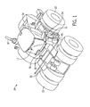
- FIG. 1 is a perspective view of an embodiment of an off-road vehicle 10 that employs a DEF tank assembly 12.
- the illustrated off-road vehicle 10 is an agricultural work vehicle.
- the off-road vehicle may be any suitable vehicle that utilizes DEF.
- the vehicle 10 also includes a body 14 that houses an engine, transmission, cooling system, and power train (not separately shown), a diesel fuel tank 15 that may be filled via a fuel fill spout 16, a cabin 17 where an operator may sit or stand to operate the vehicle 10, an exhaust pipe 18, and four front wheels 20 and four rear wheels 22 that rotate to facilitate movement of the vehicle 10.
- the vehicle 10 may have two or six front wheels 20 and/or rear wheels 22.
- the vehicle 10 may have two tracks or four tracks instead of wheels.
- the vehicle's exhaust system may spray DEF from the DEF tank 12 into an exhaust flow to reduce undesirable byproducts.
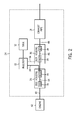
- the exhaust system 24 includes a diesel oxidation catalyst (DOC) assembly having a housing 26 containing a DOC 28 and a mixer 30.
- the exhaust system 24 also includes an injector 32 for injecting DEF 34, the DEF tank 12, a selective catalytic reduction (SCR) housing 36 containing an SCR module 38, and the exhaust pipe 18.
- the mixer 30 may be disposed within the SCR housing 36 instead of, or in addition to, the DOC housing 26.
- Certain embodiments of the exhaust system 24 may additionally include a diesel particulate filter to capture particulate matter, a muffler, or any other element suitable for use in an exhaust system.
- the DOC housing 26 receives exhaust 40 expelled by the engine 42 and directs the exhaust 40 into the DOC 28.
- the DOC 28 receives the exhaust and catalyzes the oxidization of carbon monoxide to carbon dioxide by using excess oxygen in the exhaust 40.
- the DOC 28 uses excess oxygen to catalyze the conversion of hydrocarbons to water and carbon dioxide.
- the DOC 28 may use ceramics and/or metals (e.g., platinum or palladium) to catalyze the oxidization of the hydrocarbons and carbon monoxide molecules.
- the DOC 28 receives raw exhaust 40 and outputs catalyzed exhaust 44 with reduced concentrations of hydrocarbons and carbon monoxide.
- the DOC housing 26 then directs the catalyzed exhaust 44 to the mixer 30.
- the injector 32 sprays DEF 34 from the DEF tank 12 into the exhaust 44.
- the DEF 34 is a solution used to reduce NOx within the exhaust 44.
- the DEF 34 may include an aqueous urea solution that undergoes thermal decomposition and hydrolysis within the exhaust system 24 to produce ammonia, which the SCR 38 uses to convert the NOx into nitrogen and water.
- the mixer 30 supplies a well-mixed exhaust solution 46 (e.g., a mixture of the exhaust 44 and DEF 34) to the SCR module 38.
- the SCR module 38 receives the exhaust solution 46 and uses the distributed DEF 34 to reduce the NOx concentration in the exhaust gas.
- the SCR module 38 sends processed exhaust 48 with a reduced NOx concentration through the exhaust pipe 18 to be released into the atmosphere.
- the exhaust system 24, and more specifically the DEF tank assembly 12 may also be contained within the vehicle body 14.
- portions of the body 14 that house the DEF tank assembly 12 have been removed to enable viewing of the assembly 12 within the context of the vehicle 10.
- the DEF tank assembly 12 includes a tank body 49 to store DEF, a hose 50 coupled to a first fill spout 52, and a second fill spout 54.
- portions of the DEF tank assembly 12 e.g., the tank body 49, the first fill spout 52, and/or the second fill spout 54
- rotational molding is disclosed herein, other suitable molding techniques, such as injection molding, may be utilized in alternative embodiments.
- the second fill spout 54 enables the DEF tank 12 to be filled from a first side (e.g., right side) of the vehicle 10.
- the fuel tank 15 may be filled via the fuel fill spout 16.
- the fuel fill spout is positioned on a second side (e.g., left side) of the vehicle 10.
- the hose 50 may be coupled to a second fill spout and routed through the vehicle body 14 to enable the DEF tank 12 to also be filled from the second side (e.g., left side).
- an operator may replenish both the DEF tank 12 and the fuel tank 15 from the same side of the vehicle, thereby reducing the duration associated with replenishing the DEF and fuel.
- the first fill spout 52 which is not explicitly depicted in FIG. 1 because it is blocked from view by the body 49 of the DEF tank assembly 12, is clearly depicted in FIG. 3 .
- an end of the hose 50 is disposed about the outer surface of the first fill spout 52 to enable the DEF tank assembly 12 to be filled as DEF flows from the hose 50 to the tank body 49 via the opening 55 of the first fill spout 52 (represented by arrow 56).
- the hose 50 is secured to the outer surface of the first fill spout 52 by a hose clamp 58 and/or molded ridges 60 on the outer surface of the first fill spout 52. More specifically, the hose clamp 58 provides an inward force around the outer surface of the hose 50, and the molded ridges 60 provide frictional resistance against the inner surface of the hose 50, thereby blocking movement of the hose 50 relative to the first fill spout 52. Additionally, the molded ridges 60 engage the inner surface of the hose 52 to block fluid flow from the coupling.
- a support ring 62 is bonded to the polymeric material 64 of the first fill spout 52 to provide structural support to the first fill spout 52.
- the support ring 62 may reduce deformation of the fill spout 52 under the pressure of the hose clamp 58, thereby establishing a tight seal between the outer surface of the first fill spout 52 and the inner surface of the hose 50.
- the support ring 62 may experience less variation in size (e.g., shrinkage) due to changes in the environment (e.g., cold temperatures), which may improve the reliability of the coupling between the hose 50 and the fill spout 52.
- the support ring 62 may be formed from steel, other metallic materials, or the like. As depicted, the polymeric material 64 is molded to the contours 66 of the support ring 62. In some embodiments, the support ring 62 is bonded to the first fill spout 52 during the molding process (e.g., rotational molding) of the DEF tank 12.
- the hose 50 is secured to the outer surface of the fill spout 52. Additionally or alternatively, the hose 50 may be secured within the inner diameter of the fill spout 52. That is, the inner surface of the fill spout 52 may be disposed about the outer surface of the hose 50.
- FIG. 4 One embodiment of a rotational mold 68 that may be used to form the first fill spout 52 is depicted in FIG. 4 .
- the mold 68 may be part of a larger mold used to form the entire DEF tank 12 via rotational molding.
- the mold 68 includes an outer shell 70, an inner cavity 71, and a plug 72 that extends through an opening 74 in the outer shell 70.
- the inner cavity 72 molds the outer surface of the fill spout 52.
- the walls of the inner cavity 71 e.g., inner surface of outer shell 70
- the plug 72 may hold the support ring 62 in place during molding and may facilitate forming a well-defined opening 55 in the fill spout 52.
- the support ring 62 is secured within the cavity 71 by the plug 72 while liquid polymeric material 64 (e.g., thermoplastic resin or thermosetting resin) is flowed into the mold 68.
- liquid polymeric material 64 e.g., thermoplastic resin or thermosetting resin
- the support ring 62 is secured between the plug 72 and the outer shell 70 such that the ring 62 may be molded to the distal end of the fill spout 52.
- the support ring 62 may be secured to mold 68 at a different location, thereby molding the support ring 62 another portion of the tank 12, such as an intermediate portion of the fill spout 52 or the tank body 49.
- the mold 68 is rotated (e.g., spun) to adhere the liquid polymeric material to the walls of the cavity 71, to the contours 66 of the support ring 62, and/or to the surface of the plug 72, as depicted in FIG 5 .
- the liquid polymeric material 64 that adheres to the walls of the cavity 71 e.g., inner surface of the outer shell 70
- the polymeric material 64 is molded to form the molded ridges 60.
- the support ring 62 and/or the plug 72 may be utilized to form the opening 55 of the first fill spout 52.
- the plug 72 and the support ring 62 block the polymeric material 64 from flowing into the opening 55.
- the polymeric material 64 is directed to flow around the plug 72 and the support ring 62.
- the polymeric material 64 is guided into the contours 66 of the support ring 62 and along the edges 77 of the plug 72. Accordingly, the plug 72 and the support ring 62 may establish the inner surface of the fill spout 52 by defining the opening 55.
- the mechanical cleaning e.g., machining
- the polymeric material 64 After the polymeric material 64 flows into the rotational mold (e.g., covers the cavity 71, the support ring 62, and/or the plug 72), the polymeric material 64 hardens (e.g., via a cooling process) and the DEF tank 12 is removed from the mold 68, as depicted in FIG. 6 . As described above, during the molding process, the polymeric material 64 fills the contours 66 of the support ring 62. Thus, when the polymeric material 64 hardens, the support ring 62 may be bonded (e.g., secured) to a distal end 78 of the fill spout 52. In other words, the contours 66 of the support ring 62 may provide an enhanced (e.g., stronger) bond between the polymeric material 64 and the support ring 62.
- the support ring 62 may be bonded (e.g., secured) to a distal end 78 of the fill spout 52.
- the outer shell 70 may be removed from the DEF tank 12 and the plug 72 may be extracted from the DEF tank 12.
- the plug 72 may be pulled through the opening 55.
- the plug 72 may be formed from an elastic material, such as rubber, to enable the plug 72 to be removed from the tank 12 through the opening 55.
- the plug 72 may be removed through another opening in the tank 12.
- FIG. 7 shows one embodiment of a process 79 for forming the DEF tank assembly 12.
- the process 79 begins by disposing the support ring 62 within the cavity 71 of the mold (process block 80).
- the support ring 62 may be secured in the cavity 71 between the outer shell 70 and the plug 72, such that the support ring 62 will be molded to the distal end 78 of the fill spout 52.
- Liquid polymeric material 64 is then be flowed into the mold 68 (process block 82) and the mold 68 is rotated (e.g., spun) such that the liquid polymeric material 64 enters the cavity 71 and directly contacts the support ring 62 (process block 84).
- the liquid polymeric material 64 covering the walls of the cavity 71 may form the outer surface of the fill spout 52, and the liquid polymeric material 64 may fill the contours 66 of the support ring 62 to form the opening 55.
- the support ring 62 may be bonded (e.g., secured) to the polymeric material 64 of the fill spout 52.
- the DEF tank 12 may be removed from the mold 68 (process block 88) and the hose 50 may be attached around the outer diameter of the fill spout 52 (process block 90).
- the hose 50 may be secured to the fill spout 52 through a combination of the hose clamp 58 and the molded ridges 60.
- the support ring 62 may provide structural support for the fill spout 52, which may include reducing the likelihood of the fill spout 52 collapsing under the pressure of the hose clamp 58.
- the DEF tank 12 With the hose 50 attached, the DEF tank 12 may be filled through the hose 50 (process block 92). As described above, since the opening 55 of the fill spout 52 is well-defined by the support ring 62, the amount of mechanical cleaning used to clear the fill spout 52 and the debris produced by the cleaning may be obviated.
- the technical effects of the present disclosure include improving the reliability of the DEF tank 12. More specifically, the technical effects may include substantially reducing or eliminating fluid leakage through the coupling between the hose 50 and the fill spout 52 on the DEF tank 12. In some embodiments, such technical effects results from bonding a support ring 62 to the fill spout 52 during molding of the fill spout 52 to provide structural support for the fill spout 52.
- the support ring 62 may substantially reduce or eliminate the possibility of the coupling between the fill spout 52 and the hose 50 loosening undesirably (e.g., during cold temperatures or under pressure from the hose clamp 58).
- the reliability of the DEF tank 12 may be improved by substantially reducing or eliminating the mechanical cleaning process used to define the opening 55.
- the support ring 62 may be molded into the fill spout 52 to well-define the opening 55 and provide structural support for the fill spout 52.
Landscapes
- Engineering & Computer Science (AREA)
- Mechanical Engineering (AREA)
- Chemical & Material Sciences (AREA)
- Combustion & Propulsion (AREA)
- General Engineering & Computer Science (AREA)
- Transportation (AREA)
- Materials Engineering (AREA)
- Health & Medical Sciences (AREA)
- Chemical Kinetics & Catalysis (AREA)
- Toxicology (AREA)
- Cooling, Air Intake And Gas Exhaust, And Fuel Tank Arrangements In Propulsion Units (AREA)
- Moulding By Coating Moulds (AREA)
- Injection Moulding Of Plastics Or The Like (AREA)
Abstract
Description
- The present disclosure relates generally to off-road vehicles, and more particularly, to a fluid storage tank assembly for an off-road vehicle.
- Certain off-road vehicles are powered by diesel engines which produce exhaust gas. The exhaust gas may include undesirable byproducts, such as nitrogen oxides (NOx), carbon monoxide, and particulate material. To reduce emissions of such byproducts, vehicle exhaust systems may spray diesel exhaust fluid (DEF) from a DEF tank (e.g., fluid storage tank) into the flow of exhaust gas. Because of the substantial size of some off-road vehicles (e.g., a tractor) that utilize DEF, a hose may be coupled to a first fill spout on the DEF tank to improve the ease with which the tank may be filled. More specifically, in some embodiments, the DEF tank may include a second fill spout located on a different side of the off-road vehicle from the fuel fill spout. Thus, the hose may be coupled to the first fill spout of the DEF tank to enable the DEF and fuel to be replenished from the same side of the off-road vehicle. For example, one end of the hose may be disposed about an outer diameter of the fill spout, a hose clamp may be disposed about an outer diameter to the hose to couple the hose to the fill spout, and the hose may be routed through the vehicle to the same side of the vehicle as the fuel fill spout. However, if the coupling between the hose and the DEF tank loosens, for example during cold temperatures, DEF may leak at the coupling point.
- Certain embodiments commensurate in scope with the originally claimed invention are summarized below. These embodiments are not intended to limit the scope of the claimed invention, but rather these embodiments are intended only to provide a brief summary of possible forms of the invention. Indeed, the invention may encompass a variety of forms that may be similar to or different from the embodiments set forth below.
- In a first embodiment, a method for manufacturing a fluid storage tank assembly for an off-road vehicle includes disposing a support ring within a cavity of a rotational mold, in which the cavity is shaped to form a fill spout of the fluid storage tank assembly; and flowing a liquid polymeric material within the rotational mold such that the liquid polymeric material enters the cavity, directly contacts the support ring, and bonds to the support ring as the liquid polymeric material hardens.
- In a second embodiment, a fluid storage tank assembly for an off-road vehicle, includes a first fill spout comprising a support, wherein the first fill spout is formed from a polymeric material in a rotational molding process, the support ring is bonded to the polymeric material during the rotational molding process, and the first fill spout is configured to couple to a hose to enable the fluid storage tank assembly to be filled from a first side of the off-road vehicle.
- In a third embodiment, a fluid storage tank assembly for an off-road vehicle, manufactured by a process that includes rotating a rotational mold filled with a liquid polymeric material such that the liquid polymeric material enters a cavity configured to form a fill spout and bonds to a support ring disposed within the cavity as the liquid polymeric material harden.
- These and other features, aspects, and advantages of the present invention will become better understood when the following detailed description is read with reference to the accompanying drawings in which like characters represent like parts throughout the drawings, wherein:
-
FIG. 1 is a perspective view of an embodiment of an off-road work vehicle including a DEF tank; -
FIG. 2 is a block diagram of an exhaust system that may be employed within the off-road vehicle ofFIG. 1 , in accordance with an embodiment of the present disclosure; -
FIG. 3 is a cross-sectional view of a fill spout of a DEF tank that may be employed within the work vehicle ofFIG. 1 , in accordance with an embodiment of the present disclosure; -
FIG. 4 is a cross-sectional view of a rotational mold that may be used to form the DEF tank ofFIG. 3 , in accordance with an embodiment of the present disclosure; -
FIG. 5 is a cross-sectional view of a liquid polymeric material disposed within the rotational mold ofFIG. 4 and a support ring in contact with the liquid polymeric material, in accordance with an embodiment of the present disclosure; -
FIG. 6 is a cross-sectional view of a resulting DEF tank formed by the rotational mold ofFIG. 4 , in accordance with an embodiment of the present disclosure; and -
FIG. 7 is a flow chart of a process for forming a DEF tank assembly, in accordance with an embodiment of the present disclosure. - One or more specific embodiments of the present disclosure will be described below. In an effort to provide a concise description of these embodiments, all features of an actual implementation may not be described in the specification. It should be appreciated that in the development of any such actual implementation, as in any engineering or design project, numerous implementation-specific decisions must be made to achieve the developers' specific goals, such as compliance with system-related and business-related constraints, which may vary from one implementation to another. Moreover, it should be appreciated that such a development effort might be complex and time consuming, but would nevertheless be a routine undertaking of design, fabrication, and manufacture for those of ordinary skill having the benefit of this disclosure.
- When introducing elements of various embodiments of the present disclosure, the articles "a," "an," "the," and "said" are intended to mean that there are one or more of the elements. The terms "comprising," "including," and "having" are intended to be inclusive and mean that there may be additional elements other than the listed elements. Any examples of operating parameters and/or environmental conditions are not exclusive of other parameters/conditions of the disclosed embodiments.
- As discussed above, the use of diesel engines in off-road vehicles may generate undesirable byproducts (e.g., nitrogen oxides, carbon monoxide, and particulate material). Accordingly, the exhaust system of some off-road vehicles may spray diesel exhaust fluid (DEF), which is stored in a DEF tank, into the exhaust to reduce such byproducts. In some embodiments, to provide sufficient DEF for large off-road vehicles, a DEF tank may store between 150-250 liters of DEF. One example of a large off-road vehicle is a Steiger Tractor, made by CNH Global N.V. of Amsterdam, Netherlands. A Steiger Tractor may have an axle width of approximately 90 inches and a wheelbase of approximately 154 inches.
- To facilitate filling the DEF tank of such a substantial off-road vehicle, a hose may be coupled to a fill spout of the DEF tank to enable the DEF tank to be filled from a more convenient location. For example, in some embodiments, the hose may enable the DEF tank to be filled from the same side of the vehicle as the fuel tank. However, external factors, such as changes in temperature, may cause the coupling between the hose and the fill spout to loosen, which may enable DEF to leak through the coupling. For example, a DEF tank formed out of a polymeric material, such as thermoplastic, may shrink relative to the hose in cold weather, thereby loosening the coupling.
- Additionally, the polymeric material used to form the DEF tank may be relatively pliable. Thus, the hose may be forced into the inner diameter of the fill spout to provide structural support for the fill spout. In some embodiments, the hose may be coupled to the fill spout by mechanically cleaning out the fill spout and forcing the hose or a support insert into the inner diameter of the fill spout. More specifically, the opening of the fill spout may be partially or completely obstructed by the polymeric material (e.g., thermoplastic) used to mold the DEF tank. Thus, the fill spout may be unobstructed by mechanically cleaning (e.g., drilling) the opening. However, when the fill spout is mechanically cleaned out, debris and/or residue is produced, which may be left within the DEF tank.
- Accordingly, one embodiment of the present disclosure provides a method for manufacturing a DEF tank assembly that substantially reduces or eliminates the possibility of DEF fluid leakage and/or substantially reduces or eliminates the possibility of debris collection within the DEF tank. More specifically, the method may include disposing a support ring within a cavity of a rotational mold such that the cavity is shaped to form a fill spout of the fluid storage tank assembly and flowing a liquid polymeric material within the rotational mold such that the liquid polymeric material enters the cavity, directly contacts the support ring, and bonds to the support ring as the liquid polymeric material hardens. The method may further include attaching a hose around an outer diameter of the fill spout to enable the fluid storage tank assembly to be filled with a fluid. Accordingly, the support ring, which is bonded to the fill spout of the DEF tank, provides structural support for the fill spout, thereby substantially reducing or eliminating the possibility of DEF leakage. For example, the support ring may reduce the amount of shrinkage of the fill spout during cold temperatures, thereby maintaining the dimensions of the fill spout. Additionally, the support ring is bonded to the polymeric material of the fill spout during the molding process to provide a well-defined (e.g., unobstructed) opening into the DEF tank. As a result, the process of removing material from the inner surface of the fill spout is obviated. Thus, as will be described in more detail below, the techniques described herein may improve the reliability of a DEF tank. Although the present techniques are generally described in relation to a DEF tank, the techniques described herein may additionally be utilized in other storage tanks, such as fuel tanks, grain tanks, fertilizer tanks, and the like.
- With the forgoing in mind, it may be useful to describe a DEF tank assembly incorporating the techniques disclosed herein. Accordingly,
FIG. 1 is a perspective view of an embodiment of an off-road vehicle 10 that employs aDEF tank assembly 12. The illustrated off-road vehicle 10 is an agricultural work vehicle. However, in alternate embodiments, the off-road vehicle may be any suitable vehicle that utilizes DEF. As depicted, thevehicle 10 also includes abody 14 that houses an engine, transmission, cooling system, and power train (not separately shown), adiesel fuel tank 15 that may be filled via afuel fill spout 16, acabin 17 where an operator may sit or stand to operate thevehicle 10, anexhaust pipe 18, and fourfront wheels 20 and fourrear wheels 22 that rotate to facilitate movement of thevehicle 10. Alternatively, thevehicle 10 may have two or sixfront wheels 20 and/orrear wheels 22. In addition, thevehicle 10 may have two tracks or four tracks instead of wheels. - As described above, the vehicle's exhaust system may spray DEF from the
DEF tank 12 into an exhaust flow to reduce undesirable byproducts. More specifically, as shown inFIG. 2 , theexhaust system 24 includes a diesel oxidation catalyst (DOC) assembly having ahousing 26 containing aDOC 28 and amixer 30. Theexhaust system 24 also includes aninjector 32 for injectingDEF 34, theDEF tank 12, a selective catalytic reduction (SCR)housing 36 containing anSCR module 38, and theexhaust pipe 18. In some embodiments, themixer 30 may be disposed within theSCR housing 36 instead of, or in addition to, theDOC housing 26. Certain embodiments of theexhaust system 24 may additionally include a diesel particulate filter to capture particulate matter, a muffler, or any other element suitable for use in an exhaust system. - More specifically, the
DOC housing 26 receivesexhaust 40 expelled by theengine 42 and directs theexhaust 40 into theDOC 28. TheDOC 28 receives the exhaust and catalyzes the oxidization of carbon monoxide to carbon dioxide by using excess oxygen in theexhaust 40. In addition, theDOC 28 uses excess oxygen to catalyze the conversion of hydrocarbons to water and carbon dioxide. In certain embodiments, theDOC 28 may use ceramics and/or metals (e.g., platinum or palladium) to catalyze the oxidization of the hydrocarbons and carbon monoxide molecules. Thus, theDOC 28 receivesraw exhaust 40 and outputs catalyzedexhaust 44 with reduced concentrations of hydrocarbons and carbon monoxide. - The
DOC housing 26 then directs the catalyzedexhaust 44 to themixer 30. In themixer 30, theinjector 32sprays DEF 34 from theDEF tank 12 into theexhaust 44. TheDEF 34 is a solution used to reduce NOx within theexhaust 44. For example, in certain embodiments, theDEF 34 may include an aqueous urea solution that undergoes thermal decomposition and hydrolysis within theexhaust system 24 to produce ammonia, which theSCR 38 uses to convert the NOx into nitrogen and water. Thus, themixer 30 supplies a well-mixed exhaust solution 46 (e.g., a mixture of theexhaust 44 and DEF 34) to theSCR module 38. TheSCR module 38 receives theexhaust solution 46 and uses the distributedDEF 34 to reduce the NOx concentration in the exhaust gas. Finally, theSCR module 38 sends processedexhaust 48 with a reduced NOx concentration through theexhaust pipe 18 to be released into the atmosphere. - Returning to
FIG. 1 , theexhaust system 24, and more specifically theDEF tank assembly 12, may also be contained within thevehicle body 14. In the depicted embodiment, portions of thebody 14 that house theDEF tank assembly 12 have been removed to enable viewing of theassembly 12 within the context of thevehicle 10. - As depicted, the
DEF tank assembly 12 includes atank body 49 to store DEF, ahose 50 coupled to afirst fill spout 52, and asecond fill spout 54. In certain embodiments, portions of the DEF tank assembly 12 (e.g., thetank body 49, thefirst fill spout 52, and/or the second fill spout 54) may be formed of a polymeric material, such as thermoplastic or thermosetting plastic, via rotational molding. Although rotational molding is disclosed herein, other suitable molding techniques, such as injection molding, may be utilized in alternative embodiments. - More specifically, the
second fill spout 54 enables theDEF tank 12 to be filled from a first side (e.g., right side) of thevehicle 10. In addition, thefuel tank 15 may be filled via thefuel fill spout 16. However, as depicted, the fuel fill spout is positioned on a second side (e.g., left side) of thevehicle 10. Accordingly, as described above, thehose 50 may be coupled to a second fill spout and routed through thevehicle body 14 to enable theDEF tank 12 to also be filled from the second side (e.g., left side). In other words, improving convenience, an operator may replenish both theDEF tank 12 and thefuel tank 15 from the same side of the vehicle, thereby reducing the duration associated with replenishing the DEF and fuel. - The
first fill spout 52, which is not explicitly depicted inFIG. 1 because it is blocked from view by thebody 49 of theDEF tank assembly 12, is clearly depicted inFIG. 3 . As depicted inFIG. 3 , an end of thehose 50 is disposed about the outer surface of thefirst fill spout 52 to enable theDEF tank assembly 12 to be filled as DEF flows from thehose 50 to thetank body 49 via theopening 55 of the first fill spout 52 (represented by arrow 56). - To reduce DEF leakage from the coupling between the
hose 50 and thefirst fill spout 52, thehose 50 is secured to the outer surface of thefirst fill spout 52 by ahose clamp 58 and/or moldedridges 60 on the outer surface of thefirst fill spout 52. More specifically, thehose clamp 58 provides an inward force around the outer surface of thehose 50, and the moldedridges 60 provide frictional resistance against the inner surface of thehose 50, thereby blocking movement of thehose 50 relative to thefirst fill spout 52. Additionally, the moldedridges 60 engage the inner surface of thehose 52 to block fluid flow from the coupling. - Furthermore, a
support ring 62 is bonded to thepolymeric material 64 of thefirst fill spout 52 to provide structural support to thefirst fill spout 52. For example, because thesupport ring 62 is more rigid than thepolymeric material 64, thesupport ring 62 may reduce deformation of thefill spout 52 under the pressure of thehose clamp 58, thereby establishing a tight seal between the outer surface of thefirst fill spout 52 and the inner surface of thehose 50. Furthermore, thesupport ring 62 may experience less variation in size (e.g., shrinkage) due to changes in the environment (e.g., cold temperatures), which may improve the reliability of the coupling between thehose 50 and thefill spout 52. In some embodiments, thesupport ring 62 may be formed from steel, other metallic materials, or the like. As depicted, thepolymeric material 64 is molded to thecontours 66 of thesupport ring 62. In some embodiments, thesupport ring 62 is bonded to thefirst fill spout 52 during the molding process (e.g., rotational molding) of theDEF tank 12. - In the depicted embodiments, the
hose 50 is secured to the outer surface of thefill spout 52. Additionally or alternatively, thehose 50 may be secured within the inner diameter of thefill spout 52. That is, the inner surface of thefill spout 52 may be disposed about the outer surface of thehose 50. - One embodiment of a
rotational mold 68 that may be used to form thefirst fill spout 52 is depicted inFIG. 4 . As will be appreciated, themold 68 may be part of a larger mold used to form theentire DEF tank 12 via rotational molding. As depicted, themold 68 includes anouter shell 70, aninner cavity 71, and aplug 72 that extends through anopening 74 in theouter shell 70. As will be described in more detail below, theinner cavity 72 molds the outer surface of thefill spout 52. For example, the walls of the inner cavity 71 (e.g., inner surface of outer shell 70) include arecess 76 to form the moldedridges 60 on the outer surface of thefill spout 52. Additionally, as will be described in more detail below, theplug 72 may hold thesupport ring 62 in place during molding and may facilitate forming a well-definedopening 55 in thefill spout 52. - To form the
first fill spout 52, thesupport ring 62 is secured within thecavity 71 by theplug 72 while liquid polymeric material 64 (e.g., thermoplastic resin or thermosetting resin) is flowed into themold 68. In the depicted embodiment, thesupport ring 62 is secured between theplug 72 and theouter shell 70 such that thering 62 may be molded to the distal end of thefill spout 52. In other embodiments, thesupport ring 62 may be secured to mold 68 at a different location, thereby molding thesupport ring 62 another portion of thetank 12, such as an intermediate portion of thefill spout 52 or thetank body 49. - During the rotational molding process, the
mold 68 is rotated (e.g., spun) to adhere the liquid polymeric material to the walls of thecavity 71, to thecontours 66 of thesupport ring 62, and/or to the surface of theplug 72, as depicted inFIG 5 . More specifically, the liquidpolymeric material 64 that adheres to the walls of the cavity 71 (e.g., inner surface of the outer shell 70) forms the outer surface of thefill spout 52. For example, as depicted, thepolymeric material 64 is molded to form the moldedridges 60. Additionally, thesupport ring 62 and/or theplug 72 may be utilized to form theopening 55 of thefirst fill spout 52. More specifically, as the liquidpolymeric material 64 flows within themold 68, theplug 72 and thesupport ring 62 block thepolymeric material 64 from flowing into theopening 55. Thus, thepolymeric material 64 is directed to flow around theplug 72 and thesupport ring 62. For example, as depicted, thepolymeric material 64 is guided into thecontours 66 of thesupport ring 62 and along theedges 77 of theplug 72. Accordingly, theplug 72 and thesupport ring 62 may establish the inner surface of thefill spout 52 by defining theopening 55. As can be appreciated, with theopening 55 well-defined during the molding process and thesupport ring 62 in place to provide structural support for thefill spout 52, the mechanical cleaning (e.g., machining) of the inner surface of thefill spout 52 and inserting thehose 50 or support insert to provide support may be obviated. - After the
polymeric material 64 flows into the rotational mold (e.g., covers thecavity 71, thesupport ring 62, and/or the plug 72), thepolymeric material 64 hardens (e.g., via a cooling process) and theDEF tank 12 is removed from themold 68, as depicted inFIG. 6 . As described above, during the molding process, thepolymeric material 64 fills thecontours 66 of thesupport ring 62. Thus, when thepolymeric material 64 hardens, thesupport ring 62 may be bonded (e.g., secured) to adistal end 78 of thefill spout 52. In other words, thecontours 66 of thesupport ring 62 may provide an enhanced (e.g., stronger) bond between thepolymeric material 64 and thesupport ring 62. - More specifically, the
outer shell 70 may be removed from theDEF tank 12 and theplug 72 may be extracted from theDEF tank 12. In some embodiments, theplug 72 may be pulled through theopening 55. In the depicted embodiment, because the diameter of theplug 72 is larger than the diameter of theopening 55, theplug 72 may be formed from an elastic material, such as rubber, to enable theplug 72 to be removed from thetank 12 through theopening 55. In other embodiments, theplug 72 may be removed through another opening in thetank 12. Once thefirst fill spout 52 is formed, thehose 50 may be coupled to thefill spout 52, as shown inFIG. 3 . - Based on the techniques described above,
FIG. 7 shows one embodiment of aprocess 79 for forming theDEF tank assembly 12. Theprocess 79 begins by disposing thesupport ring 62 within thecavity 71 of the mold (process block 80). In some embodiments, thesupport ring 62 may be secured in thecavity 71 between theouter shell 70 and theplug 72, such that thesupport ring 62 will be molded to thedistal end 78 of thefill spout 52. Liquidpolymeric material 64 is then be flowed into the mold 68 (process block 82) and themold 68 is rotated (e.g., spun) such that the liquidpolymeric material 64 enters thecavity 71 and directly contacts the support ring 62 (process block 84). As described above, the liquidpolymeric material 64 covering the walls of the cavity 71 (e.g., the inner surface of the outer shell 70) may form the outer surface of thefill spout 52, and the liquidpolymeric material 64 may fill thecontours 66 of thesupport ring 62 to form theopening 55. Thus, when thepolymeric material 64 hardens (process block 86), thesupport ring 62 may be bonded (e.g., secured) to thepolymeric material 64 of thefill spout 52. After thepolymeric material 64 is hardened, theDEF tank 12 may be removed from the mold 68 (process block 88) and thehose 50 may be attached around the outer diameter of the fill spout 52 (process block 90). In some embodiments, thehose 50 may be secured to thefill spout 52 through a combination of thehose clamp 58 and the moldedridges 60. As described above, thesupport ring 62 may provide structural support for thefill spout 52, which may include reducing the likelihood of thefill spout 52 collapsing under the pressure of thehose clamp 58. With thehose 50 attached, theDEF tank 12 may be filled through the hose 50 (process block 92). As described above, since theopening 55 of thefill spout 52 is well-defined by thesupport ring 62, the amount of mechanical cleaning used to clear thefill spout 52 and the debris produced by the cleaning may be obviated. - The technical effects of the present disclosure include improving the reliability of the
DEF tank 12. More specifically, the technical effects may include substantially reducing or eliminating fluid leakage through the coupling between thehose 50 and thefill spout 52 on theDEF tank 12. In some embodiments, such technical effects results from bonding asupport ring 62 to thefill spout 52 during molding of thefill spout 52 to provide structural support for thefill spout 52. For example, thesupport ring 62 may substantially reduce or eliminate the possibility of the coupling between thefill spout 52 and thehose 50 loosening undesirably (e.g., during cold temperatures or under pressure from the hose clamp 58). Additionally, the reliability of theDEF tank 12 may be improved by substantially reducing or eliminating the mechanical cleaning process used to define theopening 55. Instead, thesupport ring 62 may be molded into thefill spout 52 to well-define theopening 55 and provide structural support for thefill spout 52. - This written description uses examples to disclose the invention, including the best mode, and also to enable any person skilled in the art to practice the invention, including making and using any devices or systems and performing any incorporated methods. The patentable scope of the invention is defined by the claims, and may include other examples that occur to those skilled in the art. Such other examples are intended to be within the scope of the claims if they have structural elements that do not differ from the literal language of the claims, or if they include equivalent structural elements with insubstantial differences from the literal language of the claims.
Claims (15)
- A method for manufacturing a fluid storage tank assembly (12) for an off-road vehicle (10), comprising:- disposing a support ring (62) within a cavity (71) of a rotational mold (68), wherein the cavity (71) is shaped to form a fill spout (52, 54) of the fluid storage tank assembly (12); and- flowing a liquid polymeric material (64) within the rotational mold (68) such that the liquid polymeric material (64) enters the cavity (71), directly contacts the support ring (62), and bonds to the support (62) ring as the liquid polymeric material (64) hardens.
- The method of claim 1, comprising attaching a hose (50) around an outer diameter of the fill spout (52, 54) to enable the fluid storage tank assembly (12) to be filled with a fluid.
- The method of claim 1, wherein flowing the liquid polymeric material (64) within the rotational mold (68) comprises:- flowing the liquid polymeric material into the rotational mold (68);- rotating the rotational mold (68); and- hardening the liquid polymeric material (64).
- The method of claim 1, wherein flowing the liquid polymeric material (64) within the rotational mold (68) comprises filling contours of the support ring (62) with the liquid polymeric material (64).
- The method of claim 1, wherein disposing the support ring (62) within the cavity (71) comprises positioning the support ring (62) at a distal end of the cavity (71) such that the support ring (62) is bonded to a distal end of the fill spout (52, 54) as the liquid polymeric material (64) hardens.
- The method of claim 1, wherein flowing the liquid polymeric material (64) within the rotational mold (68) comprises forming ridges (60) on an outer surface of the fill spout (52, 54) to facilitate securing a hose (50) to the fill spout (52, 54).
- A fluid storage tank assembly (12) for an off-road vehicle (10), comprising:- a first fill spout (52) comprising a support ring (62), wherein the first fill spout (52) is formed from a polymeric material (64) in a rotational molding process, the support ring (62) is bonded to the polymeric material (64) during the rotational molding process, and the first fill spout (52) is configured to couple to a hose (50) to enable the fluid storage tank assembly (12) to be filled from a first side of the off-road vehicle (10).
- The fluid storage tank assembly (12) of claim 7, comprising:- a second fill spout (54), wherein the second fill spout (54) enables the fluid storage tank assembly (12) to be filled from a second side of the off-road vehicle (10).
- The fluid storage tank assembly (12) of claim 7, wherein the support ring (62) is bonded to a distal end of the first fill spout (52).
- The fluid storage tank assembly (12) of claim 7, wherein a fuel tank (15) of the off-road vehicle (10) is configured to be filled from the first side of the off-road vehicle (10).
- The fluid storage tank assembly (12) of claim 7, wherein the polymeric material (64) is bonded to contours of the support ring (62) during the rotational molding process.
- The fluid storage tank (12) of claim 7, wherein the first fill spout (52) comprises molded ridges (60) on an outer surface of the first fill spout (52), and the molded ridges (60) are configured to facilitate securing the hose (50) to the first fill spout (52).
- A fluid storage tank assembly (12) for an off-road vehicle, manufactured by a process comprising rotating a rotational mold (68) filled with a liquid polymeric material (64) such that the liquid polymeric material (64) enters a cavity (71) configured to form a fill spout (52, 54) and bonds to contours of a support ring (62) disposed within the cavity (71) as the liquid polymeric material (64) harden.
- The fluid storage tank assembly (12) of claim 13, wherein the process comprises:- attaching a hose (50) around an outer diameter of the fill spout (52, 54) to enable the fluid storage tank assembly (12) to be filled with a fluid; and- attaching a hose clamp (58) around an outer diameter of the hose (50) to secure the hose (50) to the fill spout (52, 54).
- The fluid storage tank assembly of claim 17, wherein the cavity (71) is shaped to form ridges (60) on an outer surface of the fill spout (52, 54) to facilitate securing a hose (50) to the fill spout (52, 54).
Applications Claiming Priority (1)
| Application Number | Priority Date | Filing Date | Title |
|---|---|---|---|
| US14/081,719 US20150136790A1 (en) | 2013-11-15 | 2013-11-15 | Fluid storage tank assembly for an off-road vehicle |
Publications (2)
| Publication Number | Publication Date |
|---|---|
| EP2873504A1 true EP2873504A1 (en) | 2015-05-20 |
| EP2873504B1 EP2873504B1 (en) | 2017-04-12 |
Family
ID=51862192
Family Applications (1)
| Application Number | Title | Priority Date | Filing Date |
|---|---|---|---|
| EP14191811.0A Active EP2873504B1 (en) | 2013-11-15 | 2014-11-05 | Method for manufacturing a fluid storage tank assembly for an off-road vehicle |
Country Status (4)
| Country | Link |
|---|---|
| US (1) | US20150136790A1 (en) |
| EP (1) | EP2873504B1 (en) |
| CN (1) | CN104647664B (en) |
| BR (1) | BR102014025278B1 (en) |
Families Citing this family (2)
| Publication number | Priority date | Publication date | Assignee | Title |
|---|---|---|---|---|
| CN106079201B (en) * | 2016-06-16 | 2018-09-28 | 深圳高科新农技术有限公司 | A kind of medicine-chest that anti-liquid rocks and its production technology |
| USD1102488S1 (en) | 2022-01-11 | 2025-11-18 | Deere & Company | Tank assembly for work vehicle |
Citations (7)
| Publication number | Priority date | Publication date | Assignee | Title |
|---|---|---|---|---|
| US3827595A (en) * | 1970-07-27 | 1974-08-06 | Huck Finn Inc | Beer keg |
| EP1151928A2 (en) * | 2000-05-02 | 2001-11-07 | KÖVER GMBH & CO. KG Metall- und Kunststoffverarbeitung | Plastic container with a nozzle and apparatus and method for embedding the nozzle in rotomoulding |
| US6415941B1 (en) * | 1998-10-09 | 2002-07-09 | Moeller Marine Products | Method of making a fuel tank assembly |
| US20030107218A1 (en) * | 2001-12-12 | 2003-06-12 | Pilot Industries, Inc. | Spud assembly for a fuel tank |
| US20040051304A1 (en) * | 2002-09-03 | 2004-03-18 | Rasmussen Gmbh | Coupling member for connecting a fuel receiving or fuel dispensing part to a fluid line and method for its manufacture |
| EP1604858A1 (en) * | 2004-06-11 | 2005-12-14 | Iveco S.p.A. | Fuel tank and the relative method of production |
| US20070029701A1 (en) * | 2005-08-05 | 2007-02-08 | Rainer Pechtold | Manufacturing process for hydrogen pressure tank |
Family Cites Families (1)
| Publication number | Priority date | Publication date | Assignee | Title |
|---|---|---|---|---|
| US4023257A (en) * | 1976-01-21 | 1977-05-17 | Nl Industries, Inc. | Method of making a hollow article having a reinforced aperture |
-
2013
- 2013-11-15 US US14/081,719 patent/US20150136790A1/en not_active Abandoned
-
2014
- 2014-10-09 BR BR102014025278-9A patent/BR102014025278B1/en not_active IP Right Cessation
- 2014-10-14 CN CN201410539140.6A patent/CN104647664B/en active Active
- 2014-11-05 EP EP14191811.0A patent/EP2873504B1/en active Active
Patent Citations (7)
| Publication number | Priority date | Publication date | Assignee | Title |
|---|---|---|---|---|
| US3827595A (en) * | 1970-07-27 | 1974-08-06 | Huck Finn Inc | Beer keg |
| US6415941B1 (en) * | 1998-10-09 | 2002-07-09 | Moeller Marine Products | Method of making a fuel tank assembly |
| EP1151928A2 (en) * | 2000-05-02 | 2001-11-07 | KÖVER GMBH & CO. KG Metall- und Kunststoffverarbeitung | Plastic container with a nozzle and apparatus and method for embedding the nozzle in rotomoulding |
| US20030107218A1 (en) * | 2001-12-12 | 2003-06-12 | Pilot Industries, Inc. | Spud assembly for a fuel tank |
| US20040051304A1 (en) * | 2002-09-03 | 2004-03-18 | Rasmussen Gmbh | Coupling member for connecting a fuel receiving or fuel dispensing part to a fluid line and method for its manufacture |
| EP1604858A1 (en) * | 2004-06-11 | 2005-12-14 | Iveco S.p.A. | Fuel tank and the relative method of production |
| US20070029701A1 (en) * | 2005-08-05 | 2007-02-08 | Rainer Pechtold | Manufacturing process for hydrogen pressure tank |
Also Published As
| Publication number | Publication date |
|---|---|
| BR102014025278A2 (en) | 2015-09-29 |
| CN104647664B (en) | 2019-07-12 |
| CN104647664A (en) | 2015-05-27 |
| BR102014025278B1 (en) | 2022-10-11 |
| EP2873504B1 (en) | 2017-04-12 |
| US20150136790A1 (en) | 2015-05-21 |
Similar Documents
| Publication | Publication Date | Title |
|---|---|---|
| US9677446B2 (en) | Engine exhaust gas additive storage system | |
| US8625978B2 (en) | Urea tank and base plate with an integrated heating element | |
| CN101410599A (en) | Breather device, liquid tank, and exhaust gas purification device for engine | |
| US9758034B2 (en) | Filler neck assembly and method for producing same | |
| CN104564260A (en) | Urea solution apparatus for vehicles | |
| EP2873504B1 (en) | Method for manufacturing a fluid storage tank assembly for an off-road vehicle | |
| EP2757232A1 (en) | Diesel exhaust fluid tank for an off-road vehicle | |
| JP2009138551A (en) | Urea water tank | |
| JP2005299441A (en) | Urea water storage device | |
| US10267194B2 (en) | Device for providing a liquid additive | |
| CN102733903B (en) | Tank closure assembly | |
| CN203756289U (en) | Urea water solution injection system used for SCR (Selective Catalytic Reduction) postprocessing system | |
| US10508576B2 (en) | Urea-filling device for diesel vehicles | |
| FR2958272A1 (en) | RESERVOIR OF REDUCING AGENT WITH A DELIVERY SYSTEM | |
| KR101519424B1 (en) | The urea injection equipment for a urea tank | |
| KR20170143099A (en) | urea cap for vehicle haivng membrane | |
| US20160131002A1 (en) | Urea backflow prevention apparatus of scr and a control method thereof | |
| EP3372433A1 (en) | Structure of a vehicle with fuel and purifyin exhaust gas fluid inlets having sealing means | |
| CN205297696U (en) | Be provided with heating element's urea case | |
| JP4731213B2 (en) | Liquid reducing agent injection hose | |
| KR102488590B1 (en) | Urea storage device | |
| CN204055333U (en) | For fill valve and the self-propelled vehicle storage tank assembly of self-propelled vehicle storage tank | |
| KR102258478B1 (en) | Structure of urea solution tank | |
| CN109563759B (en) | Compact side feed entry port for reductant dosing unit | |
| CN215890142U (en) | Urea filling cover and filling assembly thereof |
Legal Events
| Date | Code | Title | Description |
|---|---|---|---|
| PUAI | Public reference made under article 153(3) epc to a published international application that has entered the european phase |
Free format text: ORIGINAL CODE: 0009012 |
|
| 17P | Request for examination filed |
Effective date: 20141105 |
|
| AK | Designated contracting states |
Kind code of ref document: A1 Designated state(s): AL AT BE BG CH CY CZ DE DK EE ES FI FR GB GR HR HU IE IS IT LI LT LU LV MC MK MT NL NO PL PT RO RS SE SI SK SM TR |
|
| AX | Request for extension of the european patent |
Extension state: BA ME |
|
| R17P | Request for examination filed (corrected) |
Effective date: 20151120 |
|
| RBV | Designated contracting states (corrected) |
Designated state(s): AL AT BE BG CH CY CZ DE DK EE ES FI FR GB GR HR HU IE IS IT LI LT LU LV MC MK MT NL NO PL PT RO RS SE SI SK SM TR |
|
| 17Q | First examination report despatched |
Effective date: 20160203 |
|
| GRAP | Despatch of communication of intention to grant a patent |
Free format text: ORIGINAL CODE: EPIDOSNIGR1 |
|
| STAA | Information on the status of an ep patent application or granted ep patent |
Free format text: STATUS: GRANT OF PATENT IS INTENDED |
|
| RIC1 | Information provided on ipc code assigned before grant |
Ipc: B29C 41/04 20060101AFI20161011BHEP Ipc: B60K 15/03 20060101ALN20161011BHEP Ipc: B29L 31/00 20060101ALN20161011BHEP Ipc: B60K 15/04 20060101ALN20161011BHEP Ipc: F01N 3/10 20060101ALI20161011BHEP Ipc: B60K 13/04 20060101ALI20161011BHEP Ipc: B29K 705/12 20060101ALN20161011BHEP Ipc: B29C 41/20 20060101ALI20161011BHEP Ipc: B65D 25/42 20060101ALI20161011BHEP |
|
| INTG | Intention to grant announced |
Effective date: 20161115 |
|
| GRAS | Grant fee paid |
Free format text: ORIGINAL CODE: EPIDOSNIGR3 |
|
| GRAA | (expected) grant |
Free format text: ORIGINAL CODE: 0009210 |
|
| STAA | Information on the status of an ep patent application or granted ep patent |
Free format text: STATUS: THE PATENT HAS BEEN GRANTED |
|
| AK | Designated contracting states |
Kind code of ref document: B1 Designated state(s): AL AT BE BG CH CY CZ DE DK EE ES FI FR GB GR HR HU IE IS IT LI LT LU LV MC MK MT NL NO PL PT RO RS SE SI SK SM TR |
|
| REG | Reference to a national code |
Ref country code: GB Ref legal event code: FG4D |
|
| REG | Reference to a national code |
Ref country code: CH Ref legal event code: EP |
|
| REG | Reference to a national code |
Ref country code: DE Ref legal event code: R084 Ref document number: 602014008488 Country of ref document: DE |
|
| REG | Reference to a national code |
Ref country code: IE Ref legal event code: FG4D |
|
| REG | Reference to a national code |
Ref country code: AT Ref legal event code: REF Ref document number: 883408 Country of ref document: AT Kind code of ref document: T Effective date: 20170515 |
|
| REG | Reference to a national code |
Ref country code: DE Ref legal event code: R096 Ref document number: 602014008488 Country of ref document: DE |
|
| REG | Reference to a national code |
Ref country code: GB Ref legal event code: 746 Effective date: 20170519 |
|
| REG | Reference to a national code |
Ref country code: NL Ref legal event code: MP Effective date: 20170412 |
|
| REG | Reference to a national code |
Ref country code: LT Ref legal event code: MG4D |
|
| REG | Reference to a national code |
Ref country code: AT Ref legal event code: MK05 Ref document number: 883408 Country of ref document: AT Kind code of ref document: T Effective date: 20170412 |
|
| PG25 | Lapsed in a contracting state [announced via postgrant information from national office to epo] |
Ref country code: NL Free format text: LAPSE BECAUSE OF FAILURE TO SUBMIT A TRANSLATION OF THE DESCRIPTION OR TO PAY THE FEE WITHIN THE PRESCRIBED TIME-LIMIT Effective date: 20170412 |
|
| REG | Reference to a national code |
Ref country code: FR Ref legal event code: PLFP Year of fee payment: 4 |
|
| PG25 | Lapsed in a contracting state [announced via postgrant information from national office to epo] |
Ref country code: FI Free format text: LAPSE BECAUSE OF FAILURE TO SUBMIT A TRANSLATION OF THE DESCRIPTION OR TO PAY THE FEE WITHIN THE PRESCRIBED TIME-LIMIT Effective date: 20170412 Ref country code: LT Free format text: LAPSE BECAUSE OF FAILURE TO SUBMIT A TRANSLATION OF THE DESCRIPTION OR TO PAY THE FEE WITHIN THE PRESCRIBED TIME-LIMIT Effective date: 20170412 Ref country code: HR Free format text: LAPSE BECAUSE OF FAILURE TO SUBMIT A TRANSLATION OF THE DESCRIPTION OR TO PAY THE FEE WITHIN THE PRESCRIBED TIME-LIMIT Effective date: 20170412 Ref country code: ES Free format text: LAPSE BECAUSE OF FAILURE TO SUBMIT A TRANSLATION OF THE DESCRIPTION OR TO PAY THE FEE WITHIN THE PRESCRIBED TIME-LIMIT Effective date: 20170412 Ref country code: NO Free format text: LAPSE BECAUSE OF FAILURE TO SUBMIT A TRANSLATION OF THE DESCRIPTION OR TO PAY THE FEE WITHIN THE PRESCRIBED TIME-LIMIT Effective date: 20170712 Ref country code: GR Free format text: LAPSE BECAUSE OF FAILURE TO SUBMIT A TRANSLATION OF THE DESCRIPTION OR TO PAY THE FEE WITHIN THE PRESCRIBED TIME-LIMIT Effective date: 20170713 Ref country code: AT Free format text: LAPSE BECAUSE OF FAILURE TO SUBMIT A TRANSLATION OF THE DESCRIPTION OR TO PAY THE FEE WITHIN THE PRESCRIBED TIME-LIMIT Effective date: 20170412 |
|
| PG25 | Lapsed in a contracting state [announced via postgrant information from national office to epo] |
Ref country code: LV Free format text: LAPSE BECAUSE OF FAILURE TO SUBMIT A TRANSLATION OF THE DESCRIPTION OR TO PAY THE FEE WITHIN THE PRESCRIBED TIME-LIMIT Effective date: 20170412 Ref country code: IS Free format text: LAPSE BECAUSE OF FAILURE TO SUBMIT A TRANSLATION OF THE DESCRIPTION OR TO PAY THE FEE WITHIN THE PRESCRIBED TIME-LIMIT Effective date: 20170812 Ref country code: PL Free format text: LAPSE BECAUSE OF FAILURE TO SUBMIT A TRANSLATION OF THE DESCRIPTION OR TO PAY THE FEE WITHIN THE PRESCRIBED TIME-LIMIT Effective date: 20170412 Ref country code: BG Free format text: LAPSE BECAUSE OF FAILURE TO SUBMIT A TRANSLATION OF THE DESCRIPTION OR TO PAY THE FEE WITHIN THE PRESCRIBED TIME-LIMIT Effective date: 20170712 Ref country code: SE Free format text: LAPSE BECAUSE OF FAILURE TO SUBMIT A TRANSLATION OF THE DESCRIPTION OR TO PAY THE FEE WITHIN THE PRESCRIBED TIME-LIMIT Effective date: 20170412 Ref country code: RS Free format text: LAPSE BECAUSE OF FAILURE TO SUBMIT A TRANSLATION OF THE DESCRIPTION OR TO PAY THE FEE WITHIN THE PRESCRIBED TIME-LIMIT Effective date: 20170412 |
|
| REG | Reference to a national code |
Ref country code: DE Ref legal event code: R097 Ref document number: 602014008488 Country of ref document: DE |
|
| PG25 | Lapsed in a contracting state [announced via postgrant information from national office to epo] |
Ref country code: SK Free format text: LAPSE BECAUSE OF FAILURE TO SUBMIT A TRANSLATION OF THE DESCRIPTION OR TO PAY THE FEE WITHIN THE PRESCRIBED TIME-LIMIT Effective date: 20170412 Ref country code: CZ Free format text: LAPSE BECAUSE OF FAILURE TO SUBMIT A TRANSLATION OF THE DESCRIPTION OR TO PAY THE FEE WITHIN THE PRESCRIBED TIME-LIMIT Effective date: 20170412 Ref country code: EE Free format text: LAPSE BECAUSE OF FAILURE TO SUBMIT A TRANSLATION OF THE DESCRIPTION OR TO PAY THE FEE WITHIN THE PRESCRIBED TIME-LIMIT Effective date: 20170412 Ref country code: RO Free format text: LAPSE BECAUSE OF FAILURE TO SUBMIT A TRANSLATION OF THE DESCRIPTION OR TO PAY THE FEE WITHIN THE PRESCRIBED TIME-LIMIT Effective date: 20170412 Ref country code: DK Free format text: LAPSE BECAUSE OF FAILURE TO SUBMIT A TRANSLATION OF THE DESCRIPTION OR TO PAY THE FEE WITHIN THE PRESCRIBED TIME-LIMIT Effective date: 20170412 |
|
| PLBE | No opposition filed within time limit |
Free format text: ORIGINAL CODE: 0009261 |
|
| STAA | Information on the status of an ep patent application or granted ep patent |
Free format text: STATUS: NO OPPOSITION FILED WITHIN TIME LIMIT |
|
| PG25 | Lapsed in a contracting state [announced via postgrant information from national office to epo] |
Ref country code: SM Free format text: LAPSE BECAUSE OF FAILURE TO SUBMIT A TRANSLATION OF THE DESCRIPTION OR TO PAY THE FEE WITHIN THE PRESCRIBED TIME-LIMIT Effective date: 20170412 |
|
| 26N | No opposition filed |
Effective date: 20180115 |
|
| PLAA | Information modified related to event that no opposition was filed |
Free format text: ORIGINAL CODE: 0009299DELT |
|
| PLBE | No opposition filed within time limit |
Free format text: ORIGINAL CODE: 0009261 |
|
| R26N | No opposition filed (corrected) |
Effective date: 20180115 |
|
| RIN2 | Information on inventor provided after grant (corrected) |
Inventor name: ZURN, DANIEL J. Inventor name: WEYER, JASON E. Inventor name: BLOMBERG, DAVID |
|
| PG25 | Lapsed in a contracting state [announced via postgrant information from national office to epo] |
Ref country code: SI Free format text: LAPSE BECAUSE OF FAILURE TO SUBMIT A TRANSLATION OF THE DESCRIPTION OR TO PAY THE FEE WITHIN THE PRESCRIBED TIME-LIMIT Effective date: 20170412 |
|
| PG25 | Lapsed in a contracting state [announced via postgrant information from national office to epo] |
Ref country code: MC Free format text: LAPSE BECAUSE OF FAILURE TO SUBMIT A TRANSLATION OF THE DESCRIPTION OR TO PAY THE FEE WITHIN THE PRESCRIBED TIME-LIMIT Effective date: 20170412 |
|
| PG25 | Lapsed in a contracting state [announced via postgrant information from national office to epo] |
Ref country code: CH Free format text: LAPSE BECAUSE OF NON-PAYMENT OF DUE FEES Effective date: 20171130 Ref country code: LI Free format text: LAPSE BECAUSE OF NON-PAYMENT OF DUE FEES Effective date: 20171130 |
|
| PG25 | Lapsed in a contracting state [announced via postgrant information from national office to epo] |
Ref country code: LU Free format text: LAPSE BECAUSE OF NON-PAYMENT OF DUE FEES Effective date: 20171105 |
|
| REG | Reference to a national code |
Ref country code: BE Ref legal event code: MM Effective date: 20171130 |
|
| REG | Reference to a national code |
Ref country code: IE Ref legal event code: MM4A |
|
| PG25 | Lapsed in a contracting state [announced via postgrant information from national office to epo] |
Ref country code: MT Free format text: LAPSE BECAUSE OF NON-PAYMENT OF DUE FEES Effective date: 20171105 |
|
| REG | Reference to a national code |
Ref country code: FR Ref legal event code: PLFP Year of fee payment: 5 |
|
| PG25 | Lapsed in a contracting state [announced via postgrant information from national office to epo] |
Ref country code: IE Free format text: LAPSE BECAUSE OF NON-PAYMENT OF DUE FEES Effective date: 20171105 |
|
| PG25 | Lapsed in a contracting state [announced via postgrant information from national office to epo] |
Ref country code: BE Free format text: LAPSE BECAUSE OF NON-PAYMENT OF DUE FEES Effective date: 20171130 |
|
| PG25 | Lapsed in a contracting state [announced via postgrant information from national office to epo] |
Ref country code: HU Free format text: LAPSE BECAUSE OF FAILURE TO SUBMIT A TRANSLATION OF THE DESCRIPTION OR TO PAY THE FEE WITHIN THE PRESCRIBED TIME-LIMIT; INVALID AB INITIO Effective date: 20141105 |
|
| PG25 | Lapsed in a contracting state [announced via postgrant information from national office to epo] |
Ref country code: CY Free format text: LAPSE BECAUSE OF FAILURE TO SUBMIT A TRANSLATION OF THE DESCRIPTION OR TO PAY THE FEE WITHIN THE PRESCRIBED TIME-LIMIT Effective date: 20170412 |
|
| PG25 | Lapsed in a contracting state [announced via postgrant information from national office to epo] |
Ref country code: MK Free format text: LAPSE BECAUSE OF FAILURE TO SUBMIT A TRANSLATION OF THE DESCRIPTION OR TO PAY THE FEE WITHIN THE PRESCRIBED TIME-LIMIT Effective date: 20170412 |
|
| PG25 | Lapsed in a contracting state [announced via postgrant information from national office to epo] |
Ref country code: TR Free format text: LAPSE BECAUSE OF FAILURE TO SUBMIT A TRANSLATION OF THE DESCRIPTION OR TO PAY THE FEE WITHIN THE PRESCRIBED TIME-LIMIT Effective date: 20170412 |
|
| PG25 | Lapsed in a contracting state [announced via postgrant information from national office to epo] |
Ref country code: PT Free format text: LAPSE BECAUSE OF FAILURE TO SUBMIT A TRANSLATION OF THE DESCRIPTION OR TO PAY THE FEE WITHIN THE PRESCRIBED TIME-LIMIT Effective date: 20170412 |
|
| REG | Reference to a national code |
Ref country code: DE Ref legal event code: R082 Ref document number: 602014008488 Country of ref document: DE Representative=s name: MEISSNER BOLTE PATENTANWAELTE RECHTSANWAELTE P, DE |
|
| PG25 | Lapsed in a contracting state [announced via postgrant information from national office to epo] |
Ref country code: AL Free format text: LAPSE BECAUSE OF FAILURE TO SUBMIT A TRANSLATION OF THE DESCRIPTION OR TO PAY THE FEE WITHIN THE PRESCRIBED TIME-LIMIT Effective date: 20170412 |
|
| PGFP | Annual fee paid to national office [announced via postgrant information from national office to epo] |
Ref country code: FR Payment date: 20241126 Year of fee payment: 11 |
|
| PGFP | Annual fee paid to national office [announced via postgrant information from national office to epo] |
Ref country code: DE Payment date: 20251126 Year of fee payment: 12 |
|
| PGFP | Annual fee paid to national office [announced via postgrant information from national office to epo] |
Ref country code: GB Payment date: 20251125 Year of fee payment: 12 |
|
| PGFP | Annual fee paid to national office [announced via postgrant information from national office to epo] |
Ref country code: IT Payment date: 20251121 Year of fee payment: 12 |