EP2873377A1 - Tissue ingrowth materials and method of using the same - Google Patents
Tissue ingrowth materials and method of using the same Download PDFInfo
- Publication number
- EP2873377A1 EP2873377A1 EP20140192311 EP14192311A EP2873377A1 EP 2873377 A1 EP2873377 A1 EP 2873377A1 EP 20140192311 EP20140192311 EP 20140192311 EP 14192311 A EP14192311 A EP 14192311A EP 2873377 A1 EP2873377 A1 EP 2873377A1
- Authority
- EP
- European Patent Office
- Prior art keywords
- adjunct material
- tissue
- assembly
- end effector
- adjunct
- Prior art date
- Legal status (The legal status is an assumption and is not a legal conclusion. Google has not performed a legal analysis and makes no representation as to the accuracy of the status listed.)
- Granted
Links
Images





Classifications
-
- A—HUMAN NECESSITIES
- A61—MEDICAL OR VETERINARY SCIENCE; HYGIENE
- A61B—DIAGNOSIS; SURGERY; IDENTIFICATION
- A61B17/00—Surgical instruments, devices or methods
- A61B17/068—Surgical staplers, e.g. containing multiple staples or clamps
-
- A—HUMAN NECESSITIES
- A61—MEDICAL OR VETERINARY SCIENCE; HYGIENE
- A61B—DIAGNOSIS; SURGERY; IDENTIFICATION
- A61B17/00—Surgical instruments, devices or methods
- A61B17/068—Surgical staplers, e.g. containing multiple staples or clamps
- A61B17/072—Surgical staplers, e.g. containing multiple staples or clamps for applying a row of staples in a single action, e.g. the staples being applied simultaneously
-
- A—HUMAN NECESSITIES
- A61—MEDICAL OR VETERINARY SCIENCE; HYGIENE
- A61B—DIAGNOSIS; SURGERY; IDENTIFICATION
- A61B17/00—Surgical instruments, devices or methods
- A61B17/068—Surgical staplers, e.g. containing multiple staples or clamps
- A61B17/072—Surgical staplers, e.g. containing multiple staples or clamps for applying a row of staples in a single action, e.g. the staples being applied simultaneously
- A61B17/07207—Surgical staplers, e.g. containing multiple staples or clamps for applying a row of staples in a single action, e.g. the staples being applied simultaneously the staples being applied sequentially
-
- A—HUMAN NECESSITIES
- A61—MEDICAL OR VETERINARY SCIENCE; HYGIENE
- A61B—DIAGNOSIS; SURGERY; IDENTIFICATION
- A61B17/00—Surgical instruments, devices or methods
- A61B17/068—Surgical staplers, e.g. containing multiple staples or clamps
- A61B17/072—Surgical staplers, e.g. containing multiple staples or clamps for applying a row of staples in a single action, e.g. the staples being applied simultaneously
- A61B17/07292—Reinforcements for staple line, e.g. pledgets
-
- A—HUMAN NECESSITIES
- A61—MEDICAL OR VETERINARY SCIENCE; HYGIENE
- A61B—DIAGNOSIS; SURGERY; IDENTIFICATION
- A61B17/00—Surgical instruments, devices or methods
- A61B17/11—Surgical instruments, devices or methods for performing anastomosis; Buttons for anastomosis
- A61B17/115—Staplers for performing anastomosis, e.g. in a single operation
-
- A—HUMAN NECESSITIES
- A61—MEDICAL OR VETERINARY SCIENCE; HYGIENE
- A61B—DIAGNOSIS; SURGERY; IDENTIFICATION
- A61B17/00—Surgical instruments, devices or methods
- A61B2017/00004—(bio)absorbable, (bio)resorbable or resorptive
-
- A—HUMAN NECESSITIES
- A61—MEDICAL OR VETERINARY SCIENCE; HYGIENE
- A61B—DIAGNOSIS; SURGERY; IDENTIFICATION
- A61B17/00—Surgical instruments, devices or methods
- A61B2017/0046—Surgical instruments, devices or methods with a releasable handle; with handle and operating part separable
-
- A—HUMAN NECESSITIES
- A61—MEDICAL OR VETERINARY SCIENCE; HYGIENE
- A61B—DIAGNOSIS; SURGERY; IDENTIFICATION
- A61B17/00—Surgical instruments, devices or methods
- A61B2017/00831—Material properties
- A61B2017/00893—Material properties pharmaceutically effective
-
- A—HUMAN NECESSITIES
- A61—MEDICAL OR VETERINARY SCIENCE; HYGIENE
- A61B—DIAGNOSIS; SURGERY; IDENTIFICATION
- A61B17/00—Surgical instruments, devices or methods
- A61B2017/00831—Material properties
- A61B2017/00898—Material properties expandable upon contact with fluid
-
- A—HUMAN NECESSITIES
- A61—MEDICAL OR VETERINARY SCIENCE; HYGIENE
- A61B—DIAGNOSIS; SURGERY; IDENTIFICATION
- A61B17/00—Surgical instruments, devices or methods
- A61B2017/00831—Material properties
- A61B2017/00938—Material properties hydrophobic
-
- A—HUMAN NECESSITIES
- A61—MEDICAL OR VETERINARY SCIENCE; HYGIENE
- A61B—DIAGNOSIS; SURGERY; IDENTIFICATION
- A61B17/00—Surgical instruments, devices or methods
- A61B2017/00831—Material properties
- A61B2017/00942—Material properties hydrophilic
-
- A—HUMAN NECESSITIES
- A61—MEDICAL OR VETERINARY SCIENCE; HYGIENE
- A61B—DIAGNOSIS; SURGERY; IDENTIFICATION
- A61B17/00—Surgical instruments, devices or methods
- A61B17/068—Surgical staplers, e.g. containing multiple staples or clamps
- A61B17/072—Surgical staplers, e.g. containing multiple staples or clamps for applying a row of staples in a single action, e.g. the staples being applied simultaneously
- A61B2017/07214—Stapler heads
Definitions
- the present invention relates to surgical instruments, and in particular to methods, devices, and components thereof for cutting and stapling tissue.
- Surgical staplers are used in surgical procedures to close openings in tissue, blood vessels, ducts, shunts, or other objects or body parts involved in the particular procedure.
- the openings can be naturally occurring, such as passageways in blood vessels or an internal organ like the stomach, or they can be formed by the surgeon during a surgical procedure, such as by puncturing tissue or blood vessels to form a bypass or an anastomosis, or by cutting tissue during a stapling procedure.
- staplers have a handle with an elongate shaft having a pair of movable opposed jaws formed on an end thereof for holding and forming staples therebetween.
- the staples are typically contained in a staple cartridge, which can house multiple rows of staples and is often disposed in one of the two jaws for ejection of the staples to the surgical site.
- the jaws are positioned so that the object to be stapled is disposed between the jaws, and staples are ejected and formed when the jaws are closed and the device is actuated.
- Some staplers include a knife configured to travel between rows of staples in the staple cartridge to longitudinally cut and/or open the stapled tissue between the stapled rows.
- adjunct materials for use with surgical staplers are provided.
- a kit for stapling tissue can include a surgical stapler having an end effector.
- the end effector can have first and second jaws.
- the kit can include an adjunct material having hydrophobic surface regions and hydrophilic surface regions and the adjunct material can be configured to mate to at least one of the jaws of the end effector.
- the adjunct material can be formed from a hydrophobic polymer and/or coploymer that is treated with a hydrophilic polymer.
- the adjunct material can also be formed from a hydrophobic polymer and/or coploymer that is treated with an acid or base.
- the adjunct material can be formed from a hydrophobic polymer that is treated by covalently bonding hydrophilic moieties onto at least a portion of the hydrophobic polymer.
- the hydrophilic surface region can be laminated to the hydrophobic surface region.
- the adjunct material can include an absorbable polymer.
- the adjunct material can include a copolymer selected from the group consisting of polyglycolic acid/polycaprolactone and polylactic acid/polycaprolactone.
- the adjunct material can include a foam.
- a staple cartridge assembly for use with a surgical stapler, can include a cartridge body having a plurality of staples disposed therein and an adjunct material configured to be coupled to the cartridge and configured to be securely attached to tissue by staples in the cartridge.
- the adjunct material can have a hydrophobic surface region and an opposite hydrophilic surface region.
- the adjunct material can be formed from a hydrophobic polymer and/or coploymer that is treated with a hydrophilic polymer.
- the adjunct material can also be formed from a hydrophobic polymer and/or coploymer that is treated with an acid or base.
- the adjunct material can be formed from a hydrophobic polymer that is treated by covalently bonding hydrophilic moieties onto at least a portion of the hydrophobic polymer.
- the hydrophilic surface region can be configured to directly contact tissue when secured to tissue by the staples such that tissue ingrowth is encouraged.
- the adjunct material can include a copolymer selected from the group consisting of polyglycolic acid/polycaprolactone and polylactic acid/polycaprolactone.
- the adjunct material include a polyglycolic acid/polycaprolactone copolymer having polyethylene glycol and/or poloxamer repeat units.
- the adjunct material can include at least one of a biologic material, an electrically charged material, and an internal support structure. Also, the adjunct material can include a foam.
- a method for stapling tissue can include attaching an adjunct material to an end effector on a surgical stapling device such that a hydrophobic surface on the adjunct material directly contacts the end effector.
- the method can also include engaging tissue between the jaws of the end effector such that a hydrophilic surface on the adjunct material directly contacts the tissue, and actuating the end effector to eject at least one staple from the end effector into the tissue.
- the at least one staple can extend through the adjunct material to attach the adjunct material to the tissue.
- the adjunct material can include a polyglycolic acid/polycaprolactone copolymer having polyethylene glycol and/or poloxamer repeat units.
- the hydrophilic surface can include a first layer of material and the hydrophobic surface can be a coating that is laminated to the first layer of material.
- proximal and distal are used herein with reference to a clinician manipulating the handle portion of the surgical instrument.
- proximal referring to the portion closest to the clinician and the term “distal” referring to the portion located away from the clinician.
- distal referring to the portion located away from the clinician.
- spatial terms such as “vertical,” “horizontal,” “up,” and “down” may be used herein with respect to the drawings.
- surgical instruments are used in many orientations and positions, and these terms are not intended to be limiting and/or absolute.
- Various exemplary devices and methods are provided for performing laparoscopic and minimally invasive surgical procedures.
- a person skilled in the art will appreciate that the various methods and devices disclosed herein can be used in numerous surgical procedures and applications.
- the various instruments disclosed herein can be inserted into a body in any way, such as through a natural orifice, through an incision or puncture hole formed in tissue, or through an access device, such as a trocar cannula.
- the working portions or end effector portions of the instruments can be inserted directly into a patient's body or can be inserted through an access device that has a working channel through which the end effector and elongated shaft of a surgical instrument can be advanced.
- adjunct materials can be used in conjunction with surgical instruments to help improve surgical procedures.
- a person skilled in the art may refer to these types of materials as adjunct materials.
- the end effector can be a surgical stapler.
- the adjunct material(s) can be disposed between and/or on jaws of the stapler, incorporated into a staple cartridge disposed in the jaws, or otherwise placed in proximity to the staples.
- the adjunct material(s) can remain at the treatment site with the staples, in turn providing a number of benefits.
- the material(s) can be used to help seal holes formed by staples as they are implanted into tissue, blood vessels, and various other objects or body parts. Further, the materials can be used to provide tissue reinforcement at the treatment site. Still further, the materials can help reduce inflammation, promote cell growth, and otherwise improve healing.
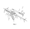
- FIGS. 1 and 2 illustrate one, non-limiting exemplary embodiment of a surgical stapler 10 suitable for use with one or more adjunct materials.
- the instrument 10 includes a handle assembly 12, a shaft 14 extending distally from a distal end 12d of the handle assembly 12, and an attachment portion 16 removably coupled to a distal end 14d of the shaft 14.
- a distal end 16d of the attachment portion 16 includes an end effector 50 having jaws 52, 54, although other types of end effectors can be used with the shaft 14, handle assembly 12, and components associated with the same.
- the surgical stapler includes opposed first and second jaws 52, 54 with the first, lower jaw 52 including an elongate channel 56 ( FIG. 4 ) configured to support a staple cartridge 100, and the second, upper jaw 54 having an inner surface 58 ( FIGS. 3 , 4 , and 6 ) that faces the lower jaw 52 and that is configured to operate as an anvil to help deploy staples of a staple cartridge.
- the jaws 52, 54 are configured to move relative to one another to clamp tissue or other objects disposed therebetween, and an axial drive assembly 80 ( FIG. 11 ) can be configured to pass through at least a portion of the end effector 50 to eject the staples into the clamped tissue.
- a knife blade 81 can be associated with the axial drive assembly 80 to cut tissue during the stapling procedure.
- the handle assembly 12 can have many different configurations designed to manipulate and operate the end effector associated therewith.
- the handle assembly 12 has a pistol-grip type housing 18 with a variety of mechanical components disposed therein to operate various features of the instrument.
- the handle assembly 12 can include mechanical components as part of a firing system actuated by a trigger 20.
- the trigger 20 can be biased to an open position with respect to a stationary handle 22, for instance by a torsion spring, and movement of the trigger 20 toward the stationary handle 22 can actuate the firing system to cause the axial drive assembly 80 to pass through at least a portion of the end effector 50 and eject staples from a staple cartridge disposed therein.
- a torsion spring actuates the firing system to cause the axial drive assembly 80 to pass through at least a portion of the end effector 50 and eject staples from a staple cartridge disposed therein.
- a rotatable knob 24, an articulation lever 26, and retraction knobs 28 are examples of features that can be incorporated into the handle assembly 22 that affect manipulation and operation of an end effector associated therewith.
- the rotatable knob 24 can be mounted on a forward end of a barrel portion 30 of the handle assembly 12 to facilitate rotation of the shaft 14 (or the attachment portion 16) with respect to the handle assembly 12 around a longitudinal axis L of the shaft 14.
- the actuation lever 26 can also be mounted on a forward end of the barrel portion 30, approximately adjacent to the rotatable knob 24.
- the lever 26 can be manipulated from side-to-side along a surface of the barrel portion 30 to facilitate reciprocal articulation of the end effector 50.
- One or more retraction knobs 28 can be movably positioned along the barrel portion 30 to return the drive assembly 80 to a retracted position, for example after the firing system has completed a firing stroke. As shown, the retraction knobs 28 move proximally toward a back end of the barrel portion 30 to retract components of the firing system, including the drive assembly 80.
- a firing lockout assembly can be configured to prevent the firing system from being actuated at an undesirable time, such as when an end effector is not fully coupled to the instrument.
- An anti-reverse clutch mechanism can be configured to prevent components of the firing system from moving backwards when such backwards movement is undesirable, such as when the firing stroke has only been partially completed but temporarily stopped.
- An emergency return button can be configured to permit components of a firing system to be retracted before a firing stroke is completed, for instance in a case where completing the firing stroke may cause tissue to be undesirably cut.
- the shaft 14 can be removably coupled to the distal end 12d of the handle assembly 12 at a proximal end 14p of the shaft 14, and a distal end 14d of the shaft 14 can be configured to receive the attachment portion 16.
- the shaft 14 is generally cylindrical and elongate, although any number of shapes and configurations can be used for the shaft, depending, at least in part, on the configurations of the other instrument components with which it is used and the type of procedure in which the instrument is used.
- a distal end of one shaft can have a particular configuration for receiving certain types of end effectors, while a distal end of another shaft can have a different configuration for receiving certain other types of end effectors.
- Components of the firing system can be disposed in the shaft 14 so that the components can reach the end effector 50 and drive assembly 80 to provide actuation of the same.
- the control rod 32 can be advanced distally through at least a portion of the shaft 14 to cause the jaws 52, 54 to collapse towards each other and/or to drive the drive assembly 80 distally through at least a portion of the end effector 50.
- the shaft 14 can also include one or more sensors (not shown) and related components, such as electronic components to help operate and use the sensors (not shown).
- the sensors and related components can be configured to communicate to a clinician the type of end effector associated with the distal end 14d of the shaft 14, among other parameters.
- the handle assembly 12 can include one or more sensors and related components configured to communicate to a clinician the type of end effector and/or shaft associated with the distal end 12d of the handle assembly 12. Accordingly, because a variety of shafts can be interchangeably coupled with the handle assembly 12 and a variety of end effectors having different configurations can be interchangeably coupled with various shafts, the sensors can help a clinician know which shaft and end effector are being used.
- the information from the sensors can help a monitoring or control system associated with the instrument know which operation and measurement parameters are relevant to a clinician based on the type of shaft and end effector coupled to the handle assembly. For example, when the end effector is a stapler, information about the number of times the drive assembly 80 is fired may be relevant, and when the end effector is another type of end effector, such as a cutting device, the distance the cutting portion traveled may be relevant.
- the system can convey the appropriate information to the clinician based on the end effector that is sensed.
- sensors associated with any of the end effector 50, the attachment portion 16, the shaft 14, and the handle assembly 12 can be configured to monitor other system parameters, and a monitoring or control system can communicate to a clinician the relevant other parameters based on the type of shaft or attachment portion associated with the handle assembly. Further details about sensors and related components, as well as monitoring and control systems, can be found in patents and patent applications incorporated by reference elsewhere in the present application.
- the attachment portion 16 can include a proximal housing portion 34 at a proximal end 16p thereof and an end effector or tool 50 at a distal end 16d thereof.
- the proximal housing portion 34 includes on a proximal end 34p thereof engagement nubs 36 for releasably engaging the shaft 14.
- the nubs 36 form a bayonet type coupling with the distal end 14d of the shaft 14.
- any number of other complementary mating features can be used to allow the attachment portion 16 to be removably coupled to the shaft 14.
- a distal end 34d of the proximal housing portion 34 can include a mounting assembly 40 pivotally secured thereto.
- the mounting assembly 40 can be configured to receive a proximal end 50p of the end effector 50 such that pivotal movement of the mounting assembly 40 about an axis perpendicular to the longitudinal axis of the housing portion 34 effects articulation of the end effector 50 about a pivot member or pin 42.
- This pivotal movement can be controlled by the actuation lever 26 of the handle assembly 28, with components being disposed between the lever 26 and the mounting assembly 40 to allow for movement of the lever 26 to articulate the mounting assembly 40, and thereby the end effector 50.
- the end effector 50 of the illustrated embodiment is a surgical stapling tool having a first, lower jaw 52 that serves as a cartridge assembly or carrier and an opposed second, upper jaw 54 that serves as an anvil.
- an inner surface 58 of the second jaw 54 can include a plurality of staple deforming cavities 60 and a cover plate 62 secured to a top surface 59 of the jaw 54 to define a cavity 64 therebetween.
- the cover plate 62 can help to prevent pinching of tissue during clamping and firing of the surgical stapler.
- the cavity 64 can be dimensioned to receive a distal end 80d of the axial drive assembly 80.
- a longitudinal slot 66 can extend through the anvil portion 58 to facilitate passage of a retention flange 82 of the axial drive assembly 80 into the anvil cavity 64.
- a camming surface 57 formed on the anvil portion 58 can be positioned to engage the axial drive assembly 80 to facilitate clamping of tissue 99.
- a pair of pivot members 53 formed on the anvil portion 54 can be positioned within slots 51 formed in the carrier 52 to guide the anvil portion between the open and clamped positions.
- a pair of stabilizing members can engage a respective shoulder 55 formed on the carrier 52 to prevent the anvil portion 54 from sliding axially relative to the staple cartridge 100 as the camming surface 57 is deformed.
- the carrier 52 and staple cartridge 100 can be pivoted between open and clamped positions while the anvil portion 54 remains substantially stationary.
- the elongated support channel 56 of the first jaw 52 can be dimensioned and configured to receive a staple cartridge 100, as shown in FIGS. 4 , 5, and 7 .
- a pair of support struts 103 formed on the staple cartridge 100 can be positioned to rest on sidewalls of the carrier 52 to further stabilize the staple cartridge 100 within the support channel 56.
- the staple cartridge 100 can also include retention slots 105 for receiving a plurality of fasteners 106 and pushers 108.
- a plurality of spaced apart longitudinal slots 107 can extend through the staple cartridge 100 to accommodate upstanding cam wedges 70 of an actuation sled 72 of a firing system ( FIGS. 4 and 8 ).
- a central longitudinal slot 109 can extend along the length of the staple cartridge 100 to facilitate passage of a knife blade 81 associated with the axial drive assembly 80.
- the actuation sled 72 translates through longitudinal slots 107 of the staple cartridge 100 to advance cam wedges 70 into sequential contact with pushers 108, thereby causing the pushers 108 to translate vertically within the retention slots 105 and urge the fasteners 106 from the slots 105 into the staple deforming cavities 60 of the anvil portion 54.
- the attachment portion 16' can include a proximal housing portion 34' at a proximal end 16p' thereof and an end effector or tool 50' at a distal end 16d' thereof.
- Nubs 36' can be provided to removably couple the attachment portion 16' to a shaft of a surgical instrument, and a mounting assembly 40' can be provided to removably and/or pivotally couple an end effector or tool 50' to the proximal housing portion 34'.
- the end effector 50' can include a first, lower jaw 52' that serves as a cartridge assembly, and a second, upper jaw 54' that serves as an anvil portion.
- the first jaw 52' can have many of the same features as the first jaw 52 of FIGS. 3 , 4 , and 6 , and thus can include an elongated support channel 56' that is dimensioned and configured to receive a staple cartridge 100', and slots 68' configured to correspond with tabs 102' of the staple cartridge 100' to retain the cartridge 100' within the channel 56'.
- the cartridge 100' can include support struts 103' to rest on sidewalls of the jaw 52', retention slots 105' for receiving a plurality of fasteners 106' and pushers 108', a plurality of spaced apart longitudinal slots 107' to accommodate upstanding cam wedges 70' of an actuation sled 72' of a firing system, and a central longitudinal slot 109' to facilitate passage of a knife blade 81' associated with an axial drive assembly 80'.
- the second jaw 54' can include a cover plate 62' secured to a top surface of the jaws to define a cavity therebetween.
- An anvil plate 58' can serve as the inner surface of the jaw 54', and can include a longitudinal slot 66' for receiving a distal end of the axial drive assembly 80', and a plurality of staple deforming pockets or cavities (not shown) to form staples ejected from the cartridge 100'.
- the lower jaw 52' containing the cartridge 100' is configured to pivot toward the upper jaw 54' while the upper jaw 54' remains substantially stationary upon actuation by a handle assembly and related components.
- the end effector and staple cartridge disposed therein is configured to receive an axial drive assembly.
- One non-limiting exemplary embodiment of the axial drive assembly 80 is illustrated in FIG. 11 .
- a distal end of a drive beam 84 can be defined by a vertical support strut 86 that supports the knife blade 81, and an abutment surface 88 configured to engage the central portion of the actuation sled 72 during a stapling procedure.
- Bottom surface 85 at the base of the abutment surface 88 can be configured to receive a support member 87 slidably positioned along the bottom of the staple cartridge 100 ( FIGS. 4 and 6 ).
- the knife blade 81 can be positioned to translate slightly behind the actuation sled 72 through the central longitudinal slot 109 in the staple cartridge 100 to form an incision between rows of stapled body tissue.
- the retention flange 82 can project distally from the vertical strut 86 and can support a cylindrical cam roller 89 at its distal end.
- the cam roller 89 can be dimensioned and configured to engage the camming surface 57 on the anvil portion 58 to clamp the anvil portion 58 against body tissue.
- the drive assembly 80 can include a single drive beam, or any other number of drive beams, and the distal end of the drive beam(s) can have any number of shapes that are configured for use in the end effector through which the drive assembly is configured to travel.
- the surgical stapler can be disposed in a cannula or port and disposed at a surgical site.
- a tissue to be cut and stapled can be placed between the jaws 52, 54 of the surgical stapler 10.
- Features of the stapler 10, such as the rotating knob 24 and the actuation lever 26, can be maneuvered as desired by the clinician to achieve a desired location of the jaws 52, 54 at the surgical site and the tissue with respect to the jaws 52, 54.
- the trigger 20 can be pulled toward the stationary handle 22 to actuate the firing system.
- the trigger 20 can cause components of the firing system to operate such that the control rod 32 advances distally through at least a portion of the shaft 14 to cause at least one of the jaws 52, 54 to collapse towards the other to clamp the tissue disposed therebetween and/or to drive the drive assembly 80 distally through at least a portion of the end effector 50.
- a first firing of the trigger 20 can cause the jaws 52, 54 to clamp the tissue, while subsequent firings of the trigger 20 can cause the drive assembly 80 to be advanced distally through at least a portion of the end effector 50.
- a single, subsequent firing can fully advance the drive assembly 80 through the staple cartridge 100 to eject the staples in the row, or alternatively, the components in the handle assembly 12 can be configured such that multiple, subsequent firings are required to fully advance the drive assembly 80 through the staple cartridge 100 to eject the staples in the row. Any number of subsequent firings can be required, but in some exemplary embodiments anywhere from two to five firings can fully advance the drive assembly 80 through the staple cartridge 100.
- the knife 81 cuts tissue as the drive assembly advances distally through the end effector 50, and thus the staple cartridge 100 disposed therein.
- a motor disposed within the handle assembly 12 and associated with a firing trigger can actuate the drive assembly 80 automatically in response to activation of the firing trigger.
- the retraction knobs 28 can be advanced proximally to retract the drive assembly 80 back towards its initial position. In some configurations, the retraction knobs 28 can be used to retract the drive assembly 80 prior to fully advancing the assembly 80 through the cartridge 100. In other embodiments retraction of the drive assembly 80 can be automated to occur after a predetermined action. For example, once the drive assembly 80 has distally advanced to its desired location, the subsequent return of the trigger 80 back to a biased open position can cause the drive assembly 80 to automatically retract. A motor and associated components, rather than retraction knobs 28 and associated components, can be used to retract the drive assembly 80. Further, as discussed above, other features, such as a firing lockout mechanism, an anti-reverse clutch mechanism, and an emergency return button, can be relied upon during operation of the surgical stapler 10, as would be understood by those skilled in the art.
- the illustrated embodiment of a surgical stapling instrument 10 provides one of many different configurations, and associated methods of use, that can be used in conjunction with the disclosures provided herein. Additional exemplary embodiments of surgical staplers, components thereof, and their related methods of use, that can be used in accordance with the present disclosure include those devices, components, and methods provided for in U.S. Patent Application Publication No. 2012/0083835 and U.S. Patent Application Publication No. 2013/0161374 , each of which is incorporated by reference herein in its entirety.
- the present disclosure provides for the use of implantable materials, e.g ., biologic materials and/or synthetic materials, collectively "adjunct materials," in conjunction with instrument operations.
- implantable materials e.g ., biologic materials and/or synthetic materials, collectively "adjunct materials," in conjunction with instrument operations.
- the end effector 50 can include at least one piece of adjunct material 200, 200' positioned intermediate the first and second jaw members 52, 54 and it can be releasably retained to one of the support channel 56 and/or the anvil portion 58.
- the releasable retention is provided by retention members 202, 202', which are described in further detail below.
- a surface on the adjunct material 200, 200' can be configured to contact tissue as the tissue is clamped between the first and second jaw members 52, 54.
- the adjunct material can be used to distribute the compressive clamping force over the tissue, remove excess fluid from the tissue, and/or improve the purchase of the staples.
- one or more pieces of adjunct material can be positioned within the end effector 50.
- one piece of adjunct material 200 can be attached to the staple cartridge 100 ( FIG. 12 ) and one piece of adjunct material 200' can be attached to the anvil portion 58 ( FIG. 13 ).
- two pieces of adjunct material 200 can be positioned on the support channel 56 and one piece of adjunct material 200' can be positioned on the anvil portion 58, for example. Any suitable number of adjunct materials can be situated within the end effector 50.
- Adjunct material used in conjunction with the disclosures provided for herein can have any number of configurations and properties. Generally, they can be formed from of a bioabsorbable material, a biofragmentable material, and/or a material otherwise capable of being broken down, for example, such that the adjunct material can be absorbed, fragmented, and/or broken down during the healing process.
- the adjunct material can include a therapeutic drug that can be configured to be released over time to aid the tissue in healing, for example.
- the adjunct materials can include a non-absorbable and/or a material not capable of being broken down, for example.
- connection members can be at least partially formed from at least one of a bioabsorbable material, a biofragmentable material, and a material capable of being broken down such that the connection members can be absorbed, fragmented, and/or broken down within the body.
- the connection members can include a therapeutic drug that can be configured to be released over time to aid the tissue in healing, for example.
- the connection members can include a non-absorbable and/or a material not capable of being broken down, for example, such as a plastic.
- biodegradable synthetic absorbable polymer such as a polydioxanon film sold under the trademark PDS ® or with a Polyglycerol sebacate (PGS) film or other biodegradable films formed from PGA (Polyglycolic acid, marketed under the trade mark Vicryl), PCL (Polycaprolactone), PLA or PLLA (Polylactic acid), PHA (polyhydroxyalkanoate), PGCL (poliglecaprone 25, sold under the trademark Monocryl), PANACRYL (Ethicon, Inc., Somerville, N.J.), Polyglactin910, Poly glyconate, PGA/TMC (polyglycolide-trimethylene carbonate sold under the trademark Biosyn), polyhydroxybutyrate (PHB), poly(vinylpyrrolidone) (PVP), poly(vinyl alcohol) (PVA), or a blend of
- the synthetic material can be broken down by exposure to water such that the water attacks the linkage of a polymer of the synthetic material.
- the mechanical strength can become diminished, and a construct of the material can be broken down into a mushy or fractured scaffold.
- a patient's body can metabolize and expel the broken down materials.
- biologic derived materials that can be used in conjunction with the disclosures provided for herein include platelet poor plasma (PPP), platelet rich plasma (PRP), starch, chitosan, alginate, fibrin, thrombin, polysaccharide, cellulose, collagen, bovine collagen, bovine pericardium, gelatin-resorcin-formalin adhesive, oxidized cellulose, mussel-based adhesive, poly (amino acid), agarose, polyetheretherketones, amylose, hyaluronan, hyaluronic acid, whey protein, cellulose gum, starch, gelatin, silk, or other material suitable to be mixed with biological material and introduced to a wound or defect site, including combinations of materials, or any material apparent to those skilled in the art in view of the disclosures provided for herein.
- Biologic materials can be derived from a number of sources, including from the patient in which the biologic material is to be implanted, a person that is not the patient in which
- the adjunct material can come pre-loaded onto the device and/or the staple cartridge, while in other instances the adjunct material can be packaged separately.
- the stapling procedure can be carried out as known to those skilled in the art.
- the firing of the device can be enough to disassociate the adjunct material from the device and/or the staple cartridge, thereby requiring no further action by the clinician.
- any remaining connection or retention member associating the adjunct material with the device and/or the staple cartridge can be removed prior to removing the instrument from the surgical site, thereby leaving the adjunct material at the surgical site.
- the material can be releasably coupled to at least one of a component of the end effector and the staple cartridge prior to firing the device.
- the adjunct material may be refrigerated, and thus removed from the refrigerator and the related packaging, and then coupled to the device using a connection or retention member as described herein or otherwise known to those skilled in the art.
- the stapling procedure can then be carried out as known to those skilled in the art, and if necessary, the adjunct material can be disassociated with the device as described above.
- Connection or retention members can be used to secure, at least temporarily, one or more pieces of adjunct material onto an end effector and/or staple cartridge.
- These retention members can come in a variety of forms and configurations, such as one or more sutures, adhesive materials, staples, brackets, snap-on or other coupling or mating elements, etc.
- the retention members can be positioned proximate to one or more sides and/or ends of the adjunct material, which can help prevent the adjunct material from peeling away from the staple cartridge and/or the anvil face when the end effector is inserted through a trocar or engaged with tissue.
- the retention members can be used with or in the form of an adhesive suitable to releasably retain the adjunct material to the end effector, such as cyanoacrylate.
- the adhesive can be applied to the retention members prior to the retention members being engaged with the adjunct material, staple cartridge, and/or anvil portion.
- the retention member(s) can be detached from the adjunct material and/or the end effector so that the adjunct material can stay at the surgical site when the end effector is removed.
- FIG. 12 illustrates one exemplary embodiment of a connection or retention member 202 associated with the adjunct material 200 to secure the material 200 at a temporary location with respect to the lower jaw 52 of the end effector 50.
- the adjunct material 200 is disposed over the staple cartridge 100 located in the elongate channel 56 of the lower jaw 52, and the retention member 202 extends therethrough.
- the retention member 202 is in the form of a single suture stitched through multiple locations of the adjunct material 200, or it can be multiple sutures disposed at one or more locations on the adjunct material 200.
- the sutures are positioned at locations around a perimeter of the adjunct material 200, and are also adjacent to a central longitudinal channel 201 formed in the adjunct material 200.
- the channel 201 can make it easier for a knife passing through the adjunct material 200 to cut the material 200 into two or more separate strips.
- a knife passing through the lower jaw 52 can cut the retention member 202 at one or more locations, thereby allowing the retention member 202 to be disassociated from the adjunct material 200 and removed from the surgical site while the adjunct material 200 remains held at the surgical site by one or more staples ejected from the cartridge 100.
- FIG. 13 illustrates another embodiment of a connection or retention member 202' associated with the adjunct material 200' to secure the material 200' at a temporary location on the end effector 50.
- the retention member 202' has the same configuration as the retention member 202 in FIG. 12 , however, in this embodiment it is used to secure the material to the anvil or upper jaw 54, rather than the cartridge or lower jaw 52.
- FIG. 14 illustrates another, non-limiting embodiment of a connection or retention member 202" used to releasably retain an adjunct material 200" to at least one of the upper jaw 54 and the lower jaw 52.
- the retention member 202" is a single suture that extends through a distal portion 200d" of the adjunct material 200" and is coupled to a proximal end 54p of the upper jaw 54. Terminal ends 202t" of the retention member 202" can be used to move the retention member 202" with respect to the jaws 54, 52. In its extended position, which is illustrated in FIG. 14 , the retention member 202" can hold the adjunct material 200" in position as the end effector 50 is inserted into a surgical site.
- the jaws 52, 54 of the end effector 50 can be closed onto tissue, for example, and staples from the staple cartridge 100 can be deployed through the adjunct material 200" and into the tissue.
- the retention member 202" can be moved into its retracted position such that the retention member 202" can be operably disengaged from the adjunct material 200".
- the retention member 202" can be retracted prior to the staples being deployed.
- the end effector 50 can be opened and withdrawn from the surgical site leaving behind the adjunct material 200" and tissue.
- FIG. 15 illustrates yet another, non-limiting embodiment of a connection or retention member 202'" for securing a location of adjunct material 200'" to an end effector.
- the adjunct material 200'" and retention member 202'" are used in conjunction with the end effector 50' of FIGS. 9 and 10 .
- the retention member 202'" is in the form of a suture that is used to tie the adjunct material 200'" to the first, lower jaw 52' at proximal and distal ends thereof 52p', 52d'.
- the adjunct material 200'" can also be secured to the second, upper jaw 54' at proximal and distal ends thereof 54p', 54d'.
- recesses can be formed in either or both of the jaws 52', 54', and either or both of the adjunct materials 200"', which can protect the retention members 202'" against unintended cutting by an outside object.
- the knife blade 81' on the driver assembly 80' can incise the retention members 202'" as it passes through the end effector 50' to release the adjunct material 200"'.
- a connection or retention member can be configured to be released from an end effector and deployed along with a piece of adjunct material.
- head portions of retention members can be configured to be separated from body portions of retention members such that the head portions can be deployed with the adjunct material while the body portions remain attached to the end effector.
- the entirety of the retention members can remain engaged with the end effector when the adjunct material is detached from the end effector.
- adjunct materials are provided for use with a surgical stapler. While in some instances the adjunct materials can be a synthetic material and/or a biologic material, in some exemplary embodiments the adjunct material can be especially configured to facilitate tissue ingrowth into the materials. While this can be achieved using various techniques, in one embodiment the adjunct material can include both hydrophilic portions and hydrophobic portions to form a hydrophilic-hydrophobic adjunct material. The resulting combination can advantageously have surfaces or portions that attract cells and encourage cell ingrowth (hydrophilic) and surfaces or portions that do not attract cells or otherwise encourage cell ingrowth (hydrophobic). In use, the hydrophobic portions can be placed in contact with the tissue, while the hydrophobic portions can be oriented away from the tissue surface.
- synthetic polymers used to form adjunct materials can be hydrophobic, such as polycaprolactone (PCL) and polylactic acid (PLLA). It is noted that "polymers” as used herein can include copolymers. Synthetic adjunct materials, however, can be treated or otherwise produced to be hydrophilic, as will be discussed herein. To form the adjunct material, any method of creating a synthetic material having a hydrophilic portion and a hydrophobic portion can be used. In some embodiments, a surface of (or only half of) a hydrophobic adjunct material is treated with an acid or base which can cause the formation of pockets or pits in the surface. Alternatively, the adjunct material can be formed by bonding a hydrophilic layer to a hydrophobic layer.
- an adjunct material can be treated such that the entire adjunct material becomes hydrophilic. Then this hydrophilic layer can be bound, such as by laminating, to a second hydrophobic adjunct material layer creating a material that is hydrophobic and hydrophilic.
- Various approaches can be used to create an adjunct material or matrix where a tissue contacting portion encourages cellular ingrowth while a non-tissue contacting portion discourages cellular ingrowth.
- adjunct material can be made hydrophilic and/or hydrophobic.
- any form of adjunct material can be made to be hydrophilic and/or hydrophobic, for example a film type adjunct material and/or a foam type adjunct material.
- a film or foam can be made hydrophilic using any suitable technique, such as surface grafting techniques and coating techniques, depending upon the physical or chemical characteristics of the film or foam.
- the film or foam can be made hydrophilic by covalently binding hydrophilic moieties or surfactants onto the film or foam.
- hydrophilic moieties can include, but are not limited to, polyethylene glycol (PEG) and poloxamers (available under the trade names Pluronic® available from BASF, Synperonic® available from Sigma Aldrich, and Kolliphor available from BASF).
- Coating techniques can be used, for example, if the film or foam does not have any reactive sites as it will generally not be possible to impart the hydrophilic characteristics using surface grating techniques.
- Various levels of coating with a hydrophilic polymer will impart varying degrees of hydrophilicity to the foam or film.
- hydrophilic 65:35 PGA/PCL polymers can be prepared by copolymerizing PEG/Pluronic with PCL/PGA. Introduction of PEG or poloxamer repeat units in the copolymer backbone can render the backbone hydrophilic resulting in swelling upon contact with body fluids including blood.
- the hydrophilicity of the polymer can be controlled by using various molecular weights of PEG and poloxamers and the ratio of PEG/poloxamer to PCL/PGA. For example, higher content of PEG/poloxamer is expected to result in higher swelling and higher hydrophilicity.
- An adjunct material can be selectively attached to either or both jaws of an end effector.
- an adjunct material 400, 400' can be attached to both lower and upper jaws 1052, 1054 of an end effector 1050.
- the adjunct material 400, 400' can have a first side 402, 402' that is hydrophobic and a second side 404, 404' that is hydrophilic.
- the first, hydrophobic side 402, 402' can be configured to face and directly contact the upper and lower jaws 1052, 1054, while the second, hydrophilic side 404, 404' can be oriented away from the upper and/or lower jaws 1052, 1054.
- the second hydrophilic side 404, 404' will face and directly contact the tissue being treated ( i.e., grasped by the end effector 1050) once the end effector 1052 is actuated, and the first, hydrophobic side 402, 402' will be on an opposite side facing away from the tissue being treated or grasped.
- This configuration is illustrated in FIGS. 18A and 18B , as will be discussed in detail below.
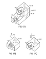
- FIGS. 17A-17C illustrate the adjunct material 400, 400' when wetted by a drop of water 406.
- the hydrophilic side 404, 404' absorbs the water 406 and disperses the water 406 through the layer 404, 404'.
- the hydrophobic side 402, 402' repels the water 406, which remains substantially on the surface of the hydrophobic layer 402, 402'.
- the adjunct material 400 can be positioned in a body, such as is shown in FIGS. 18A and 18B .
- the adjunct material 400 is implanted at a treatment site using staples 408 such that the hydrophilic side 404 of the adjunct material 400 is directly contacting the tissue to be treated 410 and the hydrophobic side 402 on an opposite side and is exposed to an adjacent tissue 412, such as an organ where tissue ingrowth is not desired.
- the hydrophilic side 404 enhances cellular ingrowth into the grasped tissue 410 and the hydrophobic side 402 discourages cellular ingrowth and therefore prevents the hydrophobic side from attaching to adjacent tissue 412.
- FIG. 18B illustrates this further as the hydrophilic side 404 is in contact with the tissue to be treated 410, but not the adjacent tissue 412 and the hydrophobic side is in contact with the adjacent tissue 412, but not the tissue to be treated 410.
- typically synthetic absorbable materials are hydrophobic and at best do not inhibit healing and at worst are treated like foreign bodies during healing. It is possible, however, to take a hydrophobic matrix, like PGA/PCL, and micro-etch or pit the surface of the polymer to make the material more hydrophilic. Once etched or pitted, it is further possible to deposit or coat the synthetic absorbable material with a biologic material, such as collagen or fibrin, so as to form an synthetic absorbable material that has a biologic coating, which enhances healing as a biologic but retains the structural properties of the synthetic absorbable material.
- a biologic material such as collagen or fibrin
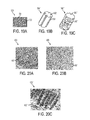
- FIGS. 19A-19C illustrate various synthetic absorbable materials having surface features and characteristics, such as nanofeatures, that create a macro-structure that has the effect of creating a hydrophilic surface thus allowing for biologic coating.
- FIG. 19A depicts an adjunct material that is woven 500.
- the woven material creates surface features 502, i.e., pockets, that can entrap a biologic.
- the woven adjunct material 500 can be formed of fibers 504 that are either hydrophilic or hydrophobic, or combinations thereof, which allow the woven material to be an hydrophilic-hydrophobic material, as well as enables it to have a biologic coating.
- FIG. 19B depicts a synthetic absorbable material 500' that has micro-etched surface features 502' that are produced using a laser etching technique.
- FIG. 19C illustrates a synthetic absorbable material 500" that has been treated with a surface hydrolysis technique.
- This surface hydrolysis can be done through introduction of a strong acid or base that is then washed off or freeze dried away before it destroys the entire matrix. This surface hydrolysis results in surface pitting forming a macro-structure that creates a hydrophilic surface and thus encourages cellular ingrowth.
- weaving, laser etching, surface coating, plasma treatment, surface grafting, and/or blending can be done to improve the hydrophilic properties of the synthetic absorbable material.
- These surface etching and pitting techniques can not only make the adjunct material (or scaffold) hydrophilic, it can leave pitted surfaces that retain fluids once they are encourage to move into the structure.
- FIGS. 20A-20C are scanning electron microscope images of synthetic absorbable materials 600, 600', 600" having surface pitting 602, 602', 602".
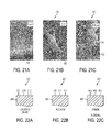
- FIGS. 21A-21C are scanning electron microscope images of synthetic absorbable materials 700, 700', 700" having micro-etched nanofeatures 702, 702', 702" on their surface. As shown in FIGS. 21B and 21C , cells 704 adhere or attach to the nanofeatures 702', 702" and thus encourage cellular ingrowth.
- FIGS. 22A-22C illustrate additional surface features, i.e., function groups, 802, 802', 802" that can be formed on synthetic absorbable material 800, 800', 800" using plasma etching and/or polymer etching techniques.
- FIG. 22A shows the result of plasma etching and/or polymer grafting that occurs when oxidation in air occurs
- FIG. 22B shows that hydroxyl groups 802' are formed when an aldehyde is used
- FIG. 22C shows that amine groups 802" are formed when diamines and blending are used.
- Coating the micro-etched or pitted synthetic absorbable material can be achieved by any suitable method. For example, once the pitted or etched surface is formed, it can be saturated with a liquified collagen, fibrin, or other biologic material. Following saturation, the saturated synthetic absorbable adjunct material or scaffold can then be freeze dried or lyophilized to create a biologic surface coating that will be retained in the pits even after hydrating the adjunct material or scaffold. This biologically coated synthetic material can act like a biologic to in growing cells while still retaining desired synthetic properties, as discussed above.
- the devices disclosed herein can be designed to be disposed of after a single use, or they can be designed to be used multiple times. In either case, however, the device can be reconditioned for reuse after at least one use. Reconditioning can include any combination of the steps of disassembly of the device, followed by cleaning or replacement of particular pieces, and subsequent reassembly. In particular, the device can be disassembled, and any number of the particular pieces or parts of the device can be selectively replaced or removed in any combination, e.g., electrodes, a battery or other power source, an externally wearable sensor and/or housing therefor, etc.
- the device can be reassembled for subsequent use either at a reconditioning facility, or by a surgical team immediately prior to a surgical procedure.
- reconditioning of a device can utilize a variety of techniques for disassembly, cleaning/replacement, and reassembly. Use of such techniques, and the resulting reconditioned device, are all within the scope of the present application.
- devices described herein can be processed before surgery.
- a new or used instrument is obtained and if necessary cleaned.
- the instrument can then be sterilized.
- the instrument is placed in a closed and sealed container, such as a plastic or TYVEK bag.
- the container and instrument are then placed in a field of radiation that can penetrate the container, such as gamma radiation, x-rays, or high-energy electrons.
- the radiation kills bacteria on the instrument and in the container.
- the sterilized instrument can then be stored in the sterile container.
- the sealed container keeps the instrument sterile until it is opened in the medical facility.
Landscapes
- Health & Medical Sciences (AREA)
- Life Sciences & Earth Sciences (AREA)
- Surgery (AREA)
- Molecular Biology (AREA)
- Engineering & Computer Science (AREA)
- Biomedical Technology (AREA)
- Heart & Thoracic Surgery (AREA)
- Medical Informatics (AREA)
- Nuclear Medicine, Radiotherapy & Molecular Imaging (AREA)
- Animal Behavior & Ethology (AREA)
- General Health & Medical Sciences (AREA)
- Public Health (AREA)
- Veterinary Medicine (AREA)
- Surgical Instruments (AREA)
- Laminated Bodies (AREA)
- Materials For Medical Uses (AREA)
Abstract
Description
- The present invention relates to surgical instruments, and in particular to methods, devices, and components thereof for cutting and stapling tissue.
- Surgical staplers are used in surgical procedures to close openings in tissue, blood vessels, ducts, shunts, or other objects or body parts involved in the particular procedure. The openings can be naturally occurring, such as passageways in blood vessels or an internal organ like the stomach, or they can be formed by the surgeon during a surgical procedure, such as by puncturing tissue or blood vessels to form a bypass or an anastomosis, or by cutting tissue during a stapling procedure.
- Most staplers have a handle with an elongate shaft having a pair of movable opposed jaws formed on an end thereof for holding and forming staples therebetween. The staples are typically contained in a staple cartridge, which can house multiple rows of staples and is often disposed in one of the two jaws for ejection of the staples to the surgical site. In use, the jaws are positioned so that the object to be stapled is disposed between the jaws, and staples are ejected and formed when the jaws are closed and the device is actuated. Some staplers include a knife configured to travel between rows of staples in the staple cartridge to longitudinally cut and/or open the stapled tissue between the stapled rows.
- While surgical staplers have improved over the years, a number of problems still present themselves. One common problem is that leaks can occur due to the staple forming holes when penetrating the tissue or other object in which it is disposed. Blood, air, gastrointestinal fluids, and other fluids can seep through the openings formed by the staples, even after the staple is fully formed. The tissue being treated can also become inflamed due to the trauma that results from stapling. Still further, staples, as well as other objects and materials that can be implanted in conjunction with procedures like stapling, generally lack some characteristics of the tissue in which they are implanted. For example, staples and other objects and materials can lack the natural flexibility of the tissue in which they are implanted. A person skilled in the art will recognize that it is often desirable for tissue to maintain as much of its natural characteristics as possible after staples are disposed therein.
- Accordingly, there remains a need for improved devices and methods for stapling tissue, blood vessels, ducts, shunts, or other objects or body parts such that leaking and inflammation is minimized while substantially maintaining the natural characteristics of the treatment region.
- Implantable materials for use with end effectors like surgical stapling devices, and methods for using the same, are generally provided. In some embodiments, adjunct materials for use with surgical staplers are provided. For example, a kit for stapling tissue is provided that can include a surgical stapler having an end effector. The end effector can have first and second jaws. The kit can include an adjunct material having hydrophobic surface regions and hydrophilic surface regions and the adjunct material can be configured to mate to at least one of the jaws of the end effector.
- In some embodiments, the adjunct material can be formed from a hydrophobic polymer and/or coploymer that is treated with a hydrophilic polymer. The adjunct material can also be formed from a hydrophobic polymer and/or coploymer that is treated with an acid or base. In some embodiments, the adjunct material can be formed from a hydrophobic polymer that is treated by covalently bonding hydrophilic moieties onto at least a portion of the hydrophobic polymer. The hydrophilic surface region can be laminated to the hydrophobic surface region. The adjunct material can include an absorbable polymer. In some embodiments, the adjunct material can include a copolymer selected from the group consisting of polyglycolic acid/polycaprolactone and polylactic acid/polycaprolactone. Also, the adjunct material can include a foam.
- In some exemplary embodiments a staple cartridge assembly for use with a surgical stapler, can include a cartridge body having a plurality of staples disposed therein and an adjunct material configured to be coupled to the cartridge and configured to be securely attached to tissue by staples in the cartridge. The adjunct material can have a hydrophobic surface region and an opposite hydrophilic surface region. In some embodiments, the adjunct material can be formed from a hydrophobic polymer and/or coploymer that is treated with a hydrophilic polymer. The adjunct material can also be formed from a hydrophobic polymer and/or coploymer that is treated with an acid or base. In some embodiments, the adjunct material can be formed from a hydrophobic polymer that is treated by covalently bonding hydrophilic moieties onto at least a portion of the hydrophobic polymer. In some embodiments, the hydrophilic surface region can be configured to directly contact tissue when secured to tissue by the staples such that tissue ingrowth is encouraged. The adjunct material can include a copolymer selected from the group consisting of polyglycolic acid/polycaprolactone and polylactic acid/polycaprolactone. In some embodiments, the adjunct material include a polyglycolic acid/polycaprolactone copolymer having polyethylene glycol and/or poloxamer repeat units. The adjunct material can include at least one of a biologic material, an electrically charged material, and an internal support structure. Also, the adjunct material can include a foam.
- In other aspects, a method for stapling tissue is provided. The method can include attaching an adjunct material to an end effector on a surgical stapling device such that a hydrophobic surface on the adjunct material directly contacts the end effector. The method can also include engaging tissue between the jaws of the end effector such that a hydrophilic surface on the adjunct material directly contacts the tissue, and actuating the end effector to eject at least one staple from the end effector into the tissue. The at least one staple can extend through the adjunct material to attach the adjunct material to the tissue. In some embodiments, the adjunct material can include a polyglycolic acid/polycaprolactone copolymer having polyethylene glycol and/or poloxamer repeat units. Also, the hydrophilic surface can include a first layer of material and the hydrophobic surface can be a coating that is laminated to the first layer of material.
- The invention will be more fully understood from the following detailed description taken in conjunction with the accompanying drawings, in which:
-
FIG. 1 is a perspective view of one exemplary embodiment of a surgical instrument having an attachment portion attached to a distal end thereof; -
FIG. 2 is a perspective view of the surgical instrument ofFIG. 1 with the attachment portion detached from a shaft of the instrument; -
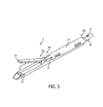
FIG. 3 is a perspective view of the attachment portion ofFIG. 2 including at least one piece of adjunct material; -
FIG. 4 is an exploded perspective view of the end effector ofFIG. 3 with the adjunct material removed; -
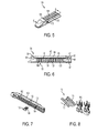
FIG. 5 is a detailed perspective view of a distal end of a staple cartridge for use with the end effector ofFIG. 4 ; -
FIG. 6 is a side cross-sectional view taken along the section line indicated inFIG. 5 ; -
FIG. 7 is a bottom perspective view of the staple cartridge ofFIG. 5 ; -
FIG. 8 is a detailed perspective view of an actuation sled, pushers, and fasteners of the surgical instrument ofFIG. 4 ; -
FIG. 9 is a perspective view of another exemplary embodiment of an attachment portion for use a surgical instrument; -
FIG. 10 is an exploded perspective view of an end effector of the attachment portion ofFIG. 9 ; -
FIG. 11 is an exploded view of a drive assembly for use with the end effector ofFIG. 4 ; -
FIG. 12 is a perspective view of a lower jaw of the end effector ofFIG. 3 ; -
FIG. 13 is a perspective view of an upper jaw of the end effector ofFIG. 3 , the upper jaw having an adjunct material associated therewith; -
FIG. 14 is a perspective view of portions of the end effector ofFIG. 2 including a retention member configured to releasably retain an adjunct material; -
FIG. 15 is a perspective view of a lower jaw of the end effector ofFIG. 10 ; -
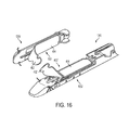
FIG. 16 is a perspective view of portions of an end effector having an adjunct material associated therewith; -
FIG. 17A is a partial cutaway view of an exemplary adjunct material having a drop of water disposed thereon; -
FIG. 17B is a partial cutaway view of an exemplary hydrophobic adjunct material having a drop of water disposed thereon; -
FIG. 17C is a cross-sectional view of an exemplary hydrophilic adjunct material having a drop of water disposed thereon; -
FIG. 18A is a side view of an adjunct material maintained adjacent a tissue to be treated and an adjacent organ by staples; -
FIG. 18B is a cross-sectional view of an exemplary adjunct material disposed between a tissue to be treated and an adjacent organ; -
FIGS. 19A-19B are perspective views of exemplary adjunct materials having surface features; -
FIGS. 20A-20C are scanning electron microscope images of exemplary adjunct materials having surface features; -
FIGS. 21A-21C are scanning electron microscope images of exemplary adjunct materials having surface features; and -
FIGS. 22A-22C are perspective views of exemplary adjunct materials having surface features. - Certain exemplary embodiments will now be described to provide an overall understanding of the principles of the structure, function, manufacture, and use of the devices and methods disclosed herein. One or more examples of these embodiments are illustrated in the accompanying drawings. Those skilled in the art will understand that the devices and methods specifically described herein and illustrated in the accompanying drawings are non-limiting exemplary embodiments and that the scope of the present invention is defined solely by the claims. The features illustrated or described in connection with one exemplary embodiment may be combined with the features of other embodiments. Such modifications and variations are intended to be included within the scope of the present invention.
- Reference throughout the specification to "various embodiments," "some embodiments," "one embodiment," or "an embodiment," or the like, means that a particular feature, structure, or characteristic described in connection with the embodiment is included in at least one embodiment. Thus, appearances of the phrases "in various embodiments," "in some embodiments," "in one embodiment," or "in an embodiment," or the like, in places throughout the specification are not necessarily all referring to the same embodiment. Furthermore, the particular features, structures, or characteristics may be combined in any suitable manner in one or more embodiments. Thus, the particular features, structures, or characteristics illustrated or described in connection with one embodiment may be combined, in whole or in part, with the features structures, or characteristics of one or more other embodiments without limitation. Such modifications and variations are intended to be included within the scope of the present invention.
- The terms "proximal" and "distal" are used herein with reference to a clinician manipulating the handle portion of the surgical instrument. The term "proximal" referring to the portion closest to the clinician and the term "distal" referring to the portion located away from the clinician. It will be further appreciated that, for convenience and clarity, spatial terms such as "vertical," "horizontal," "up," and "down" may be used herein with respect to the drawings. However, surgical instruments are used in many orientations and positions, and these terms are not intended to be limiting and/or absolute.
- Various exemplary devices and methods are provided for performing laparoscopic and minimally invasive surgical procedures. However, a person skilled in the art will appreciate that the various methods and devices disclosed herein can be used in numerous surgical procedures and applications. Those skilled in the art will further appreciate that the various instruments disclosed herein can be inserted into a body in any way, such as through a natural orifice, through an incision or puncture hole formed in tissue, or through an access device, such as a trocar cannula. For example, the working portions or end effector portions of the instruments can be inserted directly into a patient's body or can be inserted through an access device that has a working channel through which the end effector and elongated shaft of a surgical instrument can be advanced.
- It can be desirable to use one or more biologic materials and/or synthetic materials, collectively referred to herein as "adjunct materials," in conjunction with surgical instruments to help improve surgical procedures. A person skilled in the art may refer to these types of materials as adjunct materials. While a variety of different end effectors can benefit from the use of adjunct materials, in some exemplary embodiments the end effector can be a surgical stapler. When used in conjunction with a surgical stapler, the adjunct material(s) can be disposed between and/or on jaws of the stapler, incorporated into a staple cartridge disposed in the jaws, or otherwise placed in proximity to the staples. When staples are deployed, the adjunct material(s) can remain at the treatment site with the staples, in turn providing a number of benefits. In some instances, the material(s) can be used to help seal holes formed by staples as they are implanted into tissue, blood vessels, and various other objects or body parts. Further, the materials can be used to provide tissue reinforcement at the treatment site. Still further, the materials can help reduce inflammation, promote cell growth, and otherwise improve healing.
- While a variety of surgical instruments can be used in conjunction with the adjunct materials disclosed herein,
FIGS. 1 and2 illustrate one, non-limiting exemplary embodiment of asurgical stapler 10 suitable for use with one or more adjunct materials. As shown theinstrument 10 includes ahandle assembly 12, ashaft 14 extending distally from adistal end 12d of thehandle assembly 12, and anattachment portion 16 removably coupled to adistal end 14d of theshaft 14. Because the illustrated embodiment is a surgical stapler, adistal end 16d of theattachment portion 16 includes anend effector 50 havingjaws shaft 14, handleassembly 12, and components associated with the same. As shown, the surgical stapler includes opposed first andsecond jaws lower jaw 52 including an elongate channel 56 (FIG. 4 ) configured to support astaple cartridge 100, and the second,upper jaw 54 having an inner surface 58 (FIGS. 3 ,4 , and6 ) that faces thelower jaw 52 and that is configured to operate as an anvil to help deploy staples of a staple cartridge. Thejaws FIG. 11 ) can be configured to pass through at least a portion of theend effector 50 to eject the staples into the clamped tissue. In various embodiments aknife blade 81 can be associated with theaxial drive assembly 80 to cut tissue during the stapling procedure. - Operation of the
end effector 50 and driveassembly 80 can begin with input from a clinician at thehandle assembly 12. Thehandle assembly 12 can have many different configurations designed to manipulate and operate the end effector associated therewith. In the illustrated embodiment, thehandle assembly 12 has a pistol-grip type housing 18 with a variety of mechanical components disposed therein to operate various features of the instrument. For example, thehandle assembly 12 can include mechanical components as part of a firing system actuated by atrigger 20. Thetrigger 20 can be biased to an open position with respect to astationary handle 22, for instance by a torsion spring, and movement of thetrigger 20 toward thestationary handle 22 can actuate the firing system to cause theaxial drive assembly 80 to pass through at least a portion of theend effector 50 and eject staples from a staple cartridge disposed therein. A person skilled in the art will recognize various configurations of components for a firing system, mechanical or otherwise, that can be used to eject staples and/or cut tissue, and thus a detailed explanation of the same is unnecessary. - Other non-limiting examples of features that can be incorporated into the
handle assembly 22 that affect manipulation and operation of an end effector associated therewith include arotatable knob 24, anarticulation lever 26, and retraction knobs 28. As shown, therotatable knob 24 can be mounted on a forward end of abarrel portion 30 of thehandle assembly 12 to facilitate rotation of the shaft 14 (or the attachment portion 16) with respect to thehandle assembly 12 around a longitudinal axis L of theshaft 14. Theactuation lever 26 can also be mounted on a forward end of thebarrel portion 30, approximately adjacent to therotatable knob 24. Thelever 26 can be manipulated from side-to-side along a surface of thebarrel portion 30 to facilitate reciprocal articulation of theend effector 50. One or more retraction knobs 28 can be movably positioned along thebarrel portion 30 to return thedrive assembly 80 to a retracted position, for example after the firing system has completed a firing stroke. As shown, the retraction knobs 28 move proximally toward a back end of thebarrel portion 30 to retract components of the firing system, including thedrive assembly 80. - Still other non-limiting examples of features that can be incorporated into the
handle assembly 22 that affect manipulation and operation of an end effector associated therewith can include a firing lockout assembly, an anti-reverse clutch mechanism, and an emergency return button. A firing lockout assembly can be configured to prevent the firing system from being actuated at an undesirable time, such as when an end effector is not fully coupled to the instrument. An anti-reverse clutch mechanism can be configured to prevent components of the firing system from moving backwards when such backwards movement is undesirable, such as when the firing stroke has only been partially completed but temporarily stopped. An emergency return button can be configured to permit components of a firing system to be retracted before a firing stroke is completed, for instance in a case where completing the firing stroke may cause tissue to be undesirably cut. Although features such as a firing lockout assembly, an anti-reverse clutch mechanism, and an emergency return button are not explicitly illustrated in theinstrument 10, a person skilled in the art will recognize a variety of configurations for each feature that can be incorporated into a handle assembly and/or other portions of a surgical stapler without departing from the spirit of the present disclosure. Additionally, some exemplary embodiments of features that can be incorporated into thehandle assembly 12 are provided for in patents and patent applications incorporated by reference elsewhere in the present application. - The
shaft 14 can be removably coupled to thedistal end 12d of thehandle assembly 12 at aproximal end 14p of theshaft 14, and adistal end 14d of theshaft 14 can be configured to receive theattachment portion 16. As shown, theshaft 14 is generally cylindrical and elongate, although any number of shapes and configurations can be used for the shaft, depending, at least in part, on the configurations of the other instrument components with which it is used and the type of procedure in which the instrument is used. For example, in some embodiments, a distal end of one shaft can have a particular configuration for receiving certain types of end effectors, while a distal end of another shaft can have a different configuration for receiving certain other types of end effectors. Components of the firing system, such as a control rod 32 (FIG. 2 ), can be disposed in theshaft 14 so that the components can reach theend effector 50 and driveassembly 80 to provide actuation of the same. For example, when thetrigger 20 operates the firing system, thecontrol rod 32 can be advanced distally through at least a portion of theshaft 14 to cause thejaws drive assembly 80 distally through at least a portion of theend effector 50. - The
shaft 14 can also include one or more sensors (not shown) and related components, such as electronic components to help operate and use the sensors (not shown). The sensors and related components can be configured to communicate to a clinician the type of end effector associated with thedistal end 14d of theshaft 14, among other parameters. Likewise, thehandle assembly 12 can include one or more sensors and related components configured to communicate to a clinician the type of end effector and/or shaft associated with thedistal end 12d of thehandle assembly 12. Accordingly, because a variety of shafts can be interchangeably coupled with thehandle assembly 12 and a variety of end effectors having different configurations can be interchangeably coupled with various shafts, the sensors can help a clinician know which shaft and end effector are being used. Additionally, the information from the sensors can help a monitoring or control system associated with the instrument know which operation and measurement parameters are relevant to a clinician based on the type of shaft and end effector coupled to the handle assembly. For example, when the end effector is a stapler, information about the number of times thedrive assembly 80 is fired may be relevant, and when the end effector is another type of end effector, such as a cutting device, the distance the cutting portion traveled may be relevant. The system can convey the appropriate information to the clinician based on the end effector that is sensed. - A person skilled in the art will recognize that various configurations of monitoring and control systems can be used in conjunction with the surgical instruments provided herein. For example, sensors associated with any of the
end effector 50, theattachment portion 16, theshaft 14, and thehandle assembly 12 can be configured to monitor other system parameters, and a monitoring or control system can communicate to a clinician the relevant other parameters based on the type of shaft or attachment portion associated with the handle assembly. Further details about sensors and related components, as well as monitoring and control systems, can be found in patents and patent applications incorporated by reference elsewhere in the present application. - As shown in
FIG. 3 , theattachment portion 16 can include aproximal housing portion 34 at a proximal end 16p thereof and an end effector ortool 50 at adistal end 16d thereof. In the illustrated embodiment, theproximal housing portion 34 includes on aproximal end 34pthereof engagement nubs 36 for releasably engaging theshaft 14. Thenubs 36 form a bayonet type coupling with thedistal end 14d of theshaft 14. Besidesnubs 36, any number of other complementary mating features can be used to allow theattachment portion 16 to be removably coupled to theshaft 14. - A
distal end 34d of theproximal housing portion 34 can include a mountingassembly 40 pivotally secured thereto. As shown inFIG. 4 , the mountingassembly 40 can be configured to receive aproximal end 50p of theend effector 50 such that pivotal movement of the mountingassembly 40 about an axis perpendicular to the longitudinal axis of thehousing portion 34 effects articulation of theend effector 50 about a pivot member or pin 42. This pivotal movement can be controlled by theactuation lever 26 of thehandle assembly 28, with components being disposed between thelever 26 and the mountingassembly 40 to allow for movement of thelever 26 to articulate the mountingassembly 40, and thereby theend effector 50. Similar to the firing system of theinstrument 10, a person skilled in the art will recognize various configurations of components for effecting articulation, mechanical or otherwise, and thus a detailed explanation of the same is unnecessary. Some exemplary embodiments of components for effecting articulation that are suitable for use with the disclosures herein are provided for in patents and patent applications incorporated by reference elsewhere in the present application. - The
end effector 50 of the illustrated embodiment is a surgical stapling tool having a first,lower jaw 52 that serves as a cartridge assembly or carrier and an opposed second,upper jaw 54 that serves as an anvil. As shown inFIG. 6 , aninner surface 58 of thesecond jaw 54, sometimes referred to as an anvil portion, can include a plurality of staple deformingcavities 60 and acover plate 62 secured to a top surface 59 of thejaw 54 to define acavity 64 therebetween. Thecover plate 62 can help to prevent pinching of tissue during clamping and firing of the surgical stapler. Thecavity 64 can be dimensioned to receive adistal end 80d of theaxial drive assembly 80. Alongitudinal slot 66 can extend through theanvil portion 58 to facilitate passage of aretention flange 82 of theaxial drive assembly 80 into theanvil cavity 64. Acamming surface 57 formed on theanvil portion 58 can be positioned to engage theaxial drive assembly 80 to facilitate clamping oftissue 99. A pair of pivot members 53 formed on theanvil portion 54 can be positioned withinslots 51 formed in thecarrier 52 to guide the anvil portion between the open and clamped positions. A pair of stabilizing members can engage arespective shoulder 55 formed on thecarrier 52 to prevent theanvil portion 54 from sliding axially relative to thestaple cartridge 100 as thecamming surface 57 is deformed. In other embodiments, thecarrier 52 andstaple cartridge 100 can be pivoted between open and clamped positions while theanvil portion 54 remains substantially stationary. - The
elongated support channel 56 of thefirst jaw 52 can be dimensioned and configured to receive astaple cartridge 100, as shown inFIGS. 4 ,5, and 7 . Correspondingtabs 102 andslots 68 formed along thestaple cartridge 100 and theelongated support channel 56, respectively, function to retain thestaple cartridge 100 within thesupport channel 56. A pair of support struts 103 formed on thestaple cartridge 100 can be positioned to rest on sidewalls of thecarrier 52 to further stabilize thestaple cartridge 100 within thesupport channel 56. Thestaple cartridge 100 can also includeretention slots 105 for receiving a plurality offasteners 106 andpushers 108. A plurality of spaced apartlongitudinal slots 107 can extend through thestaple cartridge 100 to accommodateupstanding cam wedges 70 of anactuation sled 72 of a firing system (FIGS. 4 and8 ). A centrallongitudinal slot 109 can extend along the length of thestaple cartridge 100 to facilitate passage of aknife blade 81 associated with theaxial drive assembly 80. During operation of the surgical stapler, theactuation sled 72 translates throughlongitudinal slots 107 of thestaple cartridge 100 to advancecam wedges 70 into sequential contact withpushers 108, thereby causing thepushers 108 to translate vertically within theretention slots 105 and urge thefasteners 106 from theslots 105 into thestaple deforming cavities 60 of theanvil portion 54. - An alternative embodiment of an attachment portion 16' is shown in
FIGS. 9 and 10 . The attachment portion 16' can include a proximal housing portion 34' at a proximal end 16p' thereof and an end effector or tool 50' at adistal end 16d' thereof. Nubs 36' can be provided to removably couple the attachment portion 16' to a shaft of a surgical instrument, and a mounting assembly 40' can be provided to removably and/or pivotally couple an end effector or tool 50' to the proximal housing portion 34'. The end effector 50' can include a first, lower jaw 52' that serves as a cartridge assembly, and a second, upper jaw 54' that serves as an anvil portion. The first jaw 52' can have many of the same features as thefirst jaw 52 ofFIGS. 3 ,4 , and6 , and thus can include an elongated support channel 56' that is dimensioned and configured to receive a staple cartridge 100', and slots 68' configured to correspond with tabs 102' of the staple cartridge 100' to retain the cartridge 100' within the channel 56'. Likewise, the cartridge 100' can include support struts 103' to rest on sidewalls of the jaw 52', retention slots 105' for receiving a plurality of fasteners 106' and pushers 108', a plurality of spaced apart longitudinal slots 107' to accommodate upstanding cam wedges 70' of an actuation sled 72' of a firing system, and a central longitudinal slot 109' to facilitate passage of aknife blade 81' associated with an axial drive assembly 80'. - Similar to the
second jaw 54 ofFIGS. 3 ,4 , and6 , the second jaw 54' can include a cover plate 62' secured to a top surface of the jaws to define a cavity therebetween. An anvil plate 58' can serve as the inner surface of the jaw 54', and can include a longitudinal slot 66' for receiving a distal end of the axial drive assembly 80', and a plurality of staple deforming pockets or cavities (not shown) to form staples ejected from the cartridge 100'. In this embodiment, however, the lower jaw 52' containing the cartridge 100' is configured to pivot toward the upper jaw 54' while the upper jaw 54' remains substantially stationary upon actuation by a handle assembly and related components. - The end effector and staple cartridge disposed therein is configured to receive an axial drive assembly. One non-limiting exemplary embodiment of the
axial drive assembly 80 is illustrated inFIG. 11 . As shown, a distal end of adrive beam 84 can be defined by avertical support strut 86 that supports theknife blade 81, and an abutment surface 88 configured to engage the central portion of theactuation sled 72 during a stapling procedure.Bottom surface 85 at the base of the abutment surface 88 can be configured to receive asupport member 87 slidably positioned along the bottom of the staple cartridge 100 (FIGS. 4 and6 ). Theknife blade 81 can be positioned to translate slightly behind theactuation sled 72 through the centrallongitudinal slot 109 in thestaple cartridge 100 to form an incision between rows of stapled body tissue. Theretention flange 82 can project distally from thevertical strut 86 and can support acylindrical cam roller 89 at its distal end. Thecam roller 89 can be dimensioned and configured to engage thecamming surface 57 on theanvil portion 58 to clamp theanvil portion 58 against body tissue. A person skilled in the art will recognize that a drive assembly for use in conjunction with surgical staplers or other surgical instruments can have many other configurations than the one illustrated inFIG. 11 , some of which are described in patents and patent applications incorporated by reference elsewhere in the present application. By way of non-limiting example, thedrive assembly 80 can include a single drive beam, or any other number of drive beams, and the distal end of the drive beam(s) can have any number of shapes that are configured for use in the end effector through which the drive assembly is configured to travel. - In use, the surgical stapler can be disposed in a cannula or port and disposed at a surgical site. A tissue to be cut and stapled can be placed between the
jaws surgical stapler 10. Features of thestapler 10, such as the rotatingknob 24 and theactuation lever 26, can be maneuvered as desired by the clinician to achieve a desired location of thejaws jaws trigger 20 can be pulled toward thestationary handle 22 to actuate the firing system. Thetrigger 20 can cause components of the firing system to operate such that thecontrol rod 32 advances distally through at least a portion of theshaft 14 to cause at least one of thejaws drive assembly 80 distally through at least a portion of theend effector 50. - In some embodiments, a first firing of the
trigger 20 can cause thejaws trigger 20 can cause thedrive assembly 80 to be advanced distally through at least a portion of theend effector 50. A single, subsequent firing can fully advance thedrive assembly 80 through thestaple cartridge 100 to eject the staples in the row, or alternatively, the components in thehandle assembly 12 can be configured such that multiple, subsequent firings are required to fully advance thedrive assembly 80 through thestaple cartridge 100 to eject the staples in the row. Any number of subsequent firings can be required, but in some exemplary embodiments anywhere from two to five firings can fully advance thedrive assembly 80 through thestaple cartridge 100. In embodiments in which thedrive assembly 80 includes theknife 81 to cut the tissue being stapled, theknife 81 cuts tissue as the drive assembly advances distally through theend effector 50, and thus thestaple cartridge 100 disposed therein. In other exemplary embodiments, a motor disposed within thehandle assembly 12 and associated with a firing trigger can actuate thedrive assembly 80 automatically in response to activation of the firing trigger. - After the
drive assembly 80 has been advanced distally through thestaple cartridge 100, the retraction knobs 28 can be advanced proximally to retract thedrive assembly 80 back towards its initial position. In some configurations, the retraction knobs 28 can be used to retract thedrive assembly 80 prior to fully advancing theassembly 80 through thecartridge 100. In other embodiments retraction of thedrive assembly 80 can be automated to occur after a predetermined action. For example, once thedrive assembly 80 has distally advanced to its desired location, the subsequent return of thetrigger 80 back to a biased open position can cause thedrive assembly 80 to automatically retract. A motor and associated components, rather than retraction knobs 28 and associated components, can be used to retract thedrive assembly 80. Further, as discussed above, other features, such as a firing lockout mechanism, an anti-reverse clutch mechanism, and an emergency return button, can be relied upon during operation of thesurgical stapler 10, as would be understood by those skilled in the art. - The illustrated embodiment of a
surgical stapling instrument 10 provides one of many different configurations, and associated methods of use, that can be used in conjunction with the disclosures provided herein. Additional exemplary embodiments of surgical staplers, components thereof, and their related methods of use, that can be used in accordance with the present disclosure include those devices, components, and methods provided for inU.S. Patent Application Publication No. 2012/0083835 andU.S. Patent Application Publication No. 2013/0161374 , each of which is incorporated by reference herein in its entirety. - Regardless of the configuration of the surgical instrument, the present disclosure provides for the use of implantable materials, e.g., biologic materials and/or synthetic materials, collectively "adjunct materials," in conjunction with instrument operations. As shown in
FIGS. 12 and 13 , theend effector 50 can include at least one piece ofadjunct material 200, 200' positioned intermediate the first andsecond jaw members support channel 56 and/or theanvil portion 58. In the illustrated embodiment, the releasable retention is provided byretention members 202, 202', which are described in further detail below. In at least one embodiment, a surface on theadjunct material 200, 200' can be configured to contact tissue as the tissue is clamped between the first andsecond jaw members end effector 50. In at least one embodiment, one piece ofadjunct material 200 can be attached to the staple cartridge 100 (FIG. 12 ) and one piece of adjunct material 200' can be attached to the anvil portion 58 (FIG. 13 ). In at least one other embodiment, two pieces ofadjunct material 200 can be positioned on thesupport channel 56 and one piece of adjunct material 200' can be positioned on theanvil portion 58, for example. Any suitable number of adjunct materials can be situated within theend effector 50. - Adjunct material used in conjunction with the disclosures provided for herein can have any number of configurations and properties. Generally, they can be formed from of a bioabsorbable material, a biofragmentable material, and/or a material otherwise capable of being broken down, for example, such that the adjunct material can be absorbed, fragmented, and/or broken down during the healing process. In at least one embodiment, the adjunct material can include a therapeutic drug that can be configured to be released over time to aid the tissue in healing, for example. In further various embodiments, the adjunct materials can include a non-absorbable and/or a material not capable of being broken down, for example. Similarly, the connection members can be at least partially formed from at least one of a bioabsorbable material, a biofragmentable material, and a material capable of being broken down such that the connection members can be absorbed, fragmented, and/or broken down within the body. In various embodiments, the connection members can include a therapeutic drug that can be configured to be released over time to aid the tissue in healing, for example. In further various embodiments, the connection members can include a non-absorbable and/or a material not capable of being broken down, for example, such as a plastic.
- More particularly, some exemplary, non-limiting examples of synthetic materials that can be used in conjunction with the disclosures provided for herein include biodegradable synthetic absorbable polymer such as a polydioxanon film sold under the trademark PDS® or with a Polyglycerol sebacate (PGS) film or other biodegradable films formed from PGA (Polyglycolic acid, marketed under the trade mark Vicryl), PCL (Polycaprolactone), PLA or PLLA (Polylactic acid), PHA (polyhydroxyalkanoate), PGCL (poliglecaprone 25, sold under the trademark Monocryl), PANACRYL (Ethicon, Inc., Somerville, N.J.), Polyglactin910, Poly glyconate, PGA/TMC (polyglycolide-trimethylene carbonate sold under the trademark Biosyn), polyhydroxybutyrate (PHB), poly(vinylpyrrolidone) (PVP), poly(vinyl alcohol) (PVA), or a blend of copolymerization of the PGA, PCL, PLA, PDS monomers. In use, the synthetic material can be broken down by exposure to water such that the water attacks the linkage of a polymer of the synthetic material. As a result, the mechanical strength can become diminished, and a construct of the material can be broken down into a mushy or fractured scaffold. As further breakdown occurs such that the material breaks into carbohydrates and acid constituents, a patient's body can metabolize and expel the broken down materials.
- Some exemplary, non-limiting examples of biologic derived materials that can be used in conjunction with the disclosures provided for herein include platelet poor plasma (PPP), platelet rich plasma (PRP), starch, chitosan, alginate, fibrin, thrombin, polysaccharide, cellulose, collagen, bovine collagen, bovine pericardium, gelatin-resorcin-formalin adhesive, oxidized cellulose, mussel-based adhesive, poly (amino acid), agarose, polyetheretherketones, amylose, hyaluronan, hyaluronic acid, whey protein, cellulose gum, starch, gelatin, silk, or other material suitable to be mixed with biological material and introduced to a wound or defect site, including combinations of materials, or any material apparent to those skilled in the art in view of the disclosures provided for herein. Biologic materials can be derived from a number of sources, including from the patient in which the biologic material is to be implanted, a person that is not the patient in which the biologic material is to be implanted, or other animals.
- Additional disclosures pertaining to synthetic or polymer materials and biologic materials that can be used in conjunction with the disclosures provided herein can be found in
U.S. Patent Application Publication No. 2012/0080335 ,U.S. Patent Application Publication No. 2012/0083835 ,U.S. Patent Application Serial No. 13/433,115 U.S. Patent Application Serial No. 13/433,118 U.S. Patent Application Serial No. 13/532,825 U.S. Patent Application Serial No. 13/710,931 U.S. Patent Application Serial No. 13/763,192 - In use, the adjunct material can come pre-loaded onto the device and/or the staple cartridge, while in other instances the adjunct material can be packaged separately. In instances in which the adjunct material comes pre-loaded onto the device and/or the staple cartridge, the stapling procedure can be carried out as known to those skilled in the art. For example, in some instances the firing of the device can be enough to disassociate the adjunct material from the device and/or the staple cartridge, thereby requiring no further action by the clinician. In other instances any remaining connection or retention member associating the adjunct material with the device and/or the staple cartridge can be removed prior to removing the instrument from the surgical site, thereby leaving the adjunct material at the surgical site. In instances in which the adjunct material is packaged separately, the material can be releasably coupled to at least one of a component of the end effector and the staple cartridge prior to firing the device. The adjunct material may be refrigerated, and thus removed from the refrigerator and the related packaging, and then coupled to the device using a connection or retention member as described herein or otherwise known to those skilled in the art. The stapling procedure can then be carried out as known to those skilled in the art, and if necessary, the adjunct material can be disassociated with the device as described above.
- Connection or retention members can be used to secure, at least temporarily, one or more pieces of adjunct material onto an end effector and/or staple cartridge. These retention members can come in a variety of forms and configurations, such as one or more sutures, adhesive materials, staples, brackets, snap-on or other coupling or mating elements, etc. For example, the retention members can be positioned proximate to one or more sides and/or ends of the adjunct material, which can help prevent the adjunct material from peeling away from the staple cartridge and/or the anvil face when the end effector is inserted through a trocar or engaged with tissue. In still other embodiments, the retention members can be used with or in the form of an adhesive suitable to releasably retain the adjunct material to the end effector, such as cyanoacrylate. In at least one embodiment, the adhesive can be applied to the retention members prior to the retention members being engaged with the adjunct material, staple cartridge, and/or anvil portion. Generally, once firing is completed, the retention member(s) can be detached from the adjunct material and/or the end effector so that the adjunct material can stay at the surgical site when the end effector is removed. Some exemplary, non-limiting embodiments of retention members are described herein with respect to
FIGS. 12-15 . -
FIG. 12 illustrates one exemplary embodiment of a connection orretention member 202 associated with theadjunct material 200 to secure thematerial 200 at a temporary location with respect to thelower jaw 52 of theend effector 50. As shown, theadjunct material 200 is disposed over thestaple cartridge 100 located in theelongate channel 56 of thelower jaw 52, and theretention member 202 extends therethrough. In the embodiment, theretention member 202 is in the form of a single suture stitched through multiple locations of theadjunct material 200, or it can be multiple sutures disposed at one or more locations on theadjunct material 200. As shown, the sutures are positioned at locations around a perimeter of theadjunct material 200, and are also adjacent to a centrallongitudinal channel 201 formed in theadjunct material 200. Thechannel 201 can make it easier for a knife passing through theadjunct material 200 to cut thematerial 200 into two or more separate strips. In some embodiments, for instance when theretention member 202 is a single suture threaded through multiple locations of theadjunct material 200, a knife passing through thelower jaw 52 can cut theretention member 202 at one or more locations, thereby allowing theretention member 202 to be disassociated from theadjunct material 200 and removed from the surgical site while theadjunct material 200 remains held at the surgical site by one or more staples ejected from thecartridge 100. -
FIG. 13 illustrates another embodiment of a connection or retention member 202' associated with the adjunct material 200' to secure the material 200' at a temporary location on theend effector 50. The retention member 202' has the same configuration as theretention member 202 inFIG. 12 , however, in this embodiment it is used to secure the material to the anvil orupper jaw 54, rather than the cartridge orlower jaw 52. -
FIG. 14 illustrates another, non-limiting embodiment of a connection orretention member 202" used to releasably retain anadjunct material 200" to at least one of theupper jaw 54 and thelower jaw 52. In this embodiment, theretention member 202" is a single suture that extends through a distal portion 200d" of theadjunct material 200" and is coupled to aproximal end 54p of theupper jaw 54. Terminal ends 202t" of theretention member 202" can be used to move theretention member 202" with respect to thejaws FIG. 14 , theretention member 202" can hold theadjunct material 200" in position as theend effector 50 is inserted into a surgical site. Thereafter, thejaws end effector 50 can be closed onto tissue, for example, and staples from thestaple cartridge 100 can be deployed through theadjunct material 200" and into the tissue. Theretention member 202" can be moved into its retracted position such that theretention member 202" can be operably disengaged from theadjunct material 200". Alternatively, theretention member 202" can be retracted prior to the staples being deployed. In any event, as a result of the above, theend effector 50 can be opened and withdrawn from the surgical site leaving behind theadjunct material 200" and tissue. -
FIG. 15 illustrates yet another, non-limiting embodiment of a connection or retention member 202'" for securing a location of adjunct material 200'" to an end effector. In particular, the adjunct material 200'" and retention member 202'" are used in conjunction with the end effector 50' ofFIGS. 9 and 10 . In this embodiment, the retention member 202'" is in the form of a suture that is used to tie the adjunct material 200'" to the first, lower jaw 52' at proximal and distal ends thereof 52p', 52d'. Similarly, as shown inFIGS. 9 and 10 , the adjunct material 200'" can also be secured to the second, upper jaw 54' at proximal and distal ends thereof 54p', 54d'. Optionally, recesses can be formed in either or both of the jaws 52', 54', and either or both of theadjunct materials 200"', which can protect the retention members 202'" against unintended cutting by an outside object. In use, theknife blade 81' on the driver assembly 80' can incise the retention members 202'" as it passes through the end effector 50' to release theadjunct material 200"'. - A person skilled in the art will recognize a variety of other ways by which the adjunct material can be temporarily retained with respect to the end effector. In various embodiments a connection or retention member can be configured to be released from an end effector and deployed along with a piece of adjunct material. In at least one embodiment, head portions of retention members can be configured to be separated from body portions of retention members such that the head portions can be deployed with the adjunct material while the body portions remain attached to the end effector. In other various embodiments, the entirety of the retention members can remain engaged with the end effector when the adjunct material is detached from the end effector.
- As indicated above, various adjunct materials are provided for use with a surgical stapler. While in some instances the adjunct materials can be a synthetic material and/or a biologic material, in some exemplary embodiments the adjunct material can be especially configured to facilitate tissue ingrowth into the materials. While this can be achieved using various techniques, in one embodiment the adjunct material can include both hydrophilic portions and hydrophobic portions to form a hydrophilic-hydrophobic adjunct material. The resulting combination can advantageously have surfaces or portions that attract cells and encourage cell ingrowth (hydrophilic) and surfaces or portions that do not attract cells or otherwise encourage cell ingrowth (hydrophobic). In use, the hydrophobic portions can be placed in contact with the tissue, while the hydrophobic portions can be oriented away from the tissue surface.
- In certain embodiments, synthetic polymers used to form adjunct materials can be hydrophobic, such as polycaprolactone (PCL) and polylactic acid (PLLA). It is noted that "polymers" as used herein can include copolymers. Synthetic adjunct materials, however, can be treated or otherwise produced to be hydrophilic, as will be discussed herein. To form the adjunct material, any method of creating a synthetic material having a hydrophilic portion and a hydrophobic portion can be used. In some embodiments, a surface of (or only half of) a hydrophobic adjunct material is treated with an acid or base which can cause the formation of pockets or pits in the surface. Alternatively, the adjunct material can be formed by bonding a hydrophilic layer to a hydrophobic layer. For example, an adjunct material can be treated such that the entire adjunct material becomes hydrophilic. Then this hydrophilic layer can be bound, such as by laminating, to a second hydrophobic adjunct material layer creating a material that is hydrophobic and hydrophilic. Various approaches can be used to create an adjunct material or matrix where a tissue contacting portion encourages cellular ingrowth while a non-tissue contacting portion discourages cellular ingrowth.
- Any adjunct material, such as those described above, can be made hydrophilic and/or hydrophobic. Additionally, a person skilled in the art will appreciate that any form of adjunct material can be made to be hydrophilic and/or hydrophobic, for example a film type adjunct material and/or a foam type adjunct material. In one exemplary embodiment, a film or foam can be made hydrophilic using any suitable technique, such as surface grafting techniques and coating techniques, depending upon the physical or chemical characteristics of the film or foam.
- Surface grafting techniques can be employed, for example, if the film or foam has reactive chemical sites or functionalities such as amino, hydroxyl or carboxyl groups. If this is the case, the film or foam can be made hydrophilic by covalently binding hydrophilic moieties or surfactants onto the film or foam. These hydrophilic moieties can include, but are not limited to, polyethylene glycol (PEG) and poloxamers (available under the trade names Pluronic® available from BASF, Synperonic® available from Sigma Aldrich, and Kolliphor available from BASF).
- Coating techniques can be used, for example, if the film or foam does not have any reactive sites as it will generally not be possible to impart the hydrophilic characteristics using surface grating techniques. Various levels of coating with a hydrophilic polymer will impart varying degrees of hydrophilicity to the foam or film. However, care needs to be taken in the case of porous foam since coating can result in closing of the open pores and may result in conversion of open cell or reticulated foam to closed cell foam.
- In one embodiment, hydrophilic 65:35 PGA/PCL polymers can be prepared by copolymerizing PEG/Pluronic with PCL/PGA. Introduction of PEG or poloxamer repeat units in the copolymer backbone can render the backbone hydrophilic resulting in swelling upon contact with body fluids including blood. The hydrophilicity of the polymer can be controlled by using various molecular weights of PEG and poloxamers and the ratio of PEG/poloxamer to PCL/PGA. For example, higher content of PEG/poloxamer is expected to result in higher swelling and higher hydrophilicity.
- An adjunct material can be selectively attached to either or both jaws of an end effector. As shown in
FIG. 16 , anadjunct material 400, 400' can be attached to both lower andupper jaws end effector 1050. Theadjunct material 400, 400' can have afirst side 402, 402' that is hydrophobic and asecond side 404, 404' that is hydrophilic. The first,hydrophobic side 402, 402' can be configured to face and directly contact the upper andlower jaws hydrophilic side 404, 404' can be oriented away from the upper and/orlower jaws hydrophilic side 404, 404'will face and directly contact the tissue being treated (i.e., grasped by the end effector 1050) once theend effector 1052 is actuated, and the first,hydrophobic side 402, 402' will be on an opposite side facing away from the tissue being treated or grasped. This configuration is illustrated inFIGS. 18A and 18B , as will be discussed in detail below. -
FIGS. 17A-17C illustrate theadjunct material 400, 400' when wetted by a drop ofwater 406. As shown, thehydrophilic side 404, 404' absorbs thewater 406 and disperses thewater 406 through thelayer 404, 404'. In contrast, thehydrophobic side 402, 402' repels thewater 406, which remains substantially on the surface of thehydrophobic layer 402, 402'. - In use, the
adjunct material 400 can be positioned in a body, such as is shown inFIGS. 18A and 18B . As shown inFIG. 18A , theadjunct material 400 is implanted at a treatmentsite using staples 408 such that thehydrophilic side 404 of theadjunct material 400 is directly contacting the tissue to be treated 410 and thehydrophobic side 402 on an opposite side and is exposed to anadjacent tissue 412, such as an organ where tissue ingrowth is not desired. In this configuration, thehydrophilic side 404 enhances cellular ingrowth into the graspedtissue 410 and thehydrophobic side 402 discourages cellular ingrowth and therefore prevents the hydrophobic side from attaching toadjacent tissue 412.FIG. 18B illustrates this further as thehydrophilic side 404 is in contact with the tissue to be treated 410, but not theadjacent tissue 412 and the hydrophobic side is in contact with theadjacent tissue 412, but not the tissue to be treated 410. - As mentioned above, typically synthetic absorbable materials are hydrophobic and at best do not inhibit healing and at worst are treated like foreign bodies during healing. It is possible, however, to take a hydrophobic matrix, like PGA/PCL, and micro-etch or pit the surface of the polymer to make the material more hydrophilic. Once etched or pitted, it is further possible to deposit or coat the synthetic absorbable material with a biologic material, such as collagen or fibrin, so as to form an synthetic absorbable material that has a biologic coating, which enhances healing as a biologic but retains the structural properties of the synthetic absorbable material.
-
FIGS. 19A-19C illustrate various synthetic absorbable materials having surface features and characteristics, such as nanofeatures, that create a macro-structure that has the effect of creating a hydrophilic surface thus allowing for biologic coating.FIG. 19A depicts an adjunct material that is woven 500. The woven material creates surface features 502, i.e., pockets, that can entrap a biologic. Additionally, the wovenadjunct material 500 can be formed offibers 504 that are either hydrophilic or hydrophobic, or combinations thereof, which allow the woven material to be an hydrophilic-hydrophobic material, as well as enables it to have a biologic coating.FIG. 19B depicts a synthetic absorbable material 500' that has micro-etched surface features 502' that are produced using a laser etching technique. These surface features 502' similarly provide hydrophilic surface features on the synthetic absorbable material.FIG. 19C illustrates a syntheticabsorbable material 500" that has been treated with a surface hydrolysis technique. This surface hydrolysis can be done through introduction of a strong acid or base that is then washed off or freeze dried away before it destroys the entire matrix. This surface hydrolysis results in surface pitting forming a macro-structure that creates a hydrophilic surface and thus encourages cellular ingrowth. Likewise weaving, laser etching, surface coating, plasma treatment, surface grafting, and/or blending can be done to improve the hydrophilic properties of the synthetic absorbable material. These surface etching and pitting techniques can not only make the adjunct material (or scaffold) hydrophilic, it can leave pitted surfaces that retain fluids once they are encourage to move into the structure. -
FIGS. 20A-20C are scanning electron microscope images of syntheticabsorbable materials FIGS. 21A-21C are scanning electron microscope images of syntheticabsorbable materials micro-etched nanofeatures FIGS. 21B and 21C ,cells 704 adhere or attach to thenanofeatures 702', 702" and thus encourage cellular ingrowth.FIGS. 22A-22C illustrate additional surface features, i.e., function groups, 802, 802', 802" that can be formed on syntheticabsorbable material FIG. 22A shows the result of plasma etching and/or polymer grafting that occurs when oxidation in air occurs,FIG. 22B shows that hydroxyl groups 802' are formed when an aldehyde is used, andFIG. 22C shows thatamine groups 802" are formed when diamines and blending are used. - Coating the micro-etched or pitted synthetic absorbable material can be achieved by any suitable method. For example, once the pitted or etched surface is formed, it can be saturated with a liquified collagen, fibrin, or other biologic material. Following saturation, the saturated synthetic absorbable adjunct material or scaffold can then be freeze dried or lyophilized to create a biologic surface coating that will be retained in the pits even after hydrating the adjunct material or scaffold. This biologically coated synthetic material can act like a biologic to in growing cells while still retaining desired synthetic properties, as discussed above.
- The devices disclosed herein can be designed to be disposed of after a single use, or they can be designed to be used multiple times. In either case, however, the device can be reconditioned for reuse after at least one use. Reconditioning can include any combination of the steps of disassembly of the device, followed by cleaning or replacement of particular pieces, and subsequent reassembly. In particular, the device can be disassembled, and any number of the particular pieces or parts of the device can be selectively replaced or removed in any combination, e.g., electrodes, a battery or other power source, an externally wearable sensor and/or housing therefor, etc. Upon cleaning and/or replacement of particular parts, the device can be reassembled for subsequent use either at a reconditioning facility, or by a surgical team immediately prior to a surgical procedure. Those skilled in the art will appreciate that reconditioning of a device can utilize a variety of techniques for disassembly, cleaning/replacement, and reassembly. Use of such techniques, and the resulting reconditioned device, are all within the scope of the present application.
- In some embodiments, devices described herein can be processed before surgery. First, a new or used instrument is obtained and if necessary cleaned. The instrument can then be sterilized. In one sterilization technique, the instrument is placed in a closed and sealed container, such as a plastic or TYVEK bag. The container and instrument are then placed in a field of radiation that can penetrate the container, such as gamma radiation, x-rays, or high-energy electrons. The radiation kills bacteria on the instrument and in the container. The sterilized instrument can then be stored in the sterile container. The sealed container keeps the instrument sterile until it is opened in the medical facility.
- Additional exemplary structures and components are described in
U.S. Application Nos. 14/074,884 entitled "Sealing Materials For Use In Surgical Stapling,"14/074,810 14/075,438 14/074,902 - One skilled in the art will appreciate further features and advantages of the invention based on the above-described embodiments. Accordingly, the invention is not to be limited by what has been particularly shown and described, except as indicated by the appended claims. All publications and references cited herein are expressly incorporated herein by reference in their entirety.
- A non-exhaustive list of various aspects and examples of the present invention are set out in the following numbered clauses:
- Clause 1. A kit for stapling tissue, comprising:
- a surgical stapler having an end effector, the end effector having first and second jaws; and
- an adjunct material having hydrophobic surface regions and hydrophilic surface regions, the adjunct material being configured to mate to at least one of the jaws of the end effector.
- Clause 2. The kit of Clause 1, wherein the adjunct material is formed from a hydrophobic polymer that is treated with a hydrophilic polymer.
- Clause 3. The kit of Clause 1, wherein the adjunct material is formed from a hydrophobic polymer that is treated with an acid or base.
- Clause 4. The kit of Clause 1, wherein the adjunct material is formed from a hydrophobic polymer that is treated by covalently bonding hydrophilic moieties onto at least a portion of the hydrophobic polymer.
- Clause 5. The kit of Clause 1, wherein the hydrophilic surface region is laminated to the hydrophobic surface region.
-
Clause 6. The kit of Clause 1, wherein the adjunct material comprises an absorbable polymer. - Clause 7. The kit of Clause 1, wherein the adjunct material comprises a copolymer selected from the group consisting of polyglycolic acid/polycaprolactone and polylactic acid/polycaprolactone.
- Clause 8. The kit of Clause 1, wherein the adjunct material comprises a foam.
- Clause 9. A staple cartridge assembly for use with a surgical stapler, comprising:
- a cartridge body having a plurality of staples disposed therein; and
- an adjunct material configured to be coupled to the cartridge and configured to be securely attached to tissue by staples in the cartridge, the adjunct material having a hydrophobic surface region and an opposite hydrophilic surface region.
-
Clause 10. The assembly of Clause 9, wherein the adjunct material is formed from a hydrophobic polymer and/or coploymer that is treated with a hydrophilic polymer. - Clause 11. The assembly of Clause 9, wherein the adjunct material is formed from a hydrophobic polymer that is treated with an acid or base.
-
Clause 12. The assembly of Clause 9, wherein the adjunct material is formed from a hydrophobic polymer that is treated by covalently bonding hydrophilic moieties onto at least a portion of the hydrophobic polymer. - Clause 13. The assembly of Clause 9, wherein the hydrophilic surface region is configured to directly contact tissue when secured to tissue by the staples such that tissue ingrowth is encouraged.
-
Clause 14. The assembly of Clause 9, wherein the adjunct material comprises a copolymer selected from the group consisting of polyglycolic acid/polycaprolactone and polylactic acid/polycaprolactone. - Clause 15. The assembly of Clause 9, wherein the adjunct material comprises a polyglycolic acid/polycaprolactone copolymer having polyethylene glycol and/or poloxamer repeat units.
-
Clause 16. The assembly of Clause 9, wherein the adjunct material includes at least one of a biologic material, an electrically charged material, and an internal support structure. - Clause 17. The assembly of Clause 9, wherein the adjunct material comprises a foam.
-
Clause 18. A method for stapling tissue, comprising:- attaching an adjunct material to an end effector on a surgical stapling device such that a hydrophobic surface on the adjunct material directly contacts the end effector;
- engaging tissue between jaws of the end effector such that a hydrophilic surface on the adjunct material directly contacts the tissue; and
- actuating the end effector to eject at least one staple from the end effector into the tissue, the at least one staple extending through the adjunct material to attach the adjunct material to the tissue.
- Clause 19. The method of
Clause 18, wherein the adjunct material comprises a polyglycolic acid/polycaprolactone copolymer having polyethylene glycol and/or poloxamer repeat units. -
Clause 20. The method ofClause 18, wherein the hydrophilic surface comprises a first layer of material and the hydrophobic surface comprises a coating that is laminated to the first layer of material.
Claims (12)
- A kit for stapling tissue, comprising:a surgical stapler having an end effector, the end effector having first and second jaws;
andan adjunct material having hydrophobic surface regions and hydrophilic surface regions, the adjunct material being configured to mate to at least one of the jaws of the end effector. - A staple cartridge assembly for use with a surgical stapler, comprising:a cartridge body having a plurality of staples disposed therein; andan adjunct material configured to be coupled to the cartridge and configured to be securely attached to tissue by staples in the cartridge, the adjunct material having a hydrophobic surface region and an opposite hydrophilic surface region
- The kit of claim 1 or the assembly of claim 2, wherein the adjunct material is formed from a hydrophobic polymer and/or coploymer that is treated with a hydrophilic polymer.
- The kit of claim 1 or the assembly of claim 2, wherein the adjunct material is formed from a hydrophobic polymer that is treated with an acid or base.
- The kit of claim 1 or the assembly of claim 2, wherein the adjunct material is formed from a hydrophobic polymer that is treated by covalently bonding hydrophilic moieties onto at least a portion of the hydrophobic polymer.
- The kit of claim 1 or the assembly of claim 2, wherein the hydrophilic surface region is laminated to the hydrophobic surface region.
- The kit or the assembly of any preceding claim, wherein the adjunct material comprises an absorbable polymer.
- The kit or the assembly of any preceding claim, wherein the adjunct material comprises a copolymer selected from the group consisting of polyglycolic acid/polycaprolactone and polylactic acid/polycaprolactone.
- The kit or assembly of any preceding claim, wherein the adjunct material comprises a polyglycolic acid/polycaprolactone copolymer having polyethylene glycol and/or poloxamer repeat units.
- The kit or the assembly of any preceding claim, wherein the adjunct material comprises a foam.
- The kit or assembly of any preceding claim, wherein the hydrophilic surface region is configured to directly contact tissue when secured to tissue by the staples such that tissue ingrowth is encouraged.
- The assembly of claim 2, wherein the adjunct material includes at least one of a biologic material, an electrically charged material, and an internal support structure.
Applications Claiming Priority (1)
| Application Number | Priority Date | Filing Date | Title |
|---|---|---|---|
| US14/075,459 US9700311B2 (en) | 2013-11-08 | 2013-11-08 | Tissue ingrowth materials and method of using the same |
Publications (2)
| Publication Number | Publication Date |
|---|---|
| EP2873377A1 true EP2873377A1 (en) | 2015-05-20 |
| EP2873377B1 EP2873377B1 (en) | 2019-08-28 |
Family
ID=51897454
Family Applications (1)
| Application Number | Title | Priority Date | Filing Date |
|---|---|---|---|
| EP14192311.0A Active EP2873377B1 (en) | 2013-11-08 | 2014-11-07 | Kit for stapling tissue and cartridge assembly for use with a surgical stapler |
Country Status (8)
| Country | Link |
|---|---|
| US (7) | US9700311B2 (en) |
| EP (1) | EP2873377B1 (en) |
| JP (1) | JP6502343B2 (en) |
| CN (1) | CN106028960B (en) |
| BR (1) | BR112016010193B1 (en) |
| MX (1) | MX375210B (en) |
| RU (1) | RU2689759C2 (en) |
| WO (1) | WO2015069486A1 (en) |
Families Citing this family (133)
| Publication number | Priority date | Publication date | Assignee | Title |
|---|---|---|---|---|
| EP2015681B1 (en) | 2006-05-03 | 2018-03-28 | Datascope Corp. | Tissue closure device |
| US7552854B2 (en) | 2006-05-19 | 2009-06-30 | Applied Medical Resources Corporation | Surgical stapler with firing lock mechanism |
| US20220175370A1 (en) * | 2010-09-30 | 2022-06-09 | Cilag Gmbh International | Tissue thickness compensator comprising at least one medicament |
| CA2904678C (en) | 2013-03-14 | 2022-07-12 | Applied Medical Resources Corporation | Surgical stapler with partial pockets |
| KR20250154547A (en) | 2013-03-15 | 2025-10-28 | 어플라이드 메디컬 리소시스 코포레이션 | Surgical stapler having actuation mechanism with rotatable shaft |
| EP4129207B1 (en) | 2013-03-15 | 2024-05-29 | Applied Medical Resources Corporation | Surgical stapler with expandable jaw |
| US9700311B2 (en) | 2013-11-08 | 2017-07-11 | Ethicon Llc | Tissue ingrowth materials and method of using the same |
| US10485545B2 (en) | 2013-11-19 | 2019-11-26 | Datascope Corp. | Fastener applicator with interlock |
| US10172611B2 (en) | 2014-06-10 | 2019-01-08 | Ethicon Llc | Adjunct materials and methods of using same in surgical methods for tissue sealing |
| ES2758511T3 (en) | 2014-06-11 | 2020-05-05 | Applied Med Resources | Circumferential trigger surgical stapler |
| KR20250027852A (en) | 2014-09-15 | 2025-02-27 | 어플라이드 메디컬 리소시스 코포레이션 | Surgical stapler with self-adjusting staple height |
| US10349939B2 (en) * | 2015-03-25 | 2019-07-16 | Ethicon Llc | Method of applying a buttress to a surgical stapler |
| AU2016304601B2 (en) | 2015-08-06 | 2020-10-22 | Applied Medical Resources Corporation | Surgical stapler having locking articulation joint |
| US9937283B2 (en) | 2015-08-31 | 2018-04-10 | Ethicon Endo-Surgery, Llc | Adjunct material to provide drug elution from vessels |
| US10279086B2 (en) | 2015-08-31 | 2019-05-07 | Ethicon Llc | Composite adjunct materials for delivering medicants |
| US10245034B2 (en) * | 2015-08-31 | 2019-04-02 | Ethicon Llc | Inducing tissue adhesions using surgical adjuncts and medicants |
| US10076329B2 (en) | 2015-08-31 | 2018-09-18 | Ethicon Llc | Adjunct material to promote tissue growth in a colon |
| US10130738B2 (en) | 2015-08-31 | 2018-11-20 | Ethicon Llc | Adjunct material to promote tissue growth |
| US10213520B2 (en) | 2015-08-31 | 2019-02-26 | Ethicon Llc | Surgical adjuncts having medicants controllably releasable therefrom |
| US10499913B2 (en) | 2015-08-31 | 2019-12-10 | Ethicon Llc | Tubular surgical constructs including adjunct material |
| US10086116B2 (en) | 2015-08-31 | 2018-10-02 | Ethicon Llc | Adjunct material to provide controlled drug release |
| US10569071B2 (en) | 2015-08-31 | 2020-02-25 | Ethicon Llc | Medicant eluting adjuncts and methods of using medicant eluting adjuncts |
| US10076324B2 (en) | 2015-08-31 | 2018-09-18 | Ethicon Llc | Adjunct material to provide controlled drug elution |
| US10194936B2 (en) | 2015-08-31 | 2019-02-05 | Ethicon Endo-Surgery, Llc | Adjunct material for delivery to stomach tissue |
| US10188389B2 (en) | 2015-08-31 | 2019-01-29 | Ethicon Llc | Adjunct material for delivery to colon tissue |
| US10111661B2 (en) | 2015-08-31 | 2018-10-30 | Ethicon Llc | Matrix metalloproteinase inhibiting adjuncts for surgical devices |
| US10172973B2 (en) | 2015-08-31 | 2019-01-08 | Ethicon Llc | Surgical adjuncts and medicants for promoting lung function |
| US11020116B2 (en) | 2015-08-31 | 2021-06-01 | Ethicon Llc | Surgical adjuncts with medicants affected by activators |
| US10463366B2 (en) | 2015-08-31 | 2019-11-05 | Ethicon Llc | Adjunct materials for delivery to liver tissue |
| US10349938B2 (en) | 2015-08-31 | 2019-07-16 | Ethicon Llc | Surgical adjuncts with medicants affected by activator materials |
| US10285692B2 (en) | 2015-08-31 | 2019-05-14 | Ethicon Llc | Adjuncts for surgical devices including agonists and antagonists |
| US10188390B2 (en) | 2015-08-31 | 2019-01-29 | Ethicon Llc | Adjunct material to provide heterogeneous drug elution |
| AU2017250206B2 (en) | 2016-04-12 | 2022-03-24 | Applied Medical Resources Corporation | Surgical stapler having a powered handle |
| KR102624500B1 (en) | 2016-04-12 | 2024-01-12 | 어플라이드 메디컬 리소시스 코포레이션 | Surgical stapler having articulation mechanism |
| WO2017180785A1 (en) | 2016-04-12 | 2017-10-19 | Applied Medical Resources Corporation | Reload shaft assembly for surgical stapler |
| US11026686B2 (en) | 2016-11-08 | 2021-06-08 | Covidien Lp | Structure for attaching buttress to anvil and/or cartridge of surgical stapling instrument |
| US10478183B2 (en) | 2017-02-17 | 2019-11-19 | Ethicon Llc | Adjunct release for surgical staplers |
| US10925601B2 (en) | 2017-02-17 | 2021-02-23 | Ethicon Llc | Surgical end effector adjunct attachment |
| US10646221B2 (en) | 2017-02-17 | 2020-05-12 | Ethicon Llc | Surgical adjunct retaining mechanisms |
| US10765426B2 (en) | 2017-02-17 | 2020-09-08 | Ethicon Llc | Systems for coupling adjuncts to an end effector |
| US20180235625A1 (en) | 2017-02-17 | 2018-08-23 | Ethicon Llc | End effector with adjunct materials |
| US10478280B2 (en) | 2017-02-17 | 2019-11-19 | Ethicon Llc | Methods and devices for delivering and securing adjunct materials to a treatment site |
| US10485544B2 (en) | 2017-02-17 | 2019-11-26 | Ethicon Llc | End effector having extension features for mating with adjuncts |
| US11141150B2 (en) | 2017-02-17 | 2021-10-12 | Cilag Gmbh International | Buttress loader for surgical staplers |
| US11006954B2 (en) | 2017-02-17 | 2021-05-18 | Ethicon Llc | Suction attachment of an adjunct to a surgical instrument |
| US11202632B2 (en) * | 2017-02-17 | 2021-12-21 | Cilag Gmbh International | Adjunct material with mating features |
| US10881402B2 (en) | 2017-02-17 | 2021-01-05 | Ethicon Llc | Surgical end effector adjunct attachment |
| US10729438B2 (en) | 2017-02-17 | 2020-08-04 | Ethicon Llc | Hybrid mechanism for attachment of an adjunct to a surgical instrument |
| US10575850B2 (en) | 2017-02-17 | 2020-03-03 | Ethicon Llc | Systems for release of adjunct in a surgical stapling device |
| US10716564B2 (en) | 2017-02-17 | 2020-07-21 | Ethicon Llc | Stapling adjunct attachment |
| US10869663B2 (en) | 2017-02-17 | 2020-12-22 | Ethicon Llc | End effector configured to mate with adjunct materials |
| US10555734B2 (en) | 2017-02-17 | 2020-02-11 | Ethicon Llc | Methods and systems for mating constrictable adjunct materials with end effectors |
| US10368868B2 (en) | 2017-03-09 | 2019-08-06 | Covidien Lp | Structure for attaching buttress material to anvil and cartridge of surgical stapling instrument |
| US20180353174A1 (en) | 2017-06-13 | 2018-12-13 | Ethicon Llc | Surgical Stapler with Controlled Healing |
| US10939911B2 (en) | 2017-06-13 | 2021-03-09 | Ethicon Llc | Surgical stapler with end effector coating |
| US11058804B2 (en) | 2017-06-13 | 2021-07-13 | Ethicon Llc | Surgical fastener device for the prevention of ECM degradation |
| US11484310B2 (en) * | 2017-06-28 | 2022-11-01 | Cilag Gmbh International | Surgical instrument comprising a shaft including a closure tube profile |
| US10722340B2 (en) | 2017-07-31 | 2020-07-28 | Ethicon Llc | Magnetic sphincter replacement device with internal seals |
| US10729533B2 (en) | 2017-07-31 | 2020-08-04 | Ethicon Llc | Absorbable polymer with drug elution for a magnet sphincter assist device |
| US10716570B2 (en) | 2017-07-31 | 2020-07-21 | Ethicon Llc | Magnetic restraint mechanism for a sphincter assist device |
| US10716658B2 (en) | 2017-07-31 | 2020-07-21 | Ethicon Llc | Absorbable polymer for a magnetic sphincter assist device |
| US10405865B2 (en) | 2017-07-31 | 2019-09-10 | Ethicon Llc | Method for assisting a sphincter |
| US10695140B2 (en) | 2018-02-15 | 2020-06-30 | Ethicon Llc | Near field communication between a surgical instrument and a robotic surgical system |
| US10702349B2 (en) | 2018-02-20 | 2020-07-07 | Ethicon Llc | Robotic surgical instrument communication |
| BR112020016895A2 (en) | 2018-02-21 | 2020-12-15 | Ethicon Llc | INTERLACED TISSUES FOR FABRIC |
| USD885574S1 (en) | 2018-02-21 | 2020-05-26 | Ethicon Llc | Knitted tissue scaffold |
| US11006950B2 (en) | 2018-02-21 | 2021-05-18 | Ethicon Llc | Three dimensional adjuncts |
| USD882782S1 (en) | 2018-02-21 | 2020-04-28 | Ethicon Llc | Three dimensional adjunct |
| US10982360B2 (en) | 2018-02-21 | 2021-04-20 | Ethicon Llc | Knitted tissue scaffolds |
| AU2019228507B2 (en) | 2018-02-27 | 2025-01-02 | Applied Medical Resources Corporation | Surgical stapler having a powered handle |
| AU2019243731B2 (en) * | 2018-03-28 | 2024-12-12 | Datascope Corp. | Device for atrial appendage exclusion |
| CA3131187A1 (en) | 2019-02-27 | 2020-09-03 | Applied Medical Resources Corporation | Surgical stapling instrument having a two-position lockout mechanism |
| EP3946079A1 (en) | 2019-03-29 | 2022-02-09 | Applied Medical Resources Corporation | Reload cover for surgical stapling system |
| US11534169B2 (en) | 2019-09-16 | 2022-12-27 | Cilag Gmbh International | Compressible non-fibrous adjuncts |
| US11490890B2 (en) | 2019-09-16 | 2022-11-08 | Cilag Gmbh International | Compressible non-fibrous adjuncts |
| EP4034203A1 (en) | 2019-09-25 | 2022-08-03 | Janssen Pharmaceuticals, Inc. | Interconnection of drug administration systems |
| US11523824B2 (en) * | 2019-12-12 | 2022-12-13 | Covidien Lp | Anvil buttress loading for a surgical stapling apparatus |
| JP2023510201A (en) | 2019-12-31 | 2023-03-13 | アプライド メディカル リソーシーズ コーポレイション | Electrosurgical system with tissue and maximum current discrimination |
| CN115052539B (en) * | 2020-02-03 | 2025-08-08 | 柯惠有限合伙公司 | Surgical suturing devices |
| US11607216B2 (en) | 2020-05-06 | 2023-03-21 | Janssen Pharmaceuticals, Inc. | Adaptive responses from smart packaging of drug delivery absorbable adjuncts |
| US12023027B2 (en) * | 2020-07-02 | 2024-07-02 | Covidien Lp | Surgical stapling device with compressible staple cartridge |
| USD1029255S1 (en) | 2020-09-01 | 2024-05-28 | Cilag Gmbh International | Stapling cartridge assembly with a compressible adjunct |
| US11707276B2 (en) * | 2020-09-08 | 2023-07-25 | Covidien Lp | Surgical buttress assemblies and techniques for surgical stapling |
| AU2021368128A1 (en) | 2020-10-29 | 2023-06-01 | Applied Medical Resources Corporation | Actuation shaft retention mechanism for surgical stapler |
| KR20230096076A (en) | 2020-10-29 | 2023-06-29 | 어플라이드 메디컬 리소시스 코포레이션 | Material Combinations and Processing Methods for Surgical Instruments |
| ES3034237T3 (en) | 2020-10-29 | 2025-08-14 | Applied Med Resources | Surgical stapler having a powered handle |
| US11446027B2 (en) | 2020-11-25 | 2022-09-20 | Cilag Gmbh International | Compressible knitted adjuncts with surface features |
| US11690617B2 (en) | 2020-11-25 | 2023-07-04 | Cilag Gmbh International | Compressible knitted adjuncts with finished edges |
| US11648007B2 (en) | 2020-11-25 | 2023-05-16 | Cilag Gmbh International | Compressible knitted adjuncts with varying fiber features |
| US11678883B2 (en) | 2020-11-25 | 2023-06-20 | Cilag Gmbh International | Compressible knitted adjuncts with varying interconnections |
| US11707279B2 (en) | 2020-11-25 | 2023-07-25 | Cilag Gmbh International | Compressible knitted adjuncts with finished edges |
| CN112635022B (en) * | 2020-11-27 | 2023-07-25 | 易波 | Evaluation method and system for hydrophilic interface for holding biological tissue |
| KR20230129523A (en) | 2021-01-14 | 2023-09-08 | 어플라이드 메디컬 리소시스 코포레이션 | Surgical stapler with shaft recognition mechanism |
| US12059153B2 (en) | 2021-03-30 | 2024-08-13 | Cilag Gmbh International | Implantable adjuncts having adjustable degradation profile |
| US11896226B2 (en) | 2021-03-30 | 2024-02-13 | Cilag Gmbh International | Compressible adjuncts with healing-dependent degradation profile |
| US11849950B2 (en) | 2021-03-30 | 2023-12-26 | Cilag Gmbh International | Compressible adjuncts with drug dosage control features |
| US11839374B2 (en) | 2021-03-30 | 2023-12-12 | Cilag Gmbh International | Compressible adjuncts with drug release features |
| US20220313145A1 (en) | 2021-03-30 | 2022-10-06 | Cilag Gmbh International | Monitoring healing after tissue adjunct implantation |
| US20220313255A1 (en) | 2021-03-30 | 2022-10-06 | Cilag Gmbh International | Smart packaging for tissue adjuncts |
| US11602341B2 (en) | 2021-03-30 | 2023-03-14 | Cilag Gmbh International | Compressible adjuncts with drug release features |
| US20220313262A1 (en) | 2021-03-30 | 2022-10-06 | Cilag Gmbh International | Composite adjuncts that degrade through multiple different mechanisms |
| US20220313256A1 (en) | 2021-03-30 | 2022-10-06 | Cilag Gmbh International | Passively powered packaging for tissue adjuncts |
| US11627961B2 (en) | 2021-03-30 | 2023-04-18 | Cilag Gmbh International | Compressible adjuncts with different behavioral zones |
| US11850332B2 (en) | 2021-03-30 | 2023-12-26 | Cilag Gmbh International | Method for treating tissue |
| US11786240B2 (en) | 2021-03-30 | 2023-10-17 | Cilag Gmbh International | Using smart packaging in adjusting use of tissue adjuncts |
| US11504125B2 (en) | 2021-03-30 | 2022-11-22 | Cilag Gmbh International | Tissue thickness compensating adjuncts having regions of differential expansion |
| US11864765B2 (en) | 2021-03-30 | 2024-01-09 | Cilag Gmbh International | Compressible adjuncts with fluid control features |
| MX2023013319A (en) | 2021-05-10 | 2024-02-13 | Cilag Gmbh Int | Absorbable surgical staple comprising a coating. |
| WO2022238840A1 (en) | 2021-05-10 | 2022-11-17 | Cilag Gmbh International | System of surgical staple cartridges comprising absorbable staples |
| US12539115B2 (en) | 2021-05-10 | 2026-02-03 | Cilag Gmbh International | System of surgical staple cartridges comprising absorbable staples |
| JP2024536187A (en) | 2021-09-29 | 2024-10-04 | シラグ・ゲーエムベーハー・インターナショナル | Surgical system for altering the body's perception of food |
| US12376910B2 (en) | 2021-09-29 | 2025-08-05 | Cilag Gmbh International | Methods for controlling cooperative surgical instruments |
| US12295667B2 (en) | 2021-09-29 | 2025-05-13 | Cilag Gmbh International | Surgical devices, systems, and methods using multi-source imaging |
| WO2023052936A1 (en) | 2021-09-29 | 2023-04-06 | Cilag Gmbh International | Systems for controlling cooperative surgical instruments with variable surgical site access trajectories |
| US12137986B2 (en) | 2021-09-29 | 2024-11-12 | Cilag Gmbh International | Methods for controlling cooperative surgical instruments |
| WO2023052947A1 (en) | 2021-09-29 | 2023-04-06 | Cilag Gmbh International | Surgical devices, systems, and methods for control of one visualization with another |
| US12364545B2 (en) | 2021-09-29 | 2025-07-22 | Cilag Gmbh International | Surgical devices, systems, and methods using fiducial identification and tracking |
| WO2023052935A1 (en) | 2021-09-29 | 2023-04-06 | Cilag Gmbh International | Surgical devices, systems, and methods for control of one visualization with another |
| US12290319B2 (en) | 2021-09-29 | 2025-05-06 | Cilag Gmbh International | Methods for controlling cooperative surgical instruments |
| US12239387B2 (en) | 2021-09-29 | 2025-03-04 | Cilag Gmbh International | Surgical methods using fiducial identification and tracking |
| US12171399B2 (en) | 2021-09-29 | 2024-12-24 | Cilag Gmbh International | Surgical devices, systems, and methods using multi-source imaging |
| EP4271295A1 (en) | 2021-09-29 | 2023-11-08 | Cilag GmbH International | Surgical devices, systems, and methods for control of one visualization with another |
| WO2023052943A1 (en) | 2021-09-29 | 2023-04-06 | Cilag Gmbh International | Surgical devices, systems, and methods for control of one visualization with another |
| WO2023052941A1 (en) | 2021-09-29 | 2023-04-06 | Cilag Gmbh International | Surgical system for delivering energy to tissue in an anatomic space and monitoring a tissue parameter in a different anatomic space |
| US11998204B2 (en) * | 2021-10-29 | 2024-06-04 | Cilag Gmbh International | Compressible adjunct for surgical stapler |
| US12268386B2 (en) | 2021-10-29 | 2025-04-08 | Cilag Gmbh International | Displaceable adjunct attachment features for surgical stapler |
| US11950781B2 (en) | 2021-10-29 | 2024-04-09 | Cilag Gmbh International | Discrete adjunct attachment features for surgical stapler |
| US12161331B2 (en) | 2022-03-25 | 2024-12-10 | Cilag Gmbh International | Thermally formed tissue cushion adjunct for surgical stapler end effector |
| US12295577B2 (en) | 2022-03-25 | 2025-05-13 | Cilag Gmbh International | Tissue cushion adjuncts for surgical stapler end effector |
| US12114882B2 (en) | 2022-03-25 | 2024-10-15 | Cilag Gmbh International | Surgical stapler features for stapling variable thickness tissue |
| US12082834B2 (en) | 2022-03-25 | 2024-09-10 | Cilag Gmbh International | Tissue cushion adjunct with staple leg support features for surgical stapler end effector |
| US12349933B2 (en) | 2022-03-25 | 2025-07-08 | Cilag Gmbh International | Tissue cushion adjunct for surgical stapler end effector |
| US20250120694A1 (en) * | 2023-10-13 | 2025-04-17 | Cilag Gmbh International | Adjuncts for use with surgical stapling instruments |
Citations (7)
| Publication number | Priority date | Publication date | Assignee | Title |
|---|---|---|---|---|
| EP1442757A1 (en) * | 2003-01-23 | 2004-08-04 | Cordis Corporation | Coated endovascular device |
| WO2006023578A2 (en) * | 2004-08-17 | 2006-03-02 | Tyco Healthcare Group, Lp | Stapling support structures |
| US20120083835A1 (en) | 2010-09-30 | 2012-04-05 | Ethicon Endo-Surgery, Inc. | Staple cartridge comprising a tissue thickness compensator |
| US20120080335A1 (en) | 2010-09-30 | 2012-04-05 | Ethicon Endo-Surgery, Inc. | Compressible fastener cartridge |
| US20130161374A1 (en) | 2008-02-15 | 2013-06-27 | Ethicon Endo-Surgery, Inc. | Layer arrangements for surgical staple cartridges |
| US20130256365A1 (en) * | 2012-03-28 | 2013-10-03 | Ethicon Endo-Surgery, Inc. | Tissue thickness compensator comprised of a plurality of materials |
| WO2013148773A1 (en) * | 2012-03-28 | 2013-10-03 | Ethicon Endo-Surgery, Inc. | Tissue thickness compensator comprising fibers to produce a resilient load |
Family Cites Families (76)
| Publication number | Priority date | Publication date | Assignee | Title |
|---|---|---|---|---|
| US6704210B1 (en) * | 1994-05-20 | 2004-03-09 | Medtronic, Inc. | Bioprothesis film strip for surgical stapler and method of attaching the same |
| US5698213A (en) | 1995-03-06 | 1997-12-16 | Ethicon, Inc. | Hydrogels of absorbable polyoxaesters |
| US5700583A (en) | 1995-03-06 | 1997-12-23 | Ethicon, Inc. | Hydrogels of absorbable polyoxaesters containing amines or amido groups |
| US6165217A (en) * | 1997-10-02 | 2000-12-26 | Gore Enterprise Holdings, Inc. | Self-cohering, continuous filament non-woven webs |
| US6203564B1 (en) * | 1998-02-26 | 2001-03-20 | United States Surgical | Braided polyester suture and implantable medical device |
| FR2783429B1 (en) * | 1998-09-18 | 2002-04-12 | Imedex Biomateriaux | BICOMPOSITE COLLAGENIC MATERIAL, ITS OBTAINING PROCESS AND ITS THERAPEUTIC APPLICATIONS |
| US6235869B1 (en) * | 1998-10-20 | 2001-05-22 | United States Surgical Corporation | Absorbable polymers and surgical articles fabricated therefrom |
| US6325810B1 (en) * | 1999-06-30 | 2001-12-04 | Ethicon, Inc. | Foam buttress for stapling apparatus |
| RU2161450C1 (en) * | 1999-07-22 | 2001-01-10 | Каншин Николай Николаевич | Surgical suturing device |
| US6273897B1 (en) * | 2000-02-29 | 2001-08-14 | Ethicon, Inc. | Surgical bettress and surgical stapling apparatus |
| US8366787B2 (en) * | 2000-08-04 | 2013-02-05 | Depuy Products, Inc. | Hybrid biologic-synthetic bioabsorbable scaffolds |
| US6592597B2 (en) * | 2001-05-07 | 2003-07-15 | Ethicon Endo-Surgery, Inc. | Adhesive for attaching buttress material to a surgical fastening device |
| US7377928B2 (en) * | 2002-04-15 | 2008-05-27 | Cook Biotech Incorporated | Apparatus and method for producing a reinforced surgical staple line |
| ES2327768T3 (en) * | 2002-06-17 | 2009-11-03 | Tyco Healthcare Group Lp | ANNULAR SUPPORT STRUCTURES. |
| US7368124B2 (en) * | 2003-03-07 | 2008-05-06 | Depuy Mitek, Inc. | Method of preparation of bioabsorbable porous reinforced tissue implants and implants thereof |
| US20050059997A1 (en) * | 2003-09-17 | 2005-03-17 | Bauman Ann M. | Circular stapler buttress |
| US7547312B2 (en) * | 2003-09-17 | 2009-06-16 | Gore Enterprise Holdings, Inc. | Circular stapler buttress |
| US7143924B2 (en) | 2004-02-17 | 2006-12-05 | Tyco Healthcare Group Lp | Surgical stapling apparatus with locking mechanism |
| US8343031B2 (en) * | 2004-03-23 | 2013-01-01 | Michael Gertner | Obesity treatment systems |
| US7143925B2 (en) | 2004-07-28 | 2006-12-05 | Ethicon Endo-Surgery, Inc. | Surgical instrument incorporating EAP blocking lockout mechanism |
| CN102091347A (en) | 2004-10-20 | 2011-06-15 | 伊西康公司 | Absorbable hemostat |
| US7772352B2 (en) | 2005-01-28 | 2010-08-10 | Bezwada Biomedical Llc | Bioabsorbable and biocompatible polyurethanes and polyamides for medical devices |
| US20100016888A1 (en) | 2005-05-05 | 2010-01-21 | Allison Calabrese | Surgical Gasket |
| US8365976B2 (en) * | 2006-09-29 | 2013-02-05 | Ethicon Endo-Surgery, Inc. | Surgical staples having dissolvable, bioabsorbable or biofragmentable portions and stapling instruments for deploying the same |
| US7934630B2 (en) * | 2005-08-31 | 2011-05-03 | Ethicon Endo-Surgery, Inc. | Staple cartridges for forming staples having differing formed staple heights |
| US20070194079A1 (en) | 2005-08-31 | 2007-08-23 | Hueil Joseph C | Surgical stapling device with staple drivers of different height |
| US9629626B2 (en) * | 2006-02-02 | 2017-04-25 | Covidien Lp | Mechanically tuned buttress material to assist with proper formation of surgical element in diseased tissue |
| US20070260273A1 (en) | 2006-05-08 | 2007-11-08 | Ethicon Endo-Surgery, Inc. | Endoscopic Translumenal Surgical Systems |
| RU61122U1 (en) * | 2006-07-14 | 2007-02-27 | Нина Васильевна Гайгерова | SURGICAL STAPER |
| US7845533B2 (en) * | 2007-06-22 | 2010-12-07 | Tyco Healthcare Group Lp | Detachable buttress material retention systems for use with a surgical stapling device |
| US8834498B2 (en) * | 2006-11-10 | 2014-09-16 | Ethicon Endo-Surgery, Inc. | Method and device for effecting anastomosis of hollow organ structures using adhesive and fasteners |
| US8413871B2 (en) | 2007-03-06 | 2013-04-09 | Covidien Lp | Surgical stapling apparatus |
| US9888924B2 (en) * | 2007-03-06 | 2018-02-13 | Covidien Lp | Wound closure material |
| US7673782B2 (en) | 2007-03-15 | 2010-03-09 | Ethicon Endo-Surgery, Inc. | Surgical stapling instrument having a releasable buttress material |
| US7665646B2 (en) * | 2007-06-18 | 2010-02-23 | Tyco Healthcare Group Lp | Interlocking buttress material retention system |
| US8062330B2 (en) * | 2007-06-27 | 2011-11-22 | Tyco Healthcare Group Lp | Buttress and surgical stapling apparatus |
| CN101873834B (en) * | 2007-06-29 | 2012-12-05 | 伊西康内外科公司 | Washer for use with a surgical stapling instrument |
| US20090234193A1 (en) | 2008-03-13 | 2009-09-17 | Ethicon Endo-Surgery, Inc. | Apparatus for keeping clean a distal scope end of a medical viewing scope |
| US20090270686A1 (en) | 2008-04-29 | 2009-10-29 | Ethicon Endo-Surgery, Inc. | Methods and devices for maintaining visibility during surgical procedures |
| WO2011085820A1 (en) | 2010-01-18 | 2011-07-21 | Abb Technology Ag | Encapsulation component having isolating switches for a gas-isolated switchgear |
| US9463260B2 (en) * | 2009-06-29 | 2016-10-11 | Covidien Lp | Self-sealing compositions |
| US8801734B2 (en) | 2010-07-30 | 2014-08-12 | Ethicon Endo-Surgery, Inc. | Circular stapling instruments with secondary cutting arrangements and methods of using same |
| JP5721379B2 (en) * | 2010-09-21 | 2015-05-20 | 学校法人同志社 | Suture reinforcement material for automatic suturing device containing hydrophilic polymer |
| US10405854B2 (en) | 2010-09-30 | 2019-09-10 | Ethicon Llc | Surgical stapling cartridge with layer retention features |
| US9301753B2 (en) * | 2010-09-30 | 2016-04-05 | Ethicon Endo-Surgery, Llc | Expandable tissue thickness compensator |
| US9750839B2 (en) * | 2011-06-30 | 2017-09-05 | Covidien Lp | Drug eluting medical devices |
| US20130123816A1 (en) * | 2011-11-10 | 2013-05-16 | Gerald Hodgkinson | Hydrophilic medical devices |
| JP2015507965A (en) | 2012-02-10 | 2015-03-16 | ダブリュ.エル.ゴア アンド アソシエイツ,インコーポレイティドW.L. Gore & Associates, Incorporated | Apparatus for supplying surgical staple line reinforcement |
| US9931116B2 (en) * | 2012-02-10 | 2018-04-03 | Covidien Lp | Buttress composition |
| JP6105041B2 (en) * | 2012-03-28 | 2017-03-29 | エシコン・エンド−サージェリィ・インコーポレイテッドEthicon Endo−Surgery,Inc. | Tissue thickness compensator containing capsules defining a low pressure environment |
| US9198662B2 (en) | 2012-03-28 | 2015-12-01 | Ethicon Endo-Surgery, Inc. | Tissue thickness compensator having improved visibility |
| US20130256373A1 (en) * | 2012-03-28 | 2013-10-03 | Ethicon Endo-Surgery, Inc. | Devices and methods for attaching tissue thickness compensating materials to surgical stapling instruments |
| EP2877101A1 (en) | 2012-07-24 | 2015-06-03 | Omrix Biopharmaceuticals Ltd. | Device and method for the application of a curable fluid composition to a bodily organ |
| US10058409B2 (en) * | 2012-09-18 | 2018-08-28 | Arthrex, Inc. | Spacer fabric mesh for use in tissue engineering applications |
| US9445808B2 (en) | 2012-12-11 | 2016-09-20 | Ethicon Endo-Surgery, Llc | Electrosurgical end effector with tissue tacking features |
| US20150134076A1 (en) | 2013-11-08 | 2015-05-14 | Ethicon Endo-Surgery, Inc. | Hybrid adjunct materials for use in surgical stapling |
| US9700311B2 (en) | 2013-11-08 | 2017-07-11 | Ethicon Llc | Tissue ingrowth materials and method of using the same |
| US20150134077A1 (en) * | 2013-11-08 | 2015-05-14 | Ethicon Endo-Surgery, Inc. | Sealing materials for use in surgical stapling |
| US10456129B2 (en) | 2013-11-08 | 2019-10-29 | Ethicon Llc | Positively charged implantable materials and method of forming the same |
| US9936950B2 (en) | 2013-11-08 | 2018-04-10 | Ethicon Llc | Hybrid adjunct materials for use in surgical stapling |
| US20150173756A1 (en) | 2013-12-23 | 2015-06-25 | Ethicon Endo-Surgery, Inc. | Surgical cutting and stapling methods |
| US9913642B2 (en) | 2014-03-26 | 2018-03-13 | Ethicon Llc | Surgical instrument comprising a sensor system |
| US20150351753A1 (en) | 2014-06-10 | 2015-12-10 | Ethicon Endo-Surgery, Inc. | Methods and Devices for Reinforcing a Staple Line |
| US9801630B2 (en) | 2014-06-10 | 2017-10-31 | Ethicon Llc | Methods and devices for reinforcing a staple line |
| US9848871B2 (en) | 2014-06-10 | 2017-12-26 | Ethicon Llc | Woven and fibrous materials for reinforcing a staple line |
| US9826965B2 (en) | 2014-06-10 | 2017-11-28 | Ethicon Llc | Devices for sealing a body lumen |
| US10206686B2 (en) | 2014-06-10 | 2019-02-19 | Ethicon Llc | Bronchus sealants and methods of sealing bronchial tubes |
| US10172611B2 (en) | 2014-06-10 | 2019-01-08 | Ethicon Llc | Adjunct materials and methods of using same in surgical methods for tissue sealing |
| US9936954B2 (en) | 2014-06-10 | 2018-04-10 | Ethicon Llc | Devices and methods for sealing staples in tissue |
| US10213520B2 (en) * | 2015-08-31 | 2019-02-26 | Ethicon Llc | Surgical adjuncts having medicants controllably releasable therefrom |
| US10736633B2 (en) * | 2015-09-30 | 2020-08-11 | Ethicon Llc | Compressible adjunct with looping members |
| USD882782S1 (en) * | 2018-02-21 | 2020-04-28 | Ethicon Llc | Three dimensional adjunct |
| US12035913B2 (en) * | 2019-12-19 | 2024-07-16 | Cilag Gmbh International | Staple cartridge comprising a deployable knife |
| USD1029255S1 (en) * | 2020-09-01 | 2024-05-28 | Cilag Gmbh International | Stapling cartridge assembly with a compressible adjunct |
| US12059153B2 (en) * | 2021-03-30 | 2024-08-13 | Cilag Gmbh International | Implantable adjuncts having adjustable degradation profile |
| US12070213B2 (en) * | 2022-02-24 | 2024-08-27 | Covidien Lp | Surgical medical devices |
-
2013
- 2013-11-08 US US14/075,459 patent/US9700311B2/en not_active Expired - Fee Related
-
2014
- 2014-10-28 MX MX2016005988A patent/MX375210B/en active IP Right Grant
- 2014-10-28 CN CN201480061192.5A patent/CN106028960B/en active Active
- 2014-10-28 RU RU2016122463A patent/RU2689759C2/en not_active IP Right Cessation
- 2014-10-28 WO PCT/US2014/062510 patent/WO2015069486A1/en not_active Ceased
- 2014-10-28 JP JP2016528206A patent/JP6502343B2/en not_active Expired - Fee Related
- 2014-10-28 BR BR112016010193-6A patent/BR112016010193B1/en active IP Right Grant
- 2014-11-07 EP EP14192311.0A patent/EP2873377B1/en active Active
-
2017
- 2017-07-10 US US15/645,293 patent/US10285691B2/en active Active
-
2019
- 2019-03-08 US US16/296,977 patent/US11219451B2/en active Active
-
2020
- 2020-10-27 US US17/081,222 patent/US11564680B2/en active Active
-
2021
- 2021-02-22 US US17/181,266 patent/US11812953B2/en active Active
-
2022
- 2022-05-31 US US17/828,261 patent/US11937809B2/en active Active
-
2023
- 2023-11-13 US US18/507,240 patent/US12329377B2/en active Active
Patent Citations (7)
| Publication number | Priority date | Publication date | Assignee | Title |
|---|---|---|---|---|
| EP1442757A1 (en) * | 2003-01-23 | 2004-08-04 | Cordis Corporation | Coated endovascular device |
| WO2006023578A2 (en) * | 2004-08-17 | 2006-03-02 | Tyco Healthcare Group, Lp | Stapling support structures |
| US20130161374A1 (en) | 2008-02-15 | 2013-06-27 | Ethicon Endo-Surgery, Inc. | Layer arrangements for surgical staple cartridges |
| US20120083835A1 (en) | 2010-09-30 | 2012-04-05 | Ethicon Endo-Surgery, Inc. | Staple cartridge comprising a tissue thickness compensator |
| US20120080335A1 (en) | 2010-09-30 | 2012-04-05 | Ethicon Endo-Surgery, Inc. | Compressible fastener cartridge |
| US20130256365A1 (en) * | 2012-03-28 | 2013-10-03 | Ethicon Endo-Surgery, Inc. | Tissue thickness compensator comprised of a plurality of materials |
| WO2013148773A1 (en) * | 2012-03-28 | 2013-10-03 | Ethicon Endo-Surgery, Inc. | Tissue thickness compensator comprising fibers to produce a resilient load |
Also Published As
| Publication number | Publication date |
|---|---|
| EP2873377B1 (en) | 2019-08-28 |
| CN106028960B (en) | 2019-05-31 |
| US11812953B2 (en) | 2023-11-14 |
| BR112016010193A2 (en) | 2017-08-08 |
| US20150129634A1 (en) | 2015-05-14 |
| US12329377B2 (en) | 2025-06-17 |
| US11219451B2 (en) | 2022-01-11 |
| RU2689759C2 (en) | 2019-05-28 |
| BR112016010193B1 (en) | 2021-12-21 |
| MX2016005988A (en) | 2016-12-09 |
| RU2016122463A (en) | 2017-12-11 |
| US20210045738A1 (en) | 2021-02-18 |
| US9700311B2 (en) | 2017-07-11 |
| US20220287710A1 (en) | 2022-09-15 |
| US11564680B2 (en) | 2023-01-31 |
| RU2016122463A3 (en) | 2018-06-06 |
| US20190200978A1 (en) | 2019-07-04 |
| MX375210B (en) | 2025-03-06 |
| WO2015069486A1 (en) | 2015-05-14 |
| JP2016535640A (en) | 2016-11-17 |
| US11937809B2 (en) | 2024-03-26 |
| US10285691B2 (en) | 2019-05-14 |
| US20240081819A1 (en) | 2024-03-14 |
| US20170367694A1 (en) | 2017-12-28 |
| JP6502343B2 (en) | 2019-04-17 |
| US20210169472A1 (en) | 2021-06-10 |
| CN106028960A (en) | 2016-10-12 |
Similar Documents
| Publication | Publication Date | Title |
|---|---|---|
| EP2873377B1 (en) | Kit for stapling tissue and cartridge assembly for use with a surgical stapler | |
| EP2870926B1 (en) | Positively charged implantable materials | |
| EP2870925B1 (en) | Hybrid adjunct materials for use in surgical stapling | |
| EP2870937B1 (en) | Sealing materials for use in surgical stapling | |
| US9801630B2 (en) | Methods and devices for reinforcing a staple line | |
| US10610226B2 (en) | Methods and devices for sealing stapled tissue | |
| US20150134076A1 (en) | Hybrid adjunct materials for use in surgical stapling |
Legal Events
| Date | Code | Title | Description |
|---|---|---|---|
| PUAI | Public reference made under article 153(3) epc to a published international application that has entered the european phase |
Free format text: ORIGINAL CODE: 0009012 |
|
| 17P | Request for examination filed |
Effective date: 20141107 |
|
| AK | Designated contracting states |
Kind code of ref document: A1 Designated state(s): AL AT BE BG CH CY CZ DE DK EE ES FI FR GB GR HR HU IE IS IT LI LT LU LV MC MK MT NL NO PL PT RO RS SE SI SK SM TR |
|
| AX | Request for extension of the european patent |
Extension state: BA ME |
|
| R17P | Request for examination filed (corrected) |
Effective date: 20151112 |
|
| RBV | Designated contracting states (corrected) |
Designated state(s): AL AT BE BG CH CY CZ DE DK EE ES FI FR GB GR HR HU IE IS IT LI LT LU LV MC MK MT NL NO PL PT RO RS SE SI SK SM TR |
|
| STAA | Information on the status of an ep patent application or granted ep patent |
Free format text: STATUS: EXAMINATION IS IN PROGRESS |
|
| 17Q | First examination report despatched |
Effective date: 20180618 |
|
| REG | Reference to a national code |
Ref country code: DE Ref legal event code: R079 Ref document number: 602014052436 Country of ref document: DE Free format text: PREVIOUS MAIN CLASS: A61B0017064000 Ipc: A61B0017072000 |
|
| GRAP | Despatch of communication of intention to grant a patent |
Free format text: ORIGINAL CODE: EPIDOSNIGR1 |
|
| STAA | Information on the status of an ep patent application or granted ep patent |
Free format text: STATUS: GRANT OF PATENT IS INTENDED |
|
| RIC1 | Information provided on ipc code assigned before grant |
Ipc: A61B 17/115 20060101ALI20190204BHEP Ipc: A61B 17/072 20060101AFI20190204BHEP Ipc: A61B 17/00 20060101ALI20190204BHEP |
|
| INTG | Intention to grant announced |
Effective date: 20190313 |
|
| RAP1 | Party data changed (applicant data changed or rights of an application transferred) |
Owner name: ETHICON LLC |
|
| GRAS | Grant fee paid |
Free format text: ORIGINAL CODE: EPIDOSNIGR3 |
|
| GRAA | (expected) grant |
Free format text: ORIGINAL CODE: 0009210 |
|
| STAA | Information on the status of an ep patent application or granted ep patent |
Free format text: STATUS: THE PATENT HAS BEEN GRANTED |
|
| AK | Designated contracting states |
Kind code of ref document: B1 Designated state(s): AL AT BE BG CH CY CZ DE DK EE ES FI FR GB GR HR HU IE IS IT LI LT LU LV MC MK MT NL NO PL PT RO RS SE SI SK SM TR |
|
| REG | Reference to a national code |
Ref country code: GB Ref legal event code: FG4D |
|
| REG | Reference to a national code |
Ref country code: CH Ref legal event code: EP |
|
| REG | Reference to a national code |
Ref country code: AT Ref legal event code: REF Ref document number: 1171398 Country of ref document: AT Kind code of ref document: T Effective date: 20190915 |
|
| REG | Reference to a national code |
Ref country code: IE Ref legal event code: FG4D |
|
| REG | Reference to a national code |
Ref country code: DE Ref legal event code: R096 Ref document number: 602014052436 Country of ref document: DE |
|
| REG | Reference to a national code |
Ref country code: NL Ref legal event code: MP Effective date: 20190828 |
|
| REG | Reference to a national code |
Ref country code: LT Ref legal event code: MG4D |
|
| PG25 | Lapsed in a contracting state [announced via postgrant information from national office to epo] |
Ref country code: FI Free format text: LAPSE BECAUSE OF FAILURE TO SUBMIT A TRANSLATION OF THE DESCRIPTION OR TO PAY THE FEE WITHIN THE PRESCRIBED TIME-LIMIT Effective date: 20190828 Ref country code: HR Free format text: LAPSE BECAUSE OF FAILURE TO SUBMIT A TRANSLATION OF THE DESCRIPTION OR TO PAY THE FEE WITHIN THE PRESCRIBED TIME-LIMIT Effective date: 20190828 Ref country code: BG Free format text: LAPSE BECAUSE OF FAILURE TO SUBMIT A TRANSLATION OF THE DESCRIPTION OR TO PAY THE FEE WITHIN THE PRESCRIBED TIME-LIMIT Effective date: 20191128 Ref country code: SE Free format text: LAPSE BECAUSE OF FAILURE TO SUBMIT A TRANSLATION OF THE DESCRIPTION OR TO PAY THE FEE WITHIN THE PRESCRIBED TIME-LIMIT Effective date: 20190828 Ref country code: LT Free format text: LAPSE BECAUSE OF FAILURE TO SUBMIT A TRANSLATION OF THE DESCRIPTION OR TO PAY THE FEE WITHIN THE PRESCRIBED TIME-LIMIT Effective date: 20190828 Ref country code: NL Free format text: LAPSE BECAUSE OF FAILURE TO SUBMIT A TRANSLATION OF THE DESCRIPTION OR TO PAY THE FEE WITHIN THE PRESCRIBED TIME-LIMIT Effective date: 20190828 Ref country code: NO Free format text: LAPSE BECAUSE OF FAILURE TO SUBMIT A TRANSLATION OF THE DESCRIPTION OR TO PAY THE FEE WITHIN THE PRESCRIBED TIME-LIMIT Effective date: 20191128 Ref country code: PT Free format text: LAPSE BECAUSE OF FAILURE TO SUBMIT A TRANSLATION OF THE DESCRIPTION OR TO PAY THE FEE WITHIN THE PRESCRIBED TIME-LIMIT Effective date: 20191230 |
|
| PG25 | Lapsed in a contracting state [announced via postgrant information from national office to epo] |
Ref country code: ES Free format text: LAPSE BECAUSE OF FAILURE TO SUBMIT A TRANSLATION OF THE DESCRIPTION OR TO PAY THE FEE WITHIN THE PRESCRIBED TIME-LIMIT Effective date: 20190828 Ref country code: LV Free format text: LAPSE BECAUSE OF FAILURE TO SUBMIT A TRANSLATION OF THE DESCRIPTION OR TO PAY THE FEE WITHIN THE PRESCRIBED TIME-LIMIT Effective date: 20190828 Ref country code: IS Free format text: LAPSE BECAUSE OF FAILURE TO SUBMIT A TRANSLATION OF THE DESCRIPTION OR TO PAY THE FEE WITHIN THE PRESCRIBED TIME-LIMIT Effective date: 20191228 Ref country code: AL Free format text: LAPSE BECAUSE OF FAILURE TO SUBMIT A TRANSLATION OF THE DESCRIPTION OR TO PAY THE FEE WITHIN THE PRESCRIBED TIME-LIMIT Effective date: 20190828 Ref country code: RS Free format text: LAPSE BECAUSE OF FAILURE TO SUBMIT A TRANSLATION OF THE DESCRIPTION OR TO PAY THE FEE WITHIN THE PRESCRIBED TIME-LIMIT Effective date: 20190828 Ref country code: GR Free format text: LAPSE BECAUSE OF FAILURE TO SUBMIT A TRANSLATION OF THE DESCRIPTION OR TO PAY THE FEE WITHIN THE PRESCRIBED TIME-LIMIT Effective date: 20191129 |
|
| REG | Reference to a national code |
Ref country code: AT Ref legal event code: MK05 Ref document number: 1171398 Country of ref document: AT Kind code of ref document: T Effective date: 20190828 |
|
| PG25 | Lapsed in a contracting state [announced via postgrant information from national office to epo] |
Ref country code: TR Free format text: LAPSE BECAUSE OF FAILURE TO SUBMIT A TRANSLATION OF THE DESCRIPTION OR TO PAY THE FEE WITHIN THE PRESCRIBED TIME-LIMIT Effective date: 20190828 |
|
| PG25 | Lapsed in a contracting state [announced via postgrant information from national office to epo] |
Ref country code: PL Free format text: LAPSE BECAUSE OF FAILURE TO SUBMIT A TRANSLATION OF THE DESCRIPTION OR TO PAY THE FEE WITHIN THE PRESCRIBED TIME-LIMIT Effective date: 20190828 Ref country code: EE Free format text: LAPSE BECAUSE OF FAILURE TO SUBMIT A TRANSLATION OF THE DESCRIPTION OR TO PAY THE FEE WITHIN THE PRESCRIBED TIME-LIMIT Effective date: 20190828 Ref country code: RO Free format text: LAPSE BECAUSE OF FAILURE TO SUBMIT A TRANSLATION OF THE DESCRIPTION OR TO PAY THE FEE WITHIN THE PRESCRIBED TIME-LIMIT Effective date: 20190828 Ref country code: AT Free format text: LAPSE BECAUSE OF FAILURE TO SUBMIT A TRANSLATION OF THE DESCRIPTION OR TO PAY THE FEE WITHIN THE PRESCRIBED TIME-LIMIT Effective date: 20190828 Ref country code: DK Free format text: LAPSE BECAUSE OF FAILURE TO SUBMIT A TRANSLATION OF THE DESCRIPTION OR TO PAY THE FEE WITHIN THE PRESCRIBED TIME-LIMIT Effective date: 20190828 |
|
| PG25 | Lapsed in a contracting state [announced via postgrant information from national office to epo] |
Ref country code: CZ Free format text: LAPSE BECAUSE OF FAILURE TO SUBMIT A TRANSLATION OF THE DESCRIPTION OR TO PAY THE FEE WITHIN THE PRESCRIBED TIME-LIMIT Effective date: 20190828 Ref country code: SK Free format text: LAPSE BECAUSE OF FAILURE TO SUBMIT A TRANSLATION OF THE DESCRIPTION OR TO PAY THE FEE WITHIN THE PRESCRIBED TIME-LIMIT Effective date: 20190828 Ref country code: SM Free format text: LAPSE BECAUSE OF FAILURE TO SUBMIT A TRANSLATION OF THE DESCRIPTION OR TO PAY THE FEE WITHIN THE PRESCRIBED TIME-LIMIT Effective date: 20190828 Ref country code: IS Free format text: LAPSE BECAUSE OF FAILURE TO SUBMIT A TRANSLATION OF THE DESCRIPTION OR TO PAY THE FEE WITHIN THE PRESCRIBED TIME-LIMIT Effective date: 20200224 |
|
| REG | Reference to a national code |
Ref country code: DE Ref legal event code: R097 Ref document number: 602014052436 Country of ref document: DE |
|
| REG | Reference to a national code |
Ref country code: CH Ref legal event code: PL |
|
| PLBE | No opposition filed within time limit |
Free format text: ORIGINAL CODE: 0009261 |
|
| STAA | Information on the status of an ep patent application or granted ep patent |
Free format text: STATUS: NO OPPOSITION FILED WITHIN TIME LIMIT |
|
| PG2D | Information on lapse in contracting state deleted |
Ref country code: IS |
|
| PG25 | Lapsed in a contracting state [announced via postgrant information from national office to epo] |
Ref country code: CH Free format text: LAPSE BECAUSE OF NON-PAYMENT OF DUE FEES Effective date: 20191130 Ref country code: MC Free format text: LAPSE BECAUSE OF FAILURE TO SUBMIT A TRANSLATION OF THE DESCRIPTION OR TO PAY THE FEE WITHIN THE PRESCRIBED TIME-LIMIT Effective date: 20190828 Ref country code: LI Free format text: LAPSE BECAUSE OF NON-PAYMENT OF DUE FEES Effective date: 20191130 Ref country code: LU Free format text: LAPSE BECAUSE OF NON-PAYMENT OF DUE FEES Effective date: 20191107 |
|
| 26N | No opposition filed |
Effective date: 20200603 |
|
| REG | Reference to a national code |
Ref country code: BE Ref legal event code: MM Effective date: 20191130 |
|
| PG25 | Lapsed in a contracting state [announced via postgrant information from national office to epo] |
Ref country code: SI Free format text: LAPSE BECAUSE OF FAILURE TO SUBMIT A TRANSLATION OF THE DESCRIPTION OR TO PAY THE FEE WITHIN THE PRESCRIBED TIME-LIMIT Effective date: 20190828 |
|
| PG25 | Lapsed in a contracting state [announced via postgrant information from national office to epo] |
Ref country code: IE Free format text: LAPSE BECAUSE OF NON-PAYMENT OF DUE FEES Effective date: 20191107 |
|
| PG25 | Lapsed in a contracting state [announced via postgrant information from national office to epo] |
Ref country code: BE Free format text: LAPSE BECAUSE OF NON-PAYMENT OF DUE FEES Effective date: 20191130 |
|
| PG25 | Lapsed in a contracting state [announced via postgrant information from national office to epo] |
Ref country code: CY Free format text: LAPSE BECAUSE OF FAILURE TO SUBMIT A TRANSLATION OF THE DESCRIPTION OR TO PAY THE FEE WITHIN THE PRESCRIBED TIME-LIMIT Effective date: 20190828 |
|
| PG25 | Lapsed in a contracting state [announced via postgrant information from national office to epo] |
Ref country code: HU Free format text: LAPSE BECAUSE OF FAILURE TO SUBMIT A TRANSLATION OF THE DESCRIPTION OR TO PAY THE FEE WITHIN THE PRESCRIBED TIME-LIMIT; INVALID AB INITIO Effective date: 20141107 Ref country code: MT Free format text: LAPSE BECAUSE OF FAILURE TO SUBMIT A TRANSLATION OF THE DESCRIPTION OR TO PAY THE FEE WITHIN THE PRESCRIBED TIME-LIMIT Effective date: 20190828 |
|
| PG25 | Lapsed in a contracting state [announced via postgrant information from national office to epo] |
Ref country code: MK Free format text: LAPSE BECAUSE OF FAILURE TO SUBMIT A TRANSLATION OF THE DESCRIPTION OR TO PAY THE FEE WITHIN THE PRESCRIBED TIME-LIMIT Effective date: 20190828 |
|
| PGFP | Annual fee paid to national office [announced via postgrant information from national office to epo] |
Ref country code: FR Payment date: 20250930 Year of fee payment: 12 |
|
| PGFP | Annual fee paid to national office [announced via postgrant information from national office to epo] |
Ref country code: DE Payment date: 20250930 Year of fee payment: 12 |
|
| PGFP | Annual fee paid to national office [announced via postgrant information from national office to epo] |
Ref country code: GB Payment date: 20251001 Year of fee payment: 12 |
|
| PGFP | Annual fee paid to national office [announced via postgrant information from national office to epo] |
Ref country code: IT Payment date: 20251022 Year of fee payment: 12 |