EP2873151B1 - Electric power system and method of operating the same - Google Patents
Electric power system and method of operating the same Download PDFInfo
- Publication number
- EP2873151B1 EP2873151B1 EP12880768.2A EP12880768A EP2873151B1 EP 2873151 B1 EP2873151 B1 EP 2873151B1 EP 12880768 A EP12880768 A EP 12880768A EP 2873151 B1 EP2873151 B1 EP 2873151B1
- Authority
- EP
- European Patent Office
- Prior art keywords
- electric power
- switching device
- frequency
- accordance
- power system
- Prior art date
- Legal status (The legal status is an assumption and is not a legal conclusion. Google has not performed a legal analysis and makes no representation as to the accuracy of the status listed.)
- Active
Links
- 238000000034 method Methods 0.000 title claims description 30
- 230000001939 inductive effect Effects 0.000 claims description 50
- 239000004020 conductor Substances 0.000 claims description 25
- 238000012544 monitoring process Methods 0.000 claims description 21
- 230000005540 biological transmission Effects 0.000 claims description 8
- 230000001965 increasing effect Effects 0.000 claims description 7
- 230000001276 controlling effect Effects 0.000 claims description 6
- 230000001105 regulatory effect Effects 0.000 claims description 4
- 230000001360 synchronised effect Effects 0.000 description 17
- 238000004891 communication Methods 0.000 description 15
- 230000006870 function Effects 0.000 description 11
- 239000004065 semiconductor Substances 0.000 description 8
- 238000005259 measurement Methods 0.000 description 6
- 230000000694 effects Effects 0.000 description 5
- 238000010586 diagram Methods 0.000 description 4
- 238000010248 power generation Methods 0.000 description 4
- 230000001681 protective effect Effects 0.000 description 4
- 230000003247 decreasing effect Effects 0.000 description 3
- 230000002500 effect on skin Effects 0.000 description 3
- 230000005611 electricity Effects 0.000 description 3
- 230000004907 flux Effects 0.000 description 3
- 230000006698 induction Effects 0.000 description 3
- 230000001052 transient effect Effects 0.000 description 3
- 238000003491 array Methods 0.000 description 2
- 238000006243 chemical reaction Methods 0.000 description 2
- 238000004590 computer program Methods 0.000 description 2
- 239000000446 fuel Substances 0.000 description 2
- 238000002955 isolation Methods 0.000 description 2
- 238000012423 maintenance Methods 0.000 description 2
- 238000012545 processing Methods 0.000 description 2
- XUIMIQQOPSSXEZ-UHFFFAOYSA-N Silicon Chemical compound [Si] XUIMIQQOPSSXEZ-UHFFFAOYSA-N 0.000 description 1
- 238000013459 approach Methods 0.000 description 1
- 238000010276 construction Methods 0.000 description 1
- 230000008878 coupling Effects 0.000 description 1
- 238000010168 coupling process Methods 0.000 description 1
- 238000005859 coupling reaction Methods 0.000 description 1
- 230000001419 dependent effect Effects 0.000 description 1
- 230000005672 electromagnetic field Effects 0.000 description 1
- 230000007613 environmental effect Effects 0.000 description 1
- 239000012530 fluid Substances 0.000 description 1
- 230000020169 heat generation Effects 0.000 description 1
- 238000002347 injection Methods 0.000 description 1
- 239000007924 injection Substances 0.000 description 1
- 230000000670 limiting effect Effects 0.000 description 1
- 239000004973 liquid crystal related substance Substances 0.000 description 1
- 239000000463 material Substances 0.000 description 1
- 239000011159 matrix material Substances 0.000 description 1
- 230000007935 neutral effect Effects 0.000 description 1
- 230000010363 phase shift Effects 0.000 description 1
- 230000001902 propagating effect Effects 0.000 description 1
- 238000010926 purge Methods 0.000 description 1
- 230000002829 reductive effect Effects 0.000 description 1
- 229910052710 silicon Inorganic materials 0.000 description 1
- 239000010703 silicon Substances 0.000 description 1
- 239000007787 solid Substances 0.000 description 1
- 230000000087 stabilizing effect Effects 0.000 description 1
- 230000003068 static effect Effects 0.000 description 1
- 230000000153 supplemental effect Effects 0.000 description 1
Images


Classifications
-
- H—ELECTRICITY
- H02—GENERATION; CONVERSION OR DISTRIBUTION OF ELECTRIC POWER
- H02P—CONTROL OR REGULATION OF ELECTRIC MOTORS, ELECTRIC GENERATORS OR DYNAMO-ELECTRIC CONVERTERS; CONTROLLING TRANSFORMERS, REACTORS OR CHOKE COILS
- H02P9/00—Arrangements for controlling electric generators for the purpose of obtaining a desired output
- H02P9/02—Details of the control
-
- H—ELECTRICITY
- H02—GENERATION; CONVERSION OR DISTRIBUTION OF ELECTRIC POWER
- H02P—CONTROL OR REGULATION OF ELECTRIC MOTORS, ELECTRIC GENERATORS OR DYNAMO-ELECTRIC CONVERTERS; CONTROLLING TRANSFORMERS, REACTORS OR CHOKE COILS
- H02P9/00—Arrangements for controlling electric generators for the purpose of obtaining a desired output
- H02P9/007—Control circuits for doubly fed generators
-
- F—MECHANICAL ENGINEERING; LIGHTING; HEATING; WEAPONS; BLASTING
- F03—MACHINES OR ENGINES FOR LIQUIDS; WIND, SPRING, OR WEIGHT MOTORS; PRODUCING MECHANICAL POWER OR A REACTIVE PROPULSIVE THRUST, NOT OTHERWISE PROVIDED FOR
- F03D—WIND MOTORS
- F03D7/00—Controlling wind motors
- F03D7/02—Controlling wind motors the wind motors having rotation axis substantially parallel to the air flow entering the rotor
- F03D7/0244—Controlling wind motors the wind motors having rotation axis substantially parallel to the air flow entering the rotor for braking
-
- H—ELECTRICITY
- H02—GENERATION; CONVERSION OR DISTRIBUTION OF ELECTRIC POWER
- H02P—CONTROL OR REGULATION OF ELECTRIC MOTORS, ELECTRIC GENERATORS OR DYNAMO-ELECTRIC CONVERTERS; CONTROLLING TRANSFORMERS, REACTORS OR CHOKE COILS
- H02P9/00—Arrangements for controlling electric generators for the purpose of obtaining a desired output
- H02P9/10—Control effected upon generator excitation circuit to reduce harmful effects of overloads or transients, e.g. sudden application of load, sudden removal of load, sudden change of load
- H02P9/102—Control effected upon generator excitation circuit to reduce harmful effects of overloads or transients, e.g. sudden application of load, sudden removal of load, sudden change of load for limiting effects of transients
-
- F—MECHANICAL ENGINEERING; LIGHTING; HEATING; WEAPONS; BLASTING
- F05—INDEXING SCHEMES RELATING TO ENGINES OR PUMPS IN VARIOUS SUBCLASSES OF CLASSES F01-F04
- F05B—INDEXING SCHEME RELATING TO WIND, SPRING, WEIGHT, INERTIA OR LIKE MOTORS, TO MACHINES OR ENGINES FOR LIQUIDS COVERED BY SUBCLASSES F03B, F03D AND F03G
- F05B2260/00—Function
- F05B2260/90—Braking
- F05B2260/903—Braking using electrical or magnetic forces
-
- H—ELECTRICITY
- H02—GENERATION; CONVERSION OR DISTRIBUTION OF ELECTRIC POWER
- H02P—CONTROL OR REGULATION OF ELECTRIC MOTORS, ELECTRIC GENERATORS OR DYNAMO-ELECTRIC CONVERTERS; CONTROLLING TRANSFORMERS, REACTORS OR CHOKE COILS
- H02P2101/00—Special adaptation of control arrangements for generators
- H02P2101/15—Special adaptation of control arrangements for generators for wind-driven turbines
-
- Y—GENERAL TAGGING OF NEW TECHNOLOGICAL DEVELOPMENTS; GENERAL TAGGING OF CROSS-SECTIONAL TECHNOLOGIES SPANNING OVER SEVERAL SECTIONS OF THE IPC; TECHNICAL SUBJECTS COVERED BY FORMER USPC CROSS-REFERENCE ART COLLECTIONS [XRACs] AND DIGESTS
- Y02—TECHNOLOGIES OR APPLICATIONS FOR MITIGATION OR ADAPTATION AGAINST CLIMATE CHANGE
- Y02E—REDUCTION OF GREENHOUSE GAS [GHG] EMISSIONS, RELATED TO ENERGY GENERATION, TRANSMISSION OR DISTRIBUTION
- Y02E10/00—Energy generation through renewable energy sources
- Y02E10/70—Wind energy
- Y02E10/72—Wind turbines with rotation axis in wind direction
Definitions
- the subject matter described herein relates generally to controlling operation of electric power systems, and more specifically, to equipment and methods for dynamically braking power converters.
- Braking is known, for example, for use with electric motors. See, for example, Blaabjerg F et al, "Short Term Braking Capability During Power Interruptions for Integrated Matrix Converter-Motor Drives", IEEE Transactions on Power Electronics, Institute of Electrical and Electronics Engineers, USA, Vol. 19, no. 2, 1 March 2004, pp. 303-311, X011108578, ISSN 0885-8993, DOI: 10.1109/TPEL. 2004 . 833453.
- a wind turbine includes a rotor that includes a rotatable hub assembly having multiple blades.
- the blades transform wind energy into a mechanical rotational torque that drives one or more generators via the rotor.
- At least some of the known wind turbines are physically nested together in a common geographical region to form a wind turbine farm.
- Variable speed operation of the wind turbine facilitates enhanced capture of energy when compared to a constant speed operation of the wind turbine.
- variable speed operation of the wind turbine produces electric power having varying voltage and/or frequency. More specifically, the frequency of the electric power generated by the variable speed wind turbine is proportional to the speed of rotation of the rotor.
- a power converter may be coupled between the wind turbine's electric generator and an electric utility grid. The power converter receives the electric power from the wind turbine generator and transmits electricity having a fixed voltage and frequency for further transmission to the utility grid via a transformer.
- the transformer may be coupled to a plurality of power converters associated with the wind turbine farm.
- the wind turbine may not be able to operate through certain grid events occurring downstream of the transformer, since wind turbine control devices require a finite period of time to sense the event, and then make adjustments to wind turbine operation to take effect after detecting such grid event. Therefore, in the interim period, the wind turbine may sustain wear and/or damage due to certain grid events.
- Such grid events include electrical faults that, under certain circumstances, may induce grid voltage fluctuations that may include low voltage transients with voltage fluctuations that approach zero volts.
- At least some known protective devices and systems facilitate continued operation during certain grid events. For example, for grid transients such as short circuits, a low, or zero voltage condition on the grid may occur.
- Such known protective devices and systems define a low and/or a zero voltage ride through (LVRT and ZVRT, respectively) capability.
- LVRT/ZVRT capabilities facilitate operation of the power converters of individual wind turbines and wind turbine farms to transmit reactive power into the utility grid.
- Such injection of reactive power into the grid facilitates stabilizing the grid voltage while grid isolation devices external to the wind farm, such as automated reclosers, will open and reclose to clear the fault while the LVRT/ZVRT features of the wind turbines maintain the generators coupled to the utility grid.
- natural transients e.g., wind gusts may also induce a spike in energy generation.
- the power converter dissipates at least some of the stored energy therein as well as the energy still being generated by the generator that has not been removed from service.
- Some known dissipative circuits, i.e., dynamic breaking circuits, associated with power converters include at least one fast switching device, e.g., an insulated gate bipolar transistor (IGBT), a gate turn-off thyristor (GTO), or a silicon-controlled rectifier (SCR), in series with a resistive device.
- IGBT insulated gate bipolar transistor
- GTO gate turn-off thyristor
- SCR silicon-controlled rectifier
- blade is intended to be representative of any device that provides reactive force when in motion relative to a surrounding fluid.
- wind turbine is intended to be representative of any device that generates rotational energy from wind energy, and more specifically, converts kinetic energy of wind into mechanical energy.
- wind turbine generator is intended to be representative of any wind turbine that generates electrical power from rotational energy generated from wind energy, and more specifically, converts mechanical energy converted from kinetic energy of wind to electrical power.
- the terms “disturbance,” “grid disturbance,” “fault,” “system fault,” “transient” and other similar terms generally refer to any event that causes perturbations in the input signal from the electric/power grid.
- such disturbances can include impulses, notches, glitches, momentary interruptions, voltage sag/swells, harmonic distortions, and flickers.
- the grid signal is a three-phase signal that includes sequence components having particular frequencies.
- the three-phase signal includes positive sequence components, negative sequence components, and zero or neutral sequence components.
- Each of the components includes frequency information, phase information, and magnitude information.
- the sequence components may develop harmonic frequencies or phase shifts, either one that can create disturbances which can complicate efficient operation of control systems and/or decrease other aspects of grid performance.
- Various technical effects of the methods and systems described herein may include at least one of: (a) providing a virtual dynamic brake and using existing components to dissipate electric power from an electric power system; (b) dissipating electric power from an electric power system by increasing losses through line side inductors and line side semi-conductor switching devices by regulating the frequency of the electric power transmitted through the inductors and devices, wherein the electric power losses increase as the switching frequency increases; and (c) providing a virtual dynamic brake that cooperates with at least one of a traditional AC crowbar, a virtual AC crowbar, and a DC dynamic brake to enhance an LVRT/ZVRT and wind gust performance of a wind power converter when an associated electric power system is recovering from an LVRT/ZVRT/wind gust event.
- the methods and systems described herein facilitate providing an operational functionality typically associated with a dynamic brake for an electric power system by using existing equipment and without adding extra components ordinarily associated with dynamic braking.
- the methods, apparatus, and systems described herein facilitate dissipating electric power accumulated in a DC link of a power converter by using the features and capabilities of the power converter and a line side inductor. More specifically, the methods and systems described herein facilitate dissipating electric power accumulated in a DC link of a power converter by increasing losses through line side inductors and line side semi-conductor switching devices by regulating the frequency of the electric power transmitted through the inductors and devices, wherein the electric power losses increase as the switching frequency increases.
- the methods, apparatus, and systems described herein facilitate dissipating electric power accumulated in a DC link of a power converter by operating independently. Further, specifically, the methods and systems described herein facilitate dissipating electric power accumulated in a DC link of a power converter by cooperating with at least one of a traditional AC crowbar, a virtual AC crowbar, and a DC dynamic brake to enhance an LVRT/ZVRT/wind gust performance of a wind power converter when an associated electric power system is recovering from an LVRT/ZVRT/wind gust event. Therefore, the methods and systems described herein facilitate eliminating a need for additional hardware and further facilitate decreasing the size of the components in other electric power dissipation devices, thereby decreasing construction costs and operational and maintenance costs.
- the systems described herein are applicable to any type of electric generation system including, for example, solar power generation systems, fuel cells, geothermal generators, hydropower generators, and/or other devices that generate power from renewable and/or non-renewable energy sources.
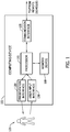
- FIG. 1 is a block diagram of an exemplary computing device 105 that may be used to monitor and/or control the operation of a portion of an electric power system (not shown in FIG. 1 ).
- Computing device 105 includes a memory device 110 and a processor 115 operatively coupled to memory device 110 for executing instructions.
- processor includes any suitable programmable circuit such as, without limitation, one or more systems and microcontrollers, microprocessors, a general purpose central processing unit (CPU), reduced instruction set circuits (RISC), application specific integrated circuits (ASIC), programmable logic circuits (PLC), field programmable gate arrays (FPGA), and/or any other circuit capable of executing the functions described herein.
- CPU central processing unit
- RISC reduced instruction set circuits
- ASIC application specific integrated circuits
- PLC programmable logic circuits
- FPGA field programmable gate arrays
- Processor 115 may include one or more processing units (e.g., in a multi-core configuration). In some embodiments, executable instructions are stored in memory device 110. Computing device 105 is configurable to perform one or more operations described herein by programming processor 115. For example, processor 115 may be programmed by encoding an operation as one or more executable instructions and providing the executable instructions in memory device 110.
- memory device 110 is at least one device coupled to processor 115 that enables storage and retrieval of information such as computer-executable instructions and data, including, without limitation, operating data, parameters, setpoints, threshold values, and/or any other data that enables computing device 105 to function as described herein.
- Memory device 110 may include one or more tangible, non-transitory, computer readable media, such as, without limitation, random access memory (RAM), dynamic random access memory (DRAM), static random access memory (SRAM), a solid state disk, a hard disk, read-only memory (ROM), erasable programmable ROM (EPROM), electrically erasable programmable ROM (EEPROM), and/or non-volatile RAM (NVRAM) memory.
- RAM random access memory
- DRAM dynamic random access memory
- SRAM static random access memory
- ROM read-only memory
- EPROM erasable programmable ROM
- EEPROM electrically erasable programmable ROM
- NVRAM non-volatile RAM
- the terms "software” and “firmware” are interchangeable, and include any computer program stored in memory for execution by personal computers, workstations, clients and servers.
- Memory device 110 may be configured to store operational measurements including, without limitation, utility electric power grid voltage and current readings (not shown in FIG. 1 ), substation voltage and current readings (not shown in FIG. 1 ), localized voltage and current readings throughout an electric power generation system (not shown in FIG. 1 ), and/or any other type of data.
- processor 115 removes or "purges" data from memory device 110 based on the age of the data. For example, processor 115 may overwrite previously recorded and stored data associated with a subsequent time and/or event. In addition, or alternatively, processor 115 may remove data that exceeds a predetermined time interval.
- memory device 110 includes, without limitation, sufficient data, algorithms, and commands to facilitate centralized and distributed control of electric power system protection and control systems (discussed further below).
- computing device 105 includes a presentation interface 120 coupled to processor 115.
- Presentation interface 120 presents information, such as a user interface and/or an alarm, to a user 125.
- presentation interface 120 includes a display adapter (not shown) that is coupled to a display device (not shown), such as a cathode ray tube (CRT), a liquid crystal display (LCD), an organic LED (OLED) display, and/or an "electronic ink" display.
- presentation interface 120 includes one or more display devices.
- presentation interface 120 includes an audio output device (not shown) (e.g., an audio adapter and/or a speaker) and/or a printer (not shown).
- presentation interface 120 presents an alarm associated with a synchronous machine (not shown in FIG. 1 ), such as by using a human machine interface (HMI) (not shown).
- HMI human machine interface
- computing device 105 includes a user input interface 130.
- user input interface 130 is coupled to processor 115 and receives input from user 125.
- User input interface 130 may include, for example, a keyboard, a pointing device, a mouse, a stylus, a touch sensitive panel (e.g., a touch pad or a touch screen), and/or an audio input interface (e.g., including a microphone).
- a single component, such as a touch screen, may function as both a display device of presentation interface 120 and user input interface 130.
- a communication interface 135 is coupled to processor 115 and is configured to be coupled in communication with one or more other devices, such as a sensor or another computing device 105, and to perform input and output operations with respect to such devices.
- communication interface 135 may include, without limitation, a wired network adapter, a wireless network adapter, a mobile telecommunications adapter, a serial communication adapter, and/or a parallel communication adapter.
- Communication interface 135 may receive data from and/or transmit data to one or more remote devices. For example, a communication interface 135 of one computing device 105 may transmit an alarm to the communication interface 135 of another computing device 105.
- Presentation interface 120 and/or communication interface 135 are both capable of providing information suitable for use with the methods described herein (e.g., to user 125 or another device). Accordingly, presentation interface 120 and communication interface 135 may be referred to as output devices. Similarly, user input interface 130 and communication interface 135 are capable of receiving information suitable for use with the methods described herein and may be referred to as input devices.
- FIG. 2 is block diagram of a portion of an exemplary electric power system protection and control system 200 that may be used to monitor and/or operate at least a portion of an electric power system 205.
- Electric power system protection and control system 200 includes an electric power system protection and control system controller 215 that may be coupled to other devices 220 via a communication network 225.
- Protection and control system controller 215 may be, without limitation, a substation-level centralized controller, a wind turbine-level centralized controller, and one of a plurality of distributed controllers.
- Embodiments of network 225 may include operative coupling with, without limitation, the Internet, a local area network (LAN), a wide area network (WAN), a wireless LAN (WLAN), and/or a virtual private network (VPN). While certain operations are described below with respect to particular computing devices 105, it is contemplated that any computing device 105 may perform one or more of the described operations. For example, controller 215 may perform all of the operations below.
- controller 215 is a computing device 105.
- computing device 105 is coupled to network 225 via communication interface 135.
- controller 215 is integrated with other devices 220.
- the term "computer” and related terms, e.g., “computing device”, are not limited to integrated circuits referred to in the art as a computer, but broadly refers to a microcontroller, a microcomputer, a programmable logic controller (PLC), an application specific integrated circuit, and other programmable circuits (none shown in FIG. 2 ), and these terms are used interchangeably herein.
- PLC programmable logic controller
- Controller 215 interacts with a first operator 230 (e.g., via user input interface 130 and/or presentation interface 120). In one embodiment, controller 215 presents information about electric power system 205, such as alarms, to operator 230. Other devices 220 interact with a second operator 235 (e.g., via user input interface 130 and/or presentation interface 120). For example, other devices 220 present alarms and/or other operational information to second operator 235.
- the term "operator” includes any person in any capacity associated with operating and maintaining electric power system 205, including, without limitation, shift operations personnel, maintenance technicians, and system supervisors.
- protection and control system 200 includes one or more monitoring sensors 240.
- Monitoring sensors 240 collect operational measurements including, without limitation, voltage and current readings throughout electric power system 205, including, without limitation, substation and wind turbine generator readings, and/or any other type of data. Monitoring sensors 240 repeatedly (e.g., periodically, continuously, and/or upon request) transmit operational measurement readings at the time of measurement. Controller 215 receives and processes the operational measurement readings. Also, controller 215 includes, without limitation, sufficient data, algorithms, and commands to facilitate centralized and/or distributed protection and control of electric power system 205 (discussed further below).
- electric power system 205 includes additional monitoring sensors (not shown) similar to monitoring sensors 240 that collect operational data measurements associated with the remainder of electric power system 205 including, without limitation, data from additional devices similar to controller 215 and environmental data, including, without limitation, local outside temperatures.
- data is transmitted across network 225 and may be accessed by any device capable of accessing network 225 including, without limitation, desktop computers, laptop computers, and personal digital assistants (PDAs) (neither shown).
- PDAs personal digital assistants
- non-transitory computer-readable media includes all tangible, computer-readable media, such as a firmware, physical and virtual storage, CD-ROMs, DVDs and another digital source such as a network or the Internet, as well as yet to be developed digital means, with the sole exception being a transitory, propagating signal.
- FIG. 3 is a schematic view of an exemplary wind turbine generator 300.
- Wind turbine generator 300 is an electric power generation device including a nacelle 302 housing a generator (not shown in FIG. 3 ). Nacelle 302 is mounted on a tower 304 (a portion of tower 304 being shown in FIG. 3 ). Tower 304 may be any height that facilitates operation of wind turbine generator 300 as described herein.
- Wind turbine generator 300 also includes a rotor 306 that includes three rotor blades 308 attached to a rotating hub 310.
- wind turbine generator 300 includes any number of blades 308 that facilitates operation of wind turbine generator 300 as described herein.
- wind turbine generator 300 includes a gearbox (not shown in FIG. 3 ) rotatably coupled to rotor 306 and the generator.
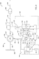
- FIG. 4 is a schematic view of an exemplary electric power system 400 for a doubly fed induction generator (DFIG) 402 that may be used with wind turbine 300.
- Electric power system 400 is a three-phase system and only one phase is shown for clarity.
- DFIG 402 includes a generator stator 404 extending about a generator rotor 406.
- Stator 404 is coupled to a stator bus 408.
- a stator-synchronizing switch 410 couples stator bus 408 to a line bus 412 when switch 410 is closed.
- a grid circuit breaker 414 couples line bus 412 to a main transformer bus 416 when breaker 414 is closed.
- Main transformer bus 416 is coupled to a main transformer 418 that couples electric power system 400 to an electric power grid 420.
- Stator 404 generates, and stator bus 408 transmits, three-phase electric power.
- electric power system 400 includes an electric power converter 422.
- Electric power converter 422 includes a generator side portion 424 coupled to a line side portion 426 through a direct current (DC) link 428.
- DC link 428 includes at least one capacitive device 430 coupled to a positive DC bus 432 and a negative DC bus 434.
- Generator side portion 424 is coupled to generator rotor 406 through an AC rotor bus 436 that includes at least one inductive device 438.
- line side portion 426 is coupled to line bus 412 through an AC line bus 440 that includes at least one inductive device 442.
- AC rotor bus 436 transmits three-phase electric power to and from generator rotor 406 and AC line bus 440 transmits three-phase electric power to and from line bus 412.
- Each of generator side portion 424 and line side portion 426 of electric power converter 422 includes a plurality of semiconductor switching devices 444 (only one switching device 444 shown in each portion 424 and 426) coupled together in serial arrangement for each phase of electrical power that electric power converter 422 receives, converts, and transmits.
- switching devices 444 are semiconductor devices, e.g., insulated gate bipolar transistors (IGBTs), that include base, emitter, and collector portions (not shown) and an inverse, or anti-parallel diode 446.
- switching devices 444 are any other suitable transistor or any other suitable switching device, including, without limitation, gate turn-off thyristors (GTOs).
- GTOs gate turn-off thyristors
- generator side portion 424 and line side portion 426 may include any suitable number of switching devices 444 arranged in any suitable configuration.
- electric power system 400 includes a plurality of protective devices and systems.
- a crowbar circuit 450 is coupled to AC rotor bus 436.
- Crowbar circuit 450 includes a plurality of switching devices 452 coupled in series with a resistor bank 454.
- Switching devices 452 are any switching devices that enable operation of crowbar circuit 450 as described herein, including, without limitation, GTOs and IGBTs. In operation, crowbar circuit 450 shorts AC rotor bus 436 to resistor bank 454 to rapidly de-energize generator side portion 424 of electric power converter 422.
- electric power system 400 includes a virtual crowbar system 460 coupled to positive DC bus 432 and negative DC bus 434.
- Virtual crowbar system 460 includes generator side portion 424 coupled in series with a resistor bank 452 through an isolation device, e.g., a circuit breaker (not shown). In operation, virtual crowbar system 460 shorts AC rotor bus 436 to resistor bank 462 to rapidly de-energize generator side portion 424 of electric power converter 422.
- electric power system 400 includes a DC dynamic brake 470 coupled to positive DC bus 432 and negative DC bus 434.
- DC dynamic brake 470 includes at least one switching device 472 coupled in series with at least one resistor 474.
- Switching device 472 is any switching device that enables operation of DC dynamic brake 470 as described herein, including, without limitation, GTOs and IGBTs. In operation, switching device 472 couples DC bus 432 and negative DC bus 434 to resistor 474 to rapidly de-energize generator side portion 424 and line side portion 426 of electric power converter 422.
- electric power system 400 includes any combination of crowbar circuit 450, virtual crowbar system 460, and DC dynamic brake 470 that enables operation of system 400 as described herein.
- electric power system 400 includes electric power system protection and control system controller 215.
- Controller 215 is coupled to, and controls the operation of, semiconductor switching devices 444 in generator side portion 424 and line side portion 426, switching devices 452, and switching device 472. Therefore, controller 215 controls the operation of generator side portion 424, line side portion 426, crowbar circuit 450, virtual crowbar system 460, and DC dynamic brake 470.
- electric power system 400 includes a virtual dynamic braking system 480.
- Virtual dynamic braking system 480 includes line side portion 426 of electric power converter 422, inductive device 442, and controller 215. Therefore, controller 215 controls the operation of line side portion 426 through controlling switching devices 444 therein.
- controller 215 is a centralized controller for the entirety of electric power system protection and control system 200, including, without limitation, virtual dynamic braking system 480.
- controller 215 is a portion of a distributed control scheme, wherein, in some embodiments, controller 215 is a standalone virtual dynamic braking controller.
- virtual dynamic braking system 480 includes at least one monitoring sensor 240 (shown in FIG.
- virtual dynamic braking system 480 includes at least one monitoring sensor 240 coupled to an electrical conductor, i.e., DC link 428, and controller 215, wherein monitoring sensor 240 measures voltages and currents on DC link 428.
- Electric power dissipation through switching devices 444 and diodes 446 of line side portion 426 is facilitated by, and is proportional to, switching losses of such devices 444 and diodes 446.
- the switching losses are a function of a switching frequency of devices 444, i.e., as the switching frequency increases, the switching losses increase. Therefore, electric power dissipation by converting stored electric energy to heat energy is performed through switching devices 444 and diodes 446.
- An upper limit of the switching frequency is at least partially determined based on the temperature ratings of devices 444 and diodes 446.
- P Core represents the core power losses of AC line bus 440 and inductive devices 442 that are a function of variables that include, without limitation, the frequency and the peak voltage of the electricity transmitted therethrough.
- P Core is also a function of steady-state features that include, without limitation, the physical dimensions of inductive devices 442, the material used to fabricate inductive devices 442, and the number of turns in inductive devices 442.
- P DCR represents the power losses due to DC resistances of line bus 440 and inductive devices 442.
- P ACR represents the power losses due to AC resistances of line bus 440 and inductive devices 442.
- Such AC resistances are at least partially based on the "skin effect" and the "proximity effect” associated with AC conductors.
- the skin effect is defined as the tendency of an AC current to distribute itself within a conductor with the current density being greatest near the surface of the conductor and decreasing as the depth increases. As the AC current is shifted to the outer portions of the conductor, the apparent resistance of the conductor increases.
- the proximity effect is defined as the tendency for nearby conductors to affect the current density within each of the conductors as a function of the strength of the electromagnetic fields induced by each. For example, for adjacent conductors transmitting current in the same direction, the currents will be shifted away from the adjacent conductor.
- P Fringing represents the power losses due to magnetic reluctances in air gaps (not shown) between turns (not shown) in inductive devices 442.
- air gap reluctances induce a bulging, or fringing magnetic field that includes a leakage flux in each air gap that induces an increased resistance to current transmission therethrough.
- the magnitude of such leakage flux is at least partially dependent on the frequency of the current transmitted through inductive devices 442. Therefore, increasing the frequency of the current through inductive devices 442 increases the leakage flux and the fringing field power losses.
- stator 404 of DFIG 402 In operation, sinusoidal three-phase AC electric power generated by stator 404 of DFIG 402 is transmitted to electric power grid 420 through stator bus 408, stator synchronizing switch 410, line bus 412, grid circuit breaker 414, main transformer bus 416, and main transformer 418.
- the relative speeds between generator rotor 406 and generator stator 404 determines operation of electric power converter 422.
- electric power converter 422 excites generator rotor 406 with reactive power transmitted from generator side portion 424 through AC rotor bus 436.
- Generator rotor 406 will then appear to be turning at a synchronous speed with respect to generator stator 404 and stator 404 will generate the desired, i.e., synchronous frequency, electric power that is transmitted to electric power grid 420 as described above.
- electric power converter 422 excites generator rotor 406 with real power transmitted from generator side portion 424 through AC rotor bus 436.
- Generator stator 404 generates electric power at the synchronous frequency that is transmitted to electric power grid 420 as described above.
- electric power converter 422 excites generator rotor 406 with reactive power transmitted from generator side portion 424 through AC rotor bus 436 while at the same time extracting real power from generator rotor 406 through AC rotor bus 436 to generator side portion 424.
- Generator rotor 406 will then appear to be turning at a synchronous speed with respect to generator stator 404 and stator 404 will generate electric power at the synchronous frequency that is transmitted to electric power grid 420 as described above.
- the frequency of the power extracted from generator rotor 406 will be converted to the synchronous frequency through electric power converter 422 and the rotor-generated electric power is added to the stator-generated power.
- line side portion 426 of electric power converter 422 is synchronized with the frequency on line bus 412, typically a substantially constant 60 Hertz (Hz).
- the synchronous frequency is any frequency that enables operation of electric power system 400 and protection and control system 200 as described herein, including, without limitation, 50 Hz. Therefore, switching devices 444 of line side portion 426 are switching at a switching rate that enables a synchronous frequency of 60 Hz.
- controller 215 uses one or more non-transitory computer-readable storage media having computer-executable instructions embodied thereon, wherein when executed by processor 115 (shown in FIG. 1 ), the computer-executable instructions cause processor 115 to operate switching devices 444 in line side portion 426 at a first predetermined frequency, e.g., 60 Hz, to convert DC power to AC power for transmission to electric power grid 420.
- a first predetermined frequency e.g. 60 Hz
- controller 215 regulates the inductive properties, and therefore the power losses, of inductive devices 442 and AC line bus 440 such that a predetermined value of current is transmitted from an electrical conductor, i.e., positive DC bus 432 and negative DC bus 434 of DC link 428 to grid 420 as a function of a measured voltage on DC link 428.
- an electrical conductor i.e., positive DC bus 432 and negative DC bus 434 of DC link 428 to grid 420 as a function of a measured voltage on DC link 428.
- electric power system 400 may experience electrical disturbances.
- electric power system 400 may experience an overvoltage condition on DC link 428.
- overvoltage conditions may be induced by grid fault events, e.g., low-voltage ride through (LVRT) and zero-voltage ride-through (ZVRT) transients.
- LVRT low-voltage ride through
- ZVRT zero-voltage ride-through
- virtual dynamic braking system 480 is selectively activated based on the value of DC voltage on DC link 428.
- controller 215 uses one or more non-transitory computer-readable storage media having computer-executable instructions embodied thereon, wherein when executed by processor 115, the computer-executable instructions cause processor 115 to operate switching devices 444 in line side portion 426 with at least one second predetermined frequency that is greater than 60 Hz to convert DC power to AC power for transmission through line side portion 426 to inductive devices 442 and AC line bus 440.
- controller 215 regulates the inductive properties, and therefore, the power losses, of inductive devices 442 and AC line bus 440 such that a predetermined value of current is transmitted from an electrical conductor, i.e., positive DC bus 432 and negative DC bus 434 of DC link 428 as a function of a measured voltage on DC link 428.
- an electrical conductor i.e., positive DC bus 432 and negative DC bus 434 of DC link 428 as a function of a measured voltage on DC link 428.
- the increased frequency of electric current generated by line side portion 426 induces power dissipation through inductive devices 442 and AC line bus 440 at a predetermined rate that is a function of the frequencies of the power generated by portion 426 and the inductive properties of devices 442 and bus 440, as well as the heat generation properties of switching devices 444 and diodes 446.
- Operation of virtual dynamic braking system 480 may be coupled with operation of crowbar circuit 450, virtual crowbar system 460, and DC dynamic brake 470, as well as the LVRT and ZVRT features of protection and control system 200 and electric power system 400.
- Such cooperative operation facilitates measuring and controlling voltage values on DC link 428, AC line bus 440, grid 420, and measuring and controlling current values transmitted through AC line bus 440.
- FIG. 5 is a schematic view of an exemplary alternative electric power system 500 that may be used with wind turbine 300, wherein wind turbine 300 includes a gearbox 501 rotatably coupled to a low speed shaft 503 and a high speed shaft 505.
- a generator 502 is rotatably coupled to high speed shaft 505.
- generator 502 is any type of generator that enables operation of wind turbine generator 300 as described herein, including, without limitation, a synchronous permanent magnet generator (PMG) and an electrically excited synchronous generator (EESG).
- Gearbox 501 steps-up a rotational velocity of low speed shaft 503 to attain a rotational velocity of high speed shaft 505 that is closer to synchronous speed.
- electric power system 500 is a three-phase system.
- Generator 502 includes a generator stator 504 extending about a generator rotor 506 that is rotatably coupled to high speed shaft 505.
- Stator 504 is coupled to a stator bus 508 through a plurality of inductive devices 507.
- Stator bus 508 is coupled to an electric power converter 522.
- Electric power converter 522 includes a generator side portion 524 coupled to stator bus 508.
- Generator side portion 524 is coupled to a line side portion 526 through a DC link 528.
- DC link 528 includes at least one capacitive device 530 coupled to a positive DC bus 532 and a negative DC bus 534.
- Line side portion 526 is coupled to an AC line bus 540 that includes at least one inductive device 542.
- Stator bus 508 transmits three-phase electric power to generator side portion 524 and AC line bus 540 transmits three-phase electric power away from line side portion 526.
- Each of generator side portion 524 and line side portion 526 of electric power converter 522 includes a plurality of semiconductor switching devices 544 coupled together in serial arrangement for each phase of electrical power that electric power converter 522 receives, converts, and transmits.
- switching devices 544 are semiconductor devices, e.g., insulated gate bipolar transistors (IGBTs), that include base, emitter, and collector portions (not shown) and an inverse, or anti-parallel diode 546.
- switching devices 544 are any other suitable transistor or any other suitable switching device, including, without limitation, gate turn-off thyristors (GTOs).
- GTOs gate turn-off thyristors
- generator side portion 524 and line side portion 526 may include any suitable number of switching devices 544 arranged in any suitable configuration.
- a stator-synchronizing switch 517 couples AC line bus 540 to a main transformer 518 that couples electric power system 500 to an electric power grid 520 when switch 517 is closed.
- electric power system 500 includes any combination of plurality of protective devices and systems that enable operation of system 500 as described herein.
- Such devices may include a crowbar circuit similar to crowbar circuit 450 (shown in FIG. 4 ), a virtual crowbar system similar to virtual crowbar system 460 (shown in FIG. 4 ), and a DC dynamic brake similar to DC dynamic brake 470 (shown in FIG. 4 ).
- electric power system 500 includes electric power system protection and control system controller 215.
- Controller 215 is coupled to, and controls the operation of, semiconductor switching devices 544 in generator side portion 524 and line side portion 526. Therefore, controller 215 controls the operation of generator side portion 524 and line side portion 526.
- electric power system 500 includes a dynamic braking system 580.
- Dynamic braking system 580 includes line side portion 526 of electric power converter 522, inductive devices 542, and controller 215. Therefore, controller 215 controls the operation of line side portion 526 through controlling switching devices 544 therein.
- controller 215 is a centralized controller for the entirety of electric power system protection and control system 200.
- controller 215 is a portion of a distributed control scheme, wherein, in some embodiments, controller 215 is a standalone dynamic brake controller.
- dynamic braking system 580 includes at least one monitoring sensor 240 (shown in FIG.
- dynamic braking system 580 includes at least one monitoring sensor 240 coupled to an electrical conductor, i.e., DC link 528 and controller 215, wherein monitoring sensor 240 measures voltages and currents on DC link 528.
- Electric power dissipation through virtual dynamic braking system 580 is substantially similar to that for virtual dynamic braking system 480 (shown in FIG. 4 ).
- a combination of electric power generation devices are used in conjunction with, or in place of, wind turbine generator 300.
- wind turbine generator 300 is replaced with solar panels (not shown) coupled to form one or more solar arrays (not shown) to facilitate operating at a desired power output with supplemental, solar-generated power.
- Solar panels include, in one alternative embodiment, one or more of a photovoltaic panel, a solar thermal collector, or any other device that converts solar energy to electrical energy.
- each solar panel is a photovoltaic panel that generates a substantially direct current power as a result of solar energy striking solar panels.
- each solar array is coupled to a power converter that is similar to at least a portion of electric power converter 522 converts the DC power to AC power that is transmitted to a transformer, similar to main transformer 518, and then subsequently to grid 520.
- a power converter that is similar to at least a portion of electric power converter 522 converts the DC power to AC power that is transmitted to a transformer, similar to main transformer 518, and then subsequently to grid 520.
- the methods and systems described herein are applicable to any type of electric generation system, with or without a power converter, including, for example, fuel cells, thermal power generators, geothermal generators, hydropower generators, diesel generators, gasoline generators, and/or any other device that generates power from renewable and/or non-renewable energy sources.
- Exemplary embodiments of an electric power system and methods for operating the same are described above in detail.
- the methods and systems are not limited to the specific embodiments described herein, but rather, components of the systems and/or steps of the methods may be utilized independently and separately from other components and/or steps described herein.
- the power converters, virtual dynamic braking systems, and methods may also be used in combination with other power conversion apparatus and methods, and are not limited to practice with only the electric power systems as described herein. Rather, the exemplary embodiment can be implemented and utilized in connection with many other electric power conversion applications.
Landscapes
- Engineering & Computer Science (AREA)
- Power Engineering (AREA)
- Life Sciences & Earth Sciences (AREA)
- Sustainable Development (AREA)
- Sustainable Energy (AREA)
- Chemical & Material Sciences (AREA)
- Combustion & Propulsion (AREA)
- Mechanical Engineering (AREA)
- General Engineering & Computer Science (AREA)
- Control Of Eletrric Generators (AREA)
Applications Claiming Priority (1)
| Application Number | Priority Date | Filing Date | Title |
|---|---|---|---|
| PCT/CN2012/078543 WO2014008647A1 (en) | 2012-07-12 | 2012-07-12 | Dynamic braking system for an electric power system and method of operating the same |
Publications (3)
| Publication Number | Publication Date |
|---|---|
| EP2873151A1 EP2873151A1 (en) | 2015-05-20 |
| EP2873151A4 EP2873151A4 (en) | 2016-07-27 |
| EP2873151B1 true EP2873151B1 (en) | 2021-08-25 |
Family
ID=49915323
Family Applications (1)
| Application Number | Title | Priority Date | Filing Date |
|---|---|---|---|
| EP12880768.2A Active EP2873151B1 (en) | 2012-07-12 | 2012-07-12 | Electric power system and method of operating the same |
Country Status (6)
| Country | Link |
|---|---|
| US (1) | US9369076B2 (es) |
| EP (1) | EP2873151B1 (es) |
| AU (1) | AU2012385428B2 (es) |
| CA (1) | CA2878612C (es) |
| ES (1) | ES2898769T3 (es) |
| WO (1) | WO2014008647A1 (es) |
Families Citing this family (17)
| Publication number | Priority date | Publication date | Assignee | Title |
|---|---|---|---|---|
| WO2014008647A1 (en) * | 2012-07-12 | 2014-01-16 | General Electric Company | Dynamic braking system for an electric power system and method of operating the same |
| EP2875238B1 (en) * | 2012-07-19 | 2019-02-20 | Vestas Wind Systems A/S | A method of operating a wind turbine as well as a system suitable thereof |
| CN103956771A (zh) * | 2014-04-30 | 2014-07-30 | 上海电机学院 | 低电压穿越系统 |
| US9467081B2 (en) * | 2014-09-29 | 2016-10-11 | Ingeteam Power Technology, S.A. | Protection system for a power converter connected to a doubly fed induction generator |
| JP2016103968A (ja) * | 2014-10-21 | 2016-06-02 | ゼネラル・エレクトリック・カンパニイ | 送電網損失ライドスルー機能を有する誘導発電機システム |
| CN104362674B (zh) * | 2014-10-31 | 2016-08-24 | 国家电网公司 | 一种基于安全运行电压的双馈风电机组高电压穿越方法 |
| US9960686B2 (en) * | 2014-11-17 | 2018-05-01 | Infineon Technologies Austria Ag | System and method for detecting a loss of AC power in a switched-mode power supply |
| US10050433B2 (en) | 2014-12-11 | 2018-08-14 | General Electric Company | Power generation system and method with resistive braking capability |
| US10185295B2 (en) * | 2015-09-30 | 2019-01-22 | Osram Sylvania Inc. | Dynamic control of switching frequency in a switch mode power converter |
| PL3157161T3 (pl) | 2015-10-12 | 2019-09-30 | Siemens Aktiengesellschaft | Sposób sterowania instalacją energii wiatrowej |
| CN105470990B (zh) * | 2016-01-08 | 2018-09-18 | 镇江华东电力设备制造厂有限公司 | 大功率直驱式永磁风力发电系统低压穿越控制系统及控制方法 |
| US10063172B2 (en) * | 2016-12-27 | 2018-08-28 | General Electric Company | Controlled braking of a generator |
| US10103663B1 (en) | 2017-04-18 | 2018-10-16 | General Electric Company | Control method for protecting switching devices in power converters in doubly fed induction generator power systems |
| US10886726B2 (en) | 2017-09-15 | 2021-01-05 | General Electric Company | Control method for protecting transformers |
| US10819103B2 (en) * | 2017-12-07 | 2020-10-27 | General Electric Company | Systems and methods for isolating faults in electrical power systems connected to a power grid |
| US10615727B2 (en) * | 2018-08-27 | 2020-04-07 | General Electric Company | Dynamic brake circuit assembly for a wind turbine |
| CN118763794A (zh) * | 2024-06-06 | 2024-10-11 | 芜湖睿扬信息科技有限公司 | 一种基于物联网的电力系统实时动态监测方法及系统 |
Citations (2)
| Publication number | Priority date | Publication date | Assignee | Title |
|---|---|---|---|---|
| US20080130321A1 (en) * | 2006-12-01 | 2008-06-05 | Artusi Daniel A | Power converter with an adaptive controller and method of operating the same |
| EP2424101A2 (en) * | 2010-08-28 | 2012-02-29 | General Electric Company | Power inverter system and method of starting same at high DC voltage |
Family Cites Families (56)
| Publication number | Priority date | Publication date | Assignee | Title |
|---|---|---|---|---|
| US3657625A (en) * | 1969-11-24 | 1972-04-18 | Westinghouse Electric Corp | System for blending dynamic and regenerative braking |
| US3819998A (en) * | 1972-05-16 | 1974-06-25 | Xerox Corp | Dynamic braking control system |
| US3774095A (en) * | 1972-09-20 | 1973-11-20 | Westinghouse Air Brake Co | System for blending regenerative and dynamic and friction braking |
| US4481449A (en) * | 1982-09-17 | 1984-11-06 | Ampex Corporation | Power fail servo system |
| US4672298A (en) * | 1983-05-06 | 1987-06-09 | Frederick Rohatyn | Power factor correction system |
| US4767970A (en) * | 1986-12-22 | 1988-08-30 | Ampex Corporation | Dynamic brake control for a tape drive system |
| US4761600A (en) | 1987-03-06 | 1988-08-02 | General Electric Company | Dynamic brake control |
| US5198745A (en) | 1991-08-08 | 1993-03-30 | Electric Power Research Institute | Dynamic braking resistor system |
| US5998880A (en) * | 1997-08-07 | 1999-12-07 | General Electric Company | AC locomotive operation without DC current sensor |
| FR2801444B1 (fr) * | 1999-11-24 | 2002-02-08 | Dassault Aviat | Generateur electrique autonome, notamment pour aeronef |
| US6486568B1 (en) * | 1999-12-21 | 2002-11-26 | General Electric Company | Power system using a multi-functional power interface unit |
| TWI221806B (en) | 2001-10-19 | 2004-10-11 | Sumitomo Heavy Industries | Injection molding machine and method of protecting the injection molding machine |
| EA006363B1 (ru) * | 2002-05-16 | 2005-12-29 | Млх Глобал Корпорэйшен Инк. | Ветротурбина с гидравлической трансмиссией |
| EP1499009B1 (en) * | 2003-07-15 | 2007-10-31 | Gamesa Innovation & Technology, S.L. Unipersonal | Control and protection of a doubly-fed induction generator system |
| DK1728304T3 (da) * | 2004-03-12 | 2010-08-23 | Gen Electric | Fremgangsmåde til drift af en frekvenskonverter af en generator og vindmølle, som har en generator, der drives i henhold til fremgangsmåden |
| WO2006069569A1 (en) | 2004-12-28 | 2006-07-06 | Vestas Wind Systems A/S | Method of controlling a wind turbine connected to an electric utility grid |
| US7126236B2 (en) * | 2005-03-15 | 2006-10-24 | General Electric Company | Methods and apparatus for pitch control power conversion |
| US7923965B2 (en) * | 2005-10-10 | 2011-04-12 | General Electric Company | Methods for coupling an energy storage system to a variable energy supply system |
| US7423412B2 (en) | 2006-01-31 | 2008-09-09 | General Electric Company | Method, apparatus and computer program product for injecting current |
| US7425771B2 (en) * | 2006-03-17 | 2008-09-16 | Ingeteam S.A. | Variable speed wind turbine having an exciter machine and a power converter not connected to the grid |
| CN101401294B (zh) | 2006-03-17 | 2013-04-17 | 英捷电力技术有限公司 | 具有激励器设备和不连接至电网的功率变换器的变速风机 |
| US7919879B2 (en) | 2006-05-31 | 2011-04-05 | Wisconsin Alumni Research Foundation | Power conditioning architecture for a wind turbine |
| US7586216B2 (en) * | 2006-06-02 | 2009-09-08 | General Electric Company | Redundant electrical brake and protection system for electric generators |
| CA2655334C (en) * | 2006-06-13 | 2014-08-05 | Railpower Technologies Corp. | Load-lifting apparatus and method of storing energy for the same |
| EP2122821A1 (en) * | 2007-02-26 | 2009-11-25 | Newcastle Innovation Limited | Integrated wind turbine controller and inverter |
| JP4501958B2 (ja) * | 2007-05-09 | 2010-07-14 | 株式会社日立製作所 | 風力発電システムおよびその制御方法 |
| US7573732B2 (en) * | 2007-05-25 | 2009-08-11 | General Electric Company | Protective circuit and method for multi-level converter |
| JP2008301584A (ja) * | 2007-05-30 | 2008-12-11 | Hitachi Ltd | 風力発電システムおよび電力変換器の制御方法 |
| US7466109B1 (en) * | 2008-04-07 | 2008-12-16 | General Electric Company | Systems and methods involving variable speed generators |
| US7786608B2 (en) | 2008-11-17 | 2010-08-31 | General Electric Company | Protection system for wind turbine |
| US8203229B2 (en) * | 2009-06-15 | 2012-06-19 | Challenger Design, LLC | Auxiliary drive/brake system for a wind turbine |
| US20100314881A1 (en) * | 2009-06-15 | 2010-12-16 | Challenger Design Llc | Auxiliary drive/brake system for a wind turbine |
| US8587160B2 (en) * | 2009-09-04 | 2013-11-19 | Rockwell Automation Technologies, Inc. | Grid fault ride-through for current source converter-based wind energy conversion systems |
| US8080891B2 (en) * | 2009-09-25 | 2011-12-20 | General Electric Company | Hybrid braking system and method |
| US7942631B2 (en) * | 2009-10-26 | 2011-05-17 | General Electric Company | Method and apparatus for powering a pitch control system |
| US8018082B2 (en) * | 2009-11-25 | 2011-09-13 | General Electric Company | Method and apparatus for controlling a wind turbine |
| US7978445B2 (en) | 2009-12-31 | 2011-07-12 | General Electric Company | Systems and apparatus relating to wind turbine electrical control and operation |
| CN101860043B (zh) * | 2010-05-17 | 2012-09-19 | 东南大学 | 串联型风力发电机组低电压穿越控制装置及控制方法 |
| US8013461B2 (en) * | 2010-06-22 | 2011-09-06 | General Electric Company | Power conversion system and method for a rotary power generation system |
| DK2405134T3 (da) * | 2010-07-06 | 2013-05-27 | Ge Energy Power Conversion Technology Ltd | Drejningsmomentstyringsfremgangsmåde for generator |
| US8093741B2 (en) * | 2010-10-29 | 2012-01-10 | General Electric Company | Method and system for providing increased turbine output for doubly fed induction generator |
| US8344550B2 (en) * | 2010-12-21 | 2013-01-01 | General Electric Company | Power conversion control with energy storage |
| CN102055208B (zh) | 2010-12-31 | 2013-01-16 | 清华大学 | 一种用于双馈式风力发电系统的低压穿越控制方法 |
| US8432054B2 (en) * | 2011-06-13 | 2013-04-30 | Wind Smart, Inc. | Wind turbine with hydrostatic transmission |
| US8258642B2 (en) * | 2011-09-27 | 2012-09-04 | General Electric Company | Method and system for resonance dampening in wind turbines |
| US20140219802A1 (en) * | 2011-10-05 | 2014-08-07 | Viggo Lundhild | Vertical Axis Wind\Tidal Turbine with Dynamically Positioned Blades |
| US8907510B2 (en) * | 2012-03-09 | 2014-12-09 | General Electric Company | Method and systems for operating a wind turbine |
| US9041234B2 (en) * | 2012-03-26 | 2015-05-26 | Rockwell Automation Technologies, Inc. | Double fed induction generator (DFIG) converter and method for improved grid fault ridethrough |
| US9312682B2 (en) * | 2012-05-14 | 2016-04-12 | General Electric Company | System and method for overvoltage protection |
| US20130334818A1 (en) * | 2012-06-19 | 2013-12-19 | Clipper Windpower, LLC. | Dynamic Braking on a Wind Turbine During a Fault |
| WO2014008647A1 (en) * | 2012-07-12 | 2014-01-16 | General Electric Company | Dynamic braking system for an electric power system and method of operating the same |
| US9115694B2 (en) * | 2012-08-27 | 2015-08-25 | General Electric Company | Wind turbine pitch control system |
| US8664788B1 (en) * | 2012-09-07 | 2014-03-04 | General Electric Company | Method and systems for operating a wind turbine using dynamic braking in response to a grid event |
| US8975768B2 (en) * | 2013-06-05 | 2015-03-10 | General Electic Company | Methods for operating wind turbine system having dynamic brake |
| WO2014201018A1 (en) * | 2013-06-10 | 2014-12-18 | Uprise Energy, LLC | Wind energy devices, systems, and methods |
| US9425726B2 (en) * | 2013-06-25 | 2016-08-23 | Masdar Institute Of Science And Technology | Fault-tolerant wind energy conversion system |
-
2012
- 2012-07-12 WO PCT/CN2012/078543 patent/WO2014008647A1/en active Application Filing
- 2012-07-12 US US14/412,389 patent/US9369076B2/en active Active
- 2012-07-12 ES ES12880768T patent/ES2898769T3/es active Active
- 2012-07-12 AU AU2012385428A patent/AU2012385428B2/en active Active
- 2012-07-12 CA CA2878612A patent/CA2878612C/en active Active
- 2012-07-12 EP EP12880768.2A patent/EP2873151B1/en active Active
Patent Citations (2)
| Publication number | Priority date | Publication date | Assignee | Title |
|---|---|---|---|---|
| US20080130321A1 (en) * | 2006-12-01 | 2008-06-05 | Artusi Daniel A | Power converter with an adaptive controller and method of operating the same |
| EP2424101A2 (en) * | 2010-08-28 | 2012-02-29 | General Electric Company | Power inverter system and method of starting same at high DC voltage |
Also Published As
| Publication number | Publication date |
|---|---|
| EP2873151A1 (en) | 2015-05-20 |
| EP2873151A4 (en) | 2016-07-27 |
| CA2878612C (en) | 2021-07-27 |
| AU2012385428B2 (en) | 2017-04-06 |
| WO2014008647A1 (en) | 2014-01-16 |
| CA2878612A1 (en) | 2014-01-16 |
| AU2012385428A1 (en) | 2015-02-05 |
| ES2898769T3 (es) | 2022-03-08 |
| US9369076B2 (en) | 2016-06-14 |
| US20150188468A1 (en) | 2015-07-02 |
Similar Documents
| Publication | Publication Date | Title |
|---|---|---|
| EP2873151B1 (en) | Electric power system and method of operating the same | |
| US9513614B2 (en) | Auxiliary electric power system and method of regulating voltages of the same | |
| US9046077B2 (en) | Reactive power controller for controlling reactive power in a wind farm | |
| US20130138257A1 (en) | System for operating an electric power system and method of operating the same | |
| US8519568B2 (en) | Inrush current protection for wind turbines and wind farms | |
| US20120136494A1 (en) | Method of controlling reactive power in a wind farm | |
| EP3058651B1 (en) | Turbine generator system with dc output | |
| US20140030089A1 (en) | Wind turbine lifetime estimator | |
| US20160341179A1 (en) | Limit for derating scheme used in wind turbine control | |
| Zhang et al. | Fault ride-through study of wind turbines | |
| US8451573B1 (en) | Overvoltage protection device for a wind turbine and method | |
| US9088150B2 (en) | Overvoltage clipping device for a wind turbine and method | |
| US8854845B2 (en) | System and method of over-voltage protection | |
| US9494139B2 (en) | System and method for controlling a power output of a wind turbine generator | |
| Yang et al. | Low-voltage ride-through strategy for offshore wind turbines based on current relaxation region | |
| US20150263508A1 (en) | System and method for detecting islanding of electrical machines and protecting same | |
| Chen et al. | A new method to improve the LVRT of DFIG based on the current compensation | |
| Tourou et al. | Power quality impact on grid-connected wind energy conversion system | |
| Mumtaz | Harmonic domain modelling of wind-based micro-grids | |
| JP2018121476A (ja) | 風力発電施設、及び、風力発電施設の運転方法 |
Legal Events
| Date | Code | Title | Description |
|---|---|---|---|
| PUAI | Public reference made under article 153(3) epc to a published international application that has entered the european phase |
Free format text: ORIGINAL CODE: 0009012 |
|
| 17P | Request for examination filed |
Effective date: 20150212 |
|
| AK | Designated contracting states |
Kind code of ref document: A1 Designated state(s): AL AT BE BG CH CY CZ DE DK EE ES FI FR GB GR HR HU IE IS IT LI LT LU LV MC MK MT NL NO PL PT RO RS SE SI SK SM TR |
|
| AX | Request for extension of the european patent |
Extension state: BA ME |
|
| DAX | Request for extension of the european patent (deleted) | ||
| D17D | Deferred search report published (deleted) | ||
| RA4 | Supplementary search report drawn up and despatched (corrected) |
Effective date: 20160627 |
|
| RIC1 | Information provided on ipc code assigned before grant |
Ipc: H02P 9/02 20060101ALI20160621BHEP Ipc: F03D 7/02 20060101ALI20160621BHEP Ipc: H02P 9/10 20060101ALI20160621BHEP Ipc: H02P 9/00 20060101AFI20160621BHEP |
|
| STAA | Information on the status of an ep patent application or granted ep patent |
Free format text: STATUS: EXAMINATION IS IN PROGRESS |
|
| 17Q | First examination report despatched |
Effective date: 20180618 |
|
| STAA | Information on the status of an ep patent application or granted ep patent |
Free format text: STATUS: EXAMINATION IS IN PROGRESS |
|
| GRAP | Despatch of communication of intention to grant a patent |
Free format text: ORIGINAL CODE: EPIDOSNIGR1 |
|
| STAA | Information on the status of an ep patent application or granted ep patent |
Free format text: STATUS: GRANT OF PATENT IS INTENDED |
|
| INTG | Intention to grant announced |
Effective date: 20210211 |
|
| GRAS | Grant fee paid |
Free format text: ORIGINAL CODE: EPIDOSNIGR3 |
|
| GRAA | (expected) grant |
Free format text: ORIGINAL CODE: 0009210 |
|
| STAA | Information on the status of an ep patent application or granted ep patent |
Free format text: STATUS: THE PATENT HAS BEEN GRANTED |
|
| AK | Designated contracting states |
Kind code of ref document: B1 Designated state(s): AL AT BE BG CH CY CZ DE DK EE ES FI FR GB GR HR HU IE IS IT LI LT LU LV MC MK MT NL NO PL PT RO RS SE SI SK SM TR |
|
| REG | Reference to a national code |
Ref country code: GB Ref legal event code: FG4D |
|
| REG | Reference to a national code |
Ref country code: CH Ref legal event code: EP |
|
| REG | Reference to a national code |
Ref country code: IE Ref legal event code: FG4D Ref country code: AT Ref legal event code: REF Ref document number: 1424832 Country of ref document: AT Kind code of ref document: T Effective date: 20210915 |
|
| REG | Reference to a national code |
Ref country code: DE Ref legal event code: R096 Ref document number: 602012076553 Country of ref document: DE |
|
| REG | Reference to a national code |
Ref country code: DK Ref legal event code: T3 Effective date: 20211124 |
|
| REG | Reference to a national code |
Ref country code: LT Ref legal event code: MG9D |
|
| REG | Reference to a national code |
Ref country code: NL Ref legal event code: MP Effective date: 20210825 |
|
| REG | Reference to a national code |
Ref country code: AT Ref legal event code: MK05 Ref document number: 1424832 Country of ref document: AT Kind code of ref document: T Effective date: 20210825 |
|
| PG25 | Lapsed in a contracting state [announced via postgrant information from national office to epo] |
Ref country code: HR Free format text: LAPSE BECAUSE OF FAILURE TO SUBMIT A TRANSLATION OF THE DESCRIPTION OR TO PAY THE FEE WITHIN THE PRESCRIBED TIME-LIMIT Effective date: 20210825 Ref country code: SE Free format text: LAPSE BECAUSE OF FAILURE TO SUBMIT A TRANSLATION OF THE DESCRIPTION OR TO PAY THE FEE WITHIN THE PRESCRIBED TIME-LIMIT Effective date: 20210825 Ref country code: LT Free format text: LAPSE BECAUSE OF FAILURE TO SUBMIT A TRANSLATION OF THE DESCRIPTION OR TO PAY THE FEE WITHIN THE PRESCRIBED TIME-LIMIT Effective date: 20210825 Ref country code: AT Free format text: LAPSE BECAUSE OF FAILURE TO SUBMIT A TRANSLATION OF THE DESCRIPTION OR TO PAY THE FEE WITHIN THE PRESCRIBED TIME-LIMIT Effective date: 20210825 Ref country code: BG Free format text: LAPSE BECAUSE OF FAILURE TO SUBMIT A TRANSLATION OF THE DESCRIPTION OR TO PAY THE FEE WITHIN THE PRESCRIBED TIME-LIMIT Effective date: 20211125 Ref country code: RS Free format text: LAPSE BECAUSE OF FAILURE TO SUBMIT A TRANSLATION OF THE DESCRIPTION OR TO PAY THE FEE WITHIN THE PRESCRIBED TIME-LIMIT Effective date: 20210825 Ref country code: PT Free format text: LAPSE BECAUSE OF FAILURE TO SUBMIT A TRANSLATION OF THE DESCRIPTION OR TO PAY THE FEE WITHIN THE PRESCRIBED TIME-LIMIT Effective date: 20211227 Ref country code: NO Free format text: LAPSE BECAUSE OF FAILURE TO SUBMIT A TRANSLATION OF THE DESCRIPTION OR TO PAY THE FEE WITHIN THE PRESCRIBED TIME-LIMIT Effective date: 20211125 Ref country code: FI Free format text: LAPSE BECAUSE OF FAILURE TO SUBMIT A TRANSLATION OF THE DESCRIPTION OR TO PAY THE FEE WITHIN THE PRESCRIBED TIME-LIMIT Effective date: 20210825 |
|
| PG25 | Lapsed in a contracting state [announced via postgrant information from national office to epo] |
Ref country code: PL Free format text: LAPSE BECAUSE OF FAILURE TO SUBMIT A TRANSLATION OF THE DESCRIPTION OR TO PAY THE FEE WITHIN THE PRESCRIBED TIME-LIMIT Effective date: 20210825 Ref country code: LV Free format text: LAPSE BECAUSE OF FAILURE TO SUBMIT A TRANSLATION OF THE DESCRIPTION OR TO PAY THE FEE WITHIN THE PRESCRIBED TIME-LIMIT Effective date: 20210825 Ref country code: GR Free format text: LAPSE BECAUSE OF FAILURE TO SUBMIT A TRANSLATION OF THE DESCRIPTION OR TO PAY THE FEE WITHIN THE PRESCRIBED TIME-LIMIT Effective date: 20211126 |
|
| REG | Reference to a national code |
Ref country code: ES Ref legal event code: FG2A Ref document number: 2898769 Country of ref document: ES Kind code of ref document: T3 Effective date: 20220308 |
|
| PG25 | Lapsed in a contracting state [announced via postgrant information from national office to epo] |
Ref country code: NL Free format text: LAPSE BECAUSE OF FAILURE TO SUBMIT A TRANSLATION OF THE DESCRIPTION OR TO PAY THE FEE WITHIN THE PRESCRIBED TIME-LIMIT Effective date: 20210825 |
|
| REG | Reference to a national code |
Ref country code: DE Ref legal event code: R097 Ref document number: 602012076553 Country of ref document: DE |
|
| PG25 | Lapsed in a contracting state [announced via postgrant information from national office to epo] |
Ref country code: SM Free format text: LAPSE BECAUSE OF FAILURE TO SUBMIT A TRANSLATION OF THE DESCRIPTION OR TO PAY THE FEE WITHIN THE PRESCRIBED TIME-LIMIT Effective date: 20210825 Ref country code: SK Free format text: LAPSE BECAUSE OF FAILURE TO SUBMIT A TRANSLATION OF THE DESCRIPTION OR TO PAY THE FEE WITHIN THE PRESCRIBED TIME-LIMIT Effective date: 20210825 Ref country code: RO Free format text: LAPSE BECAUSE OF FAILURE TO SUBMIT A TRANSLATION OF THE DESCRIPTION OR TO PAY THE FEE WITHIN THE PRESCRIBED TIME-LIMIT Effective date: 20210825 Ref country code: EE Free format text: LAPSE BECAUSE OF FAILURE TO SUBMIT A TRANSLATION OF THE DESCRIPTION OR TO PAY THE FEE WITHIN THE PRESCRIBED TIME-LIMIT Effective date: 20210825 Ref country code: CZ Free format text: LAPSE BECAUSE OF FAILURE TO SUBMIT A TRANSLATION OF THE DESCRIPTION OR TO PAY THE FEE WITHIN THE PRESCRIBED TIME-LIMIT Effective date: 20210825 Ref country code: AL Free format text: LAPSE BECAUSE OF FAILURE TO SUBMIT A TRANSLATION OF THE DESCRIPTION OR TO PAY THE FEE WITHIN THE PRESCRIBED TIME-LIMIT Effective date: 20210825 |
|
| PLBE | No opposition filed within time limit |
Free format text: ORIGINAL CODE: 0009261 |
|
| STAA | Information on the status of an ep patent application or granted ep patent |
Free format text: STATUS: NO OPPOSITION FILED WITHIN TIME LIMIT |
|
| PG25 | Lapsed in a contracting state [announced via postgrant information from national office to epo] |
Ref country code: IT Free format text: LAPSE BECAUSE OF FAILURE TO SUBMIT A TRANSLATION OF THE DESCRIPTION OR TO PAY THE FEE WITHIN THE PRESCRIBED TIME-LIMIT Effective date: 20210825 |
|
| 26N | No opposition filed |
Effective date: 20220527 |
|
| PG25 | Lapsed in a contracting state [announced via postgrant information from national office to epo] |
Ref country code: SI Free format text: LAPSE BECAUSE OF FAILURE TO SUBMIT A TRANSLATION OF THE DESCRIPTION OR TO PAY THE FEE WITHIN THE PRESCRIBED TIME-LIMIT Effective date: 20210825 |
|
| PG25 | Lapsed in a contracting state [announced via postgrant information from national office to epo] |
Ref country code: MC Free format text: LAPSE BECAUSE OF FAILURE TO SUBMIT A TRANSLATION OF THE DESCRIPTION OR TO PAY THE FEE WITHIN THE PRESCRIBED TIME-LIMIT Effective date: 20210825 |
|
| REG | Reference to a national code |
Ref country code: CH Ref legal event code: PL |
|
| GBPC | Gb: european patent ceased through non-payment of renewal fee |
Effective date: 20220712 |
|
| REG | Reference to a national code |
Ref country code: BE Ref legal event code: MM Effective date: 20220731 |
|
| PG25 | Lapsed in a contracting state [announced via postgrant information from national office to epo] |
Ref country code: LU Free format text: LAPSE BECAUSE OF NON-PAYMENT OF DUE FEES Effective date: 20220712 Ref country code: LI Free format text: LAPSE BECAUSE OF NON-PAYMENT OF DUE FEES Effective date: 20220731 Ref country code: FR Free format text: LAPSE BECAUSE OF NON-PAYMENT OF DUE FEES Effective date: 20220731 Ref country code: CH Free format text: LAPSE BECAUSE OF NON-PAYMENT OF DUE FEES Effective date: 20220731 |
|
| PG25 | Lapsed in a contracting state [announced via postgrant information from national office to epo] |
Ref country code: GB Free format text: LAPSE BECAUSE OF NON-PAYMENT OF DUE FEES Effective date: 20220712 Ref country code: BE Free format text: LAPSE BECAUSE OF NON-PAYMENT OF DUE FEES Effective date: 20220731 |
|
| P01 | Opt-out of the competence of the unified patent court (upc) registered |
Effective date: 20230530 |
|
| PG25 | Lapsed in a contracting state [announced via postgrant information from national office to epo] |
Ref country code: IE Free format text: LAPSE BECAUSE OF NON-PAYMENT OF DUE FEES Effective date: 20220712 |
|
| PGFP | Annual fee paid to national office [announced via postgrant information from national office to epo] |
Ref country code: ES Payment date: 20230801 Year of fee payment: 12 |
|
| REG | Reference to a national code |
Ref country code: DE Ref legal event code: R082 Ref document number: 602012076553 Country of ref document: DE Representative=s name: ZIMMERMANN & PARTNER PATENTANWAELTE MBB, DE Ref country code: DE Ref legal event code: R082 Ref document number: 602012076553 Country of ref document: DE Ref country code: DE Ref legal event code: R081 Ref document number: 602012076553 Country of ref document: DE Owner name: XU, YONG, CN Free format text: FORMER OWNERS: GENERAL ELECTRIC COMPANY, SCHENECTADY, NY, US; XU, YONG, SHANGHAI, CN Ref country code: DE Ref legal event code: R081 Ref document number: 602012076553 Country of ref document: DE Owner name: GENERAL ELECTRIC RENOVABLES ESPANA, S.L., ES Free format text: FORMER OWNERS: GENERAL ELECTRIC COMPANY, SCHENECTADY, NY, US; XU, YONG, SHANGHAI, CN |
|
| REG | Reference to a national code |
Ref country code: DE Ref legal event code: R082 Ref document number: 602012076553 Country of ref document: DE Representative=s name: ZIMMERMANN & PARTNER PATENTANWAELTE MBB, DE |
|
| PG25 | Lapsed in a contracting state [announced via postgrant information from national office to epo] |
Ref country code: HU Free format text: LAPSE BECAUSE OF FAILURE TO SUBMIT A TRANSLATION OF THE DESCRIPTION OR TO PAY THE FEE WITHIN THE PRESCRIBED TIME-LIMIT; INVALID AB INITIO Effective date: 20120712 |
|
| PG25 | Lapsed in a contracting state [announced via postgrant information from national office to epo] |
Ref country code: MK Free format text: LAPSE BECAUSE OF FAILURE TO SUBMIT A TRANSLATION OF THE DESCRIPTION OR TO PAY THE FEE WITHIN THE PRESCRIBED TIME-LIMIT Effective date: 20210825 Ref country code: CY Free format text: LAPSE BECAUSE OF FAILURE TO SUBMIT A TRANSLATION OF THE DESCRIPTION OR TO PAY THE FEE WITHIN THE PRESCRIBED TIME-LIMIT Effective date: 20210825 |
|
| PGFP | Annual fee paid to national office [announced via postgrant information from national office to epo] |
Ref country code: DK Payment date: 20240619 Year of fee payment: 13 |
|
| PG25 | Lapsed in a contracting state [announced via postgrant information from national office to epo] |
Ref country code: MT Free format text: LAPSE BECAUSE OF FAILURE TO SUBMIT A TRANSLATION OF THE DESCRIPTION OR TO PAY THE FEE WITHIN THE PRESCRIBED TIME-LIMIT Effective date: 20210825 |
|
| PGFP | Annual fee paid to national office [announced via postgrant information from national office to epo] |
Ref country code: DE Payment date: 20240619 Year of fee payment: 13 |
|
| PGFP | Annual fee paid to national office [announced via postgrant information from national office to epo] |
Ref country code: ES Payment date: 20240802 Year of fee payment: 13 |