EP2872823B1 - Beacon light having a lens - Google Patents
Beacon light having a lens Download PDFInfo
- Publication number
- EP2872823B1 EP2872823B1 EP13816321.7A EP13816321A EP2872823B1 EP 2872823 B1 EP2872823 B1 EP 2872823B1 EP 13816321 A EP13816321 A EP 13816321A EP 2872823 B1 EP2872823 B1 EP 2872823B1
- Authority
- EP
- European Patent Office
- Prior art keywords
- lens
- light
- base
- light emitting
- bottom plate
- Prior art date
- Legal status (The legal status is an assumption and is not a legal conclusion. Google has not performed a legal analysis and makes no representation as to the accuracy of the status listed.)
- Active
Links
Images


Classifications
-
- F—MECHANICAL ENGINEERING; LIGHTING; HEATING; WEAPONS; BLASTING
- F21—LIGHTING
- F21V—FUNCTIONAL FEATURES OR DETAILS OF LIGHTING DEVICES OR SYSTEMS THEREOF; STRUCTURAL COMBINATIONS OF LIGHTING DEVICES WITH OTHER ARTICLES, NOT OTHERWISE PROVIDED FOR
- F21V5/00—Refractors for light sources
- F21V5/008—Combination of two or more successive refractors along an optical axis
-
- F—MECHANICAL ENGINEERING; LIGHTING; HEATING; WEAPONS; BLASTING
- F21—LIGHTING
- F21V—FUNCTIONAL FEATURES OR DETAILS OF LIGHTING DEVICES OR SYSTEMS THEREOF; STRUCTURAL COMBINATIONS OF LIGHTING DEVICES WITH OTHER ARTICLES, NOT OTHERWISE PROVIDED FOR
- F21V21/00—Supporting, suspending, or attaching arrangements for lighting devices; Hand grips
- F21V21/14—Adjustable mountings
-
- F—MECHANICAL ENGINEERING; LIGHTING; HEATING; WEAPONS; BLASTING
- F21—LIGHTING
- F21V—FUNCTIONAL FEATURES OR DETAILS OF LIGHTING DEVICES OR SYSTEMS THEREOF; STRUCTURAL COMBINATIONS OF LIGHTING DEVICES WITH OTHER ARTICLES, NOT OTHERWISE PROVIDED FOR
- F21V5/00—Refractors for light sources
- F21V5/04—Refractors for light sources of lens shape
- F21V5/045—Refractors for light sources of lens shape the lens having discontinuous faces, e.g. Fresnel lenses
-
- F—MECHANICAL ENGINEERING; LIGHTING; HEATING; WEAPONS; BLASTING
- F21—LIGHTING
- F21V—FUNCTIONAL FEATURES OR DETAILS OF LIGHTING DEVICES OR SYSTEMS THEREOF; STRUCTURAL COMBINATIONS OF LIGHTING DEVICES WITH OTHER ARTICLES, NOT OTHERWISE PROVIDED FOR
- F21V5/00—Refractors for light sources
- F21V5/04—Refractors for light sources of lens shape
- F21V5/046—Refractors for light sources of lens shape the lens having a rotationally symmetrical shape about an axis for transmitting light in a direction mainly perpendicular to this axis, e.g. ring or annular lens with light source disposed inside the ring
-
- F—MECHANICAL ENGINEERING; LIGHTING; HEATING; WEAPONS; BLASTING
- F21—LIGHTING
- F21S—NON-PORTABLE LIGHTING DEVICES; SYSTEMS THEREOF; VEHICLE LIGHTING DEVICES SPECIALLY ADAPTED FOR VEHICLE EXTERIORS
- F21S8/00—Lighting devices intended for fixed installation
- F21S8/03—Lighting devices intended for fixed installation of surface-mounted type
- F21S8/032—Lighting devices intended for fixed installation of surface-mounted type the surface being a floor or like ground surface, e.g. pavement
-
- F—MECHANICAL ENGINEERING; LIGHTING; HEATING; WEAPONS; BLASTING
- F21—LIGHTING
- F21V—FUNCTIONAL FEATURES OR DETAILS OF LIGHTING DEVICES OR SYSTEMS THEREOF; STRUCTURAL COMBINATIONS OF LIGHTING DEVICES WITH OTHER ARTICLES, NOT OTHERWISE PROVIDED FOR
- F21V15/00—Protecting lighting devices from damage
- F21V15/01—Housings, e.g. material or assembling of housing parts
-
- F—MECHANICAL ENGINEERING; LIGHTING; HEATING; WEAPONS; BLASTING
- F21—LIGHTING
- F21V—FUNCTIONAL FEATURES OR DETAILS OF LIGHTING DEVICES OR SYSTEMS THEREOF; STRUCTURAL COMBINATIONS OF LIGHTING DEVICES WITH OTHER ARTICLES, NOT OTHERWISE PROVIDED FOR
- F21V17/00—Fastening of component parts of lighting devices, e.g. shades, globes, refractors, reflectors, filters, screens, grids or protective cages
- F21V17/10—Fastening of component parts of lighting devices, e.g. shades, globes, refractors, reflectors, filters, screens, grids or protective cages characterised by specific fastening means or way of fastening
- F21V17/20—Fastening of component parts of lighting devices, e.g. shades, globes, refractors, reflectors, filters, screens, grids or protective cages characterised by specific fastening means or way of fastening by toggle-action levers
-
- F—MECHANICAL ENGINEERING; LIGHTING; HEATING; WEAPONS; BLASTING
- F21—LIGHTING
- F21V—FUNCTIONAL FEATURES OR DETAILS OF LIGHTING DEVICES OR SYSTEMS THEREOF; STRUCTURAL COMBINATIONS OF LIGHTING DEVICES WITH OTHER ARTICLES, NOT OTHERWISE PROVIDED FOR
- F21V23/00—Arrangement of electric circuit elements in or on lighting devices
- F21V23/04—Arrangement of electric circuit elements in or on lighting devices the elements being switches
- F21V23/0442—Arrangement of electric circuit elements in or on lighting devices the elements being switches activated by means of a sensor, e.g. motion or photodetectors
- F21V23/0464—Arrangement of electric circuit elements in or on lighting devices the elements being switches activated by means of a sensor, e.g. motion or photodetectors the sensor sensing the level of ambient illumination, e.g. dawn or dusk sensors
-
- F—MECHANICAL ENGINEERING; LIGHTING; HEATING; WEAPONS; BLASTING
- F21—LIGHTING
- F21V—FUNCTIONAL FEATURES OR DETAILS OF LIGHTING DEVICES OR SYSTEMS THEREOF; STRUCTURAL COMBINATIONS OF LIGHTING DEVICES WITH OTHER ARTICLES, NOT OTHERWISE PROVIDED FOR
- F21V29/00—Protecting lighting devices from thermal damage; Cooling or heating arrangements specially adapted for lighting devices or systems
- F21V29/50—Cooling arrangements
- F21V29/502—Cooling arrangements characterised by the adaptation for cooling of specific components
- F21V29/503—Cooling arrangements characterised by the adaptation for cooling of specific components of light sources
-
- F—MECHANICAL ENGINEERING; LIGHTING; HEATING; WEAPONS; BLASTING
- F21—LIGHTING
- F21V—FUNCTIONAL FEATURES OR DETAILS OF LIGHTING DEVICES OR SYSTEMS THEREOF; STRUCTURAL COMBINATIONS OF LIGHTING DEVICES WITH OTHER ARTICLES, NOT OTHERWISE PROVIDED FOR
- F21V7/00—Reflectors for light sources
- F21V7/0091—Reflectors for light sources using total internal reflection
-
- F—MECHANICAL ENGINEERING; LIGHTING; HEATING; WEAPONS; BLASTING
- F21—LIGHTING
- F21W—INDEXING SCHEME ASSOCIATED WITH SUBCLASSES F21K, F21L, F21S and F21V, RELATING TO USES OR APPLICATIONS OF LIGHTING DEVICES OR SYSTEMS
- F21W2111/00—Use or application of lighting devices or systems for signalling, marking or indicating, not provided for in codes F21W2102/00 – F21W2107/00
-
- F—MECHANICAL ENGINEERING; LIGHTING; HEATING; WEAPONS; BLASTING
- F21—LIGHTING
- F21W—INDEXING SCHEME ASSOCIATED WITH SUBCLASSES F21K, F21L, F21S and F21V, RELATING TO USES OR APPLICATIONS OF LIGHTING DEVICES OR SYSTEMS
- F21W2111/00—Use or application of lighting devices or systems for signalling, marking or indicating, not provided for in codes F21W2102/00 – F21W2107/00
- F21W2111/06—Use or application of lighting devices or systems for signalling, marking or indicating, not provided for in codes F21W2102/00 – F21W2107/00 for aircraft runways or the like
-
- F—MECHANICAL ENGINEERING; LIGHTING; HEATING; WEAPONS; BLASTING
- F21—LIGHTING
- F21Y—INDEXING SCHEME ASSOCIATED WITH SUBCLASSES F21K, F21L, F21S and F21V, RELATING TO THE FORM OR THE KIND OF THE LIGHT SOURCES OR OF THE COLOUR OF THE LIGHT EMITTED
- F21Y2103/00—Elongate light sources, e.g. fluorescent tubes
- F21Y2103/30—Elongate light sources, e.g. fluorescent tubes curved
- F21Y2103/33—Elongate light sources, e.g. fluorescent tubes curved annular
-
- F—MECHANICAL ENGINEERING; LIGHTING; HEATING; WEAPONS; BLASTING
- F21—LIGHTING
- F21Y—INDEXING SCHEME ASSOCIATED WITH SUBCLASSES F21K, F21L, F21S and F21V, RELATING TO THE FORM OR THE KIND OF THE LIGHT SOURCES OR OF THE COLOUR OF THE LIGHT EMITTED
- F21Y2115/00—Light-generating elements of semiconductor light sources
- F21Y2115/10—Light-emitting diodes [LED]
Definitions
- This disclosure is directed to a device for directing light from light emitting diode sources, and, more particularly to a device for capturing and directing light from light emitting diode sources for Beacon lights.
- Beacon lights or obstruction lights are constructed utilizing incandescent bulbs.
- the incandescent bulb provides an even light distribution.
- Beacon lights must flash intermittently and are typically very bright, the incandescent bulbs have a tendency to have a shorter life. This is problematic when the beacon light is arranged at the top of a tall building or tower. Accordingly, maintenance personnel must climb to the top of the tower or building in order to replace the incandescent bulb.
- beacon light must typically provide light across an essentially 360° range horizontally around the light.
- the beacon light must provide a vertical spread of light having about a 3° distribution. These requirements allow the beacon light to provide the obstruction warning they are designed for such as aircraft coming from any direction and flying at an altitude close to the beacon light itself.
- the prior art approaches have used mirrors to spread and distribute the light. However, the mirrors or other distribution approaches do not provide an even light distribution over the desired range.
- US 2011/0107587 discloses a beacon light and lens system according to the preamble of claim 1.
- DE 42 06 056 discloses a double lens system for a beacon light, in which a first, inner lens provides a diverging light beam, which is then collimated by a second, outer lens.
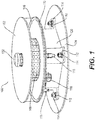
- Figure 1 shows a beacon light constructed in accordance with the principles of the invention
- Figure 2 shows the beacon light of Figure 1 in an open position
- Figure 3 shows a base of the beacon light of Figure 1 .
- Figure 1 shows optics for the beacon light that are configured to capture and direct light from multiple light emitting diode sources into a 360° horizontal beam pattern and further configured to capture and direct light from the multiple light emitting diode sources into a predetermined vertical beam pattern.
- the optics provide a substantially even light distribution over the 360° horizontal beam pattern and substantially even light distribution over the predetermined vertical beam pattern.
- the predetermined vertical beam pattern may be configured to direct light along an optical axis with a beam spread of less than 20° in a direction perpendicular to the central light-emitting axis of each one of the plurality of LEDs.
- the predetermined vertical beam pattern may be 10°.
- the predetermined vertical beam pattern may be less than 6°.
- the predetermined vertical beam pattern may be 3°.
- the optics are configured to provide very little stray or wasted light outside of this predetermined vertical beam pattern.
- other horizontal and vertical beam patterns are contemplated by the invention.
- other types of light sources other than light emitting diode are further contemplated.
- the horizontal beam pattern may be configured to provide less than 360° if desired in the particular application. For example, if multiple lights are utilized, then less than 360° of horizontal beam may be desired or appropriate.
- Figure 1 shows the beacon light 100 having a top plate 102 that may be constructed of a metallic or other material to provide weather resistance or protection from the environment to the internal components of the light 100.
- the top plate 102 may provide heat dissipation generated by the internal components.
- a bottom plate 110 may also be constructed of a metallic or other material and provide weather resistance or protection from the environment to the internal components of the light 100 as well.
- a lens 106 Arranged between the top plate 102 and the bottom plate 110 is a lens 106 providing the above-noted optic functionality. The optic functionality is described in greater detail below.
- a core 108 that includes a plurality of light emitting diodes.
- the bottom plate 110 may be arranged on a base 120.
- the base 120 may include various electrical connections to the light 100.
- a space 208 shown in Figure 2 ) to allow installers or maintenance personnel to connect, test, repair, and so on electrical and data lines connected to the light 100. This space 208 providing weather and environmental protection to these lines and their associated connections (not shown).
- the base 120 may be attached to a tower, tall building, or like structure 124. In order to provide the attachment to such a structure 124, the base 120 may include mounting structure either inside the base 120 or external to the base 120.
- the base 120 may include mounts 112. As shown in Figure 1 , there may be four mounts 112 (only three mounts are shown). Of course any number of mounts 112 are contemplated in fastening the base 120 to a structure 124.
- the mounts 112 may be tabs extending from the base 120.
- the mounts 112 may include an aspect to allow for a mechanical fastener to secure the light 100 to the structure 124.
- the base 120 may be formed of metallic or other material. In a particular aspect, the base 120 may be cast metal material.
- the mounts 112 may be formed in the casting process of the base 120. Of course other constructions are contemplated as well.
- the mounts 112 may include a hole to receive a mechanical fastener 114. Other types of mechanical fastening of the base 120 to a structure 124 are contemplated as well.
- the base may further include a strain relief 116.
- the strain relief 116 may be configured to receive the electrical and/or data lines or a conduit containing the same.
- the construction of the strain relief 116 may be to limit intrusion of water or other environmental contaminants to the light 100, conduit, or the like.
- the base 120 may further include fasteners 118 to connect and hold the bottom plate 110 to the base 120.
- the fasteners 118 may take the form of a type of mechanical fastener.
- the fasteners 118 may be spring-loaded pivotal fasteners arranged on the base 120 and that associate with a hook arranged on the bottom plate 110 as described in greater detail with respect to Figure 9 below.
- the light 100 may further include an ambient light sensor 122.
- the ambient light sensor 122 may sense the ambient light and control operation of the light 100 based on the same.
- the light 100 may include a pivot 202 connected between the bottom plate 110 and the base 120.
- the pivot 202 may be a hinge or similar structure.
- the pivot 202 may allow the top plate 102, core 108, bottom plate 110, lens 106, and the like to rotate up and away from the base 120 to allow an installer or maintenance personnel to gain access to the space 208 for installation and repair purposes.
- the fasteners 118 may hold the top plate 102, core 108, bottom plate 110, lens 106, and the like to the base 120.
- Figure 4 shows an exploded view of the beacon light of Figure 1 .
- Figure 4 shows the details of the lens 106.
- the vertical height and diameter of the lens 106 are minimized while maintaining the optical requirements of a 360° horizontal beam pattern and a 3° vertical beam pattern.
- the lens 106 may include two circular ring shaped lenses 406, 408.
- An inner lens 408 (primary) is placed very close to a horizontal polar array of light emitting diodes that are mounted on the core 108.
- a larger diameter outer lens 406 may be placed in the horizontal plane of the light emitting diodes and inner lens 408.
- Figure 4 further shows a gasket 402 arranged between the top plate 102 and an outer lens 406.
- the gasket 402 sealing a connection between the top plate 102 and the outer lens 406 and protecting the internal components of the light 100 from the environment.
- a gasket 422 is arranged between the bottom plate 110 and the outer lens 406 for the same purpose.
- Figure 4 further shows the core 108 that may be arranged on the top plate 102.
- a printed circuit board mother board 410 and a printed circuit board core board 420 Arranged within the core 108 may be a printed circuit board mother board 410 and a printed circuit board core board 420. Both the mother board 410 and the core board 420 receiving power and/or data to drive the light emitting diodes associated with the core 108.
- the data and/or power lines may be received through, for example, the strain relief 116 shown in Figure 1 .
- the data and/or power lines may extend through the space 208 shown in Figure 2 , and may extend up through a cover 204 through a cord connector 424. Subsequently, data and/or power lines may connect to the mother board 410 and/or the core board 420.
- Figure 5 shows a perspective view of a portion of the inner lens of the beacon light of Figure 1 ; and Figure 6 shows a side view of a portion of the inner lens of the beacon light of Figure 1 .
- the inner lens or primary lens 408 may be constructed from a synthetic material.
- the primary lens 408 may be molded and/or machined with the desired profile.
- the primary lens 408 may be constructed in one or more parts in order to make manufacturing easier and less costly. After the multiple parts are manufactured, they may be combined to form the ring shape shown in Figure 4 .
- the primary lens 408 may be designed to capture as much light as reasonable from the light emitting diodes over the emitted light angle. This may be accomplished, at least in part, by placing the lens close to the light emitting diode array on the core 108 and using a series of total internal reflection (TIR) steps 804 arranged on the inner surface of the primary lens 408.
- TIR total internal reflection
- a concave profile 806 on the outer surface of the primary lens 408 then redirects the collimated light in a diverging beam pattern to the secondary lens 406.
- the two lens system uses beam expander theory to provide a tight collimation necessary for the vertical beam pattern.
- the beam expander lens system takes a collimated beam, expands the beam through a diverging lens, then recollimates the beam with the secondary lens 406. The resulting beam divergence is reduced by the inverse of the magnification factor.
- Figure 7 shows a perspective view of a portion of the outer lens of the beacon light of Figure 1 .
- the outer or secondary lens 406 may be constructed using a synthetic material.
- the outer or secondary lens 406 may be molded and/or machined to form the final shape.
- the outer or secondary lens 406 may take the expanded light from the primary lens 408 and recollimate the beam pattern using a single surface Fresnel lens 802.
- the magnification factor for the lens system may be approximately 2.5. Other magnification factors are contemplated as well. This results in a reduction in beam divergence, thus a highly collimated light output.
- Figure 8 shows a core of the beacon light of Figure 1 .
- Figure 8 shows the core 108 having a plurality of printed circuit boards that have light emitting diode boards 506.
- the invention may be implemented with a single light emitting diode board 506.
- the invention may be implemented with a single flexible light emitting diode board 506.
- Each of the light emitting diode boards 506 may have at least one light emitting diode 510.
- each of the light emitting diode boards 506 may have at least one white light emitting diode 510 and one red light emitting diode 510.
- the white light emitting diode 510 being operated during certain hours of the day; and the red light emitting diode 510 being operated during certain other hours of the day.
- the beacon light may operate with only white light emitting diodes 510; or the beacon light may operate with only red light emitting diodes 510.
- the beacon light may operate with one or more infrared light emitting diodes 510 to allow for visibility utilizing night vision goggles.
- Each of the light emitting diode boards 506 may be arranged and attached to a heat sink 508 of the core 108.
- the heat sink 508 may be a cylindrical metallic construction. The metallic construction providing greater heat sinking and transferring capabilities.
- Each board may be connected to the heat sink 508 by an adhesive and/or by a mechanical fastener.
- a standoff 504 may be used to mechanically fasten one or more of the light emitting diode boards 506 to the heat sink 508.
- Each of the boards 506 may be wired and/or connected to, and receive power from, at least one of the mother board 410, the core board 420, or an adjacent LED board 506.
- the core 108 may include one or more core clips 502 that are configured with a fastener to fasten the core 108 through the core clip 502 to the top plate 102. In a particular aspect, there may be four core clips 502.
- Figure 9 shows a fastener of the beacon light of Figure 1 .
- Figure 9 shows the bottom plate arranged on top of the base 120. Between the bottom plate 110 and the base 120 may be a gasket 614 to prevent the intrusion of water and other environmental contaminants.
- Attached to the bottom of the bottom plate 110 may be a hook 602.
- the hook 602 may be fastened to the bottom of bottom plate 110 by any known manner. In the implementation shown in Figure 9 , the hook 602 is fastened to the bottom of bottom plate 110 by mechanical fastener 616.
- the fasteners 118 may include a clasp 604 to engage and hold onto the hook 602. It is noted, that in the arrangement of Figure 9 , the clasp 604 is not connected to the hook 602.
- the clasp 604 may be pivotally connected to the rotating body 606.
- the rotating body 606 rotating about a pivot point 612.
- the rotating body 606 may be connected through the pivot point 612 to a base 610.
- the base 610 may be attached to the base 120. In the implementation shown in Figure 9 , the base 610 is mechanically fastened to the base 120 by a mechanical fastener 608.
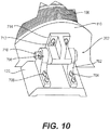
- Figure 10 shows pivot hardware of the beacon light of Figure 1 .
- Figure 10 shows a particular implementation of the pivot 202.
- the pivot 202 may include a pivot stationary portion 702.
- the pivot stationary portion 702 may be fastened to the base 120.
- the pivot stationary portion 702 may be attached to the base 120 with mechanical fasteners 704, 706.
- the pivot 202 may further include a pivot rotating portion 714.
- the pivot rotating portion 714 may be attached to the bottom plate 110.
- the pivot rotating portion 714 may be attached to the bottom plate 110 with mechanical fasteners 712.
- the pivot stationary portion 702 may be connected to the pivot rotating portion 714 with a pin 710.
- the pin 710 may extend through at least one hole formed in the pivot stationary portion 702 and at least one hole formed in the pivot rotating portion 714.
- the combination of the pin 710, the pivot rotating portion 714, and the pivot stationary portion 702 allowing the bottom plate 110 to rotate with respect to the base 120.
- the pin 710 may in some aspects include a hole arranged on the end thereof to receive a locking pin 708.
- the locking pin 708 may be configured to prevent the pin 710 from becoming dislocated and allowing the pivot rotating portion 714 to become disassociated with the pivot stationary portion 702.
- the pivot rotating portion 714 may be configured to act as a stop to limit rotation of the bottom plate 110 so as to prevent the bottom plate 110 from rotating and potentially damaging the beacon light 100.
- the pivot 202 arrangement shown in Figure 10 may allow an installer or maintenance personnel additional freedom with respect to the installation and maintenance of the beacon light 100.
- an installer may install the base 120 and subsequently attach and install the remainder of the beacon light 100 attached to the bottom plate 110.
- maintenance personnel can more easily remove the upper portion of the beacon light 100 attached to the bottom plate 110 for replacement or repair. This is due to the ease at which the pivot 202 may be taken apart due to the use of the pin 710 that can be easily removed from the pivot 202 and allow separation of the components.
- the beacon light constructed in accordance with the principles of the invention includes optics for the beacon light that are configured to capture and direct light from multiple light emitting diode sources into a 360° horizontal beam pattern and further configured to capture and direct light from the multiple light emitting diode sources into approximately 3° vertical beam pattern.
- the optics provide a substantially even light distribution over the 360° horizontal beam pattern and substantially even light distribution over the 3° vertical beam pattern.
Landscapes
- Engineering & Computer Science (AREA)
- General Engineering & Computer Science (AREA)
- Non-Portable Lighting Devices Or Systems Thereof (AREA)
Description
- This application claims the benefit from
U.S. Provisional Application No. 61/670,786 filed on July 12, 2012 U.S. Provisional Application No. 61/691,968 filed on August 22, 2012 - This disclosure is directed to a device for directing light from light emitting diode sources, and, more particularly to a device for capturing and directing light from light emitting diode sources for Beacon lights.
- Many Beacon lights or obstruction lights are constructed utilizing incandescent bulbs. The incandescent bulb provides an even light distribution. However, because Beacon lights must flash intermittently and are typically very bright, the incandescent bulbs have a tendency to have a shorter life. This is problematic when the beacon light is arranged at the top of a tall building or tower. Accordingly, maintenance personnel must climb to the top of the tower or building in order to replace the incandescent bulb.
- Other Beacon lights have been constructed using light emitting diodes. Light emitting diodes lights are beneficial in that they have a much longer life and do not typically need to be replaced as often as incandescent bulbs. However, the point source nature of light emitting diodes results in a light distribution which is overly bright or overly dim depending on the position in which the light is observed. More specifically, the beacon light must typically provide light across an essentially 360° range horizontally around the light. Similarly, the beacon light must provide a vertical spread of light having about a 3° distribution. These requirements allow the beacon light to provide the obstruction warning they are designed for such as aircraft coming from any direction and flying at an altitude close to the beacon light itself. The prior art approaches have used mirrors to spread and distribute the light. However, the mirrors or other distribution approaches do not provide an even light distribution over the desired range.
US 2011/0107587 discloses a beacon light and lens system according to the preamble of claim 1. -
DE 42 06 056 discloses a double lens system for a beacon light, in which a first, inner lens provides a diverging light beam, which is then collimated by a second, outer lens. - Additional features, advantages, and embodiments of the disclosure may be set forth or apparent from consideration of the following detailed description, drawings, and claims. Moreover, it is to be understood that both the foregoing summary of the disclosure and the following detailed description are exemplary and intended to provide further explanation without limiting the scope of the disclosure as claimed.
- The accompanying drawings, which are included to provide a further understanding of the disclosure, are incorporated in and constitute a part of this specification, illustrate embodiments of the disclosure and together with the detailed description serve to explain the principles of the disclosure. No attempt is made to show structural details of the disclosure in more detail than may be necessary for a fundamental understanding of the disclosure and the various ways in which it may be practiced. In the drawings:
-
Figure 1 shows a beacon light constructed in accordance with the principles of the invention. -
Figure 2 shows the beacon light ofFigure 1 in an open position. -
Figure 3 shows a base of the beacon light ofFigure 1 . -
Figure 4 shows an exploded view of the beacon light ofFigure 1 . -
Figure 5 shows a perspective view of a portion of the inner lens of the beacon light ofFigure 1 . -
Figure 6 shows a side view of a portion of the inner lens of the beacon light ofFigure 1 . -
Figure 7 shows a cross-section of the outer lens of the beacon light ofFigure 1 . -
Figure 8 shows a core of the beacon light ofFigure 1 . -
Figure 9 shows a fastener of the beacon light ofFigure 1 . -
Figure 10 shows pivot hardware of the beacon light ofFigure 1 . - The embodiments of the disclosure and the various features and advantageous details thereof are explained more fully with reference to the nonlimiting embodiments and examples that are described and/or illustrated in the accompanying drawings and detailed in the following description. It should be noted that the features illustrated in the drawings are not necessarily drawn to scale, and features of one embodiment may be employed with other embodiments as the skilled artisan would recognize, even if not explicitly stated herein. Descriptions of well-known components and processing techniques may be omitted so as to not unnecessarily obscure the embodiments of the disclosure. The examples used herein are intended merely to facilitate an understanding of ways in which the disclosure may be practiced and to further enable those of skill in the art to practice the embodiments of the disclosure. Accordingly, the examples and embodiments herein should not be construed as limiting the scope of the disclosure, which is defined solely by the appended claims and applicable law. Moreover, it is noted that like reference numerals represent similar parts throughout the several views of the drawings.
-
Figure 1 shows a beacon light constructed in accordance with the principles of the invention;Figure 2 shows the beacon light ofFigure 1 in an open position; andFigure 3 shows a base of the beacon light ofFigure 1 . In particular,Figure 1 shows optics for the beacon light that are configured to capture and direct light from multiple light emitting diode sources into a 360° horizontal beam pattern and further configured to capture and direct light from the multiple light emitting diode sources into a predetermined vertical beam pattern. The optics provide a substantially even light distribution over the 360° horizontal beam pattern and substantially even light distribution over the predetermined vertical beam pattern. The predetermined vertical beam pattern may be configured to direct light along an optical axis with a beam spread of less than 20° in a direction perpendicular to the central light-emitting axis of each one of the plurality of LEDs. In a particular aspect, the predetermined vertical beam pattern may be 10°. In a further particular aspect, the predetermined vertical beam pattern may be less than 6°. In yet a further aspect, the predetermined vertical beam pattern may be 3°. Moreover, the optics are configured to provide very little stray or wasted light outside of this predetermined vertical beam pattern. Of course other horizontal and vertical beam patterns are contemplated by the invention. Moreover, other types of light sources other than light emitting diode are further contemplated. Finally, the horizontal beam pattern may be configured to provide less than 360° if desired in the particular application. For example, if multiple lights are utilized, then less than 360° of horizontal beam may be desired or appropriate. - In particular,
Figure 1 shows thebeacon light 100 having atop plate 102 that may be constructed of a metallic or other material to provide weather resistance or protection from the environment to the internal components of thelight 100. Thetop plate 102 may provide heat dissipation generated by the internal components. Abottom plate 110 may also be constructed of a metallic or other material and provide weather resistance or protection from the environment to the internal components of thelight 100 as well. Arranged between thetop plate 102 and thebottom plate 110 is alens 106 providing the above-noted optic functionality. The optic functionality is described in greater detail below. Further, between thetop plate 102 and thebottom plate 110 is acore 108 that includes a plurality of light emitting diodes. - The
bottom plate 110 may be arranged on abase 120. The base 120 may include various electrical connections to the light 100. In particular, within thebase 120 may be located a space 208 (shown inFigure 2 ) to allow installers or maintenance personnel to connect, test, repair, and so on electrical and data lines connected to the light 100. Thisspace 208 providing weather and environmental protection to these lines and their associated connections (not shown). The base 120 may be attached to a tower, tall building, or likestructure 124. In order to provide the attachment to such astructure 124, thebase 120 may include mounting structure either inside the base 120 or external to thebase 120. - In one aspect, the
base 120 may include mounts 112. As shown inFigure 1 , there may be four mounts 112 (only three mounts are shown). Of course any number ofmounts 112 are contemplated in fastening the base 120 to astructure 124. Themounts 112 may be tabs extending from thebase 120. Themounts 112 may include an aspect to allow for a mechanical fastener to secure the light 100 to thestructure 124. The base 120 may be formed of metallic or other material. In a particular aspect, thebase 120 may be cast metal material. Themounts 112 may be formed in the casting process of thebase 120. Of course other constructions are contemplated as well. In a particular aspect, themounts 112 may include a hole to receive amechanical fastener 114. Other types of mechanical fastening of the base 120 to astructure 124 are contemplated as well. - The base may further include a
strain relief 116. Thestrain relief 116 may be configured to receive the electrical and/or data lines or a conduit containing the same. The construction of thestrain relief 116 may be to limit intrusion of water or other environmental contaminants to the light 100, conduit, or the like. - The base 120 may further include
fasteners 118 to connect and hold thebottom plate 110 to thebase 120. Thefasteners 118 may take the form of a type of mechanical fastener. In the implementation shown inFigure 1 , thefasteners 118 may be spring-loaded pivotal fasteners arranged on thebase 120 and that associate with a hook arranged on thebottom plate 110 as described in greater detail with respect toFigure 9 below. - The light 100 may further include an ambient
light sensor 122. The ambientlight sensor 122 may sense the ambient light and control operation of the light 100 based on the same. - As shown in
Figure 2 , the light 100 may include apivot 202 connected between thebottom plate 110 and thebase 120. Thepivot 202 may be a hinge or similar structure. Thepivot 202 may allow thetop plate 102,core 108,bottom plate 110,lens 106, and the like to rotate up and away from the base 120 to allow an installer or maintenance personnel to gain access to thespace 208 for installation and repair purposes. Thefasteners 118, not shown inFigure 2 , may hold thetop plate 102,core 108,bottom plate 110,lens 106, and the like to thebase 120. -
Figure 4 shows an exploded view of the beacon light ofFigure 1 . In particular,Figure 4 shows the details of thelens 106. The vertical height and diameter of thelens 106 are minimized while maintaining the optical requirements of a 360° horizontal beam pattern and a 3° vertical beam pattern. Thelens 106 may include two circular ring shapedlenses core 108. A larger diameter outer lens 406 (secondary) may be placed in the horizontal plane of the light emitting diodes andinner lens 408. -
Figure 4 further shows agasket 402 arranged between thetop plate 102 and anouter lens 406. Thegasket 402 sealing a connection between thetop plate 102 and theouter lens 406 and protecting the internal components of the light 100 from the environment. Similarly, agasket 422 is arranged between thebottom plate 110 and theouter lens 406 for the same purpose. -
Figure 4 further shows thecore 108 that may be arranged on thetop plate 102. Arranged within thecore 108 may be a printed circuitboard mother board 410 and a printed circuitboard core board 420. Both themother board 410 and thecore board 420 receiving power and/or data to drive the light emitting diodes associated with thecore 108. The data and/or power lines may be received through, for example, thestrain relief 116 shown inFigure 1 . The data and/or power lines may extend through thespace 208 shown inFigure 2 , and may extend up through acover 204 through acord connector 424. Subsequently, data and/or power lines may connect to themother board 410 and/or thecore board 420. -
Figure 5 shows a perspective view of a portion of the inner lens of the beacon light ofFigure 1 ; andFigure 6 shows a side view of a portion of the inner lens of the beacon light ofFigure 1 . The inner lens orprimary lens 408 may be constructed from a synthetic material. In particular, theprimary lens 408 may be molded and/or machined with the desired profile. Moreover, theprimary lens 408 may be constructed in one or more parts in order to make manufacturing easier and less costly. After the multiple parts are manufactured, they may be combined to form the ring shape shown inFigure 4 . - The
primary lens 408 may be designed to capture as much light as reasonable from the light emitting diodes over the emitted light angle. This may be accomplished, at least in part, by placing the lens close to the light emitting diode array on thecore 108 and using a series of total internal reflection (TIR) steps 804 arranged on the inner surface of theprimary lens 408. The second function of the TIR steps is to provide the first stage of collimation of the light from the light emitting diode sources. - A
concave profile 806 on the outer surface of theprimary lens 408 then redirects the collimated light in a diverging beam pattern to thesecondary lens 406. The two lens system uses beam expander theory to provide a tight collimation necessary for the vertical beam pattern. The beam expander lens system takes a collimated beam, expands the beam through a diverging lens, then recollimates the beam with thesecondary lens 406. The resulting beam divergence is reduced by the inverse of the magnification factor. -
Figure 7 shows a perspective view of a portion of the outer lens of the beacon light ofFigure 1 . The outer orsecondary lens 406 may be constructed using a synthetic material. The outer orsecondary lens 406 may be molded and/or machined to form the final shape. The outer orsecondary lens 406 may take the expanded light from theprimary lens 408 and recollimate the beam pattern using a singlesurface Fresnel lens 802. The magnification factor for the lens system may be approximately 2.5. Other magnification factors are contemplated as well. This results in a reduction in beam divergence, thus a highly collimated light output. -
Figure 8 shows a core of the beacon light ofFigure 1 . In particular,Figure 8 shows thecore 108 having a plurality of printed circuit boards that have light emittingdiode boards 506. In the implementation shown inFigure 8 , there are 36 light emittingdiode boards 506. Of course, any number of boards is contemplated by the invention. In particular, the invention may be implemented with a single light emittingdiode board 506. Moreover, the invention may be implemented with a single flexible light emittingdiode board 506. Each of the light emittingdiode boards 506 may have at least onelight emitting diode 510. In a particular implementation, each of the light emittingdiode boards 506 may have at least one whitelight emitting diode 510 and one redlight emitting diode 510. The whitelight emitting diode 510 being operated during certain hours of the day; and the redlight emitting diode 510 being operated during certain other hours of the day. Alternatively, the beacon light may operate with only whitelight emitting diodes 510; or the beacon light may operate with only redlight emitting diodes 510. Additionally, the beacon light may operate with one or more infraredlight emitting diodes 510 to allow for visibility utilizing night vision goggles. - Each of the light emitting
diode boards 506 may be arranged and attached to aheat sink 508 of thecore 108. Theheat sink 508 may be a cylindrical metallic construction. The metallic construction providing greater heat sinking and transferring capabilities. Each board may be connected to theheat sink 508 by an adhesive and/or by a mechanical fastener. As shown inFigure 8 , astandoff 504 may be used to mechanically fasten one or more of the light emittingdiode boards 506 to theheat sink 508. Each of theboards 506 may be wired and/or connected to, and receive power from, at least one of themother board 410, thecore board 420, or anadjacent LED board 506. Additionally, thecore 108 may include one or more core clips 502 that are configured with a fastener to fasten thecore 108 through thecore clip 502 to thetop plate 102. In a particular aspect, there may be four core clips 502. -
Figure 9 shows a fastener of the beacon light ofFigure 1 . In particular,Figure 9 shows the bottom plate arranged on top of thebase 120. Between thebottom plate 110 and the base 120 may be agasket 614 to prevent the intrusion of water and other environmental contaminants. Attached to the bottom of thebottom plate 110 may be ahook 602. Thehook 602 may be fastened to the bottom ofbottom plate 110 by any known manner. In the implementation shown inFigure 9 , thehook 602 is fastened to the bottom ofbottom plate 110 bymechanical fastener 616. Thefasteners 118 may include aclasp 604 to engage and hold onto thehook 602. It is noted, that in the arrangement ofFigure 9 , theclasp 604 is not connected to thehook 602. Theclasp 604 may be pivotally connected to therotating body 606. Therotating body 606 rotating about apivot point 612. When therotating body 606 rotates aboutpivot point 612 theclasp 604 moves up and down. Therotating body 606 may be connected through thepivot point 612 to abase 610. The base 610 may be attached to thebase 120. In the implementation shown inFigure 9 , thebase 610 is mechanically fastened to thebase 120 by amechanical fastener 608. -
Figure 10 shows pivot hardware of the beacon light ofFigure 1 . In particular,Figure 10 shows a particular implementation of thepivot 202. As shown inFigure 10 , thepivot 202 may include a pivotstationary portion 702. The pivotstationary portion 702 may be fastened to thebase 120. In a particular implementation, the pivotstationary portion 702 may be attached to the base 120 withmechanical fasteners pivot 202 may further include apivot rotating portion 714. Thepivot rotating portion 714 may be attached to thebottom plate 110. In a particular implementation, thepivot rotating portion 714 may be attached to thebottom plate 110 withmechanical fasteners 712. The pivotstationary portion 702 may be connected to thepivot rotating portion 714 with apin 710. Thepin 710 may extend through at least one hole formed in the pivotstationary portion 702 and at least one hole formed in thepivot rotating portion 714. The combination of thepin 710, thepivot rotating portion 714, and the pivotstationary portion 702 allowing thebottom plate 110 to rotate with respect to thebase 120. Thepin 710 may in some aspects include a hole arranged on the end thereof to receive alocking pin 708. Thelocking pin 708 may be configured to prevent thepin 710 from becoming dislocated and allowing thepivot rotating portion 714 to become disassociated with the pivotstationary portion 702. Additionally, thepivot rotating portion 714 may be configured to act as a stop to limit rotation of thebottom plate 110 so as to prevent thebottom plate 110 from rotating and potentially damaging thebeacon light 100. - The
pivot 202 arrangement shown inFigure 10 may allow an installer or maintenance personnel additional freedom with respect to the installation and maintenance of thebeacon light 100. In particular, an installer may install thebase 120 and subsequently attach and install the remainder of the beacon light 100 attached to thebottom plate 110. Similarly, maintenance personnel can more easily remove the upper portion of the beacon light 100 attached to thebottom plate 110 for replacement or repair. This is due to the ease at which thepivot 202 may be taken apart due to the use of thepin 710 that can be easily removed from thepivot 202 and allow separation of the components. - Accordingly, the beacon light constructed in accordance with the principles of the invention includes optics for the beacon light that are configured to capture and direct light from multiple light emitting diode sources into a 360° horizontal beam pattern and further configured to capture and direct light from the multiple light emitting diode sources into approximately 3° vertical beam pattern. The optics provide a substantially even light distribution over the 360° horizontal beam pattern and substantially even light distribution over the 3° vertical beam pattern.
- While the disclosure has been described in terms of exemplary embodiments, those skilled in the art will recognize that the disclosure can be practiced with modifications in the scope of the appended claims. These examples given above are merely illustrative and are not meant to be an exhaustive list of all possible designs, embodiments, applications or modifications of the disclosure.
Claims (14)
- A beacon light and lens system (100) comprising:a plurality of light emitting diodes (510);a lens comprising optics configured to capture and direct light from the plurality of light emitting diodes,the lens comprising an inner lens (408) arranged adjacent to the plurality of light emitting diodes;the lens further comprising an outer lens (406) arranged adjacent the inner lens (408); andthe outer lens (406) having a larger diameter than the inner lens (408);characterized in that the inner lens (408) collimates the light from the plurality of light emitting diodes (510), in that the inner lens (408) comprises a concave profile (806) on an outer surface thereof to redirect collimated light in a diverging beam pattern to the outer lens (406), and in that the diverging beam pattern is recollimated with the outer lens (406).
- The lens system (100) according to claim 1 wherein the inner lens (408) comprises total internal reflection steps (804) arranged on an inner surface of the inner lens (408).
- The lens system (100) according to claim 1 wherein the inner lens (408) collimates the light from the plurality of light emitting diodes and wherein the outer lens (406) is configured to recollimate and focus a diverging beam from the inner lens (408).
- The lens system (100) according to claim 1 wherein the inner lens (408) is configured to redirect collimated light in a diverging beam pattern.
- The lens system (100) according to claim 1 wherein the outer lens (406) is configured to recollimate and focus a diverging beam from the inner lens (408).
- The lens system (100) according to claim 1 wherein the outer lens (406) comprises a Fresnel lens configuration.
- The lens system (100) according to claim 1 further comprising:a top plate (102) configured to cover the lens;a bottom plate (110) configured to support the lens;a core (108) configured to hold the plurality of light emitting diodes;driving circuits for the plurality of light emitting diodes being arranged in the core (108); andthe core (108) being supported by the bottom plate (110),wherein the core (108) comprises a heat sink (508) configured to draw heat from the light emitting diodes.
- The lens system (100) according to claim 1 further comprising:a base (120) configured to be attached to a structure (124);the base (120) further configured to support a bottom plate (110); andthe base (120) further configured to receive at least one of power lines and data lines.
- The lens system (100) according to claim 1 further comprising:a pivot (202) arranged between a base (120) and a bottom plate (110) to allow the bottom plate(110) to rotate with respect to the base (120); anda fastener (712) configured to fasten the base (120) to the bottom plate (110) to prevent rotation therebetween.
- The lens system (100) according to claim 1 wherein the system generates a 360° horizontal beam pattern and vertical beam pattern less than 20°.
- The lens system (100) according to claim 1
wherein the inner lens (408) comprises total internal reflection steps (804) arranged on an inner surface of the inner lens (408), and
wherein the inner lens (408) collimates the light from the plurality of light emitting diodes and wherein the inner lens (408) is configured to redirect collimated light in a diverging beam pattern. - The lens system (100) according to claim 11 wherein the outer lens (406) is configured to recollimate and focus a diverging beam from the inner lens (408) and wherein the outer lens (406) comprises a Fresnel lens configuration.
- The lens system (100) according to claim 11 further comprising at least one of:a top plate (102) configured to cover the lens;a bottom plate (110) configured to support the lens;a core (108) configured to hold the plurality of light emitting diodes;a heat sink (508) configured to draw heat from the light emitting diodes.
- The lens system (100) according to claim 11 further comprising:a base (120) configured to be attached to a structure (124);the base (120) further configured to support a bottom plate (110);the base (120) further configured to receive at least one of power lines and data lines;a pivot (202) arranged between the base (120) and the bottom plate (110) to allow the bottom plate (110) to rotate with respect to the base (120); anda fastener (712) configured to fasten the base (120) to the bottom plate (110) to prevent rotation therebetween.
Applications Claiming Priority (3)
| Application Number | Priority Date | Filing Date | Title |
|---|---|---|---|
| US201261670786P | 2012-07-12 | 2012-07-12 | |
| US201261691968P | 2012-08-22 | 2012-08-22 | |
| PCT/US2013/050068 WO2014011873A2 (en) | 2012-07-12 | 2013-07-11 | Beacon light having a lens |
Publications (3)
| Publication Number | Publication Date |
|---|---|
| EP2872823A2 EP2872823A2 (en) | 2015-05-20 |
| EP2872823A4 EP2872823A4 (en) | 2015-12-30 |
| EP2872823B1 true EP2872823B1 (en) | 2017-11-08 |
Family
ID=49913841
Family Applications (1)
| Application Number | Title | Priority Date | Filing Date |
|---|---|---|---|
| EP13816321.7A Active EP2872823B1 (en) | 2012-07-12 | 2013-07-11 | Beacon light having a lens |
Country Status (6)
| Country | Link |
|---|---|
| US (1) | US8926148B2 (en) |
| EP (1) | EP2872823B1 (en) |
| CA (1) | CA2873980C (en) |
| DK (1) | DK2872823T3 (en) |
| ES (1) | ES2658997T3 (en) |
| WO (1) | WO2014011873A2 (en) |
Families Citing this family (12)
| Publication number | Priority date | Publication date | Assignee | Title |
|---|---|---|---|---|
| KR20140101220A (en) * | 2013-02-08 | 2014-08-19 | 삼성전자주식회사 | Lighting device |
| EP3105500A1 (en) * | 2014-01-27 | 2016-12-21 | Philips Lighting Holding B.V. | Optical device and luminaire |
| US9881466B2 (en) | 2015-10-22 | 2018-01-30 | Unimar, Inc. | Annular light system |
| US10028354B2 (en) * | 2016-02-19 | 2018-07-17 | Spx Corporation | Lighting status signaling system and method |
| KR101714972B1 (en) * | 2016-05-13 | 2017-03-09 | 한국광기술원 | Beacon module with multy multi emission angle and beacon using the same |
| US9942969B1 (en) | 2016-09-29 | 2018-04-10 | Spx Corporation | Obstructions lighting system and process having operating modes |
| US10519642B2 (en) | 2017-04-26 | 2019-12-31 | Masco Canada Limited | Adjustable sensor device for a plumbing fixture |
| IT201800005921A1 (en) * | 2018-05-31 | 2019-12-01 | LUMINOUS SIGNAL | |
| GB201812669D0 (en) * | 2018-08-03 | 2018-09-19 | Vicon Motion Systems Ltd | Active marker device and method of design thereof |
| TWI675166B (en) * | 2019-04-19 | 2019-10-21 | 嵐雅光學股份有限公司 | Lateral led light assembly |
| CN110220175A (en) * | 2019-06-06 | 2019-09-10 | 湖州明朔光电科技有限公司 | A kind of lamp radiator |
| DE102020211609A1 (en) * | 2019-10-31 | 2021-05-06 | Deere & Company | VEHICLE WARNING SIGNAL DEVICE |
Family Cites Families (119)
| Publication number | Priority date | Publication date | Assignee | Title |
|---|---|---|---|---|
| US1133536A (en) * | 1914-10-08 | 1915-03-30 | Elco Company | Side light for boats. |
| US1292123A (en) | 1916-06-17 | 1919-01-21 | Eugen Steiger | Electric device for automatically turning lights on and off. |
| US1759609A (en) * | 1928-03-03 | 1930-05-20 | American Gasaccumulator Co | Optical signal device |
| US2586374A (en) * | 1947-05-28 | 1952-02-19 | Westinghouse Electric Corp | High-intensity airport runway marker light |
| US2489076A (en) | 1948-11-12 | 1949-11-22 | Gen Electric | Photoelectric controlled luminaire |
| US2709224A (en) | 1952-10-22 | 1955-05-24 | Fisher Pierce Company Inc | Photo-electric lighting control unit |
| US2850716A (en) * | 1956-03-19 | 1958-09-02 | George W Smale | Attention arresting signal light |
| US3093785A (en) | 1959-08-31 | 1963-06-11 | Albert K Edgerton | Photoelectric signal generator |
| US3094286A (en) | 1959-09-25 | 1963-06-18 | Mc Graw Edison Co | Post top mounted lighting unit |
| US3031582A (en) | 1960-06-03 | 1962-04-24 | Sigma Instruments Inc | Mounting element for photoelectric control unit or similar article |
| US3221162A (en) | 1963-05-08 | 1965-11-30 | Elastic Stop Nut Corp | Marine lantern assembly |
| US3253139A (en) | 1963-10-31 | 1966-05-24 | Westinghouse Electric Corp | Luminaire |
| US3349239A (en) | 1965-06-21 | 1967-10-24 | Joslyn Mfg & Supply Co | Outdoor lighting luminaire |
| US3488630A (en) * | 1967-10-11 | 1970-01-06 | Flo Tronics Inc | Flasher signal or warning lamp for use on emergency vehicles and aircraft or the like |
| US3543099A (en) | 1968-04-23 | 1970-11-24 | Gen Electric | Photoelectric control device |
| US3818218A (en) * | 1971-09-30 | 1974-06-18 | Amerace Esna Corp | Lantern |
| US3875561A (en) | 1972-09-20 | 1975-04-01 | Hope Tronics Limited | Flashing vehicle warning beacon with lens and reflector |
| US3852584A (en) | 1972-12-22 | 1974-12-03 | Gte Sylvania Inc | Omnidirectional light beacon with toroidal flash lamp |
| US3961180A (en) | 1974-02-04 | 1976-06-01 | Schultz Frank H | Luminaire duration control |
| US3949211A (en) | 1974-06-21 | 1976-04-06 | Westinghouse Electric Corporation | Luminaire having ballast circuitry in photocontrol housing |
| US4023035A (en) | 1974-12-12 | 1977-05-10 | Creative Technology Corporation | Light sensitive lamp adapter |
| US4527158A (en) | 1982-07-29 | 1985-07-02 | Runnels Russell W | Aircraft collision pilot warning indicating system |
| JPS59138050A (en) * | 1983-01-27 | 1984-08-08 | トヨタ自動車株式会社 | Lamp structure |
| US4767172A (en) | 1983-01-28 | 1988-08-30 | Xerox Corporation | Collector for an LED array |
| AU560866B2 (en) | 1984-09-25 | 1987-04-16 | Matsushita Electric Works Ltd. | Passive infrared detector |
| US4791290A (en) | 1984-10-18 | 1988-12-13 | Sean Noone | Photoelectric control unit with cooling chamber |
| US4758767A (en) | 1987-05-15 | 1988-07-19 | Multipoint Control Systems, Incorporated | Self-contained analog photodiode light sensing head |
| US4839782A (en) * | 1987-12-29 | 1989-06-13 | Tomar Electronics, Inc. | Weatherproof lighting fixture with hermetically sealed base plate |
| US4907139A (en) | 1988-03-31 | 1990-03-06 | Hubbell Incorporated | Photocontrol device for grade mounted light fixture |
| DE4206056C1 (en) * | 1992-02-27 | 1993-06-17 | Pintsch Bamag Antriebs- Und Verkehrstechnik Gmbh, 4220 Dinslaken, De | Light beacon with variable output beam characteristic - determined by annular light dispersal insert fitted within main part of cylindrical lens head |
| US5450302A (en) | 1993-08-25 | 1995-09-12 | U.S. Army Corps Of Engineers As Represented By The Secretary Of The Army | Exterior high intensity discharge illumination system and method for use |
| US5899557A (en) | 1994-08-11 | 1999-05-04 | Mcdermott; Kevin | Multi-source lighting device |
| US5556189A (en) | 1995-04-05 | 1996-09-17 | Hughey & Phillips | Omni-directional airport taxiway light and fixture |
| US5806965A (en) | 1996-01-30 | 1998-09-15 | R&M Deese, Inc. | LED beacon light |
| US6183100B1 (en) | 1997-10-17 | 2001-02-06 | Truck-Lite Co., Inc. | Light emitting diode 360° warning lamp |
| US5929788A (en) | 1997-12-30 | 1999-07-27 | Star Headlight & Lantern Co. | Warning beacon |
| US6095665A (en) | 1998-04-03 | 2000-08-01 | Drake; Michael | Outdoor lamp |
| US6086220A (en) | 1998-09-30 | 2000-07-11 | Lash International Inc. | Marine safety light |
| US6278382B1 (en) | 1998-11-06 | 2001-08-21 | Demarco Ralph Anthony | Recognition/anti-collision light for aircraft |
| US20050047167A1 (en) * | 1999-08-04 | 2005-03-03 | Pederson John C. | Warning signal light bar |
| US6425678B1 (en) | 1999-08-23 | 2002-07-30 | Dialight Corporation | Led obstruction lamp |
| JP2001135102A (en) | 1999-11-05 | 2001-05-18 | Zeni Lite Buoy Co Ltd | LED lighting |
| AUPQ431399A0 (en) | 1999-11-29 | 1999-12-23 | Procter, Jeffrey Kenneth | Light emitting diode reflector |
| US8360615B2 (en) | 2000-05-08 | 2013-01-29 | Farlight, Llc | LED light module for omnidirectional luminaire |
| US7503669B2 (en) | 2000-05-08 | 2009-03-17 | Farlight, Llc | Portable luminaire |
| US6543911B1 (en) | 2000-05-08 | 2003-04-08 | Farlight Llc | Highly efficient luminaire having optical transformer providing precalculated angular intensity distribution and method therefore |
| US6483254B2 (en) | 2000-12-20 | 2002-11-19 | Honeywell International Inc. | Led strobe light |
| US6572249B2 (en) | 2001-01-18 | 2003-06-03 | Trek Bicycle Corporation | Bicycle light with LED array |
| GB0102495D0 (en) | 2001-02-01 | 2001-03-14 | Oxley Dev Co Ltd | High intensity flashing light |
| US20020122309A1 (en) | 2001-02-16 | 2002-09-05 | Abdelhafez Mohamed M. | Led beacon lamp |
| US6598998B2 (en) | 2001-05-04 | 2003-07-29 | Lumileds Lighting, U.S., Llc | Side emitting light emitting device |
| US6988815B1 (en) | 2001-05-30 | 2006-01-24 | Farlight Llc | Multiple source collimated beam luminaire |
| DE20114306U1 (en) | 2001-08-31 | 2002-01-10 | aqua signal Aktiengesellschaft Spezialleuchtenfabrik, 28307 Bremen | Lighting system especially as a hazard fire, obstacle fire or day and night markings |
| US6554441B2 (en) | 2001-08-31 | 2003-04-29 | Aqua Signal Aktiengesellschaft Spezialleuchtenfabrik | Lighting installation, in particular as a danger light, and wind rotor installation with lighting installation |
| US6525668B1 (en) | 2001-10-10 | 2003-02-25 | Twr Lighting, Inc. | LED array warning light system |
| US7123419B1 (en) * | 2001-11-21 | 2006-10-17 | Simon Jerome H | Collimating and optical elements with reduced mass |
| US6932496B2 (en) | 2002-04-16 | 2005-08-23 | Farlight Llc | LED-based elevated omnidirectional airfield light |
| US7040786B2 (en) | 2002-10-04 | 2006-05-09 | Goodrich Hella Aerospace Lighting Systems Gmbh | Anticollision light for aircraft |
| US7111961B2 (en) | 2002-11-19 | 2006-09-26 | Automatic Power, Inc. | High flux LED lighting device |
| US8662702B2 (en) * | 2009-09-08 | 2014-03-04 | Star Headlight & Lantern Co., Inc. | LED beacon |
| US7569802B1 (en) | 2003-03-20 | 2009-08-04 | Patrick Mullins | Photosensor control unit for a lighting module |
| US7016802B2 (en) | 2003-09-05 | 2006-03-21 | Tyco Electronics Corporation | Photocontrol devices having flexible mounted photosensors and methods of calibrating the same |
| US20070164875A1 (en) | 2003-11-21 | 2007-07-19 | Fredericks Thomas M | LED aircraft anticollision beacon |
| US7079041B2 (en) | 2003-11-21 | 2006-07-18 | Whelen Engineering Company, Inc. | LED aircraft anticollision beacon |
| US6991351B1 (en) | 2003-12-15 | 2006-01-31 | Twr Lighting, Inc. | Illumination system |
| US20050146875A1 (en) * | 2004-01-07 | 2005-07-07 | Tideland Signal Corporation | Side-emitting led marine signaling device |
| US6948830B1 (en) | 2004-01-14 | 2005-09-27 | Petrick John T | Dual beacon obstruction lighting system |
| US7095187B2 (en) | 2004-01-20 | 2006-08-22 | Dialight Corporation | LED strobe light |
| US7014337B2 (en) | 2004-02-02 | 2006-03-21 | Chia Yi Chen | Light device having changeable light members |
| DE202004009781U1 (en) * | 2004-06-22 | 2004-09-16 | Kolb, Klaus | An early warning lamp, with a base an optical base arrangement with a ring-shaped carrier element, inner and outer optical zone systems, and number of light emitting diodes (LED) |
| US7645053B2 (en) | 2005-01-13 | 2010-01-12 | Honeywell International Inc. | Rotationally symmetrical LED-based anti-collision light for aircraft |
| US7192155B2 (en) | 2004-08-31 | 2007-03-20 | Siemens Airfield Solutions | Airfield edge-light utilizing a side-emitting light source |
| US20060132323A1 (en) | 2004-09-27 | 2006-06-22 | Milex Technologies, Inc. | Strobe beacon |
| US20060083017A1 (en) | 2004-10-18 | 2006-04-20 | Bwt Propety, Inc. | Solid-state lighting apparatus for navigational aids |
| US7217006B2 (en) | 2004-11-20 | 2007-05-15 | Automatic Power, Inc. | Variation of power levels within an LED array |
| US20060120083A1 (en) * | 2004-12-08 | 2006-06-08 | Automatic Power, Inc. | Dual LED point-source assembly |
| DE102004063574A1 (en) | 2004-12-30 | 2006-07-13 | Osram Opto Semiconductors Gmbh | Lighting device with multiple semiconductor light sources |
| US20060176702A1 (en) | 2005-02-08 | 2006-08-10 | A L Lightech, Inc. | Warning lamp |
| US7568821B2 (en) | 2005-03-03 | 2009-08-04 | Dialight Corporation | Beacon light with reflector and light-emitting diodes |
| US7758210B2 (en) | 2005-03-03 | 2010-07-20 | Dialight Corporation | Beacon light with light-transmitting element and light-emitting diodes |
| US8591073B2 (en) | 2005-03-03 | 2013-11-26 | Dialight Corporation | Beacon light with reflector and light emitting diodes |
| US7686481B1 (en) | 2005-03-17 | 2010-03-30 | Innovative Lighting, Inc. | Illumination apparatus, method, and system for converting pseudo-collimated radiant energy into a predetermined pattern in angle space with controlled intensity |
| CN101326553B (en) | 2005-05-09 | 2011-11-30 | Bwt产权公司 | Optical signaling apparatus with precise beam control |
| JP2008541384A (en) | 2005-05-09 | 2008-11-20 | エスイーオー プレシジョン,インコーポレイティド | Omnidirectional lighting device |
| US7325739B2 (en) | 2005-05-27 | 2008-02-05 | Symbol Technologies, Inc. | Electro-optical scanner having exit window with light collecting optics |
| US7572030B2 (en) | 2005-06-22 | 2009-08-11 | Carmanah Technologies Corp. | Reflector based optical design |
| US7357530B2 (en) | 2005-07-15 | 2008-04-15 | Bwt Property, Inc. | Lighting apparatus for navigational aids |
| US7497593B2 (en) | 2005-10-07 | 2009-03-03 | Bwt Property, Inc. | Rotational obstruction and beacon signaling apparatus |
| US7731384B2 (en) | 2005-12-06 | 2010-06-08 | Dialight Corporation | Method and apparatus for providing an LED light for use in hazardous locations |
| US7722215B2 (en) | 2006-01-06 | 2010-05-25 | Barco, Inc. | 360 degree viewable light emitting apparatus |
| CA2857896C (en) | 2006-02-10 | 2017-09-12 | The Flewelling Ford Family Trust | Light emitting and receiving device |
| US7804251B2 (en) | 2006-04-10 | 2010-09-28 | Bwt Property Inc. | LED signaling apparatus with infrared emission |
| US7604380B2 (en) | 2006-06-30 | 2009-10-20 | Dialight Corporation | Apparatus for using heat pipes in controlling temperature of an LED light unit |
| DE202006017924U1 (en) | 2006-11-24 | 2008-03-27 | Patent-Treuhand-Gesellschaft für elektrische Glühlampen mbH | Lighting unit with an LED light source |
| US7619234B2 (en) | 2007-03-20 | 2009-11-17 | Syntronics L.L.C. | Ultraviolet monitoring system |
| US7641361B2 (en) | 2007-05-24 | 2010-01-05 | Brasstech, Inc. | Light emitting diode lamp |
| US7880637B2 (en) | 2007-06-11 | 2011-02-01 | Seegrid Corporation | Low-profile signal device and method for providing color-coded signals |
| US7712931B1 (en) | 2007-07-18 | 2010-05-11 | Whelen Engineering Company, Inc. | Sweep collimator |
| US8138941B2 (en) | 2007-08-17 | 2012-03-20 | Whelen Engineering Company, Inc. | LED warning light |
| US7547876B2 (en) | 2007-08-23 | 2009-06-16 | Tyco Electronics Corporation | Photocontrol devices and methods for forming the same |
| US8628219B2 (en) | 2007-09-12 | 2014-01-14 | Dialight Corporation | Compact omnidirectional LED light |
| US7794124B2 (en) | 2007-09-25 | 2010-09-14 | Michael Hulsey | Bi-directional boat running and emergency light apparatus and method |
| TW200918823A (en) | 2007-10-26 | 2009-05-01 | Foxsemicon Integrated Tech Inc | Lighting device |
| US8454212B2 (en) | 2007-12-28 | 2013-06-04 | Sirio Panel S.P.A. | Anti-collision light for aircraft |
| TW200951410A (en) | 2008-01-28 | 2009-12-16 | Koninkl Philips Electronics Nv | Lighting unit with photosensor |
| US8033683B2 (en) | 2008-02-15 | 2011-10-11 | PerkinElmer LED Solutions, Inc. | Staggered LED based high-intensity light |
| GB0804462D0 (en) | 2008-03-11 | 2008-12-17 | Bauer Eran N | Aircraft approach path indicator |
| US20100027281A1 (en) | 2008-07-31 | 2010-02-04 | Waters Stanley E | LED Anti-Collision Light for Commercial Aircraft |
| US20100091507A1 (en) | 2008-10-03 | 2010-04-15 | Opto Technology, Inc. | Directed LED Light With Reflector |
| CN101725946B (en) | 2008-10-24 | 2012-11-21 | 富准精密工业(深圳)有限公司 | Light-emitting diode lamp |
| US8287147B2 (en) | 2008-11-15 | 2012-10-16 | Rongsheng Tian | LED based omni-directional light engine |
| US8083382B1 (en) | 2008-11-24 | 2011-12-27 | Sebek Gavin D | Illumination system |
| CA2660109A1 (en) | 2009-03-25 | 2010-09-25 | Marc Henri | Warning beacon with leds |
| US8143568B2 (en) | 2009-04-02 | 2012-03-27 | Tyco Electronics Corporation | Photocontrol devices and methods for forming the same |
| DK2424779T3 (en) | 2009-05-01 | 2020-01-06 | Excelitas Tech Corp | ADVANCED LED-BASED HIGH-INTENSITY LIGHT |
| US7810968B1 (en) | 2009-05-15 | 2010-10-12 | Koninklijke Philips Electronics N.V. | LED unit for installation in a post-top luminaire |
| US20110121734A1 (en) | 2009-11-25 | 2011-05-26 | Ryan Bernard Pape | Light emitting diode (led) beacon |
| US8651695B2 (en) | 2010-03-26 | 2014-02-18 | Excelitas Technologies Corp. | LED based high-intensity light with secondary diffuser |
| US8851707B2 (en) | 2010-06-15 | 2014-10-07 | Dialight Corporation | Highly collimating reflector lens optic and light emitting diodes |
-
2013
- 2013-07-11 EP EP13816321.7A patent/EP2872823B1/en active Active
- 2013-07-11 US US13/939,687 patent/US8926148B2/en active Active
- 2013-07-11 WO PCT/US2013/050068 patent/WO2014011873A2/en not_active Ceased
- 2013-07-11 CA CA2873980A patent/CA2873980C/en active Active
- 2013-07-11 ES ES13816321.7T patent/ES2658997T3/en active Active
- 2013-07-11 DK DK13816321.7T patent/DK2872823T3/en active
Non-Patent Citations (1)
| Title |
|---|
| None * |
Also Published As
| Publication number | Publication date |
|---|---|
| EP2872823A2 (en) | 2015-05-20 |
| WO2014011873A3 (en) | 2014-03-06 |
| WO2014011873A2 (en) | 2014-01-16 |
| CA2873980C (en) | 2019-08-27 |
| US8926148B2 (en) | 2015-01-06 |
| EP2872823A4 (en) | 2015-12-30 |
| ES2658997T3 (en) | 2018-03-13 |
| US20140016320A1 (en) | 2014-01-16 |
| DK2872823T3 (en) | 2018-02-19 |
| CA2873980A1 (en) | 2014-01-16 |
Similar Documents
| Publication | Publication Date | Title |
|---|---|---|
| US8926148B2 (en) | Beacon light having a lens | |
| US8033683B2 (en) | Staggered LED based high-intensity light | |
| EP2191195B1 (en) | Compact omnidirectional led light | |
| US10532824B2 (en) | Obstruction lighting system configured to emit visible and infrared light | |
| US9010956B1 (en) | LED module with on-board reflector-baffle-trim ring | |
| EP2424779B1 (en) | Staggered led based high intensity light | |
| US8403533B1 (en) | Adjustable LED module with stationary heat sink | |
| CA2998172C (en) | Solid state lamp for retrofit | |
| US20060120083A1 (en) | Dual LED point-source assembly | |
| CA2924403A1 (en) | Beacon light having a lens | |
| US20130215611A1 (en) | Hybrid canopy lighting for optimum light beam shaping | |
| EP2707650A2 (en) | Dual zone lighting apparatus | |
| WO2011119713A1 (en) | Led based high-intensity light with secondary diffuser | |
| EP3177869B1 (en) | Led device with flexible thermal interface | |
| US20180058663A1 (en) | Light-emitting diode obstruction light | |
| EP4004440B1 (en) | Dual distribution lens for a luminaire | |
| US10634285B1 (en) | Light fixture and retrofit kit for demanding harsh environments | |
| EP2808261B1 (en) | Airfield lighting system | |
| KR101621046B1 (en) | LED marine lantern | |
| US20160320020A1 (en) | Luminaire | |
| JP2014056659A (en) | Outdoor type lighting device | |
| KR20170001691U (en) | Lighting apparatus |
Legal Events
| Date | Code | Title | Description |
|---|---|---|---|
| PUAI | Public reference made under article 153(3) epc to a published international application that has entered the european phase |
Free format text: ORIGINAL CODE: 0009012 |
|
| 17P | Request for examination filed |
Effective date: 20150209 |
|
| AK | Designated contracting states |
Kind code of ref document: A2 Designated state(s): AL AT BE BG CH CY CZ DE DK EE ES FI FR GB GR HR HU IE IS IT LI LT LU LV MC MK MT NL NO PL PT RO RS SE SI SK SM TR |
|
| AX | Request for extension of the european patent |
Extension state: BA ME |
|
| DAX | Request for extension of the european patent (deleted) | ||
| A4 | Supplementary search report drawn up and despatched |
Effective date: 20151126 |
|
| RIC1 | Information provided on ipc code assigned before grant |
Ipc: F21V 15/01 20060101ALN20151120BHEP Ipc: F21Y 103/02 20060101ALN20151120BHEP Ipc: F21V 17/20 20060101ALN20151120BHEP Ipc: F21V 5/00 20150101ALI20151120BHEP Ipc: F21V 23/04 20060101ALN20151120BHEP Ipc: F21W 111/06 20060101ALN20151120BHEP Ipc: F21V 5/04 20060101AFI20151120BHEP Ipc: F21Y 101/02 20060101ALN20151120BHEP Ipc: F21S 8/00 20060101ALN20151120BHEP Ipc: F21V 7/00 20060101ALN20151120BHEP |
|
| 17Q | First examination report despatched |
Effective date: 20160721 |
|
| RIC1 | Information provided on ipc code assigned before grant |
Ipc: F21Y 103/33 20160101ALN20170420BHEP Ipc: F21Y 115/10 20160101ALN20170420BHEP Ipc: F21V 23/04 20060101ALN20170420BHEP Ipc: F21S 8/00 20060101ALN20170420BHEP Ipc: F21V 15/01 20060101ALN20170420BHEP Ipc: F21V 5/00 20150101ALI20170420BHEP Ipc: F21W 111/06 20060101ALN20170420BHEP Ipc: F21V 7/00 20060101ALN20170420BHEP Ipc: F21V 17/20 20060101ALN20170420BHEP Ipc: F21V 5/04 20060101AFI20170420BHEP |
|
| GRAP | Despatch of communication of intention to grant a patent |
Free format text: ORIGINAL CODE: EPIDOSNIGR1 |
|
| INTG | Intention to grant announced |
Effective date: 20170601 |
|
| GRAS | Grant fee paid |
Free format text: ORIGINAL CODE: EPIDOSNIGR3 |
|
| GRAA | (expected) grant |
Free format text: ORIGINAL CODE: 0009210 |
|
| AK | Designated contracting states |
Kind code of ref document: B1 Designated state(s): AL AT BE BG CH CY CZ DE DK EE ES FI FR GB GR HR HU IE IS IT LI LT LU LV MC MK MT NL NO PL PT RO RS SE SI SK SM TR |
|
| REG | Reference to a national code |
Ref country code: GB Ref legal event code: FG4D |
|
| REG | Reference to a national code |
Ref country code: CH Ref legal event code: EP Ref country code: AT Ref legal event code: REF Ref document number: 944473 Country of ref document: AT Kind code of ref document: T Effective date: 20171115 |
|
| REG | Reference to a national code |
Ref country code: IE Ref legal event code: FG4D |
|
| REG | Reference to a national code |
Ref country code: DE Ref legal event code: R096 Ref document number: 602013029221 Country of ref document: DE |
|
| REG | Reference to a national code |
Ref country code: DK Ref legal event code: T3 Effective date: 20180213 |
|
| REG | Reference to a national code |
Ref country code: NL Ref legal event code: FP |
|
| REG | Reference to a national code |
Ref country code: SE Ref legal event code: TRGR |
|
| REG | Reference to a national code |
Ref country code: ES Ref legal event code: FG2A Ref document number: 2658997 Country of ref document: ES Kind code of ref document: T3 Effective date: 20180313 |
|
| REG | Reference to a national code |
Ref country code: LT Ref legal event code: MG4D |
|
| REG | Reference to a national code |
Ref country code: AT Ref legal event code: MK05 Ref document number: 944473 Country of ref document: AT Kind code of ref document: T Effective date: 20171108 |
|
| REG | Reference to a national code |
Ref country code: NO Ref legal event code: T2 Effective date: 20171108 |
|
| PG25 | Lapsed in a contracting state [announced via postgrant information from national office to epo] |
Ref country code: LT Free format text: LAPSE BECAUSE OF FAILURE TO SUBMIT A TRANSLATION OF THE DESCRIPTION OR TO PAY THE FEE WITHIN THE PRESCRIBED TIME-LIMIT Effective date: 20171108 |
|
| PG25 | Lapsed in a contracting state [announced via postgrant information from national office to epo] |
Ref country code: IS Free format text: LAPSE BECAUSE OF FAILURE TO SUBMIT A TRANSLATION OF THE DESCRIPTION OR TO PAY THE FEE WITHIN THE PRESCRIBED TIME-LIMIT Effective date: 20180308 Ref country code: BG Free format text: LAPSE BECAUSE OF FAILURE TO SUBMIT A TRANSLATION OF THE DESCRIPTION OR TO PAY THE FEE WITHIN THE PRESCRIBED TIME-LIMIT Effective date: 20180208 Ref country code: RS Free format text: LAPSE BECAUSE OF FAILURE TO SUBMIT A TRANSLATION OF THE DESCRIPTION OR TO PAY THE FEE WITHIN THE PRESCRIBED TIME-LIMIT Effective date: 20171108 Ref country code: GR Free format text: LAPSE BECAUSE OF FAILURE TO SUBMIT A TRANSLATION OF THE DESCRIPTION OR TO PAY THE FEE WITHIN THE PRESCRIBED TIME-LIMIT Effective date: 20180209 Ref country code: AT Free format text: LAPSE BECAUSE OF FAILURE TO SUBMIT A TRANSLATION OF THE DESCRIPTION OR TO PAY THE FEE WITHIN THE PRESCRIBED TIME-LIMIT Effective date: 20171108 Ref country code: LV Free format text: LAPSE BECAUSE OF FAILURE TO SUBMIT A TRANSLATION OF THE DESCRIPTION OR TO PAY THE FEE WITHIN THE PRESCRIBED TIME-LIMIT Effective date: 20171108 Ref country code: HR Free format text: LAPSE BECAUSE OF FAILURE TO SUBMIT A TRANSLATION OF THE DESCRIPTION OR TO PAY THE FEE WITHIN THE PRESCRIBED TIME-LIMIT Effective date: 20171108 |
|
| PG25 | Lapsed in a contracting state [announced via postgrant information from national office to epo] |
Ref country code: CY Free format text: LAPSE BECAUSE OF FAILURE TO SUBMIT A TRANSLATION OF THE DESCRIPTION OR TO PAY THE FEE WITHIN THE PRESCRIBED TIME-LIMIT Effective date: 20171108 Ref country code: EE Free format text: LAPSE BECAUSE OF FAILURE TO SUBMIT A TRANSLATION OF THE DESCRIPTION OR TO PAY THE FEE WITHIN THE PRESCRIBED TIME-LIMIT Effective date: 20171108 Ref country code: CZ Free format text: LAPSE BECAUSE OF FAILURE TO SUBMIT A TRANSLATION OF THE DESCRIPTION OR TO PAY THE FEE WITHIN THE PRESCRIBED TIME-LIMIT Effective date: 20171108 Ref country code: SK Free format text: LAPSE BECAUSE OF FAILURE TO SUBMIT A TRANSLATION OF THE DESCRIPTION OR TO PAY THE FEE WITHIN THE PRESCRIBED TIME-LIMIT Effective date: 20171108 |
|
| REG | Reference to a national code |
Ref country code: DE Ref legal event code: R097 Ref document number: 602013029221 Country of ref document: DE |
|
| REG | Reference to a national code |
Ref country code: FR Ref legal event code: PLFP Year of fee payment: 6 |
|
| PG25 | Lapsed in a contracting state [announced via postgrant information from national office to epo] |
Ref country code: PL Free format text: LAPSE BECAUSE OF FAILURE TO SUBMIT A TRANSLATION OF THE DESCRIPTION OR TO PAY THE FEE WITHIN THE PRESCRIBED TIME-LIMIT Effective date: 20171108 Ref country code: SM Free format text: LAPSE BECAUSE OF FAILURE TO SUBMIT A TRANSLATION OF THE DESCRIPTION OR TO PAY THE FEE WITHIN THE PRESCRIBED TIME-LIMIT Effective date: 20171108 Ref country code: RO Free format text: LAPSE BECAUSE OF FAILURE TO SUBMIT A TRANSLATION OF THE DESCRIPTION OR TO PAY THE FEE WITHIN THE PRESCRIBED TIME-LIMIT Effective date: 20171108 |
|
| PLBE | No opposition filed within time limit |
Free format text: ORIGINAL CODE: 0009261 |
|
| STAA | Information on the status of an ep patent application or granted ep patent |
Free format text: STATUS: NO OPPOSITION FILED WITHIN TIME LIMIT |
|
| 26N | No opposition filed |
Effective date: 20180809 |
|
| PG25 | Lapsed in a contracting state [announced via postgrant information from national office to epo] |
Ref country code: SI Free format text: LAPSE BECAUSE OF FAILURE TO SUBMIT A TRANSLATION OF THE DESCRIPTION OR TO PAY THE FEE WITHIN THE PRESCRIBED TIME-LIMIT Effective date: 20171108 |
|
| REG | Reference to a national code |
Ref country code: CH Ref legal event code: PL |
|
| PG25 | Lapsed in a contracting state [announced via postgrant information from national office to epo] |
Ref country code: LU Free format text: LAPSE BECAUSE OF NON-PAYMENT OF DUE FEES Effective date: 20180711 Ref country code: MC Free format text: LAPSE BECAUSE OF FAILURE TO SUBMIT A TRANSLATION OF THE DESCRIPTION OR TO PAY THE FEE WITHIN THE PRESCRIBED TIME-LIMIT Effective date: 20171108 |
|
| REG | Reference to a national code |
Ref country code: BE Ref legal event code: MM Effective date: 20180731 |
|
| REG | Reference to a national code |
Ref country code: IE Ref legal event code: MM4A |
|
| PG25 | Lapsed in a contracting state [announced via postgrant information from national office to epo] |
Ref country code: IE Free format text: LAPSE BECAUSE OF NON-PAYMENT OF DUE FEES Effective date: 20180711 Ref country code: CH Free format text: LAPSE BECAUSE OF NON-PAYMENT OF DUE FEES Effective date: 20180731 Ref country code: LI Free format text: LAPSE BECAUSE OF NON-PAYMENT OF DUE FEES Effective date: 20180731 |
|
| PG25 | Lapsed in a contracting state [announced via postgrant information from national office to epo] |
Ref country code: BE Free format text: LAPSE BECAUSE OF NON-PAYMENT OF DUE FEES Effective date: 20180731 |
|
| PG25 | Lapsed in a contracting state [announced via postgrant information from national office to epo] |
Ref country code: MT Free format text: LAPSE BECAUSE OF NON-PAYMENT OF DUE FEES Effective date: 20180711 |
|
| PG25 | Lapsed in a contracting state [announced via postgrant information from national office to epo] |
Ref country code: TR Free format text: LAPSE BECAUSE OF FAILURE TO SUBMIT A TRANSLATION OF THE DESCRIPTION OR TO PAY THE FEE WITHIN THE PRESCRIBED TIME-LIMIT Effective date: 20171108 |
|
| PG25 | Lapsed in a contracting state [announced via postgrant information from national office to epo] |
Ref country code: HU Free format text: LAPSE BECAUSE OF FAILURE TO SUBMIT A TRANSLATION OF THE DESCRIPTION OR TO PAY THE FEE WITHIN THE PRESCRIBED TIME-LIMIT; INVALID AB INITIO Effective date: 20130711 Ref country code: PT Free format text: LAPSE BECAUSE OF FAILURE TO SUBMIT A TRANSLATION OF THE DESCRIPTION OR TO PAY THE FEE WITHIN THE PRESCRIBED TIME-LIMIT Effective date: 20171108 |
|
| PG25 | Lapsed in a contracting state [announced via postgrant information from national office to epo] |
Ref country code: MK Free format text: LAPSE BECAUSE OF NON-PAYMENT OF DUE FEES Effective date: 20171108 |
|
| PG25 | Lapsed in a contracting state [announced via postgrant information from national office to epo] |
Ref country code: AL Free format text: LAPSE BECAUSE OF FAILURE TO SUBMIT A TRANSLATION OF THE DESCRIPTION OR TO PAY THE FEE WITHIN THE PRESCRIBED TIME-LIMIT Effective date: 20171108 |
|
| PGFP | Annual fee paid to national office [announced via postgrant information from national office to epo] |
Ref country code: NO Payment date: 20230106 Year of fee payment: 10 Ref country code: DK Payment date: 20230104 Year of fee payment: 10 |
|
| PGFP | Annual fee paid to national office [announced via postgrant information from national office to epo] |
Ref country code: SE Payment date: 20230104 Year of fee payment: 10 Ref country code: IT Payment date: 20230112 Year of fee payment: 10 |
|
| REG | Reference to a national code |
Ref country code: NO Ref legal event code: MMEP Ref country code: DK Ref legal event code: EBP Effective date: 20230731 |
|
| REG | Reference to a national code |
Ref country code: SE Ref legal event code: EUG |
|
| PG25 | Lapsed in a contracting state [announced via postgrant information from national office to epo] |
Ref country code: SE Free format text: LAPSE BECAUSE OF NON-PAYMENT OF DUE FEES Effective date: 20230712 Ref country code: NO Free format text: LAPSE BECAUSE OF NON-PAYMENT OF DUE FEES Effective date: 20230731 |
|
| PG25 | Lapsed in a contracting state [announced via postgrant information from national office to epo] |
Ref country code: DK Free format text: LAPSE BECAUSE OF NON-PAYMENT OF DUE FEES Effective date: 20230731 |
|
| PG25 | Lapsed in a contracting state [announced via postgrant information from national office to epo] |
Ref country code: IT Free format text: LAPSE BECAUSE OF NON-PAYMENT OF DUE FEES Effective date: 20230711 Ref country code: DK Free format text: LAPSE BECAUSE OF NON-PAYMENT OF DUE FEES Effective date: 20230731 |
|
| PGFP | Annual fee paid to national office [announced via postgrant information from national office to epo] |
Ref country code: NL Payment date: 20250726 Year of fee payment: 13 |
|
| PGFP | Annual fee paid to national office [announced via postgrant information from national office to epo] |
Ref country code: FI Payment date: 20250725 Year of fee payment: 13 Ref country code: ES Payment date: 20250801 Year of fee payment: 13 |
|
| PGFP | Annual fee paid to national office [announced via postgrant information from national office to epo] |
Ref country code: DE Payment date: 20250729 Year of fee payment: 13 |
|
| PGFP | Annual fee paid to national office [announced via postgrant information from national office to epo] |
Ref country code: GB Payment date: 20250728 Year of fee payment: 13 |
|
| PGFP | Annual fee paid to national office [announced via postgrant information from national office to epo] |
Ref country code: FR Payment date: 20250725 Year of fee payment: 13 |