EP2871920B1 - Fixture design for flexible LED circuit boards - Google Patents
Fixture design for flexible LED circuit boards Download PDFInfo
- Publication number
- EP2871920B1 EP2871920B1 EP14189624.1A EP14189624A EP2871920B1 EP 2871920 B1 EP2871920 B1 EP 2871920B1 EP 14189624 A EP14189624 A EP 14189624A EP 2871920 B1 EP2871920 B1 EP 2871920B1
- Authority
- EP
- European Patent Office
- Prior art keywords
- rods
- led circuit
- flexible led
- light distribution
- fixture
- Prior art date
- Legal status (The legal status is an assumption and is not a legal conclusion. Google has not performed a legal analysis and makes no representation as to the accuracy of the status listed.)
- Active
Links
Images





Classifications
-
- F—MECHANICAL ENGINEERING; LIGHTING; HEATING; WEAPONS; BLASTING
- F21—LIGHTING
- F21V—FUNCTIONAL FEATURES OR DETAILS OF LIGHTING DEVICES OR SYSTEMS THEREOF; STRUCTURAL COMBINATIONS OF LIGHTING DEVICES WITH OTHER ARTICLES, NOT OTHERWISE PROVIDED FOR
- F21V15/00—Protecting lighting devices from damage
- F21V15/01—Housings, e.g. material or assembling of housing parts
- F21V15/012—Housings with variable shape or dimensions, e.g. by means of elastically deformable materials or by movement of parts forming telescopic extensions of the housing body
-
- F—MECHANICAL ENGINEERING; LIGHTING; HEATING; WEAPONS; BLASTING
- F21—LIGHTING
- F21K—NON-ELECTRIC LIGHT SOURCES USING LUMINESCENCE; LIGHT SOURCES USING ELECTROCHEMILUMINESCENCE; LIGHT SOURCES USING CHARGES OF COMBUSTIBLE MATERIAL; LIGHT SOURCES USING SEMICONDUCTOR DEVICES AS LIGHT-GENERATING ELEMENTS; LIGHT SOURCES NOT OTHERWISE PROVIDED FOR
- F21K9/00—Light sources using semiconductor devices as light-generating elements, e.g. using light-emitting diodes [LED] or lasers
- F21K9/90—Methods of manufacture
-
- H—ELECTRICITY
- H05—ELECTRIC TECHNIQUES NOT OTHERWISE PROVIDED FOR
- H05K—PRINTED CIRCUITS; CASINGS OR CONSTRUCTIONAL DETAILS OF ELECTRIC APPARATUS; MANUFACTURE OF ASSEMBLAGES OF ELECTRICAL COMPONENTS
- H05K1/00—Printed circuits
- H05K1/18—Printed circuits structurally associated with non-printed electric components
- H05K1/189—Printed circuits structurally associated with non-printed electric components characterised by the use of flexible or folded printed circuits
-
- F—MECHANICAL ENGINEERING; LIGHTING; HEATING; WEAPONS; BLASTING
- F21—LIGHTING
- F21Y—INDEXING SCHEME ASSOCIATED WITH SUBCLASSES F21K, F21L, F21S and F21V, RELATING TO THE FORM OR THE KIND OF THE LIGHT SOURCES OR OF THE COLOUR OF THE LIGHT EMITTED
- F21Y2107/00—Light sources with three-dimensionally disposed light-generating elements
- F21Y2107/50—Light sources with three-dimensionally disposed light-generating elements on planar substrates or supports, but arranged in different planes or with differing orientation, e.g. on plate-shaped supports with steps on which light-generating elements are mounted
-
- F—MECHANICAL ENGINEERING; LIGHTING; HEATING; WEAPONS; BLASTING
- F21—LIGHTING
- F21Y—INDEXING SCHEME ASSOCIATED WITH SUBCLASSES F21K, F21L, F21S and F21V, RELATING TO THE FORM OR THE KIND OF THE LIGHT SOURCES OR OF THE COLOUR OF THE LIGHT EMITTED
- F21Y2115/00—Light-generating elements of semiconductor light sources
- F21Y2115/10—Light-emitting diodes [LED]
-
- H—ELECTRICITY
- H05—ELECTRIC TECHNIQUES NOT OTHERWISE PROVIDED FOR
- H05K—PRINTED CIRCUITS; CASINGS OR CONSTRUCTIONAL DETAILS OF ELECTRIC APPARATUS; MANUFACTURE OF ASSEMBLAGES OF ELECTRICAL COMPONENTS
- H05K2201/00—Indexing scheme relating to printed circuits covered by H05K1/00
- H05K2201/05—Flexible printed circuits [FPCs]
- H05K2201/056—Folded around rigid support or component
-
- H—ELECTRICITY
- H05—ELECTRIC TECHNIQUES NOT OTHERWISE PROVIDED FOR
- H05K—PRINTED CIRCUITS; CASINGS OR CONSTRUCTIONAL DETAILS OF ELECTRIC APPARATUS; MANUFACTURE OF ASSEMBLAGES OF ELECTRICAL COMPONENTS
- H05K2201/00—Indexing scheme relating to printed circuits covered by H05K1/00
- H05K2201/10—Details of components or other objects attached to or integrated in a printed circuit board
- H05K2201/10007—Types of components
- H05K2201/10106—Light emitting diode [LED]
-
- Y—GENERAL TAGGING OF NEW TECHNOLOGICAL DEVELOPMENTS; GENERAL TAGGING OF CROSS-SECTIONAL TECHNOLOGIES SPANNING OVER SEVERAL SECTIONS OF THE IPC; TECHNICAL SUBJECTS COVERED BY FORMER USPC CROSS-REFERENCE ART COLLECTIONS [XRACs] AND DIGESTS
- Y10—TECHNICAL SUBJECTS COVERED BY FORMER USPC
- Y10T—TECHNICAL SUBJECTS COVERED BY FORMER US CLASSIFICATION
- Y10T29/00—Metal working
- Y10T29/49—Method of mechanical manufacture
- Y10T29/49002—Electrical device making
- Y10T29/49117—Conductor or circuit manufacturing
- Y10T29/49124—On flat or curved insulated base, e.g., printed circuit, etc.
Definitions
- This disclosure relates to lighting fixtures, and more specifically to flexible LED circuit board fixtures.
- luminaires and LED arrays may be mounted using various lighting fixtures. Once the lighting fixture is assembled, the light distribution pattern it provides is typically fixed.
- US2013/044487A1 discloses a flexible substrate bearing an OLED, wherein the flexible substrate is attached to support structures that, when moved, cause the flexible substrate to change shape and to thereby change the distribution of radiant intensity emanating from the OLED.
- JP2007 115577A discloses a substrate populated with a number of LEDs, wherein the substrate is of a corrugated sheet shape with a plurality of continuous ruggednesses making up a curved shape so as to have a surface side concave.
- US2012/057347A1 provides a lighting unit comprising a substantially continuous, pliable surface and a plurality of light sources.
- the housing includes at least two side plates having hole patterns for mounting and removing the rods.
- the side plates have multiple sets of hole patterns for mounting the rods in different positions, and each position is configured to provide a unique light distribution pattern when a flexible LED circuit is woven between the rods.
- the housing includes one or more actuators operatively coupled to at least one of the rods and configured to adjust rod positioning, each position configured to provide a unique light distribution pattern when a flexible LED circuit is woven between the rods.
- the one or more actuators are operatively coupled to the rods via side plates to which the rods are secured.
- the flexible LED circuit has a reflective surface.
- the spacing of LEDs within the flexible LED circuit is determined by the light distribution pattern produced when the flexible LED circuit is woven between the rods.
- the lighting fixture is configured to provide a customized the light distribution pattern by altering the placement of the rods. In some such cases, altering the placement of the rods is accomplished via an actuator.
- the actuator is controlled by a processor programmed to automatically adjust light distribution.
- the rods are transparent. In some cases, the rods are reflective.
- the method includes fabricating the flexible LED circuit wherein the spacing of LEDs within the circuit is determined based on the desired light distribution pattern.
- the flexible LED circuit housing is configured to hold the flexible LED circuit in at least one of a concave, convex, and/or corrugated shape.
- determining the desired light distribution pattern includes receiving a desired light distribution pattern from a customer.
- the method includes adjusting rod positioning within the housing using a plurality of linear actuators operatively coupled to the rods, wherein each rod positioning pattern provides a unique light distribution pattern when a flexible LED circuit is woven between the rods.
- the flexible LED circuit boards include an array of LED packages or LED chips and the surface of the flexible circuit boards is highly reflective, in some embodiments.
- a flexible LED circuit board may be shaped to conform to a rigid preform and the preform may be concave, convex, corrugated, or have any other custom shape depending on the desired light distribution pattern.
- the shape of the preform as well as the location of the LEDs within the flexible LED circuit will determine the light distribution of the light fixture.
- the lighting fixture may have multiple rods held in place with side plates and a flexible LED circuit board may be woven between the rods, in some embodiments.
- a set of hole patterns in the side plates will determine the location of the rods and the rods will determine the shape of the flexible LED circuit.
- the side plates may include multiple hole patterns and attaching the rods to different hole patterns will result in different light distributions.
- the rods may be attached to the side plates using mechanical actuators, or other techniques that allow the rod positioning to be mechanically adjusted.
- the rods instead of removing the rods from one set of hole patterns and inserting them into another set of hole patterns, the rods may be mechanically repositioned with respect to the side plates within a range of position patterns, each pattern providing a unique light distribution. The position of the rods as well as how the flexible LED circuit is woven between the rods will determine the final shape of the LED circuit within the lighting fixture.
- Flexible substrates with screen printed circuit patterns are used to fabricate flexible circuit boards.
- flexible LED circuit boards with reflective substrates may be configured into multiple shapes and may provide various light distribution patterns with the same physical parts.
- different LED placements within a flexible circuit board may provide different light distributions even if the shape of the flexible circuit is held constant.
- a lighting fixture may be designed that takes advantage of these unique characteristics of a flexible LED circuit board.
- a lighting fixture for housing a flexible circuit board populated with an array of LED packages or LED chips.
- the flexible substrate of the LED array may be a reflective material (e.g., PET), and the circuit pattern may be screen printed onto the substrate, in some embodiments, which can reduce production cost as compared to standard circuit boards or metal substrate boards.
- the flexible board may be shaped prior to being used in a light fixture, in some cases, and the flexible board may conform to a non-flat shape, in some embodiments.
- Such a design has a low input power density such that heat may be dissipated by convection and radiation and no heat sink is required.
- a flexible LED array with a reflective surface may provide customized light delivery with a fixed set of parts.
- the same parts may be used to provide a highly directed light source or a dissipated light source depending on the contours of the flexible LED array and the spacing of the LEDs within the array.
- a flexible LED array is placed against a curved preform and the LED linear arrangements may be either separate strips with appropriate electrical connections or printed circuit patterns on a large flexible sheet.
- the curved preform may be concave, convex, corrugated, or any other custom shape depending upon the intended light distribution.
- the curved preform may be a section of PVC corrugated roofing material.
- the flexible LED array may be laced between a number of rods and the placement of the rods may customize the shape of the LED array and therefore the light distribution.
- the lighting fixture may include two side plates that hold the rods in place.
- custom screen printed circuits or LED arrays may be matched with the correct fixture configuration in order to achieve the desired light distribution.
- the variations in shape and LED placement would contribute to the final light distribution and could be customized for particular applications without major changes in parts.
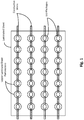
- Figure 1 shows a flexible laminated LED circuit.
- the LED circuit includes four copper ribbons and the upper laminate sheet has multiple perforations exposing portions of the copper ribbons for the placement of the LED packages.
- the upper laminate sheet in this particular embodiment is transparent and the entire copper ribbons are visible, while the lower laminate sheet has a reflective upper surface. In other embodiments, the upper laminate sheet may have a reflective upper surface.
- this particular example shows four copper ribbons laminated between two sheets, other embodiments may include fewer or more copper ribbons and the copper ribbons may be replaced with copper wires, or any other suitable conductive material.
- the thin copper ribbon may be around 0,0762 mm (.003 inches) thick.
- the LED packages may be attached using a conductive epoxy or solder, in some embodiments. Because the LED packages are being attached to a metallic conductive wire (a copper ribbon in this example), solder may be used in order to avoid the difficulties associated with conductive epoxies.
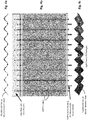
- Figures 2a-b illustrate examples of flexible LED circuit boards including multiple LED strings connected in parallel.
- a flexible LED circuit may be fabricated with screen printed Ag ink on a flexible substrate, in some embodiments.
- the substrate could be, for example, PET or any other suitable flexible substrate material.
- LED packages may be connected in series along the conductive traces to form multiple LED strings and the surface of the flexible circuit board may be reflective.
- Figure 2b illustrates the flexibility of the LED circuit board when it is rolled.
- Figure 3a shows a cross-sectional view of various LED package spacings that may provide different light distributions, according to an embodiment of the present invention.
- the flexible LED array is arranged in a corrugated shape and the top LED package spacing has the LEDs near the crest of each corrugated wave, while the middle LED package spacing has the LEDs at the center of each corrugated wave, and the lower LED package spacing has the LEDs at the bottom of each corrugated wave.
- Figure 3b shows a view from below of the flexible LED circuit fitted to a corrugated form, according to one embodiment of the present invention. The direct light path from the LED packages is shown.
- Such a corrugated shape could be readily used in various area lighting applications including, for example, a drop ceiling light fixtures with dimensions of 61 cm (2 ft.) x 61 cm (2 ft.) or 61 cm (2 ft.) x 122 cm (4 ft.)
- the lighting fixtures described herein could be designed for any area lighting application and the present invention is not intended to be limited to any particular size or set of dimensions.
- Figures 4a-c collectively illustrate an example LED lighting fixture with a flexible LED circuit woven between rods, according to an embodiment of the present invention.
- the flexible circuit board may be mounted within a lighting fixture housing without being attached to the surface of a rigid preform.
- Such a fixture may provide a more versatile system whereby the "wavelength” and the "amplitude" of the shaped flexible LED circuit would be more customizable based on the location of the rods.
- the example LED circuit board in Figures 4a-c has the LED packages placed such that they are near the crest of the circuit board wave pattern.
- the rods in this example define the shape of the flexible LED circuit when the circuit is woven between the rods.
- this design has two side plates, each having hole patterns through which the rods may be placed.
- Figure 4c shows a view from below of the flexible LED circuit, and the direct light path from the LED packages is shown. The direction of the light from the LED packages may be changed, for example, by changing the spacing and location of the rods.
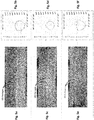
- Figures 5a-f collectively illustrate three LED package spacings along with their corresponding light distribution patterns, according to various embodiments of the present invention.
- the light distribution is influenced by locating the LED strips at different points along the "curve" or "wave" of the corrugated LED circuit (whether the circuit is attached to a corrugated preform or shaped using rods and side plates).
- Figure 5a shows the LED strips placed near the crest of the corrugated LED circuit and
- Figure 5b is a graph of the corresponding polar light distribution.
- Figure 5c shows the LED strips placed near the middle of the corrugated LED circuit shape and
- Figure 5d is a graph of the corresponding polar light distribution.
- Figure 5e shows the LED strips placed near the bottom of the corrugated LED circuit shape and figure 5f is a graph of the corresponding polar light distribution.
- the polar light distribution plots shown in Figures 5b, 5d, and 5f graph the light intensity in candelas (CD) and demonstrate that there is a significant difference in the light distribution pattern for each LED strip placement.
- CD candelas
- Figures 6a-b show graphs of the light distribution coming from two points along a sinusoidal shaped flexible LED circuit, according to two embodiments of the present invention.
- non-diffused reflection is assumed for illustrative purposes.
- the example in Figure 6a shows the light distribution coming from a point near the crest of the sinusoidal LED circuit
- the example in Figure 6b shows the light distribution coming from a point near the middle of the sinusoidal LED circuit.
- a flat array of Lambertian LED packages may produce a Lambertian light distribution when used in a downward facing lighting application, as shown in these example embodiments.
- minor changes in the LED package locations would produce different light distribution patterns other than a Lambertian distribution.
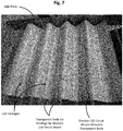
- Figure 7 shows an example flexible LED circuit including multiple LED packages woven between transparent rods, according to an embodiment of the present invention.
- the rods are glass tubes and the side plates are 6,35 mm (1 ⁇ 4 inch) aluminum plates having a particular hole-pattern.
- side plates may include multiple hole-patterns and the user may configure the rod placement as desired.
- a consumer may specify the type of light distribution desired and the rod placement may be determined and the circuit may be laced for the desired application.
- the rods could be made of reflective material and may be fastened with setscrews or held with lock nuts on the end of threaded rods, in some embodiments.
- the rods may also be replaced with cables laced through the hole pattern and held taught at the ends, in some embodiments. Such cables could be thin and coated with a reflective material.
- the rods may be attached to mechanical actuators within the side plates that allow the rod positioning to be dynamically adjusted.
- the shape of the flexible circuit board may be adjusted by mechanically repositioning the rods within a range of user selectable position patterns, each pattern providing a unique light distribution.
- electromechanical, mechanical, hydraulic, and/or any other suitable linear actuator scheme may be used to adjust rod positioning in various dimensions and the present invention is not limited to any particular type of actuator.
- Figures 8a-d illustrate various shapes and fixture designs for flexible LED circuits, according to various embodiments of the present invention.
- Figure 8a shows a flexible LED array attached to a concave down rigid preform
- Figure 8b shows a flexible LED array attached to a concave up rigid preform
- each LED circuit shape provides a specific light distribution pattern.
- Figures 8c-d show a concave down configuration for a flexible LED circuit utilizing a rod and side plate configuration.
- Figure 8c is a cross-sectional view of the rod and side plate fixture with the flexible LED circuit woven between the rods while Figure 8d shows the same configuration from below.
- the flexible LED circuit may be replaced with a new flexible LED board with the same or different pattern and the fixture itself could remain the same.
- the various preforms and rod arrangements may be incorporated within a light fixture housing, in some embodiments.
- Figure 9 illustrates a method for fabricating a light fixture for a flexible LED lighting circuit, according to an embodiment of the present invention.
- the method may begin with determining 901 the desired light distribution. Once the desired light distribution is known, the method may continue with determining 902 the ideal circuit shape and LED placement in order to achieve the desired light distribution. As discussed above, the light distribution may be manipulated by altering the shape of the flexible LED circuit as well as the placement of the LED strings within the LED circuit.
- the method may continue with determining 903 whether the flexible LED circuit will be fastened to a rigid form. In some cases, the rigid preform may be concave, convex, corrugated, or any other suitable shape for achieving the desired light distribution.
- the method may continue with fabricating 904 the flexible LED circuit and the rigid form. As discussed above, the shape of the preform as well as the placement of the LED strings within the flexible LED circuit depends on the desired light distribution. The method may then continue with assembling 906 the light fixture housing, which may include attaching the LED circuit to the rigid preform. If the flexible LED circuit is not to be attached to a rigid form, the method may continue with fabricating 905 the flexible LED circuit and light fixture side plates with the desired hole patterns or achieving the intended light distribution. As discussed above, the hole patterns in the side plates are used for inserting the rods which will determine the shape of the flexible LED circuit. The method may then continue with assembling 906 the light fixture housing, which in this particular case includes inserting transparent or reflective rods into the holes of the side plates and weaving the flexible LED circuit between the rods.
Landscapes
- Engineering & Computer Science (AREA)
- Microelectronics & Electronic Packaging (AREA)
- General Engineering & Computer Science (AREA)
- Manufacturing & Machinery (AREA)
- Physics & Mathematics (AREA)
- Optics & Photonics (AREA)
- Non-Portable Lighting Devices Or Systems Thereof (AREA)
- Fastening Of Light Sources Or Lamp Holders (AREA)
Description
- This disclosure relates to lighting fixtures, and more specifically to flexible LED circuit board fixtures.
- In lighting systems luminaires and LED arrays may be mounted using various lighting fixtures. Once the lighting fixture is assembled, the light distribution pattern it provides is typically fixed.
-
US2013/044487A1 discloses a flexible substrate bearing an OLED, wherein the flexible substrate is attached to support structures that, when moved, cause the flexible substrate to change shape and to thereby change the distribution of radiant intensity emanating from the OLED. -
JP2007 115577A -
US2012/057347A1 provides a lighting unit comprising a substantially continuous, pliable surface and a plurality of light sources. - One example embodiment of the present invention provides a lighting fixture according to claim 1. In some cases, the plurality of rods are configured to define a corrugated shape. In some cases, the housing includes at least two side plates having hole patterns for mounting and removing the rods. In some cases, the side plates have multiple sets of hole patterns for mounting the rods in different positions, and each position is configured to provide a unique light distribution pattern when a flexible LED circuit is woven between the rods. In some cases, the housing includes one or more actuators operatively coupled to at least one of the rods and configured to adjust rod positioning, each position configured to provide a unique light distribution pattern when a flexible LED circuit is woven between the rods. In some such cases, the one or more actuators are operatively coupled to the rods via side plates to which the rods are secured. In some cases, the flexible LED circuit has a reflective surface. In some cases, the spacing of LEDs within the flexible LED circuit is determined by the light distribution pattern produced when the flexible LED circuit is woven between the rods. In some cases, the lighting fixture is configured to provide a customized the light distribution pattern by altering the placement of the rods. In some such cases, altering the placement of the rods is accomplished via an actuator. In some such cases, the actuator is controlled by a processor programmed to automatically adjust light distribution. In some cases, the rods are transparent. In some cases, the rods are reflective.
- Another embodiment of the present invention provides a method of fabricating a lighting fixture according to claim 11. In some cases, the method includes fabricating the flexible LED circuit wherein the spacing of LEDs within the circuit is determined based on the desired light distribution pattern. In some cases, the flexible LED circuit housing is configured to hold the flexible LED circuit in at least one of a concave, convex, and/or corrugated shape. In some cases, determining the desired light distribution pattern includes receiving a desired light distribution pattern from a customer. In some cases, the method includes adjusting rod positioning within the housing using a plurality of linear actuators operatively coupled to the rods, wherein each rod positioning pattern provides a unique light distribution pattern when a flexible LED circuit is woven between the rods.
-
-
Figure 1 shows a flexible laminated LED circuit. -
Figures 2a-b illustrate two examples of flexible LED circuits fabricated with screen printed Ag ink on polyester including multiple LED strings connected in parallel. -
Figure 3a shows a cross-sectional view of various LED package spacings that may provide different light distributions, according to an embodiment of the present invention. -
Figure 3b shows a view from below of the flexible LED circuit fitted to a corrugated form, according to one embodiment of the present invention. -
Figures 4a-c collectively illustrate an example LED lighting fixture with a flexible LED circuit woven between rods, according to an embodiment of the present invention. -
Figures 5a-f collectively illustrate three LED package spacings along with their corresponding light distribution patterns, according to various embodiments of the present invention. -
Figures 6a-b show graphs of the light distribution coming from two points along a sinusoidal shaped flexible LED circuit, according to two embodiments of the present invention. -
Figure 7 shows an example flexible LED circuit including multiple LED packages woven between transparent rods, according to an embodiment of the present invention. -
Figures 8a-d illustrate various shapes and fixture designs for flexible LED circuits, according to various embodiments of the present invention. -
Figure 9 illustrates a method for fabricating a light fixture for a flexible LED lighting circuit, according to an embodiment of the present invention. - Techniques are disclosed for designing light fixtures for flexible LED circuit boards. The flexible LED circuit boards include an array of LED packages or LED chips and the surface of the flexible circuit boards is highly reflective, in some embodiments. In one example, a flexible LED circuit board may be shaped to conform to a rigid preform and the preform may be concave, convex, corrugated, or have any other custom shape depending on the desired light distribution pattern. In such an example, the shape of the preform as well as the location of the LEDs within the flexible LED circuit will determine the light distribution of the light fixture. Alternatively, the lighting fixture may have multiple rods held in place with side plates and a flexible LED circuit board may be woven between the rods, in some embodiments. In such embodiments, a set of hole patterns in the side plates will determine the location of the rods and the rods will determine the shape of the flexible LED circuit. In some cases, the side plates may include multiple hole patterns and attaching the rods to different hole patterns will result in different light distributions. In other embodiments, the rods may be attached to the side plates using mechanical actuators, or other techniques that allow the rod positioning to be mechanically adjusted. In such embodiments, instead of removing the rods from one set of hole patterns and inserting them into another set of hole patterns, the rods may be mechanically repositioned with respect to the side plates within a range of position patterns, each pattern providing a unique light distribution. The position of the rods as well as how the flexible LED circuit is woven between the rods will determine the final shape of the LED circuit within the lighting fixture.
- Flexible substrates with screen printed circuit patterns are used to fabricate flexible circuit boards. However, flexible LED circuit boards with reflective substrates may be configured into multiple shapes and may provide various light distribution patterns with the same physical parts. Furthermore, different LED placements within a flexible circuit board may provide different light distributions even if the shape of the flexible circuit is held constant. A lighting fixture may be designed that takes advantage of these unique characteristics of a flexible LED circuit board.
- Thus, in accordance with an embodiment of the present invention, a lighting fixture is disclosed for housing a flexible circuit board populated with an array of LED packages or LED chips. The flexible substrate of the LED array may be a reflective material (e.g., PET), and the circuit pattern may be screen printed onto the substrate, in some embodiments, which can reduce production cost as compared to standard circuit boards or metal substrate boards. The flexible board may be shaped prior to being used in a light fixture, in some cases, and the flexible board may conform to a non-flat shape, in some embodiments. Such a design has a low input power density such that heat may be dissipated by convection and radiation and no heat sink is required. In one embodiment, a flexible LED array with a reflective surface may provide customized light delivery with a fixed set of parts. For example, the same parts may be used to provide a highly directed light source or a dissipated light source depending on the contours of the flexible LED array and the spacing of the LEDs within the array.
- In one example embodiment, a flexible LED array is placed against a curved preform and the LED linear arrangements may be either separate strips with appropriate electrical connections or printed circuit patterns on a large flexible sheet. The curved preform may be concave, convex, corrugated, or any other custom shape depending upon the intended light distribution. In some cases, the curved preform may be a section of PVC corrugated roofing material. In another embodiment, the flexible LED array may be laced between a number of rods and the placement of the rods may customize the shape of the LED array and therefore the light distribution. In one such example, the lighting fixture may include two side plates that hold the rods in place.
- In some embodiments, custom screen printed circuits or LED arrays may be matched with the correct fixture configuration in order to achieve the desired light distribution. The variations in shape and LED placement would contribute to the final light distribution and could be customized for particular applications without major changes in parts.
-
Figure 1 shows a flexible laminated LED circuit. As can be seen, the LED circuit includes four copper ribbons and the upper laminate sheet has multiple perforations exposing portions of the copper ribbons for the placement of the LED packages. The upper laminate sheet in this particular embodiment is transparent and the entire copper ribbons are visible, while the lower laminate sheet has a reflective upper surface. In other embodiments, the upper laminate sheet may have a reflective upper surface. Although this particular example shows four copper ribbons laminated between two sheets, other embodiments may include fewer or more copper ribbons and the copper ribbons may be replaced with copper wires, or any other suitable conductive material. In some cases, the thin copper ribbon may be around 0,0762 mm (.003 inches) thick. The LED packages may be attached using a conductive epoxy or solder, in some embodiments. Because the LED packages are being attached to a metallic conductive wire (a copper ribbon in this example), solder may be used in order to avoid the difficulties associated with conductive epoxies. -
Figures 2a-b illustrate examples of flexible LED circuit boards including multiple LED strings connected in parallel. As can be seen in the example ofFigure 2a , a flexible LED circuit may be fabricated with screen printed Ag ink on a flexible substrate, in some embodiments. The substrate could be, for example, PET or any other suitable flexible substrate material. LED packages may be connected in series along the conductive traces to form multiple LED strings and the surface of the flexible circuit board may be reflective.Figure 2b illustrates the flexibility of the LED circuit board when it is rolled. -
Figure 3a shows a cross-sectional view of various LED package spacings that may provide different light distributions, according to an embodiment of the present invention. As can be seen in this example, the flexible LED array is arranged in a corrugated shape and the top LED package spacing has the LEDs near the crest of each corrugated wave, while the middle LED package spacing has the LEDs at the center of each corrugated wave, and the lower LED package spacing has the LEDs at the bottom of each corrugated wave.Figure 3b shows a view from below of the flexible LED circuit fitted to a corrugated form, according to one embodiment of the present invention. The direct light path from the LED packages is shown. Such a corrugated shape could be readily used in various area lighting applications including, for example, a drop ceiling light fixtures with dimensions of 61 cm (2 ft.) x 61 cm (2 ft.) or 61 cm (2 ft.) x 122 cm (4 ft.) However, the lighting fixtures described herein could be designed for any area lighting application and the present invention is not intended to be limited to any particular size or set of dimensions. -
Figures 4a-c collectively illustrate an example LED lighting fixture with a flexible LED circuit woven between rods, according to an embodiment of the present invention. In such an embodiment, the flexible circuit board may be mounted within a lighting fixture housing without being attached to the surface of a rigid preform. Such a fixture may provide a more versatile system whereby the "wavelength" and the "amplitude" of the shaped flexible LED circuit would be more customizable based on the location of the rods. The example LED circuit board inFigures 4a-c has the LED packages placed such that they are near the crest of the circuit board wave pattern. As can be seen inFigure 4a , the rods in this example define the shape of the flexible LED circuit when the circuit is woven between the rods. As can be seen in the example ofFigure 4b , this design has two side plates, each having hole patterns through which the rods may be placed.Figure 4c shows a view from below of the flexible LED circuit, and the direct light path from the LED packages is shown. The direction of the light from the LED packages may be changed, for example, by changing the spacing and location of the rods. -
Figures 5a-f collectively illustrate three LED package spacings along with their corresponding light distribution patterns, according to various embodiments of the present invention. In these example embodiments, the light distribution is influenced by locating the LED strips at different points along the "curve" or "wave" of the corrugated LED circuit (whether the circuit is attached to a corrugated preform or shaped using rods and side plates).Figure 5a shows the LED strips placed near the crest of the corrugated LED circuit andFigure 5b is a graph of the corresponding polar light distribution.Figure 5c shows the LED strips placed near the middle of the corrugated LED circuit shape andFigure 5d is a graph of the corresponding polar light distribution.Figure 5e shows the LED strips placed near the bottom of the corrugated LED circuit shape andfigure 5f is a graph of the corresponding polar light distribution. The polar light distribution plots shown inFigures 5b, 5d, and 5f graph the light intensity in candelas (CD) and demonstrate that there is a significant difference in the light distribution pattern for each LED strip placement. As can be seen, therefore, the light distribution of a flexible LED circuit is customizable using the same basic parts, depending on the location of the LED strips within the shaped LED circuit. -
Figures 6a-b show graphs of the light distribution coming from two points along a sinusoidal shaped flexible LED circuit, according to two embodiments of the present invention. In these example embodiments, non-diffused reflection is assumed for illustrative purposes. The example inFigure 6a shows the light distribution coming from a point near the crest of the sinusoidal LED circuit, while the example inFigure 6b shows the light distribution coming from a point near the middle of the sinusoidal LED circuit. In one specific example embodiment, a flat array of Lambertian LED packages may produce a Lambertian light distribution when used in a downward facing lighting application, as shown in these example embodiments. As can be seen when comparing the example ofFigure 6a with the example ofFigure 6b , minor changes in the LED package locations would produce different light distribution patterns other than a Lambertian distribution. -
Figure 7 shows an example flexible LED circuit including multiple LED packages woven between transparent rods, according to an embodiment of the present invention. In this particular example embodiment, the rods are glass tubes and the side plates are 6,35 mm (¼ inch) aluminum plates having a particular hole-pattern. In other embodiments, side plates may include multiple hole-patterns and the user may configure the rod placement as desired. In still other embodiments, a consumer may specify the type of light distribution desired and the rod placement may be determined and the circuit may be laced for the desired application. The rods could be made of reflective material and may be fastened with setscrews or held with lock nuts on the end of threaded rods, in some embodiments. The rods may also be replaced with cables laced through the hole pattern and held taught at the ends, in some embodiments. Such cables could be thin and coated with a reflective material. As discussed above, in other embodiments the rods may be attached to mechanical actuators within the side plates that allow the rod positioning to be dynamically adjusted. In such embodiments, instead of removing the rods from one set of hole patterns and inserting them into another set of hole patterns, the shape of the flexible circuit board may be adjusted by mechanically repositioning the rods within a range of user selectable position patterns, each pattern providing a unique light distribution. As will be appreciated, electromechanical, mechanical, hydraulic, and/or any other suitable linear actuator scheme may be used to adjust rod positioning in various dimensions and the present invention is not limited to any particular type of actuator.
Figures 8a-d illustrate various shapes and fixture designs for flexible LED circuits, according to various embodiments of the present invention.Figure 8a shows a flexible LED array attached to a concave down rigid preform, whileFigure 8b shows a flexible LED array attached to a concave up rigid preform, and each LED circuit shape provides a specific light distribution pattern.Figures 8c-d show a concave down configuration for a flexible LED circuit utilizing a rod and side plate configuration.Figure 8c is a cross-sectional view of the rod and side plate fixture with the flexible LED circuit woven between the rods whileFigure 8d shows the same configuration from below. Various shapes and heights may be used for the rigid forms, and in some cases the flexible LED circuit may be replaced with a new flexible LED board with the same or different pattern and the fixture itself could remain the same. The various preforms and rod arrangements may be incorporated within a light fixture housing, in some embodiments. -
Figure 9 illustrates a method for fabricating a light fixture for a flexible LED lighting circuit, according to an embodiment of the present invention. The method may begin with determining 901 the desired light distribution. Once the desired light distribution is known, the method may continue with determining 902 the ideal circuit shape and LED placement in order to achieve the desired light distribution. As discussed above, the light distribution may be manipulated by altering the shape of the flexible LED circuit as well as the placement of the LED strings within the LED circuit. The method may continue with determining 903 whether the flexible LED circuit will be fastened to a rigid form. In some cases, the rigid preform may be concave, convex, corrugated, or any other suitable shape for achieving the desired light distribution. If the LED circuit will be fastened to a rigid form, the method may continue with fabricating 904 the flexible LED circuit and the rigid form. As discussed above, the shape of the preform as well as the placement of the LED strings within the flexible LED circuit depends on the desired light distribution. The method may then continue with assembling 906 the light fixture housing, which may include attaching the LED circuit to the rigid preform. If the flexible LED circuit is not to be attached to a rigid form, the method may continue with fabricating 905 the flexible LED circuit and light fixture side plates with the desired hole patterns or achieving the intended light distribution. As discussed above, the hole patterns in the side plates are used for inserting the rods which will determine the shape of the flexible LED circuit. The method may then continue with assembling 906 the light fixture housing, which in this particular case includes inserting transparent or reflective rods into the holes of the side plates and weaving the flexible LED circuit between the rods. - Numerous embodiments will be apparent, and features described herein can be combined in any number of configurations.
- The foregoing description of the embodiments of the invention has been presented for the purposes of illustration and description. It is not intended to be exhaustive or to limit the invention to the precise form disclosed. Many modifications and variations are possible in light of this disclosure. It is intended that the scope of the invention be limited not by this detailed description, but rather by the claims appended hereto.
Claims (15)
- A lighting fixture comprising:a lighting fixture housing;a flexible LED circuit woven between a plurality of rods;the plurality of rods mounted within the housing configured to define a non-flat shape for the flexible LED circuit, wherein the placement of the rods within the housing is determined by a desired light distribution pattern produced when the flexible LED circuit is woven between the rods.
- The fixture of claim 1 wherein the plurality of rods are configured to define a corrugated shape.
- The fixture of claim 1 wherein the housing comprises at least two side plates having hole patterns for mounting and removing the rods; wherein preferably the side plates have multiple sets of hole patterns for mounting the rods in different positions, each position configured to provide a unique light distribution pattern when a flexible LED circuit is woven between the rods.
- The fixture of claim 1 wherein the housing comprises one or more actuators operatively coupled to at least one of the rods and configured to adjust rod positioning, each position configured to provide a unique light distribution pattern when a flexible LED circuit is woven between the rods; wherein preferably the one or more actuators are operatively coupled to the rods via side plates to which the rods are secured.
- The fixture of claim 1 wherein the flexible LED circuit has a reflective surface.
- The fixture of claim 1 wherein the spacing of LEDs within the flexible LED circuit is determined by the light distribution pattern produced when the flexible LED circuit is woven between the rods.
- The fixture of claim 1 wherein the lighting fixture is configured to provide a customized light distribution pattern by altering the placement of the rods.
- The fixture of claim 7 wherein altering the placement of the rods is accomplished via an actuator; wherein preferably the actuator is controlled by a processor programmed to automatically adjust light distribution.
- The fixture of claim 1 wherein the rods are transparent.
- The fixture of claim 1 wherein the rods are reflective.
- A method of fabricating a lighting fixture comprising:determining a desired light distribution pattern;providing a flexible LED circuit;fabricating a flexible LED circuit housing configured to hold a flexible LED circuit in a desired non-flat shape, wherein the housing for the flexible LED circuit comprises a plurality of rods, the placement of the rods within the housing determined by the light distribution pattern; andweaving the flexible LED circuit between the plurality of rods thus, producing the desired light distribution pattern.
- The method of claim 11 further comprising fabricating a flexible LED circuit wherein the spacing of LEDs within the circuit is determined based on the desired light distribution pattern.
- The method of claim 11 wherein the flexible LED circuit housing is configured to hold the flexible LED circuit in at least one of a concave, convex, and/or corrugated shape.
- The method of claim 11 wherein determining the desired light distribution pattern comprises receiving a desired light distribution pattern from a customer.
- The method of claim 11 further comprising adjusting rod positioning within the housing using a plurality of linear actuators operatively coupled to the rods, wherein each rod positioning pattern provides a unique light distribution pattern when a flexible LED circuit is woven between the rods.
Applications Claiming Priority (1)
| Application Number | Priority Date | Filing Date | Title |
|---|---|---|---|
| US14/075,081 US9869456B2 (en) | 2013-11-08 | 2013-11-08 | Fixture design for flexible LED circuit boards |
Publications (2)
| Publication Number | Publication Date |
|---|---|
| EP2871920A1 EP2871920A1 (en) | 2015-05-13 |
| EP2871920B1 true EP2871920B1 (en) | 2019-12-04 |
Family
ID=51743361
Family Applications (1)
| Application Number | Title | Priority Date | Filing Date |
|---|---|---|---|
| EP14189624.1A Active EP2871920B1 (en) | 2013-11-08 | 2014-10-21 | Fixture design for flexible LED circuit boards |
Country Status (2)
| Country | Link |
|---|---|
| US (1) | US9869456B2 (en) |
| EP (1) | EP2871920B1 (en) |
Families Citing this family (8)
| Publication number | Priority date | Publication date | Assignee | Title |
|---|---|---|---|---|
| US10240765B2 (en) * | 2013-07-25 | 2019-03-26 | Abl Research Group, Llc | Arc modular light devices, systems, and methods |
| US11306896B2 (en) * | 2014-05-30 | 2022-04-19 | Abl Ip Holding Llc | Integrated light engines including flexible optics and flexible light sources |
| EP3186551A1 (en) * | 2014-08-29 | 2017-07-05 | Philips Lighting Holding B.V. | Lighting module and housing |
| EP3193074B1 (en) * | 2014-09-09 | 2020-03-11 | Shenzhen Keweitian Eco-Lighting Co., Ltd. | Solar spectrum-like led structure |
| CN106287294A (en) * | 2016-08-24 | 2017-01-04 | 北京梦之墨科技有限公司 | Light bar manufacturing system and the method utilizing this light bar manufacturing system making light bar |
| JP2019530969A (en) * | 2016-09-23 | 2019-10-24 | 深▲せん▼市客為天生態照明有限公司 | Solar-like spectrum LED lamp bead structure |
| US11181243B2 (en) | 2018-07-03 | 2021-11-23 | Glowgadget, Llc | Rugged flexible LED lighting panel |
| DE102020116917A1 (en) * | 2020-06-26 | 2021-12-30 | Carpetlight Gmbh | Lighting unit with flexible surface lighting unit |
Family Cites Families (10)
| Publication number | Priority date | Publication date | Assignee | Title |
|---|---|---|---|---|
| US20070081340A1 (en) * | 2005-10-07 | 2007-04-12 | Chung Huai-Ku | LED light source module with high efficiency heat dissipation |
| JP2007115577A (en) * | 2005-10-21 | 2007-05-10 | Matsushita Electric Works Ltd | Lighting device |
| DE102006031345A1 (en) * | 2006-07-06 | 2008-01-10 | Patent-Treuhand-Gesellschaft für elektrische Glühlampen mbH | Shapely flexible lighting system |
| KR100750181B1 (en) * | 2006-12-08 | 2007-08-17 | 엄옥순 | LED light fixture |
| JP4540005B2 (en) * | 2008-02-29 | 2010-09-08 | 財団法人山形県産業技術振興機構 | Lighting device |
| WO2010125513A1 (en) * | 2009-04-28 | 2010-11-04 | Koninklijke Philips Electronics N.V. | Lighting unit |
| US8430530B2 (en) * | 2010-04-09 | 2013-04-30 | General Electric Company | Conformal OLED luminaire with color control |
| AU2012225244A1 (en) * | 2011-03-09 | 2013-10-03 | Flex Lighting Ii, Llc | Light emitting device with adjustable light output profile |
| US8764239B2 (en) * | 2011-08-16 | 2014-07-01 | Universal Display Corporation | Dynamic stretchable OLED lamp |
| KR101151178B1 (en) * | 2011-12-12 | 2012-06-01 | 백성곤 | A all in one led module for the shape of a snow |
-
2013
- 2013-11-08 US US14/075,081 patent/US9869456B2/en not_active Expired - Fee Related
-
2014
- 2014-10-21 EP EP14189624.1A patent/EP2871920B1/en active Active
Non-Patent Citations (1)
| Title |
|---|
| None * |
Also Published As
| Publication number | Publication date |
|---|---|
| US9869456B2 (en) | 2018-01-16 |
| US20150131290A1 (en) | 2015-05-14 |
| EP2871920A1 (en) | 2015-05-13 |
Similar Documents
| Publication | Publication Date | Title |
|---|---|---|
| US9869456B2 (en) | Fixture design for flexible LED circuit boards | |
| US9587808B2 (en) | Fixture design for flexible LED circuit boards | |
| US10914462B2 (en) | Systems and methods for lighting fixtures | |
| EP2180241A2 (en) | Lighting Apparatus | |
| US20070247842A1 (en) | Led light fixture | |
| WO2014022615A1 (en) | Drop ceiling lighting techniques | |
| US10228100B2 (en) | Lighting device and lighting system | |
| CN105579767A (en) | Lighting systems incorporating flexible light sheets that can be deformed to produce desired light distributions | |
| JP6228602B2 (en) | Optimized printed circuit board | |
| EP3539355B1 (en) | Method of manufacturing an led lighting assembly | |
| JP2012164518A (en) | Wide orientation lighting system and its manufacturing method | |
| US20160113118A1 (en) | Formable light source and method of making | |
| US9395071B2 (en) | Wire-based lighting module with 3D topography | |
| CN103672634A (en) | Modular Panel Light | |
| EP3338022B1 (en) | Board mounted led array | |
| JP2013171874A (en) | Reflection plate array and light-irradiation device equipped with the same | |
| US20170097125A1 (en) | Light-emitting diode (led) lighting fixture solutions and methods | |
| KR101601801B1 (en) | LED light with arc-shaped light diffusing construction | |
| KR101460018B1 (en) | Uv curing apparatus | |
| EP3001780A1 (en) | Formable light source and method of making | |
| CN203309718U (en) | Modular flat lamp | |
| JP2017091714A (en) | Airplane warning light | |
| JP7012413B2 (en) | Lighting equipment and manufacturing method of the lighting equipment | |
| KR200456702Y1 (en) | LED mount structure for the shear plane of PWB or material of radiant heat. | |
| KR20210007657A (en) | Led lighting apparatus |
Legal Events
| Date | Code | Title | Description |
|---|---|---|---|
| PUAI | Public reference made under article 153(3) epc to a published international application that has entered the european phase |
Free format text: ORIGINAL CODE: 0009012 |
|
| 17P | Request for examination filed |
Effective date: 20141021 |
|
| AK | Designated contracting states |
Kind code of ref document: A1 Designated state(s): AL AT BE BG CH CY CZ DE DK EE ES FI FR GB GR HR HU IE IS IT LI LT LU LV MC MK MT NL NO PL PT RO RS SE SI SK SM TR |
|
| AX | Request for extension of the european patent |
Extension state: BA ME |
|
| R17P | Request for examination filed (corrected) |
Effective date: 20151104 |
|
| RBV | Designated contracting states (corrected) |
Designated state(s): AL AT BE BG CH CY CZ DE DK EE ES FI FR GB GR HR HU IE IS IT LI LT LU LV MC MK MT NL NO PL PT RO RS SE SI SK SM TR |
|
| STAA | Information on the status of an ep patent application or granted ep patent |
Free format text: STATUS: EXAMINATION IS IN PROGRESS |
|
| 17Q | First examination report despatched |
Effective date: 20171130 |
|
| GRAP | Despatch of communication of intention to grant a patent |
Free format text: ORIGINAL CODE: EPIDOSNIGR1 |
|
| STAA | Information on the status of an ep patent application or granted ep patent |
Free format text: STATUS: GRANT OF PATENT IS INTENDED |
|
| RIC1 | Information provided on ipc code assigned before grant |
Ipc: F21Y 115/10 20160101ALI20190529BHEP Ipc: H05K 1/18 20060101AFI20190529BHEP Ipc: F21Y 107/50 20160101ALI20190529BHEP Ipc: F21K 9/90 20160101ALI20190529BHEP |
|
| INTG | Intention to grant announced |
Effective date: 20190614 |
|
| GRAS | Grant fee paid |
Free format text: ORIGINAL CODE: EPIDOSNIGR3 |
|
| GRAA | (expected) grant |
Free format text: ORIGINAL CODE: 0009210 |
|
| STAA | Information on the status of an ep patent application or granted ep patent |
Free format text: STATUS: THE PATENT HAS BEEN GRANTED |
|
| AK | Designated contracting states |
Kind code of ref document: B1 Designated state(s): AL AT BE BG CH CY CZ DE DK EE ES FI FR GB GR HR HU IE IS IT LI LT LU LV MC MK MT NL NO PL PT RO RS SE SI SK SM TR |
|
| REG | Reference to a national code |
Ref country code: GB Ref legal event code: FG4D |
|
| REG | Reference to a national code |
Ref country code: CH Ref legal event code: EP |
|
| REG | Reference to a national code |
Ref country code: AT Ref legal event code: REF Ref document number: 1211202 Country of ref document: AT Kind code of ref document: T Effective date: 20191215 |
|
| REG | Reference to a national code |
Ref country code: DE Ref legal event code: R096 Ref document number: 602014057733 Country of ref document: DE |
|
| REG | Reference to a national code |
Ref country code: IE Ref legal event code: FG4D |
|
| REG | Reference to a national code |
Ref country code: NL Ref legal event code: MP Effective date: 20191204 |
|
| REG | Reference to a national code |
Ref country code: LT Ref legal event code: MG4D |
|
| PG25 | Lapsed in a contracting state [announced via postgrant information from national office to epo] |
Ref country code: LT Free format text: LAPSE BECAUSE OF FAILURE TO SUBMIT A TRANSLATION OF THE DESCRIPTION OR TO PAY THE FEE WITHIN THE PRESCRIBED TIME-LIMIT Effective date: 20191204 Ref country code: ES Free format text: LAPSE BECAUSE OF FAILURE TO SUBMIT A TRANSLATION OF THE DESCRIPTION OR TO PAY THE FEE WITHIN THE PRESCRIBED TIME-LIMIT Effective date: 20191204 Ref country code: BG Free format text: LAPSE BECAUSE OF FAILURE TO SUBMIT A TRANSLATION OF THE DESCRIPTION OR TO PAY THE FEE WITHIN THE PRESCRIBED TIME-LIMIT Effective date: 20200304 Ref country code: FI Free format text: LAPSE BECAUSE OF FAILURE TO SUBMIT A TRANSLATION OF THE DESCRIPTION OR TO PAY THE FEE WITHIN THE PRESCRIBED TIME-LIMIT Effective date: 20191204 Ref country code: GR Free format text: LAPSE BECAUSE OF FAILURE TO SUBMIT A TRANSLATION OF THE DESCRIPTION OR TO PAY THE FEE WITHIN THE PRESCRIBED TIME-LIMIT Effective date: 20200305 Ref country code: LV Free format text: LAPSE BECAUSE OF FAILURE TO SUBMIT A TRANSLATION OF THE DESCRIPTION OR TO PAY THE FEE WITHIN THE PRESCRIBED TIME-LIMIT Effective date: 20191204 Ref country code: SE Free format text: LAPSE BECAUSE OF FAILURE TO SUBMIT A TRANSLATION OF THE DESCRIPTION OR TO PAY THE FEE WITHIN THE PRESCRIBED TIME-LIMIT Effective date: 20191204 Ref country code: NO Free format text: LAPSE BECAUSE OF FAILURE TO SUBMIT A TRANSLATION OF THE DESCRIPTION OR TO PAY THE FEE WITHIN THE PRESCRIBED TIME-LIMIT Effective date: 20200304 |
|
| PG25 | Lapsed in a contracting state [announced via postgrant information from national office to epo] |
Ref country code: HR Free format text: LAPSE BECAUSE OF FAILURE TO SUBMIT A TRANSLATION OF THE DESCRIPTION OR TO PAY THE FEE WITHIN THE PRESCRIBED TIME-LIMIT Effective date: 20191204 Ref country code: RS Free format text: LAPSE BECAUSE OF FAILURE TO SUBMIT A TRANSLATION OF THE DESCRIPTION OR TO PAY THE FEE WITHIN THE PRESCRIBED TIME-LIMIT Effective date: 20191204 |
|
| PG25 | Lapsed in a contracting state [announced via postgrant information from national office to epo] |
Ref country code: AL Free format text: LAPSE BECAUSE OF FAILURE TO SUBMIT A TRANSLATION OF THE DESCRIPTION OR TO PAY THE FEE WITHIN THE PRESCRIBED TIME-LIMIT Effective date: 20191204 |
|
| PG25 | Lapsed in a contracting state [announced via postgrant information from national office to epo] |
Ref country code: RO Free format text: LAPSE BECAUSE OF FAILURE TO SUBMIT A TRANSLATION OF THE DESCRIPTION OR TO PAY THE FEE WITHIN THE PRESCRIBED TIME-LIMIT Effective date: 20191204 Ref country code: CZ Free format text: LAPSE BECAUSE OF FAILURE TO SUBMIT A TRANSLATION OF THE DESCRIPTION OR TO PAY THE FEE WITHIN THE PRESCRIBED TIME-LIMIT Effective date: 20191204 Ref country code: EE Free format text: LAPSE BECAUSE OF FAILURE TO SUBMIT A TRANSLATION OF THE DESCRIPTION OR TO PAY THE FEE WITHIN THE PRESCRIBED TIME-LIMIT Effective date: 20191204 Ref country code: NL Free format text: LAPSE BECAUSE OF FAILURE TO SUBMIT A TRANSLATION OF THE DESCRIPTION OR TO PAY THE FEE WITHIN THE PRESCRIBED TIME-LIMIT Effective date: 20191204 Ref country code: PT Free format text: LAPSE BECAUSE OF FAILURE TO SUBMIT A TRANSLATION OF THE DESCRIPTION OR TO PAY THE FEE WITHIN THE PRESCRIBED TIME-LIMIT Effective date: 20200429 |
|
| PG25 | Lapsed in a contracting state [announced via postgrant information from national office to epo] |
Ref country code: SK Free format text: LAPSE BECAUSE OF FAILURE TO SUBMIT A TRANSLATION OF THE DESCRIPTION OR TO PAY THE FEE WITHIN THE PRESCRIBED TIME-LIMIT Effective date: 20191204 Ref country code: IS Free format text: LAPSE BECAUSE OF FAILURE TO SUBMIT A TRANSLATION OF THE DESCRIPTION OR TO PAY THE FEE WITHIN THE PRESCRIBED TIME-LIMIT Effective date: 20200404 Ref country code: SM Free format text: LAPSE BECAUSE OF FAILURE TO SUBMIT A TRANSLATION OF THE DESCRIPTION OR TO PAY THE FEE WITHIN THE PRESCRIBED TIME-LIMIT Effective date: 20191204 |
|
| REG | Reference to a national code |
Ref country code: DE Ref legal event code: R097 Ref document number: 602014057733 Country of ref document: DE |
|
| REG | Reference to a national code |
Ref country code: AT Ref legal event code: MK05 Ref document number: 1211202 Country of ref document: AT Kind code of ref document: T Effective date: 20191204 |
|
| PLBE | No opposition filed within time limit |
Free format text: ORIGINAL CODE: 0009261 |
|
| STAA | Information on the status of an ep patent application or granted ep patent |
Free format text: STATUS: NO OPPOSITION FILED WITHIN TIME LIMIT |
|
| PG25 | Lapsed in a contracting state [announced via postgrant information from national office to epo] |
Ref country code: DK Free format text: LAPSE BECAUSE OF FAILURE TO SUBMIT A TRANSLATION OF THE DESCRIPTION OR TO PAY THE FEE WITHIN THE PRESCRIBED TIME-LIMIT Effective date: 20191204 |
|
| 26N | No opposition filed |
Effective date: 20200907 |
|
| PG25 | Lapsed in a contracting state [announced via postgrant information from national office to epo] |
Ref country code: AT Free format text: LAPSE BECAUSE OF FAILURE TO SUBMIT A TRANSLATION OF THE DESCRIPTION OR TO PAY THE FEE WITHIN THE PRESCRIBED TIME-LIMIT Effective date: 20191204 Ref country code: PL Free format text: LAPSE BECAUSE OF FAILURE TO SUBMIT A TRANSLATION OF THE DESCRIPTION OR TO PAY THE FEE WITHIN THE PRESCRIBED TIME-LIMIT Effective date: 20191204 Ref country code: SI Free format text: LAPSE BECAUSE OF FAILURE TO SUBMIT A TRANSLATION OF THE DESCRIPTION OR TO PAY THE FEE WITHIN THE PRESCRIBED TIME-LIMIT Effective date: 20191204 |
|
| PG25 | Lapsed in a contracting state [announced via postgrant information from national office to epo] |
Ref country code: IT Free format text: LAPSE BECAUSE OF FAILURE TO SUBMIT A TRANSLATION OF THE DESCRIPTION OR TO PAY THE FEE WITHIN THE PRESCRIBED TIME-LIMIT Effective date: 20191204 |
|
| REG | Reference to a national code |
Ref country code: CH Ref legal event code: PL |
|
| GBPC | Gb: european patent ceased through non-payment of renewal fee |
Effective date: 20201021 |
|
| PG25 | Lapsed in a contracting state [announced via postgrant information from national office to epo] |
Ref country code: LU Free format text: LAPSE BECAUSE OF NON-PAYMENT OF DUE FEES Effective date: 20201021 Ref country code: MC Free format text: LAPSE BECAUSE OF FAILURE TO SUBMIT A TRANSLATION OF THE DESCRIPTION OR TO PAY THE FEE WITHIN THE PRESCRIBED TIME-LIMIT Effective date: 20191204 |
|
| REG | Reference to a national code |
Ref country code: BE Ref legal event code: MM Effective date: 20201031 |
|
| PG25 | Lapsed in a contracting state [announced via postgrant information from national office to epo] |
Ref country code: CH Free format text: LAPSE BECAUSE OF NON-PAYMENT OF DUE FEES Effective date: 20201031 Ref country code: BE Free format text: LAPSE BECAUSE OF NON-PAYMENT OF DUE FEES Effective date: 20201031 Ref country code: LI Free format text: LAPSE BECAUSE OF NON-PAYMENT OF DUE FEES Effective date: 20201031 Ref country code: GB Free format text: LAPSE BECAUSE OF NON-PAYMENT OF DUE FEES Effective date: 20201021 |
|
| PG25 | Lapsed in a contracting state [announced via postgrant information from national office to epo] |
Ref country code: IE Free format text: LAPSE BECAUSE OF NON-PAYMENT OF DUE FEES Effective date: 20201021 |
|
| PG25 | Lapsed in a contracting state [announced via postgrant information from national office to epo] |
Ref country code: TR Free format text: LAPSE BECAUSE OF FAILURE TO SUBMIT A TRANSLATION OF THE DESCRIPTION OR TO PAY THE FEE WITHIN THE PRESCRIBED TIME-LIMIT Effective date: 20191204 Ref country code: MT Free format text: LAPSE BECAUSE OF FAILURE TO SUBMIT A TRANSLATION OF THE DESCRIPTION OR TO PAY THE FEE WITHIN THE PRESCRIBED TIME-LIMIT Effective date: 20191204 Ref country code: CY Free format text: LAPSE BECAUSE OF FAILURE TO SUBMIT A TRANSLATION OF THE DESCRIPTION OR TO PAY THE FEE WITHIN THE PRESCRIBED TIME-LIMIT Effective date: 20191204 |
|
| PG25 | Lapsed in a contracting state [announced via postgrant information from national office to epo] |
Ref country code: MK Free format text: LAPSE BECAUSE OF FAILURE TO SUBMIT A TRANSLATION OF THE DESCRIPTION OR TO PAY THE FEE WITHIN THE PRESCRIBED TIME-LIMIT Effective date: 20191204 |
|
| P01 | Opt-out of the competence of the unified patent court (upc) registered |
Effective date: 20230821 |
|
| PGFP | Annual fee paid to national office [announced via postgrant information from national office to epo] |
Ref country code: FR Payment date: 20231025 Year of fee payment: 10 Ref country code: DE Payment date: 20231020 Year of fee payment: 10 |
|
| REG | Reference to a national code |
Ref country code: DE Ref legal event code: R119 Ref document number: 602014057733 Country of ref document: DE |
|
| PG25 | Lapsed in a contracting state [announced via postgrant information from national office to epo] |
Ref country code: DE Free format text: LAPSE BECAUSE OF NON-PAYMENT OF DUE FEES Effective date: 20250501 |
|
| PG25 | Lapsed in a contracting state [announced via postgrant information from national office to epo] |
Ref country code: FR Free format text: LAPSE BECAUSE OF NON-PAYMENT OF DUE FEES Effective date: 20241031 |