EP2871713B1 - Antenna for vehicles - Google Patents
Antenna for vehicles Download PDFInfo
- Publication number
- EP2871713B1 EP2871713B1 EP14191642.9A EP14191642A EP2871713B1 EP 2871713 B1 EP2871713 B1 EP 2871713B1 EP 14191642 A EP14191642 A EP 14191642A EP 2871713 B1 EP2871713 B1 EP 2871713B1
- Authority
- EP
- European Patent Office
- Prior art keywords
- antenna
- ground
- lte
- lte antenna
- antennas
- Prior art date
- Legal status (The legal status is an assumption and is not a legal conclusion. Google has not performed a legal analysis and makes no representation as to the accuracy of the status listed.)
- Active
Links
Images



Classifications
-
- H—ELECTRICITY
- H01—ELECTRIC ELEMENTS
- H01Q—ANTENNAS, i.e. RADIO AERIALS
- H01Q1/00—Details of, or arrangements associated with, antennas
- H01Q1/27—Adaptation for use in or on movable bodies
-
- H—ELECTRICITY
- H01—ELECTRIC ELEMENTS
- H01Q—ANTENNAS, i.e. RADIO AERIALS
- H01Q1/00—Details of, or arrangements associated with, antennas
- H01Q1/12—Supports; Mounting means
- H01Q1/22—Supports; Mounting means by structural association with other equipment or articles
- H01Q1/24—Supports; Mounting means by structural association with other equipment or articles with receiving set
- H01Q1/241—Supports; Mounting means by structural association with other equipment or articles with receiving set used in mobile communications, e.g. GSM
-
- H—ELECTRICITY
- H01—ELECTRIC ELEMENTS
- H01Q—ANTENNAS, i.e. RADIO AERIALS
- H01Q1/00—Details of, or arrangements associated with, antennas
- H01Q1/27—Adaptation for use in or on movable bodies
- H01Q1/32—Adaptation for use in or on road or rail vehicles
-
- H—ELECTRICITY
- H01—ELECTRIC ELEMENTS
- H01Q—ANTENNAS, i.e. RADIO AERIALS
- H01Q1/00—Details of, or arrangements associated with, antennas
- H01Q1/27—Adaptation for use in or on movable bodies
- H01Q1/32—Adaptation for use in or on road or rail vehicles
- H01Q1/325—Adaptation for use in or on road or rail vehicles characterised by the location of the antenna on the vehicle
- H01Q1/3275—Adaptation for use in or on road or rail vehicles characterised by the location of the antenna on the vehicle mounted on a horizontal surface of the vehicle, e.g. on roof, hood, trunk
-
- H—ELECTRICITY
- H01—ELECTRIC ELEMENTS
- H01Q—ANTENNAS, i.e. RADIO AERIALS
- H01Q1/00—Details of, or arrangements associated with, antennas
- H01Q1/48—Earthing means; Earth screens; Counterpoises
-
- H—ELECTRICITY
- H01—ELECTRIC ELEMENTS
- H01Q—ANTENNAS, i.e. RADIO AERIALS
- H01Q21/00—Antenna arrays or systems
- H01Q21/28—Combinations of substantially independent non-interacting antenna units or systems
-
- H—ELECTRICITY
- H01—ELECTRIC ELEMENTS
- H01Q—ANTENNAS, i.e. RADIO AERIALS
- H01Q1/00—Details of, or arrangements associated with, antennas
- H01Q1/36—Structural form of radiating elements, e.g. cone, spiral, umbrella; Particular materials used therewith
- H01Q1/38—Structural form of radiating elements, e.g. cone, spiral, umbrella; Particular materials used therewith formed by a conductive layer on an insulating support
Definitions
- the present invention relates to a antenna for vehicles, and more particularly, to a antenna for vehicles, which is capable of securing isolation between LTE (Long Term Evolution) antennas, thereby minimizing interference between the LTE antennas.
- LTE Long Term Evolution
- a vehicle antenna includes a GPS (Global Positioning System) antenna, a DMB (Digital Multimedia Broadcasting) antenna and the like.
- GPS Global Positioning System
- DMB Digital Multimedia Broadcasting
- the GPS antenna and an XM patch antenna have a structure that emits signals to the top of a vehicle.
- TMU Transmissions management unit
- HSDPA High-Speed Downlink Packet Access
- DMB antennas have a structure that emits signals in all directions of a vehicle, and signal interference between the respective antennas is small.
- the MIMO antenna design technique has been applied.
- Examples of the MIMO antenna design technique may include a method of inserting an isolation element, a method of applying a diversity technique, and a method of using a decoupling network.
- the method of inserting an isolation element requires an additional space for an antenna, it is difficult to apply the method to a shark antenna. Furthermore, when the method of applying a diversity technique is used, it is difficult to intentionally change the position, direction, and polarization of an antenna. Furthermore, since the method of using a decoupling network can be applied only at a specific single frequency band, the method needs to be designed in a multi-band configuration in the case of LTE. Thus, the method of using a decouple network is not suitable for the method for securing isolation between MIMO antennas. Recently, a method for securing isolation using a new material has been developed. However, the method for securing isolation using a new material has a disadvantage in terms of price and mass production.
- the antenna assembly for a vehicle roof is known from WO 2013/090783 A1 .
- the antenna assembly includes first and second cellular antennas.
- the first cellular antenna is connected to and supported by a printed circuit board via soldering of tabs formed at the bottom of the antenna.
- the second cellular antenna is also connected to and supported by the printed circuit board by soldering.
- the second cellular antenna further comprises an extending portion for electrically connecting to a ground plane.
- an antenna for vehicles includes: a main ground formed on a printed circuit board (PCB); a first LTE antenna ground connected to the main ground so as to ground a signal of a first LTE antenna; and a second LTE antenna ground connected to the main ground so as to ground a signal of a second LTE antenna.
- the antenna further includes a current path unit configured to electrically connect the second LTE antenna ground to the main ground, wherein the current path unit is formed to a length of (wavelength of operation frequency/4).
- the first LTE antenna ground is integrated with the main ground.
- the first LTE antenna ground and the second LTE antenna ground may be left-right asymmetrically formed on the PCB.
- a signal port of the first LTE antenna and a signal port of the second LTE antenna may be arranged in a left-right diagonal direction.
- the second LTE antenna ground may be formed to be physically separated from the main ground.
- the second LTE antenna ground may include a top ground formed at the top part of the PCB and a bottom ground formed at the bottom part of the PCB, and the top ground and the bottom ground may be connected through a via hole.
- the first LTE antenna and the second LTE antenna may be formed in different shapes from each other.
- the first LTE antenna and the second LTE antenna may be formed to have different areas from each other.
- the antenna for vehicles may secure isolation between the LTE antennas, thereby reducing interference between the LTE antennas and improving LTE data communication speed.
- FIG. 1 is a configuration diagram of a antenna for vehicles in accordance with an embodiment of the present invention.
- FIG. 2 is a diagram illustrating the ground structure of the top part of the antenna for vehicles in accordance with the embodiment of the present invention.
- FIG. 3 is a diagram illustrating the ground structure of the bottom part of the antenna for vehicles in accordance with the embodiment of the present invention.
- FIG. 4 is a diagram illustrating the ground current intensity of a second LTE (Long Term Evolution) antenna of the antenna for vehicles in accordance with the embodiment of the present invention.
- FIG. 5 is a diagram illustrating the ground current intensity of a first LTE antenna of the antenna for vehicles in accordance with the embodiment of the present invention.
- FIG. 6 is a diagram illustrating isolation characteristics of a conventional antenna for vehicles.
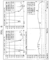
- FIG. 7 is a diagram illustrating isolation characteristics of the antenna for vehicles in accordance with the embodiment of the present invention.
- the antenna for vehicles in accordance with the embodiment of the present invention may include a GPS (Global Positioning System) antenna 30, a DMB (Digital Multimedia Broadcasting) antenna 40, a second LTE antenna 50, and a first LTE antenna 60.
- GPS Global Positioning System
- DMB Digital Multimedia Broadcasting
- the GPS antenna 30 is a ceramic patch antenna and may be installed at the front end so as to receive a GPS signal.
- the DMB antenna 40 may be installed at the back end so as to receive a DMB signal.
- the DMB antenna 40 may be connected to a main ground 21 formed on a printed circuit board (PCB) 20.
- the DMB antenna 40 may be formed with a meander structure on the PCB 20, in order to secure an electrical length.
- a metal plate with a cap structure may be electrically connected to the top surface of the PCB 20, in order to improve receive (Rx) performance.
- the DMB antenna 40 may be formed in a monopole type for isotropic emission in all directions of a vehicle.
- the GPS antenna 30 and the DMB antenna 40 operate as one-way receiving antennas.
- an LNA Low Noise Amplifier
- the first and second LTE antennas 60 and 50 may be formed with a monopole-type structure for isotropic emission in all directions of the vehicle, and perform two-way communication.
- the first and second LTE antennas 60 and 50 may operate in a passive manner to which an LNA is not applied. Therefore, unlike the GPS antenna 30 and the DMB antenna 40, no LNA may be formed on the PCB 20 at the bottom of the first and second LTE antennas 60 and 50.
- various structures may be formed to improve the performance of the first and second LTE antennas 60 and 50.
- a first LTE antenna signal port 80 connected to the first LTE antenna 60 and a second LTE antenna signal port 90 connected to the second LTE antenna 50 may be formed separately from each other. Through the first and second LTE antenna signal ports 80 and 90, signals of the first and second LTE antennas 60 and 50 may be inputted, respectively.
- the first and second LTE antennas 60 and 50 may installed on a support unit 70 formed of a synthetic material such as plastic.
- the support unit 70 may spatially support the first and second LTE antennas 60 and 50 to efficiently operate.
- the first and second LTE antennas 60 and 50 may be obliquely installed along the structure of the above-described support unit 70.
- the first and second LTE antenna signal ports 80 and 90 may be asymmetrically arranged in a left-right diagonal direction.
- the first and second LTE antenna signal ports 80 and 90 may be isolated as separately from each other as possible inside a case 10, while the first and second LTE antenna signal ports 80 and 90 are asymmetrically arranged in the left-right diagonal direction.
- the antenna isolation characteristic may be improved.
- the grounds of the first and second LTE antennas 60 and 50 may be separated from each other.
- a first LTE antenna ground 81 connected to the first LTE antenna 60 may be integrated with the main ground 21 formed on the PCB 20.
- second LTE antenna grounds 91 and 92 connected to the second LTE antenna 50 may be independently formed so as to be physically isolated from the main ground 21 formed on the PCB 20.
- the second LTE antenna grounds 91 and 92 may include a top ground 91 formed at the top part of the PCB 20 and a bottom ground 92 formed at the bottom part of the PCB 20.
- the top ground 91 and the bottom ground 92 may be electrically connected through a via hole (not illustrated).
- the top ground 91 and the bottom ground 92 may be restrictively formed on the top and bottom parts of the PCB 20, respectively.
- the second LTE antenna 50 may form a small electric field.
- the second LTE antenna grounds 91 and 92 may be electrically connected to the main ground 21 through current path units 93 and 94, respectively, and the isolation characteristic may be improved through the current path units 93 and 94.
- the current path units 93 and 94 may include a top current path unit 93 for electrically connecting the top ground 91 and the main ground 21 and a bottom current path unit 94 for electrically connecting the bottom ground 92 and the main ground 21.
- the current path units 93 and 94 may connect the top ground 91 and the bottom ground 92 to the main ground 21, respectively, so as to pass ground currents formed at the top ground 91 and the bottom ground 92 to the main ground 21.
- the current path units 93 and 94 may be formed between the second LTE grounds 91 and 92 and the main ground 21, and set to such lengths that the current intensity of the first LTE antenna 60 is opposite to the current intensity of the second LTE antenna 50.
- a difference in length between the current path units 93 and 94 may be set to (wavelength of operation frequency/4). In this case, a signal blocking characteristic and a current flow may be slowed down.
- the difference in length between the first LTE antenna grounds 81 and the second LTE antenna grounds 91 and 92 is set to (wavelength/4) such that the current intensity of the first LTE antenna ground 81 is opposite to the current intensity of the second LTE antenna grounds 91 and 92, the current interference between the first LTE antenna 60 and the second LTE antenna 50 may be minimized to obtain the isolation characteristic.
- the main ground 21 may be utilized to substantially prevent the reduction in performance of the second LTE antenna grounds 91 and 92, and the electric fields may be concentrated on the top ground 91 and the bottom ground 92 so as to further improve the peak gain of the second LTE antenna 50.
- FIGS. 4 and 5 illustrate the current flows of the first and second LTE antennas 60 and 50. Since the current flow of the first LTE antenna 60 illustrated in FIG. 4 has the opposite intensity of the current flow of the second LTE antenna 50 illustrated in FIG. 5 , the current interference between the first and second LTE antennas 60 and 50 may be significantly reduced.
- arrows illustrated in FIGS. 4 and 5 indicate the intensities of the current flows of the first and second LTE antennas 60 and 50.
- the antenna isolation characteristic may be improved.
- the minimization of the current interference between the first and second LTE antennas 60 and 50 may be achieved through the current paths of the second LTE antenna grounds 91 and 92.
- the difference in length between the current path units 93 and 94 may be set to (wavelength/4).
- the difference in length between the current path units 93 and 94 may be set to about 8.75cm.
- the transmission speed of signals inputted from the second LTE antenna 50 may slow down. Due to the difference of the transmission speed, a phase delay effect may be acquired. For example, when the current flow of the first LTE antenna 60 is maximized, the current flow of the second LTE antenna 50 may be minimized, and when the current flow of the first LTE antenna 60 is minimized, the current flow of the second LTE antenna 60 may be maximized.
- isolation between two LTE antennas may be relatively degraded.
- isolation at 800MHz is about -8dB, and does not satisfy a reference isolation of -10dB, at which two LTE antennas are normally operated.
- matching performance between the antennas may be degraded.
- matching performance between the first and second LTE antennas 60 and 50 may be improved, and impedance matching performance may be improved. Furthermore, the isolation between the first and second LTE antennas 60 and 50 may be improved to -14dB, compared to the conventional ground method.
- the first LTE antenna 81 and the second LTE antenna grounds 91 and 92 may be differentially applied, and the current paths of the first LTE antenna ground 81 and the second LTE antenna grounds 91 and 92 may be differentially applied to differently form the current flow speed between the two antennas.
- the current interference between the first and second LTE antennas 60 and 50 may be minimized, and the isolation may be improved.
Landscapes
- Engineering & Computer Science (AREA)
- Computer Networks & Wireless Communication (AREA)
- Remote Sensing (AREA)
- Details Of Aerials (AREA)
- Variable-Direction Aerials And Aerial Arrays (AREA)
Description
- The present invention relates to a antenna for vehicles, and more particularly, to a antenna for vehicles, which is capable of securing isolation between LTE (Long Term Evolution) antennas, thereby minimizing interference between the LTE antennas.
- In general, a vehicle antenna includes a GPS (Global Positioning System) antenna, a DMB (Digital Multimedia Broadcasting) antenna and the like.
- The GPS antenna and an XM patch antenna have a structure that emits signals to the top of a vehicle. Furthermore, TMU (Telematics management unit), HSDPA (High-Speed Downlink Packet Access), and DMB antennas have a structure that emits signals in all directions of a vehicle, and signal interference between the respective antennas is small.
- Recently, as the LTE (Long Term Evolution) specification is added to antennas for vehicles, isolation between the respective antennas has emerged as an important factor.
- Thus, the MIMO (Multiple Input Multiple Output) antenna design technique has been applied. Examples of the MIMO antenna design technique may include a method of inserting an isolation element, a method of applying a diversity technique, and a method of using a decoupling network.
- However, since the method of inserting an isolation element requires an additional space for an antenna, it is difficult to apply the method to a shark antenna. Furthermore, when the method of applying a diversity technique is used, it is difficult to intentionally change the position, direction, and polarization of an antenna. Furthermore, since the method of using a decoupling network can be applied only at a specific single frequency band, the method needs to be designed in a multi-band configuration in the case of LTE. Thus, the method of using a decouple network is not suitable for the method for securing isolation between MIMO antennas. Recently, a method for securing isolation using a new material has been developed. However, the method for securing isolation using a new material has a disadvantage in terms of price and mass production.
- The related art of the present invention is disclosed in
Korean Patent Laid-open Publication No. 10-2010-0104739 published on September 29, 2010 - An antenna assembly for a vehicle roof is known from
WO 2013/090783 A1 . The antenna assembly includes first and second cellular antennas. The first cellular antenna is connected to and supported by a printed circuit board via soldering of tabs formed at the bottom of the antenna. The second cellular antenna is also connected to and supported by the printed circuit board by soldering. The second cellular antenna further comprises an extending portion for electrically connecting to a ground plane. - It is an object of the present invention to provide an antenna for vehicles, which is capable of securing isolation between LTE antennas, thereby reducing interference between the LTE antennas and improving the communication speed of LTE data.
- This object is achieved by the subject matter of
claim 1. The dependent claims describe advantageous embodiments of the invention. - In one embodiment, an antenna for vehicles includes: a main ground formed on a printed circuit board (PCB); a first LTE antenna ground connected to the main ground so as to ground a signal of a first LTE antenna; and a second LTE antenna ground connected to the main ground so as to ground a signal of a second LTE antenna. The antenna further includes a current path unit configured to electrically connect the second LTE antenna ground to the main ground, wherein the current path unit is formed to a length of (wavelength of operation frequency/4). The first LTE antenna ground is integrated with the main ground.
- The first LTE antenna ground and the second LTE antenna ground may be left-right asymmetrically formed on the PCB.
- A signal port of the first LTE antenna and a signal port of the second LTE antenna may be arranged in a left-right diagonal direction.
- The second LTE antenna ground may be formed to be physically separated from the main ground.
- The second LTE antenna ground may include a top ground formed at the top part of the PCB and a bottom ground formed at the bottom part of the PCB, and the top ground and the bottom ground may be connected through a via hole.
- The first LTE antenna and the second LTE antenna may be formed in different shapes from each other.
- The first LTE antenna and the second LTE antenna may be formed to have different areas from each other.
- In accordance with the embodiments of the present invention, the antenna for vehicles may secure isolation between the LTE antennas, thereby reducing interference between the LTE antennas and improving LTE data communication speed.
-
-
FIG. 1 is a configuration diagram of an antenna for vehicles in accordance with an embodiment of the present invention. -
FIG. 2 is a diagram illustrating the ground structure of the top part of the antenna for vehicles in accordance with the embodiment of the present invention. -
FIG. 3 is a diagram illustrating the ground structure of the bottom part of the antenna for vehicles in accordance with the embodiment of the present invention. -
FIG. 4 is a diagram illustrating the ground current intensity of a second LTE (Long Term Evolution) antenna of the antenna for vehicles in accordance with the embodiment of the present invention. -
FIG. 5 is a diagram illustrating the ground current intensity of a first LTE antenna of the antenna for vehicles in accordance with the embodiment of the present invention. -
FIG. 6 is a diagram illustrating isolation characteristics of a conventional antenna for vehicles. -
FIG. 7 is a diagram illustrating isolation characteristics of the antenna for vehicles in accordance with the embodiment of the present invention. - Embodiments of the invention will hereinafter be described in detail with reference to the accompanying drawings. It should be noted that the drawings are not to precise scale and may be exaggerated in thickness of lines or sizes of components for descriptive convenience and clarity only. Furthermore, the terms as used herein are defined by taking functions of the invention into account and can be changed according to the custom or intention of users or operators. Therefore, definition of the terms should be made according to the overall disclosures set forth herein.
-
FIG. 1 is a configuration diagram of a antenna for vehicles in accordance with an embodiment of the present invention.FIG. 2 is a diagram illustrating the ground structure of the top part of the antenna for vehicles in accordance with the embodiment of the present invention.FIG. 3 is a diagram illustrating the ground structure of the bottom part of the antenna for vehicles in accordance with the embodiment of the present invention.FIG. 4 is a diagram illustrating the ground current intensity of a second LTE (Long Term Evolution) antenna of the antenna for vehicles in accordance with the embodiment of the present invention.FIG. 5 is a diagram illustrating the ground current intensity of a first LTE antenna of the antenna for vehicles in accordance with the embodiment of the present invention.FIG. 6 is a diagram illustrating isolation characteristics of a conventional antenna for vehicles.FIG. 7 is a diagram illustrating isolation characteristics of the antenna for vehicles in accordance with the embodiment of the present invention. - Referring to
FIG. 1 , the antenna for vehicles in accordance with the embodiment of the present invention may include a GPS (Global Positioning System) antenna 30, a DMB (Digital Multimedia Broadcasting)antenna 40, asecond LTE antenna 50, and afirst LTE antenna 60. - The GPS antenna 30 is a ceramic patch antenna and may be installed at the front end so as to receive a GPS signal. The
DMB antenna 40 may be installed at the back end so as to receive a DMB signal. - The
DMB antenna 40 may be connected to amain ground 21 formed on a printed circuit board (PCB) 20. TheDMB antenna 40 may be formed with a meander structure on thePCB 20, in order to secure an electrical length. Furthermore, a metal plate with a cap structure may be electrically connected to the top surface of thePCB 20, in order to improve receive (Rx) performance. TheDMB antenna 40 may be formed in a monopole type for isotropic emission in all directions of a vehicle. - The GPS antenna 30 and the
DMB antenna 40 operate as one-way receiving antennas. Thus, an LNA (Low Noise Amplifier) may be formed on thePCB 20 at the bottom of the GPS antenna 30 and theDMB antenna 40, in order to amplify a received signal. - On the other hand, the first and
second LTE antennas second LTE antennas DMB antenna 40, no LNA may be formed on thePCB 20 at the bottom of the first andsecond LTE antennas PCB 20 at the bottom of the first andsecond antennas second LTE antennas - A first LTE
antenna signal port 80 connected to thefirst LTE antenna 60 and a second LTEantenna signal port 90 connected to thesecond LTE antenna 50 may be formed separately from each other. Through the first and second LTEantenna signal ports second LTE antennas - The first and
second LTE antennas support unit 70 formed of a synthetic material such as plastic. Thesupport unit 70 may spatially support the first andsecond LTE antennas second LTE antennas support unit 70. - The first and second LTE
antenna signal ports - As illustrated in
FIG. 3 , the first and second LTEantenna signal ports case 10, while the first and second LTEantenna signal ports - Furthermore, the grounds of the first and
second LTE antennas - Referring to
FIGS. 2 and 3 , a firstLTE antenna ground 81 connected to thefirst LTE antenna 60 may be integrated with themain ground 21 formed on thePCB 20. - On the other hand, second
LTE antenna grounds second LTE antenna 50 may be independently formed so as to be physically isolated from themain ground 21 formed on thePCB 20. - The second
LTE antenna grounds top ground 91 formed at the top part of thePCB 20 and abottom ground 92 formed at the bottom part of thePCB 20. Thetop ground 91 and thebottom ground 92 may be electrically connected through a via hole (not illustrated). - Referring to
FIGS. 2 and 3 , thetop ground 91 and thebottom ground 92 may be restrictively formed on the top and bottom parts of thePCB 20, respectively. When thetop ground 91 and thebottom ground 92 have a small size, thesecond LTE antenna 50 may form a small electric field. - Typically, when a small electric field is formed, the amount of current flowing to the ground may decrease. However, as the small electric field is formed, the performance of the antenna may be degraded to reduce the gain of the antenna. Thus, the second
LTE antenna grounds main ground 21 throughcurrent path units current path units - The
current path units current path unit 93 for electrically connecting thetop ground 91 and themain ground 21 and a bottomcurrent path unit 94 for electrically connecting thebottom ground 92 and themain ground 21. - The
current path units top ground 91 and thebottom ground 92 to themain ground 21, respectively, so as to pass ground currents formed at thetop ground 91 and thebottom ground 92 to themain ground 21. - At this time, the
current path units second LTE grounds main ground 21, and set to such lengths that the current intensity of thefirst LTE antenna 60 is opposite to the current intensity of thesecond LTE antenna 50. For example, a difference in length between thecurrent path units - When the difference in length between the first
LTE antenna grounds 81 and the secondLTE antenna grounds LTE antenna ground 81 is opposite to the current intensity of the secondLTE antenna grounds first LTE antenna 60 and thesecond LTE antenna 50 may be minimized to obtain the isolation characteristic. - As a result, the
main ground 21 may be utilized to substantially prevent the reduction in performance of the secondLTE antenna grounds top ground 91 and thebottom ground 92 so as to further improve the peak gain of thesecond LTE antenna 50. -
FIGS. 4 and 5 illustrate the current flows of the first andsecond LTE antennas first LTE antenna 60 illustrated inFIG. 4 has the opposite intensity of the current flow of thesecond LTE antenna 50 illustrated inFIG. 5 , the current interference between the first andsecond LTE antennas - For reference, arrows illustrated in
FIGS. 4 and 5 indicate the intensities of the current flows of the first andsecond LTE antennas - As the current interference between the first and
second LTE antennas second LTE antennas LTE antenna grounds current path units current path units - That is, as the first and
second antennas second LTE antenna 50 may slow down. Due to the difference of the transmission speed, a phase delay effect may be acquired. For example, when the current flow of thefirst LTE antenna 60 is maximized, the current flow of thesecond LTE antenna 50 may be minimized, and when the current flow of thefirst LTE antenna 60 is minimized, the current flow of thesecond LTE antenna 60 may be maximized. - Referring to
FIGS. 6 and7 , when the conventional ground method is utilized, the same current flow may be formed in the ground. Thus, isolation between two LTE antennas may be relatively degraded. InFIG. 6 , isolation at 800MHz is about -8dB, and does not satisfy a reference isolation of -10dB, at which two LTE antennas are normally operated. Furthermore, since the same ground is utilized, matching performance between the antennas may be degraded. - On the other hand, in the antenna in accordance with the embodiment of the present invention, matching performance between the first and
second LTE antennas second LTE antennas - That is, in the antenna in accordance with the embodiment of the present invention, the
first LTE antenna 81 and the secondLTE antenna grounds LTE antenna ground 81 and the secondLTE antenna grounds second LTE antennas - Although preferred embodiments of the invention have been disclosed for illustrative purposes, those skilled in the art will appreciate that various modifications, additions and substitutions are possible, without departing from the invention as defined in the accompanying claims.
Claims (5)
- An antenna for vehicles, comprising:a main ground (21) formed on a printed circuit board (20);a first LTE antenna (60);a second LTE antenna (50);a first LTE antenna ground (81) connected to the main ground (21) so as to ground a signal of the first LTE antenna (60); anda second LTE antenna ground (91, 92) connected to the main ground (21) so as to ground a signal of the second LTE antenna (50),characterized bya current path unit (93) configured to electrically connect the second LTE antenna ground (91, 92) to the main ground (21), wherein the current path unit (93) is formed to a length of a quarter of a wavelength of an operation frequency, and wherein the first LTE antenna ground (81) is integrated with the main ground (21).
- The antenna of claim 1, wherein the second LTE antenna ground (91, 92) is formed to be physically separated from the main ground (21).
- The antenna of claim 2, wherein the second LTE antenna ground (91, 92) comprises a top ground (91) formed at the top part of the printed circuit board (20) and a bottom ground (92) formed at the bottom part of the printed circuit board (20), and
the top ground (91) and the bottom ground (92) are connected through a via hole. - The antenna of claim 1, wherein the first LTE antenna (60) and the second LTE antenna (50) are formed in different shapes from each other.
- The antenna of claim 1, wherein the first LTE antenna (60) and the second LTE antenna (50) are formed to have different areas from each other.
Applications Claiming Priority (1)
| Application Number | Priority Date | Filing Date | Title |
|---|---|---|---|
| KR1020130135129A KR102060300B1 (en) | 2013-11-08 | 2013-11-08 | Shark pin antenna for vehicles |
Publications (2)
| Publication Number | Publication Date |
|---|---|
| EP2871713A1 EP2871713A1 (en) | 2015-05-13 |
| EP2871713B1 true EP2871713B1 (en) | 2017-07-26 |
Family
ID=51846527
Family Applications (1)
| Application Number | Title | Priority Date | Filing Date |
|---|---|---|---|
| EP14191642.9A Active EP2871713B1 (en) | 2013-11-08 | 2014-11-04 | Antenna for vehicles |
Country Status (4)
| Country | Link |
|---|---|
| US (1) | US9917352B2 (en) |
| EP (1) | EP2871713B1 (en) |
| KR (1) | KR102060300B1 (en) |
| CN (1) | CN104638364B (en) |
Families Citing this family (6)
| Publication number | Priority date | Publication date | Assignee | Title |
|---|---|---|---|---|
| CN107851888B (en) * | 2015-06-11 | 2020-09-08 | 科递(上海)贸易有限公司 | Multiport multiband vehicular antenna assembly including multiple radiators |
| KR101622170B1 (en) * | 2015-08-20 | 2016-05-18 | 몰렉스 엘엘씨 | External antenna for vehicle |
| CN105552539A (en) * | 2015-12-22 | 2016-05-04 | 卜放 | Vehicle-mounted antenna |
| JP6964601B2 (en) * | 2016-12-16 | 2021-11-10 | 株式会社ヨコオ | Antenna device |
| KR102217182B1 (en) | 2018-11-19 | 2021-02-18 | 삼성전자주식회사 | Communication device for car |
| US20260106382A1 (en) * | 2024-10-16 | 2026-04-16 | Te Connectivity Solutions Gmbh | Vehicular antenna having a low-profile antenna assembly for non-metal surface and metal surface application |
Family Cites Families (5)
| Publication number | Priority date | Publication date | Assignee | Title |
|---|---|---|---|---|
| KR101050368B1 (en) | 2009-03-19 | 2011-07-20 | 주식회사 에이스테크놀로지 | Shade Band Antenna Installed in Vehicle |
| KR101129096B1 (en) * | 2011-01-11 | 2012-03-23 | 주식회사 에이스테크놀로지 | Shark pin antenna for automobile |
| CN103891043B (en) * | 2011-10-31 | 2015-11-25 | 索尼爱立信移动通讯有限公司 | Adopt multiple-input and multiple-output (MIMO) antenna of multiband trapper |
| CN104115329B (en) * | 2011-12-14 | 2016-06-29 | 莱尔德技术股份有限公司 | Can by many bands mimo antenna assembly of LTE frequency operation |
| KR20130102171A (en) * | 2012-03-07 | 2013-09-17 | 주식회사 팬택 | Wireless terminal with indirect feeding antenna |
-
2013
- 2013-11-08 KR KR1020130135129A patent/KR102060300B1/en active Active
-
2014
- 2014-07-31 CN CN201410373425.7A patent/CN104638364B/en active Active
- 2014-11-04 EP EP14191642.9A patent/EP2871713B1/en active Active
- 2014-11-07 US US14/536,304 patent/US9917352B2/en active Active
Non-Patent Citations (1)
| Title |
|---|
| None * |
Also Published As
| Publication number | Publication date |
|---|---|
| US20150130679A1 (en) | 2015-05-14 |
| KR102060300B1 (en) | 2019-12-30 |
| CN104638364A (en) | 2015-05-20 |
| EP2871713A1 (en) | 2015-05-13 |
| CN104638364B (en) | 2018-04-17 |
| US9917352B2 (en) | 2018-03-13 |
| KR20150053340A (en) | 2015-05-18 |
Similar Documents
| Publication | Publication Date | Title |
|---|---|---|
| US9917352B2 (en) | Antenna for vehicles | |
| CN102439791B (en) | GPS, GSM, and wireless LAN antenna for vehicle applications | |
| CN104466432B (en) | Multiband MIMO car antenna components with DSRC functions | |
| US8514134B2 (en) | MIMO antenna having parasitic elements | |
| US20140009360A1 (en) | Mobile communication device with improved antenna performance | |
| US8483749B2 (en) | Mobile terminal device for receiving dual band signal using multiple resonance antenna | |
| EP3462539B1 (en) | Multifunctional gnss antenna | |
| US9531084B2 (en) | Multiple input multiple output (MIMO) antennas having polarization and angle diversity and related wireless communications devices | |
| KR101622170B1 (en) | External antenna for vehicle | |
| US10396427B2 (en) | Dual polarized wideband LTE thin film antenna | |
| JP6041966B1 (en) | Composite patch antenna device | |
| US10374289B2 (en) | Reconfigurable 4-port multi-band multi-function antenna with a grounded dipole antenna component | |
| US9379430B2 (en) | Multiband antenna | |
| WO2016030038A2 (en) | Decoupled antennas for wireless communication | |
| US9178286B2 (en) | Antenna structure for MIMO application | |
| SE516482C2 (en) | Patch antenna and a communication equipment including such an antenna | |
| US9419327B2 (en) | System for radiating radio frequency signals | |
| KR101945070B1 (en) | Internal unified antenna module for vehicle | |
| US20060103581A1 (en) | Multiband concentric mast and microstrip patch antenna arrangement | |
| WO2011049351A2 (en) | Multi-band antenna using an lc filter | |
| CN111613885A (en) | Radiators for Antennas and Base Station Antennas | |
| CA2586503A1 (en) | Improved ground plane patch antenna |
Legal Events
| Date | Code | Title | Description |
|---|---|---|---|
| PUAI | Public reference made under article 153(3) epc to a published international application that has entered the european phase |
Free format text: ORIGINAL CODE: 0009012 |
|
| 17P | Request for examination filed |
Effective date: 20141104 |
|
| AK | Designated contracting states |
Kind code of ref document: A1 Designated state(s): AL AT BE BG CH CY CZ DE DK EE ES FI FR GB GR HR HU IE IS IT LI LT LU LV MC MK MT NL NO PL PT RO RS SE SI SK SM TR |
|
| AX | Request for extension of the european patent |
Extension state: BA ME |
|
| RBV | Designated contracting states (corrected) |
Designated state(s): AL AT BE BG CH CY CZ DE DK EE ES FI FR GB GR HR HU IE IS IT LI LT LU LV MC MK MT NL NO PL PT RO RS SE SI SK SM TR |
|
| 17Q | First examination report despatched |
Effective date: 20160405 |
|
| GRAP | Despatch of communication of intention to grant a patent |
Free format text: ORIGINAL CODE: EPIDOSNIGR1 |
|
| RIC1 | Information provided on ipc code assigned before grant |
Ipc: H01Q 1/48 20060101ALI20170126BHEP Ipc: H01Q 1/38 20060101ALN20170126BHEP Ipc: H01Q 1/24 20060101ALI20170126BHEP Ipc: H01Q 1/27 20060101ALI20170126BHEP Ipc: H01Q 1/32 20060101AFI20170126BHEP Ipc: H01Q 21/28 20060101ALI20170126BHEP |
|
| INTG | Intention to grant announced |
Effective date: 20170210 |
|
| RAP1 | Party data changed (applicant data changed or rights of an application transferred) |
Owner name: HYUNDAI MOBIS CO., LTD. Owner name: INFAC ELECS CO., LTD. |
|
| RIC1 | Information provided on ipc code assigned before grant |
Ipc: H01Q 1/27 20060101ALI20170130BHEP Ipc: H01Q 1/48 20060101ALI20170130BHEP Ipc: H01Q 1/24 20060101ALI20170130BHEP Ipc: H01Q 1/32 20060101AFI20170130BHEP Ipc: H01Q 1/38 20060101ALN20170130BHEP Ipc: H01Q 21/28 20060101ALI20170130BHEP |
|
| RIN1 | Information on inventor provided before grant (corrected) |
Inventor name: LEE, WON JONG Inventor name: YANG, SONG HEE Inventor name: SHIN, KYOUNG SUP Inventor name: KIM, WOO JIN |
|
| GRAS | Grant fee paid |
Free format text: ORIGINAL CODE: EPIDOSNIGR3 |
|
| GRAA | (expected) grant |
Free format text: ORIGINAL CODE: 0009210 |
|
| AK | Designated contracting states |
Kind code of ref document: B1 Designated state(s): AL AT BE BG CH CY CZ DE DK EE ES FI FR GB GR HR HU IE IS IT LI LT LU LV MC MK MT NL NO PL PT RO RS SE SI SK SM TR |
|
| REG | Reference to a national code |
Ref country code: GB Ref legal event code: FG4D |
|
| REG | Reference to a national code |
Ref country code: CH Ref legal event code: EP |
|
| REG | Reference to a national code |
Ref country code: AT Ref legal event code: REF Ref document number: 913100 Country of ref document: AT Kind code of ref document: T Effective date: 20170815 |
|
| REG | Reference to a national code |
Ref country code: IE Ref legal event code: FG4D |
|
| REG | Reference to a national code |
Ref country code: DE Ref legal event code: R096 Ref document number: 602014012207 Country of ref document: DE |
|
| REG | Reference to a national code |
Ref country code: FR Ref legal event code: PLFP Year of fee payment: 4 |
|
| REG | Reference to a national code |
Ref country code: NL Ref legal event code: MP Effective date: 20170726 |
|
| REG | Reference to a national code |
Ref country code: LT Ref legal event code: MG4D |
|
| REG | Reference to a national code |
Ref country code: AT Ref legal event code: MK05 Ref document number: 913100 Country of ref document: AT Kind code of ref document: T Effective date: 20170726 |
|
| PG25 | Lapsed in a contracting state [announced via postgrant information from national office to epo] |
Ref country code: AT Free format text: LAPSE BECAUSE OF FAILURE TO SUBMIT A TRANSLATION OF THE DESCRIPTION OR TO PAY THE FEE WITHIN THE PRESCRIBED TIME-LIMIT Effective date: 20170726 Ref country code: FI Free format text: LAPSE BECAUSE OF FAILURE TO SUBMIT A TRANSLATION OF THE DESCRIPTION OR TO PAY THE FEE WITHIN THE PRESCRIBED TIME-LIMIT Effective date: 20170726 Ref country code: NO Free format text: LAPSE BECAUSE OF FAILURE TO SUBMIT A TRANSLATION OF THE DESCRIPTION OR TO PAY THE FEE WITHIN THE PRESCRIBED TIME-LIMIT Effective date: 20171026 Ref country code: SE Free format text: LAPSE BECAUSE OF FAILURE TO SUBMIT A TRANSLATION OF THE DESCRIPTION OR TO PAY THE FEE WITHIN THE PRESCRIBED TIME-LIMIT Effective date: 20170726 Ref country code: NL Free format text: LAPSE BECAUSE OF FAILURE TO SUBMIT A TRANSLATION OF THE DESCRIPTION OR TO PAY THE FEE WITHIN THE PRESCRIBED TIME-LIMIT Effective date: 20170726 Ref country code: HR Free format text: LAPSE BECAUSE OF FAILURE TO SUBMIT A TRANSLATION OF THE DESCRIPTION OR TO PAY THE FEE WITHIN THE PRESCRIBED TIME-LIMIT Effective date: 20170726 Ref country code: LT Free format text: LAPSE BECAUSE OF FAILURE TO SUBMIT A TRANSLATION OF THE DESCRIPTION OR TO PAY THE FEE WITHIN THE PRESCRIBED TIME-LIMIT Effective date: 20170726 |
|
| PG25 | Lapsed in a contracting state [announced via postgrant information from national office to epo] |
Ref country code: RS Free format text: LAPSE BECAUSE OF FAILURE TO SUBMIT A TRANSLATION OF THE DESCRIPTION OR TO PAY THE FEE WITHIN THE PRESCRIBED TIME-LIMIT Effective date: 20170726 Ref country code: BG Free format text: LAPSE BECAUSE OF FAILURE TO SUBMIT A TRANSLATION OF THE DESCRIPTION OR TO PAY THE FEE WITHIN THE PRESCRIBED TIME-LIMIT Effective date: 20171026 Ref country code: ES Free format text: LAPSE BECAUSE OF FAILURE TO SUBMIT A TRANSLATION OF THE DESCRIPTION OR TO PAY THE FEE WITHIN THE PRESCRIBED TIME-LIMIT Effective date: 20170726 Ref country code: PL Free format text: LAPSE BECAUSE OF FAILURE TO SUBMIT A TRANSLATION OF THE DESCRIPTION OR TO PAY THE FEE WITHIN THE PRESCRIBED TIME-LIMIT Effective date: 20170726 Ref country code: GR Free format text: LAPSE BECAUSE OF FAILURE TO SUBMIT A TRANSLATION OF THE DESCRIPTION OR TO PAY THE FEE WITHIN THE PRESCRIBED TIME-LIMIT Effective date: 20171027 Ref country code: LV Free format text: LAPSE BECAUSE OF FAILURE TO SUBMIT A TRANSLATION OF THE DESCRIPTION OR TO PAY THE FEE WITHIN THE PRESCRIBED TIME-LIMIT Effective date: 20170726 Ref country code: IS Free format text: LAPSE BECAUSE OF FAILURE TO SUBMIT A TRANSLATION OF THE DESCRIPTION OR TO PAY THE FEE WITHIN THE PRESCRIBED TIME-LIMIT Effective date: 20171126 |
|
| PG25 | Lapsed in a contracting state [announced via postgrant information from national office to epo] |
Ref country code: DK Free format text: LAPSE BECAUSE OF FAILURE TO SUBMIT A TRANSLATION OF THE DESCRIPTION OR TO PAY THE FEE WITHIN THE PRESCRIBED TIME-LIMIT Effective date: 20170726 Ref country code: RO Free format text: LAPSE BECAUSE OF FAILURE TO SUBMIT A TRANSLATION OF THE DESCRIPTION OR TO PAY THE FEE WITHIN THE PRESCRIBED TIME-LIMIT Effective date: 20170726 Ref country code: CZ Free format text: LAPSE BECAUSE OF FAILURE TO SUBMIT A TRANSLATION OF THE DESCRIPTION OR TO PAY THE FEE WITHIN THE PRESCRIBED TIME-LIMIT Effective date: 20170726 |
|
| REG | Reference to a national code |
Ref country code: DE Ref legal event code: R097 Ref document number: 602014012207 Country of ref document: DE |
|
| PG25 | Lapsed in a contracting state [announced via postgrant information from national office to epo] |
Ref country code: IT Free format text: LAPSE BECAUSE OF FAILURE TO SUBMIT A TRANSLATION OF THE DESCRIPTION OR TO PAY THE FEE WITHIN THE PRESCRIBED TIME-LIMIT Effective date: 20170726 Ref country code: EE Free format text: LAPSE BECAUSE OF FAILURE TO SUBMIT A TRANSLATION OF THE DESCRIPTION OR TO PAY THE FEE WITHIN THE PRESCRIBED TIME-LIMIT Effective date: 20170726 Ref country code: SM Free format text: LAPSE BECAUSE OF FAILURE TO SUBMIT A TRANSLATION OF THE DESCRIPTION OR TO PAY THE FEE WITHIN THE PRESCRIBED TIME-LIMIT Effective date: 20170726 Ref country code: SK Free format text: LAPSE BECAUSE OF FAILURE TO SUBMIT A TRANSLATION OF THE DESCRIPTION OR TO PAY THE FEE WITHIN THE PRESCRIBED TIME-LIMIT Effective date: 20170726 |
|
| PLBE | No opposition filed within time limit |
Free format text: ORIGINAL CODE: 0009261 |
|
| STAA | Information on the status of an ep patent application or granted ep patent |
Free format text: STATUS: NO OPPOSITION FILED WITHIN TIME LIMIT |
|
| PG25 | Lapsed in a contracting state [announced via postgrant information from national office to epo] |
Ref country code: MC Free format text: LAPSE BECAUSE OF FAILURE TO SUBMIT A TRANSLATION OF THE DESCRIPTION OR TO PAY THE FEE WITHIN THE PRESCRIBED TIME-LIMIT Effective date: 20170726 |
|
| 26N | No opposition filed |
Effective date: 20180430 |
|
| PG25 | Lapsed in a contracting state [announced via postgrant information from national office to epo] |
Ref country code: CH Free format text: LAPSE BECAUSE OF NON-PAYMENT OF DUE FEES Effective date: 20171130 Ref country code: LI Free format text: LAPSE BECAUSE OF NON-PAYMENT OF DUE FEES Effective date: 20171130 |
|
| PG25 | Lapsed in a contracting state [announced via postgrant information from national office to epo] |
Ref country code: LU Free format text: LAPSE BECAUSE OF NON-PAYMENT OF DUE FEES Effective date: 20171104 Ref country code: SI Free format text: LAPSE BECAUSE OF FAILURE TO SUBMIT A TRANSLATION OF THE DESCRIPTION OR TO PAY THE FEE WITHIN THE PRESCRIBED TIME-LIMIT Effective date: 20170726 |
|
| REG | Reference to a national code |
Ref country code: BE Ref legal event code: MM Effective date: 20171130 |
|
| REG | Reference to a national code |
Ref country code: IE Ref legal event code: MM4A |
|
| PG25 | Lapsed in a contracting state [announced via postgrant information from national office to epo] |
Ref country code: MT Free format text: LAPSE BECAUSE OF NON-PAYMENT OF DUE FEES Effective date: 20171104 |
|
| REG | Reference to a national code |
Ref country code: FR Ref legal event code: PLFP Year of fee payment: 5 |
|
| PG25 | Lapsed in a contracting state [announced via postgrant information from national office to epo] |
Ref country code: IE Free format text: LAPSE BECAUSE OF NON-PAYMENT OF DUE FEES Effective date: 20171104 |
|
| PG25 | Lapsed in a contracting state [announced via postgrant information from national office to epo] |
Ref country code: BE Free format text: LAPSE BECAUSE OF NON-PAYMENT OF DUE FEES Effective date: 20171130 |
|
| PG25 | Lapsed in a contracting state [announced via postgrant information from national office to epo] |
Ref country code: HU Free format text: LAPSE BECAUSE OF FAILURE TO SUBMIT A TRANSLATION OF THE DESCRIPTION OR TO PAY THE FEE WITHIN THE PRESCRIBED TIME-LIMIT; INVALID AB INITIO Effective date: 20141104 |
|
| REG | Reference to a national code |
Ref country code: DE Ref legal event code: R082 Ref document number: 602014012207 Country of ref document: DE Representative=s name: GRUENECKER PATENT- UND RECHTSANWAELTE PARTG MB, DE Ref country code: DE Ref legal event code: R081 Ref document number: 602014012207 Country of ref document: DE Owner name: HYUNDAI MOBIS CO., LTD., KR Free format text: FORMER OWNERS: HYUNDAI MOBIS CO., LTD., SEOUL, KR; INFAC ELECS CO., LTD., INCHEON, KR |
|
| GBPC | Gb: european patent ceased through non-payment of renewal fee |
Effective date: 20181104 |
|
| PG25 | Lapsed in a contracting state [announced via postgrant information from national office to epo] |
Ref country code: CY Free format text: LAPSE BECAUSE OF FAILURE TO SUBMIT A TRANSLATION OF THE DESCRIPTION OR TO PAY THE FEE WITHIN THE PRESCRIBED TIME-LIMIT Effective date: 20170726 |
|
| PG25 | Lapsed in a contracting state [announced via postgrant information from national office to epo] |
Ref country code: MK Free format text: LAPSE BECAUSE OF FAILURE TO SUBMIT A TRANSLATION OF THE DESCRIPTION OR TO PAY THE FEE WITHIN THE PRESCRIBED TIME-LIMIT Effective date: 20170726 |
|
| PG25 | Lapsed in a contracting state [announced via postgrant information from national office to epo] |
Ref country code: GB Free format text: LAPSE BECAUSE OF NON-PAYMENT OF DUE FEES Effective date: 20181104 |
|
| PG25 | Lapsed in a contracting state [announced via postgrant information from national office to epo] |
Ref country code: TR Free format text: LAPSE BECAUSE OF FAILURE TO SUBMIT A TRANSLATION OF THE DESCRIPTION OR TO PAY THE FEE WITHIN THE PRESCRIBED TIME-LIMIT Effective date: 20170726 |
|
| PG25 | Lapsed in a contracting state [announced via postgrant information from national office to epo] |
Ref country code: PT Free format text: LAPSE BECAUSE OF FAILURE TO SUBMIT A TRANSLATION OF THE DESCRIPTION OR TO PAY THE FEE WITHIN THE PRESCRIBED TIME-LIMIT Effective date: 20170726 |
|
| PG25 | Lapsed in a contracting state [announced via postgrant information from national office to epo] |
Ref country code: AL Free format text: LAPSE BECAUSE OF FAILURE TO SUBMIT A TRANSLATION OF THE DESCRIPTION OR TO PAY THE FEE WITHIN THE PRESCRIBED TIME-LIMIT Effective date: 20170726 |
|
| P01 | Opt-out of the competence of the unified patent court (upc) registered |
Effective date: 20230530 |
|
| PGFP | Annual fee paid to national office [announced via postgrant information from national office to epo] |
Ref country code: FR Payment date: 20250925 Year of fee payment: 12 |
|
| PGFP | Annual fee paid to national office [announced via postgrant information from national office to epo] |
Ref country code: DE Payment date: 20250922 Year of fee payment: 12 |