EP2871636A1 - Sound reduction system - Google Patents
Sound reduction system Download PDFInfo
- Publication number
- EP2871636A1 EP2871636A1 EP20130192055 EP13192055A EP2871636A1 EP 2871636 A1 EP2871636 A1 EP 2871636A1 EP 20130192055 EP20130192055 EP 20130192055 EP 13192055 A EP13192055 A EP 13192055A EP 2871636 A1 EP2871636 A1 EP 2871636A1
- Authority
- EP
- European Patent Office
- Prior art keywords
- sound
- sound reduction
- frame
- channel
- reduction device
- Prior art date
- Legal status (The legal status is an assumption and is not a legal conclusion. Google has not performed a legal analysis and makes no representation as to the accuracy of the status listed.)
- Granted
Links
Images


Classifications
-
- B—PERFORMING OPERATIONS; TRANSPORTING
- B60—VEHICLES IN GENERAL
- B60R—VEHICLES, VEHICLE FITTINGS, OR VEHICLE PARTS, NOT OTHERWISE PROVIDED FOR
- B60R13/00—Elements for body-finishing, identifying, or decorating; Arrangements or adaptations for advertising purposes
- B60R13/08—Insulating elements, e.g. for sound insulation
- B60R13/0846—Insulating elements, e.g. for sound insulation for duct, cable or rod passages, e.g. between engine and passenger compartments
-
- F—MECHANICAL ENGINEERING; LIGHTING; HEATING; WEAPONS; BLASTING
- F16—ENGINEERING ELEMENTS AND UNITS; GENERAL MEASURES FOR PRODUCING AND MAINTAINING EFFECTIVE FUNCTIONING OF MACHINES OR INSTALLATIONS; THERMAL INSULATION IN GENERAL
- F16L—PIPES; JOINTS OR FITTINGS FOR PIPES; SUPPORTS FOR PIPES, CABLES OR PROTECTIVE TUBING; MEANS FOR THERMAL INSULATION IN GENERAL
- F16L55/00—Devices or appurtenances for use in, or in connection with, pipes or pipe systems
- F16L55/02—Energy absorbers; Noise absorbers
- F16L55/033—Noise absorbers
-
- F—MECHANICAL ENGINEERING; LIGHTING; HEATING; WEAPONS; BLASTING
- F16—ENGINEERING ELEMENTS AND UNITS; GENERAL MEASURES FOR PRODUCING AND MAINTAINING EFFECTIVE FUNCTIONING OF MACHINES OR INSTALLATIONS; THERMAL INSULATION IN GENERAL
- F16L—PIPES; JOINTS OR FITTINGS FOR PIPES; SUPPORTS FOR PIPES, CABLES OR PROTECTIVE TUBING; MEANS FOR THERMAL INSULATION IN GENERAL
- F16L55/00—Devices or appurtenances for use in, or in connection with, pipes or pipe systems
- F16L55/02—Energy absorbers; Noise absorbers
- F16L55/033—Noise absorbers
- F16L55/0336—Noise absorbers by means of sound-absorbing materials
-
- G—PHYSICS
- G10—MUSICAL INSTRUMENTS; ACOUSTICS
- G10K—SOUND-PRODUCING DEVICES; METHODS OR DEVICES FOR PROTECTING AGAINST, OR FOR DAMPING, NOISE OR OTHER ACOUSTIC WAVES IN GENERAL; ACOUSTICS NOT OTHERWISE PROVIDED FOR
- G10K11/00—Methods or devices for transmitting, conducting or directing sound in general; Methods or devices for protecting against, or for damping, noise or other acoustic waves in general
- G10K11/002—Devices for damping, suppressing, obstructing or conducting sound in acoustic devices
-
- G—PHYSICS
- G10—MUSICAL INSTRUMENTS; ACOUSTICS
- G10K—SOUND-PRODUCING DEVICES; METHODS OR DEVICES FOR PROTECTING AGAINST, OR FOR DAMPING, NOISE OR OTHER ACOUSTIC WAVES IN GENERAL; ACOUSTICS NOT OTHERWISE PROVIDED FOR
- G10K11/00—Methods or devices for transmitting, conducting or directing sound in general; Methods or devices for protecting against, or for damping, noise or other acoustic waves in general
- G10K11/16—Methods or devices for protecting against, or for damping, noise or other acoustic waves in general
- G10K11/161—Methods or devices for protecting against, or for damping, noise or other acoustic waves in general in systems with fluid flow
Definitions
- the invention relates to a sound reduction system comprising a sound reduction device.
- the sound reduction device comprises a sound reducing material.
- the system further comprises a channel wherein a gaseous medium is arranged to flow.
- the invention further relates to a method for reducing sound.
- Noise is a big source of concern in today's society.
- Various types of machines emit sounds of various frequencies. Certain frequencies louder than a certain decibel level are considered noise and must due to for instance regulations be removed or reduced to below an allowable decibel level.
- One example of such a machine is any type of engine, pump or similar emitting sound which is considered noise which cannot be dampened or absorbed with standard sound absorbing or sound reducing means, such as resonators or insulation. This sound can be transported to various parts of the engine and also to parts separate from the engine through equipment attached to the engine.
- the object of the present invention is to provide a sound reduction system where the previously mentioned problems are avoided. This object is achieved by the features of the characterising portion of claim 1. Additional features of the invention are set out in the dependent claims. An additional object of the invention is to provide a method for reducing sound. This object is achieved by the features of claim 15.
- the invention relates to a sound reduction system comprising a sound reduction device.
- the sound reduction device comprises a sound reducing material.
- the system further comprises a channel wherein a gaseous medium is arranged to flow.
- the sound reduction device is mounted inside the channel, thereby placing the sound reducing material inside the channel.
- the effect is that sound reducing material is placed inside the channel. This leads to that sound propagating in the gaseous medium inside the channel can be reduced. This is advantageous when, as described above, there is no room for additional sound reducing or sound absorbing systems or devices which needs to be placed on the outside of the channel.
- the channel may for instance be an air intake duct on a vehicle engine, a ventilation duct in a ventilation system or a pipe in which a gaseous medium flows in for instance a processing plant such as a refinery or a paper mill.
- the system according to the invention may also be advantageous if changes to for instance an engine, fan or pump design lead to that the frequency spectrum in the generated sound is changed and all frequencies cannot be reduced in the current design.
- the sound reduction device can be adapted to dampen and/or absorb sound over a narrow frequency range or a large frequency range depending on the type and design of sound reducing material used in the sound reduction device.
- the sound reduction device may comprise a supporting structure and a frame arranged to be supported by the supporting structure.
- the sound reducing material is placed in the frame.
- the frame comprises the sound reducing material and is supported by the supporting structure which allows for an easy placement of the sound reducing material inside the channel.
- the supporting structure of the sound reduction device may be a closed structure.
- the frame may be placed in the supporting structure such that the sound reducing material is located inside the supporting structure.
- the supporting structure can take the shape of a closed structure.
- closed structure means a structure which for instance is circular, oval, rectangular or any similar shape.
- a closed structure provides for a better structural integrity of the supporting structure.
- the supporting structure may of course be open, such as for instance taking the shape of a semi-circle, a semi-oval or a semi-rectangle and similar shapes.
- the supporting structure may comprise a collar.
- the collar is a part of the supporting structure which is wider than the remainder of the supporting structure.
- the collar can for instance take the shape of an elevated rim on the supporting structure. The collar ensures that the sound reduction device stays in place when mounted and prevents the sound reduction device from becoming dismounted from its intended mounting location.
- the sound reduction device may be removably mounted inside the channel.
- the sound reduction device may be securely mounted inside the channel for instance by welding, gluing or by any other means of attaching the sound reduction device to the channel.
- the collar may allow for an easy removal of the sound reduction device as it may be undesirable to grab for instance the frame in order to remove the sound reduction device.
- the sound reducing material may be a solid member placed in the frame and/or the sound reducing material may comprise a fibre mat placed in the frame. Depending on the type of sound being generated the sound reduction device can be adapted accordingly by changing the type of sound reducing material placed in the frame.
- a solid member can be placed in the frame.
- a fibre mat can be placed in the frame.
- a fibre mat is fibre material formed into a desired shape. The fibre mat effectively absorbs the sound energy of the sound frequencies and converts these to heat inside the fibre mat thereby reducing the sound energy of these frequencies.
- the frequencies reduced is determined by the choice of sound reducing material, i.e. solid member or fibre mat; the volume of the frame, i.e. the amount of material placed in the frame; and the area of the frame. Other characteristics related to volume and area such as length of the frame and the width of the frame can be used to tune the frequency spectrum targeted.
- the solid member and the fibre mat can be used alone or in combination. If used in combination one solid member can be placed together with a fibre mat or one solid member can be sandwiched between two fibre mats. Other combinations of solid members and fibre mats are of course conceivable.
- the sound reduction device may further comprise a fastening arrangement attached to the frame, thereby keeping the sound reducing material from escaping from the frame.
- a fastening arrangement may be used in order to ensure that the sound reducing material stays in the frame. This is primarily used when a fibre mat is used.
- the sound reduction device may be arranged to be disassembled.
- the sound reducing material may be one of or a combination of plastic, metal, glass fibre, polar fleece or polyurethane.
- the plastic or metal may be perforated in order to change the characteristics of the sound reduction.
- micro-perforated plates and their manufacture is described in WO 97/27370 .
- the frame may be aerodynamically shaped such that the pressure drop of the gaseous medium over the frame is reduced.
- the sound reduction device As the sound reduction device is placed in the path of a flowing gaseous medium a pressure drop will be experienced when the gaseous medium passes the sound reduction device.
- the sound reduction device In order to reduce the pressure drop the sound reduction device is made to take an aerodynamical shape.
- a cross-section along the length direction of the frame may for instance be wing-shaped.
- the sound reduction device may also follow the shape of the channel if the channel is not straight where the sound reduction device is mounted.
- the supporting structure and frame may be made of a plastic and/or a metal such as aluminium or stainless steel, the supporting structure and frame preferably being made of the same material as the channel in which it is placed. Having the sound reduction device and the channel made of the same material is preferable as wear will be similar to the channel and the sound reduction device. Galvanic risks are also reduced by having the same material, especially for metal wear or design. This for instance leads to that service intervals will not have to be determined by material wear in the sound reduction device.
- the pressure of the gas in the channel can be above atmospheric pressure, at atmospheric pressure or below atmospheric pressure.
- the sound reduction system can thus be used in any kind of pressure conditions in the channel.
- the system according to the invention can be placed in a vehicle where the channel in which the sound reduction device is placed is an air intake channel in the engine.
- the invention further relates to a method for reducing sound in a channel wherein a gaseous medium flows.
- the method comprises:
- the method may further comprise:
- FIG. 1 schematically shows a sound reduction device 1 used in a sound reduction system (not shown) according to the invention.
- the sound reduction device 1 comprises a supporting structure 2 and a frame 3.
- the frame 3 is arranged to be supported by the supporting structure 2.
- a sound reducing material 4 is placed in the frame 3.
- the sound reduction device 1 further comprises fastening means 5 arranged to secure the frame 3 to the supporting structure 2 by means of interacting with openings 6 in the supporting structure 2.
- the frame 3 has a length L measured from a frame front edge 7 to a frame rear edge 8.
- the frame 3 further has a thickness T measured from a top side 9 of the frame 3 to a bottom side 10 of the frame 3 and a width W measured in a direction perpendicular to both the thickness T and the length L.
- the length L, thickness T and width W determines the area and volume of the frame 3. The area and volume are adapted depending on which frequencies are desired to reduce.
- the thickness T can be the same over the entire length L of the frame or vary over the entire length L.
- the width W can be the same over the entire length L and/or thickness T or vary over the length L and/or thickness T.
- the frame 3 is supported by the supporting structure 2 such that the sound reducing material 4 is located inside the supporting structure 2. It is possible to have other configurations wherein the frame 3 is supported by the supporting structure 2 such that the sound reducing material 4 is located outside of the supporting structure 2.
- the supporting structure 2 in figure 1 is closed and is essentially oval shaped.
- the supporting structure 2 further comprises a collar 11 located along a front edge () of the supporting structure 2.
- the collar 11 is a portion of the supporting structure 2 which has a larger circumference than the remaining supporting structure 2.
- the frame 3 is aerodynamically shaped with a cross section in the shape of an airfoil or wing.
- the frame 3 may be curved as in figure 1 , but it may also be straight depending on the desired characteristics of the frame 3.
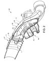
- FIG. 2 schematically shows a sound reduction system 12 according to the invention.
- the sound reduction system 12 comprises a channel 13 and a sound reduction device 1 mounted inside the channel 13. This particular system is taken from a vehicle engine (not shown) where the channel 13 is an air intake channel.
- the sound reduction device 1 is placed after the air filter (not shown), i.e. the gaseous medium is in this case clean air.
- the sound reduction device 1 is placed before a compressor (not shown) in the clean air system of the engine.
- the sound reduction device 1 is placed inside the channel 13 such that it does not interfere with the resonator openings 15 thereby complementing already present sound reducing components of the engine.
- the channel 13 in figure 2 comprises a first channel part 16 and a second channel part 17.
- the first channel part 16 is enclosed by the second channel part 17.
- the sound reduction device 1 is mounted in the channel 13 such that the collar 11 rests against a first channel part edge 18. This arrangement allows for the sound reducing material 4 to be placed in the desired location in the channel 13.
- the location of the sound reducing material 4 in the channel 13 is determined by the shape of the channel 13 and the location of other sound reducing components.
- Adapting the supporting structure 2 and the placement of the sound reducing material 4 in relation to each other are adaptations which fall well within the scope of the invention.
- the frame 3 follows the curved shape of the channel 13 as well as having a cross section which is aerodynamic. This ensures that a low pressure drop is achieved over the sound reduction device 1.
- the frame 3 is placed horizontally in the channel 13 in figure 2 . This is merely an example of an orientation of the frame 3.
- the frame 3 can be oriented vertically or at an angle between horizontally and vertically.
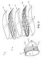
- Figure 3 schematically shows an exploded view of a sound reduction device 1 according to the invention.
- Figure 3 illustrates how the sound reduction device 1 is assembled and similarly can be disassembled.
- the frame 3 comprises a first frame part 19 and a second frame part 20 in between which a sound reducing material 4 is placed. This is in this example illustrated by a solid member.
- the first frame part 19 and second frame part 20 are after being assembled optionally covered by a first fastening arrangement 21 and a second fastening arrangement 22.
- the first fastening arrangement 21 and second fastening arrangement 22 are, as described above mainly used when a fibre mat is placed in between the first frame part 19 and second frame part 20.
- After assembly of the frame 3 the frame 3 is inserted into the supporting structure 2.
- Fastening means 5 on the frame 3 may form for instance a snap-in connection with the corresponding openings 6 on the supporting structure 2.
- the supporting structure 2 is preferably flexible such that it expands when the frame 3 is inserted, thereby ensuring a secure snap-in fit with the frame 3.
- the fastening means 5 comprises in this example three protrusions on each longitudinal side interacting with corresponding openings on the supporting structure 2.
- the fastening means 5 may alternatively take the shape of rails or a similar elongated protrusion on the frame 3 and a corresponding elongate slit on the supporting structure 2.
- the sound reduction device 1 can be disassembled in the reverse order.
- the fastening means 5 can alternatively to a snap-in connection be melted or welded, depending on the material of the supporting structure 2 and frame 3, to firmly secure the frame 3 to the supporting structure 2.
- the first frame part 19 and second frame part 20 can similarly be assembled securely by melting or welding, or have frame fastening means (not shown) which allows disassembly of the frame 3.
- Figure 4 schematically shows a diagram showing the effect of the sound reduction system 12 in an engine with the system installed compared to an engine without the system.
- the x-axis in the diagram represents frequency measured in Hz.
- the y-axis represents the measurement of the sound pressure measured in dB(A).
- the dashed line indicates measurements made without the sound reducing system. As can be seen for some frequencies around 2200 Hz and 2500 Hz the sound pressure exceeds 100 dB(A).
- the solid line represents measurements made with the sound reduction system 12. For higher frequencies above ca 1150 Hz a reduction in the sound pressure can be observed. The effect in this particular example is greatest for higher frequencies and it can be observed that sound pressure does not exceed 100 dB(A) for any frequencies measured.
- the diagram is merely intended to illustrate the effect of the inventive system and is not to be seen as a limiting example.
- the invention depending on the design of the sound reduction device 1, is effective over a wider frequency range than illustrated in figure 4 .
- Figures 2 and 4 relate to an air intake duct in a vehicle engine. This is merely an illustrative example of the invention and is not intended to be limiting for the application of the invention. Alternative applications wherein similar effects can be achieved can for instance be in channels in a ventilation system or in a system comprising a pump pumping a gaseous medium.
Landscapes
- Engineering & Computer Science (AREA)
- Physics & Mathematics (AREA)
- Acoustics & Sound (AREA)
- Multimedia (AREA)
- General Engineering & Computer Science (AREA)
- Mechanical Engineering (AREA)
- Fluid Mechanics (AREA)
- Combustion & Propulsion (AREA)
- Aviation & Aerospace Engineering (AREA)
- Chemical & Material Sciences (AREA)
- Vehicle Interior And Exterior Ornaments, Soundproofing, And Insulation (AREA)
- Soundproofing, Sound Blocking, And Sound Damping (AREA)
- Exhaust Silencers (AREA)
Abstract
Description
- The invention relates to a sound reduction system comprising a sound reduction device. The sound reduction device comprises a sound reducing material. The system further comprises a channel wherein a gaseous medium is arranged to flow. The invention further relates to a method for reducing sound.
- Noise is a big source of concern in today's society. Various types of machines emit sounds of various frequencies. Certain frequencies louder than a certain decibel level are considered noise and must due to for instance regulations be removed or reduced to below an allowable decibel level.
- One example of such a machine is any type of engine, pump or similar emitting sound which is considered noise which cannot be dampened or absorbed with standard sound absorbing or sound reducing means, such as resonators or insulation. This sound can be transported to various parts of the engine and also to parts separate from the engine through equipment attached to the engine.
- This problem can for instance be found in high performance engines which may emit high amplitude sound over a wide range of frequencies. In some cases it is not possible to absorb sound by enveloping the engine or the structure emitting the sound with sound reducing or sound absorbing materials due to space constraints. In other cases cost reduces the possibility to absorb sound, because having much isolation material around ducts is expensive, especially in part price.
- These problems can be found in for instance vehicles, ventilation systems or processing plants where gaseous media is transported.
- There is thus a need for an improved sound reduction system which can address the above mentioned problems.
- The object of the present invention is to provide a sound reduction system where the previously mentioned problems are avoided. This object is achieved by the features of the characterising portion of claim 1. Additional features of the invention are set out in the dependent claims. An additional object of the invention is to provide a method for reducing sound. This object is achieved by the features of
claim 15. - The invention relates to a sound reduction system comprising a sound reduction device. The sound reduction device comprises a sound reducing material. The system further comprises a channel wherein a gaseous medium is arranged to flow. The sound reduction device is mounted inside the channel, thereby placing the sound reducing material inside the channel.
- By placing a sound reduction device comprising a sound reducing material inside the channel, the effect is that sound reducing material is placed inside the channel. This leads to that sound propagating in the gaseous medium inside the channel can be reduced. This is advantageous when, as described above, there is no room for additional sound reducing or sound absorbing systems or devices which needs to be placed on the outside of the channel.
- The channel may for instance be an air intake duct on a vehicle engine, a ventilation duct in a ventilation system or a pipe in which a gaseous medium flows in for instance a processing plant such as a refinery or a paper mill. The system according to the invention may also be advantageous if changes to for instance an engine, fan or pump design lead to that the frequency spectrum in the generated sound is changed and all frequencies cannot be reduced in the current design.
- The sound reduction device can be adapted to dampen and/or absorb sound over a narrow frequency range or a large frequency range depending on the type and design of sound reducing material used in the sound reduction device.
- The sound reduction device may comprise a supporting structure and a frame arranged to be supported by the supporting structure. The sound reducing material is placed in the frame. By having a supporting structure the sound reduction device can be allowed to be fitted to variety of different channels with different cross section areas and geometries. The frame comprises the sound reducing material and is supported by the supporting structure which allows for an easy placement of the sound reducing material inside the channel.
- The supporting structure of the sound reduction device may be a closed structure. The frame may be placed in the supporting structure such that the sound reducing material is located inside the supporting structure. In order to allow for a secure mounting of the sound reduction device, the supporting structure can take the shape of a closed structure. With closed structure means a structure which for instance is circular, oval, rectangular or any similar shape. A closed structure provides for a better structural integrity of the supporting structure. The supporting structure may of course be open, such as for instance taking the shape of a semi-circle, a semi-oval or a semi-rectangle and similar shapes.
- The supporting structure may comprise a collar. The collar is a part of the supporting structure which is wider than the remainder of the supporting structure. The collar can for instance take the shape of an elevated rim on the supporting structure. The collar ensures that the sound reduction device stays in place when mounted and prevents the sound reduction device from becoming dismounted from its intended mounting location.
- The sound reduction device may be removably mounted inside the channel. The sound reduction device may be securely mounted inside the channel for instance by welding, gluing or by any other means of attaching the sound reduction device to the channel. In some cases it is more advantageous for the sound reduction device to be removably mounted inside the channel. This is advantageous as the sound reducing material can be examined and replaced if necessary during maintenance of the system. It is also advantageous if any part of the sound reduction device has been damaged. The collar may allow for an easy removal of the sound reduction device as it may be undesirable to grab for instance the frame in order to remove the sound reduction device.
- The sound reducing material may be a solid member placed in the frame and/or the sound reducing material may comprise a fibre mat placed in the frame. Depending on the type of sound being generated the sound reduction device can be adapted accordingly by changing the type of sound reducing material placed in the frame.
- If reduction of sound in a narrow spectrum of frequencies is desired a solid member can be placed in the frame.
- This has the effect that sound with certain frequencies is effectively reduced as the solid member reduces the diameter of the channel and thereby creates reflection that reduces standing sound waves of certain frequencies.
- Thus, sound with certain wavelengths is reduced when they the sound reduction device.
- If a wider frequency spectrum of sound is to be reduced a fibre mat can be placed in the frame. A fibre mat is fibre material formed into a desired shape. The fibre mat effectively absorbs the sound energy of the sound frequencies and converts these to heat inside the fibre mat thereby reducing the sound energy of these frequencies.
- The frequencies reduced is determined by the choice of sound reducing material, i.e. solid member or fibre mat; the volume of the frame, i.e. the amount of material placed in the frame; and the area of the frame. Other characteristics related to volume and area such as length of the frame and the width of the frame can be used to tune the frequency spectrum targeted. The solid member and the fibre mat can be used alone or in combination. If used in combination one solid member can be placed together with a fibre mat or one solid member can be sandwiched between two fibre mats. Other combinations of solid members and fibre mats are of course conceivable.
- The sound reduction device may further comprise a fastening arrangement attached to the frame, thereby keeping the sound reducing material from escaping from the frame. Depending on the type of sound reducing material used in the frame a fastening arrangement may be used in order to ensure that the sound reducing material stays in the frame. This is primarily used when a fibre mat is used.
- The sound reduction device may be arranged to be disassembled. In order to be able to change the sound reducing material it is advantageous to be able to dissemble the sound reduction device. This removes the need for changing the complete sound reduction device when a different spectrum of frequencies is desired to be reduced. For instance, an entire frame can be replaced by a frame having a different sound reducing material or the frame itself can be disassembled and the sound reducing material replaced. The frame is then reinserted into the supporting structure and the sound reduction device is ready for installation.
- The sound reducing material may be one of or a combination of plastic, metal, glass fibre, polar fleece or polyurethane. In case of a solid member the plastic or metal may be perforated in order to change the characteristics of the sound reduction. One such example of micro-perforated plates and their manufacture is described in
WO 97/27370 - The frame may be aerodynamically shaped such that the pressure drop of the gaseous medium over the frame is reduced. As the sound reduction device is placed in the path of a flowing gaseous medium a pressure drop will be experienced when the gaseous medium passes the sound reduction device. In order to reduce the pressure drop the sound reduction device is made to take an aerodynamical shape. A cross-section along the length direction of the frame may for instance be wing-shaped. The sound reduction device may also follow the shape of the channel if the channel is not straight where the sound reduction device is mounted.
- The supporting structure and frame may be made of a plastic and/or a metal such as aluminium or stainless steel, the supporting structure and frame preferably being made of the same material as the channel in which it is placed. Having the sound reduction device and the channel made of the same material is preferable as wear will be similar to the channel and the sound reduction device. Galvanic risks are also reduced by having the same material, especially for metal wear or design. This for instance leads to that service intervals will not have to be determined by material wear in the sound reduction device.
- The pressure of the gas in the channel can be above atmospheric pressure, at atmospheric pressure or below atmospheric pressure. The sound reduction system can thus be used in any kind of pressure conditions in the channel.
- The system according to the invention can be placed in a vehicle where the channel in which the sound reduction device is placed is an air intake channel in the engine.
- The invention further relates to a method for reducing sound in a channel wherein a gaseous medium flows. The method comprises:
- providing a sound reduction device comprising a sound reducing material;
- mounting the sound reduction device inside the channel, thereby placing the sound reducing material inside the channel.
- The method may further comprise:
- removably mounting the sound reduction device is inside the channel.
-
-
Figure 1 schematically shows a sound reduction device according to the invention; -
Figure 2 schematically shows a sound reduction system according to the invention; -
Figure 3 schematically shows an exploded view of a sound reduction device according to the invention; -
Figure 4 schematically shows the effect of the sound reduction system in an engine with the system installed compared to an engine without the system. -
Figure 1 schematically shows a sound reduction device 1 used in a sound reduction system (not shown) according to the invention. The sound reduction device 1 comprises a supportingstructure 2 and aframe 3. Theframe 3 is arranged to be supported by the supportingstructure 2. Asound reducing material 4 is placed in theframe 3. The sound reduction device 1 further comprises fastening means 5 arranged to secure theframe 3 to the supportingstructure 2 by means of interacting withopenings 6 in the supportingstructure 2. - The
frame 3 has a length L measured from a frame front edge 7 to a framerear edge 8. Theframe 3 further has a thickness T measured from atop side 9 of theframe 3 to abottom side 10 of theframe 3 and a width W measured in a direction perpendicular to both the thickness T and the length L. The length L, thickness T and width W determines the area and volume of theframe 3. The area and volume are adapted depending on which frequencies are desired to reduce. The thickness T can be the same over the entire length L of the frame or vary over the entire length L. Similarly the width W can be the same over the entire length L and/or thickness T or vary over the length L and/or thickness T. - In
figure 1 theframe 3 is supported by the supportingstructure 2 such that thesound reducing material 4 is located inside the supportingstructure 2. It is possible to have other configurations wherein theframe 3 is supported by the supportingstructure 2 such that thesound reducing material 4 is located outside of the supportingstructure 2. The supportingstructure 2 infigure 1 is closed and is essentially oval shaped. - The supporting
structure 2 further comprises acollar 11 located along a front edge () of the supportingstructure 2. Thecollar 11 is a portion of the supportingstructure 2 which has a larger circumference than the remaining supportingstructure 2. - As can be seen from
figure 1 , theframe 3 is aerodynamically shaped with a cross section in the shape of an airfoil or wing. Theframe 3 may be curved as infigure 1 , but it may also be straight depending on the desired characteristics of theframe 3. -
Figure 2 schematically shows asound reduction system 12 according to the invention. Thesound reduction system 12 comprises achannel 13 and a sound reduction device 1 mounted inside thechannel 13. This particular system is taken from a vehicle engine (not shown) where thechannel 13 is an air intake channel. The sound reduction device 1 is placed after the air filter (not shown), i.e. the gaseous medium is in this case clean air. The sound reduction device 1 is placed before a compressor (not shown) in the clean air system of the engine. Further illustrated infigure 2 is aresonator 14 withresonator openings 15. As can be seen the sound reduction device 1 is placed inside thechannel 13 such that it does not interfere with theresonator openings 15 thereby complementing already present sound reducing components of the engine. - The
channel 13 infigure 2 comprises afirst channel part 16 and asecond channel part 17. Infigure 2 thefirst channel part 16 is enclosed by thesecond channel part 17. The sound reduction device 1 is mounted in thechannel 13 such that thecollar 11 rests against a firstchannel part edge 18. This arrangement allows for thesound reducing material 4 to be placed in the desired location in thechannel 13. The location of thesound reducing material 4 in thechannel 13 is determined by the shape of thechannel 13 and the location of other sound reducing components. Adapting the supportingstructure 2 and the placement of thesound reducing material 4 in relation to each other are adaptations which fall well within the scope of the invention. - As can be seen from
figure 2 theframe 3 follows the curved shape of thechannel 13 as well as having a cross section which is aerodynamic. This ensures that a low pressure drop is achieved over the sound reduction device 1. Theframe 3 is placed horizontally in thechannel 13 infigure 2 . This is merely an example of an orientation of theframe 3. Depending on the layout of for instance other sound reducing components, theframe 3 can be oriented vertically or at an angle between horizontally and vertically. -
Figure 3 schematically shows an exploded view of a sound reduction device 1 according to the invention.Figure 3 illustrates how the sound reduction device 1 is assembled and similarly can be disassembled. Theframe 3 comprises afirst frame part 19 and asecond frame part 20 in between which asound reducing material 4 is placed. This is in this example illustrated by a solid member. Thefirst frame part 19 andsecond frame part 20 are after being assembled optionally covered by afirst fastening arrangement 21 and asecond fastening arrangement 22. Thefirst fastening arrangement 21 andsecond fastening arrangement 22 are, as described above mainly used when a fibre mat is placed in between thefirst frame part 19 andsecond frame part 20. After assembly of theframe 3 theframe 3 is inserted into the supportingstructure 2. Fastening means 5 on theframe 3 may form for instance a snap-in connection with the correspondingopenings 6 on the supportingstructure 2. The supportingstructure 2 is preferably flexible such that it expands when theframe 3 is inserted, thereby ensuring a secure snap-in fit with theframe 3. The fastening means 5 comprises in this example three protrusions on each longitudinal side interacting with corresponding openings on the supportingstructure 2. The fastening means 5 may alternatively take the shape of rails or a similar elongated protrusion on theframe 3 and a corresponding elongate slit on the supportingstructure 2. The sound reduction device 1 can be disassembled in the reverse order. - The fastening means 5 can alternatively to a snap-in connection be melted or welded, depending on the material of the supporting
structure 2 andframe 3, to firmly secure theframe 3 to the supportingstructure 2. Thefirst frame part 19 andsecond frame part 20 can similarly be assembled securely by melting or welding, or have frame fastening means (not shown) which allows disassembly of theframe 3. -
Figure 4 schematically shows a diagram showing the effect of thesound reduction system 12 in an engine with the system installed compared to an engine without the system. The x-axis in the diagram represents frequency measured in Hz. The y-axis represents the measurement of the sound pressure measured in dB(A). The dashed line indicates measurements made without the sound reducing system. As can be seen for some frequencies around 2200 Hz and 2500 Hz the sound pressure exceeds 100 dB(A). The solid line represents measurements made with thesound reduction system 12. For higher frequencies above ca 1150 Hz a reduction in the sound pressure can be observed. The effect in this particular example is greatest for higher frequencies and it can be observed that sound pressure does not exceed 100 dB(A) for any frequencies measured. - The diagram is merely intended to illustrate the effect of the inventive system and is not to be seen as a limiting example. The invention, depending on the design of the sound reduction device 1, is effective over a wider frequency range than illustrated in
figure 4 . -
Figures 2 and4 relate to an air intake duct in a vehicle engine. This is merely an illustrative example of the invention and is not intended to be limiting for the application of the invention. Alternative applications wherein similar effects can be achieved can for instance be in channels in a ventilation system or in a system comprising a pump pumping a gaseous medium. - Reference signs mentioned in the claims should not be seen as limiting the extent of the matter protected by the claims, and their sole function is to make claims easier to understand.
- As will be realised, the invention is capable of modification in various obvious respects, all without departing from the scope of the appended claims. Accordingly, the drawings and the description are to be regarded as illustrative in nature, and not restrictive.
Claims (15)
- Noise reduction system (12) comprising a sound reduction device (1), the sound reduction device (1) comprising a sound reducing material (4); and a channel (13) wherein a gaseous medium is arranged to flow, characterized in that the sound reduction device (1) is mounted inside the channel (13), thereby placing the sound reducing material (4) inside the channel (13).
- Sound reduction system (12) according to claim 1, wherein the sound reduction device (1) comprises a supporting structure (2) and a frame (3) arranged to be supported by the supporting structure (2), wherein the sound reducing material (4) is placed in the frame (3).
- Sound reduction system (12) according to claim 2, wherein the supporting structure (2) of the sound reduction device (1) is a closed structure and that the frame (3) is placed in the supporting structure (2) such that the sound reducing material (4) is located inside the supporting structure (2).
- Sound reduction system (12) according to claim 2 or 3, wherein the supporting structure (2) comprises a collar (11).
- Sound reduction system (12) according to any one the preceding claims, wherein the sound reduction device (1) is removably mounted inside the channel (13).
- Sound reduction system (12) according to any one of claims 2-5, wherein the sound reducing material (4) is a solid member placed in the frame (3) and/or the sound reducing material (4) comprises a fibre mat placed in the frame (3).
- Sound reduction system (12) according to any one of claims 2-6, wherein the sound reduction device (1) further comprises fastening arrangements (21, 22) attached to the frame (3), thereby keeping the sound reducing material (4) from escaping from the frame (3).
- Sound reduction system (12) according to any one of claims 2-6, wherein sound reduction device (1) is arranged to be disassembled.
- Sound reduction system (12) according to any one of the preceding claims, wherein the sound reducing material (4) is one of or a combination of glass fibre, polar fleece or polyurethane.
- Sound reduction system (12) according to any one of the preceding claims, wherein the frame (3) is aerodynamically shaped such that the pressure drop of the gaseous medium over the frame (3) is reduced.
- Sound reduction system (12) according to claim 10, wherein a cross-section of the frame (3) is wing-shaped.
- Sound reduction system (12) according to any one of claims 2-11, wherein the supporting structure (2) and frame (3) is made of a plastic and/or a metal such as aluminium or stainless steel, the supporting structure (2) and frame (3) preferably being made of the same material as the channel (13) in which it is placed.
- Sound reduction system (12) according to any one of the preceding claims, wherein the pressure of the gas in the channel (13) is above atmospheric pressure, at atmospheric pressure or below atmospheric pressure.
- Vehicle comprising a sound reduction system (12) according to any one of the preceding claims, wherein the channel (13) is an air intake channel.
- Method for reducing sound in a channel (13) wherein a gaseous medium flows, characterized in that the method comprises:- providing a sound reduction device (1) comprising a sound reducing material (4);- mounting the sound reduction device (1) inside the channel (13), thereby placing the sound reducing material (4) inside the channel (13).
Priority Applications (3)
| Application Number | Priority Date | Filing Date | Title |
|---|---|---|---|
| EP13192055.5A EP2871636B1 (en) | 2013-11-08 | 2013-11-08 | Sound reduction system |
| US14/525,475 US9399436B2 (en) | 2013-11-08 | 2014-10-28 | Sound reduction system |
| CN201410601784.3A CN104633371B (en) | 2013-11-08 | 2014-10-31 | Sound reduces system |
Applications Claiming Priority (1)
| Application Number | Priority Date | Filing Date | Title |
|---|---|---|---|
| EP13192055.5A EP2871636B1 (en) | 2013-11-08 | 2013-11-08 | Sound reduction system |
Publications (2)
| Publication Number | Publication Date |
|---|---|
| EP2871636A1 true EP2871636A1 (en) | 2015-05-13 |
| EP2871636B1 EP2871636B1 (en) | 2021-01-06 |
Family
ID=49553589
Family Applications (1)
| Application Number | Title | Priority Date | Filing Date |
|---|---|---|---|
| EP13192055.5A Active EP2871636B1 (en) | 2013-11-08 | 2013-11-08 | Sound reduction system |
Country Status (3)
| Country | Link |
|---|---|
| US (1) | US9399436B2 (en) |
| EP (1) | EP2871636B1 (en) |
| CN (1) | CN104633371B (en) |
Families Citing this family (1)
| Publication number | Priority date | Publication date | Assignee | Title |
|---|---|---|---|---|
| DE102022109764B4 (en) * | 2022-04-22 | 2025-12-24 | Umfotec Acoustic Solutions GmbH | Sound reducer |
Citations (4)
| Publication number | Priority date | Publication date | Assignee | Title |
|---|---|---|---|---|
| WO1992009988A1 (en) * | 1990-11-21 | 1992-06-11 | Sound Attenuators Limited | Improvements in attenuators |
| US5140819A (en) * | 1989-09-28 | 1992-08-25 | Sundstrand Corporation | Turbine inlet silencer |
| US5783780A (en) * | 1995-11-27 | 1998-07-21 | Nissan Motor Co., Ltd | Sound absorption structure |
| WO2009110843A1 (en) * | 2008-03-06 | 2009-09-11 | Lindab Ab | Sound absorbing baffle and arrangement for a baffle |
Family Cites Families (13)
| Publication number | Priority date | Publication date | Assignee | Title |
|---|---|---|---|---|
| US1575657A (en) * | 1925-06-03 | 1926-03-09 | Straussler Nicholas | Silencer for gaseous currents |
| US4408679A (en) * | 1981-09-28 | 1983-10-11 | Peabody Spunstrand, Inc. | Sound attenuator |
| US5007499A (en) * | 1990-02-23 | 1991-04-16 | Carrier Corporation | Silencer for a centrifugal compressor |
| SE506188C2 (en) | 1996-01-25 | 1997-11-17 | Dale Edward Knipstein | Sound absorbing element and method for making this element and use of the element |
| ATE385288T1 (en) * | 2001-06-13 | 2008-02-15 | Woco Industrietechnik Gmbh | NOISE MUFFLER |
| US6688425B2 (en) * | 2001-10-09 | 2004-02-10 | Siemens Vdo Automotive, Inc. | Induction system with low pass filter for turbo charger applications |
| AU2003284386A1 (en) * | 2002-10-31 | 2004-06-07 | White Brothers Performance Products, Inc. | Muffler with spark arrestor |
| US7631726B2 (en) * | 2004-06-28 | 2009-12-15 | Mahle International Gmbh | Silencer for air induction system and high flow articulated coupling |
| JP5012249B2 (en) * | 2006-08-07 | 2012-08-29 | 株式会社デンソー | Blowing duct for vehicle air conditioning and air conditioning device for vehicle |
| DE102006050869A1 (en) * | 2006-10-27 | 2008-04-30 | Airbus Deutschland Gmbh | Sound proofing device for air pipe line of airplane, has air conduction means that is arranged within curved pipe section that is equipped with micro perforation at side surface for further weight neutral sound proofing |
| US8459407B2 (en) * | 2008-10-01 | 2013-06-11 | General Electric Company | Sound attenuation systems and methods |
| US8087491B2 (en) * | 2010-01-08 | 2012-01-03 | General Electric Company | Vane type silencers in elbow for gas turbine |
| DE102010028089B4 (en) * | 2010-04-22 | 2020-03-19 | Man Energy Solutions Se | Pipe muffler for a turbomachine and method for installing a pipe muffler |
-
2013
- 2013-11-08 EP EP13192055.5A patent/EP2871636B1/en active Active
-
2014
- 2014-10-28 US US14/525,475 patent/US9399436B2/en active Active
- 2014-10-31 CN CN201410601784.3A patent/CN104633371B/en active Active
Patent Citations (4)
| Publication number | Priority date | Publication date | Assignee | Title |
|---|---|---|---|---|
| US5140819A (en) * | 1989-09-28 | 1992-08-25 | Sundstrand Corporation | Turbine inlet silencer |
| WO1992009988A1 (en) * | 1990-11-21 | 1992-06-11 | Sound Attenuators Limited | Improvements in attenuators |
| US5783780A (en) * | 1995-11-27 | 1998-07-21 | Nissan Motor Co., Ltd | Sound absorption structure |
| WO2009110843A1 (en) * | 2008-03-06 | 2009-09-11 | Lindab Ab | Sound absorbing baffle and arrangement for a baffle |
Also Published As
| Publication number | Publication date |
|---|---|
| EP2871636B1 (en) | 2021-01-06 |
| CN104633371B (en) | 2018-12-07 |
| CN104633371A (en) | 2015-05-20 |
| US20150129352A1 (en) | 2015-05-14 |
| US9399436B2 (en) | 2016-07-26 |
Similar Documents
| Publication | Publication Date | Title |
|---|---|---|
| US11402123B2 (en) | Microperforated conduit | |
| US8210307B2 (en) | Sonic absorption device for an air pipeline of an aircraft, in particular of an air conditioning system of an aircraft | |
| US8307947B2 (en) | Duct sound damper for a flow machine | |
| EP2705232B1 (en) | Device for damping of sounds and motor vehicle comprising such a device | |
| US10260772B2 (en) | Duct mounted sound attenuating baffle with an internally suspended mass layer | |
| US11604007B2 (en) | Trailing member to reduce pressure drop across a duct mounted sound attenuating baffle | |
| EP0716272A2 (en) | Low-noise fume extracting hood | |
| CN101285488A (en) | Noise reducing structure in fan device | |
| JP2014173598A (en) | Muffler of exhaust gas turbocharger | |
| EP3372789B1 (en) | Flutter damper for a turbofan engine and a corresponding method | |
| KR101515769B1 (en) | Silencer for supercharger | |
| US20140130677A1 (en) | Air filtering device in an air intake line of an internal combustion engine | |
| US9399436B2 (en) | Sound reduction system | |
| KR20190008732A (en) | Industrial multi-muffler | |
| EP2937562B1 (en) | Apparatus for dampening of acoustic noise generated by air-cooling of at least one wind turbine component provided with the nacelle of a wind turbine | |
| KR101937343B1 (en) | silencer | |
| EP2198205B1 (en) | Sound attenuator for a fan coil | |
| EP3453016A1 (en) | A sound damping device for a duct or chamber | |
| KR101280597B1 (en) | A device for damping of sound in a pipe | |
| JP6042905B2 (en) | Airborne turbomachinery fan casing acoustic protection fluid discharge vibration damping strip | |
| KR102027283B1 (en) | Noise reducing device | |
| JP2016006372A (en) | Silencer | |
| CN202937515U (en) | Sound absorbing component of air blower | |
| FI121028B (en) | Muffler | |
| JP2012012986A (en) | Muffling device |
Legal Events
| Date | Code | Title | Description |
|---|---|---|---|
| PUAI | Public reference made under article 153(3) epc to a published international application that has entered the european phase |
Free format text: ORIGINAL CODE: 0009012 |
|
| 17P | Request for examination filed |
Effective date: 20131108 |
|
| AK | Designated contracting states |
Kind code of ref document: A1 Designated state(s): AL AT BE BG CH CY CZ DE DK EE ES FI FR GB GR HR HU IE IS IT LI LT LU LV MC MK MT NL NO PL PT RO RS SE SI SK SM TR |
|
| AX | Request for extension of the european patent |
Extension state: BA ME |
|
| R17P | Request for examination filed (corrected) |
Effective date: 20151113 |
|
| RBV | Designated contracting states (corrected) |
Designated state(s): AL AT BE BG CH CY CZ DE DK EE ES FI FR GB GR HR HU IE IS IT LI LT LU LV MC MK MT NL NO PL PT RO RS SE SI SK SM TR |
|
| RIN1 | Information on inventor provided before grant (corrected) |
Inventor name: BRATT, NICLAS Inventor name: LARSSON, BO Inventor name: BRUNBERG, JOHAN Inventor name: HENRIKSSON, CHRISTOPHER |
|
| STAA | Information on the status of an ep patent application or granted ep patent |
Free format text: STATUS: EXAMINATION IS IN PROGRESS |
|
| 17Q | First examination report despatched |
Effective date: 20191023 |
|
| GRAP | Despatch of communication of intention to grant a patent |
Free format text: ORIGINAL CODE: EPIDOSNIGR1 |
|
| STAA | Information on the status of an ep patent application or granted ep patent |
Free format text: STATUS: GRANT OF PATENT IS INTENDED |
|
| INTG | Intention to grant announced |
Effective date: 20200805 |
|
| GRAS | Grant fee paid |
Free format text: ORIGINAL CODE: EPIDOSNIGR3 |
|
| GRAA | (expected) grant |
Free format text: ORIGINAL CODE: 0009210 |
|
| STAA | Information on the status of an ep patent application or granted ep patent |
Free format text: STATUS: THE PATENT HAS BEEN GRANTED |
|
| AK | Designated contracting states |
Kind code of ref document: B1 Designated state(s): AL AT BE BG CH CY CZ DE DK EE ES FI FR GB GR HR HU IE IS IT LI LT LU LV MC MK MT NL NO PL PT RO RS SE SI SK SM TR |
|
| REG | Reference to a national code |
Ref country code: GB Ref legal event code: FG4D |
|
| REG | Reference to a national code |
Ref country code: AT Ref legal event code: REF Ref document number: 1353208 Country of ref document: AT Kind code of ref document: T Effective date: 20210115 Ref country code: CH Ref legal event code: EP |
|
| REG | Reference to a national code |
Ref country code: DE Ref legal event code: R096 Ref document number: 602013075125 Country of ref document: DE |
|
| REG | Reference to a national code |
Ref country code: IE Ref legal event code: FG4D |
|
| REG | Reference to a national code |
Ref country code: NL Ref legal event code: MP Effective date: 20210106 |
|
| REG | Reference to a national code |
Ref country code: AT Ref legal event code: MK05 Ref document number: 1353208 Country of ref document: AT Kind code of ref document: T Effective date: 20210106 |
|
| REG | Reference to a national code |
Ref country code: LT Ref legal event code: MG9D |
|
| PG25 | Lapsed in a contracting state [announced via postgrant information from national office to epo] |
Ref country code: HR Free format text: LAPSE BECAUSE OF FAILURE TO SUBMIT A TRANSLATION OF THE DESCRIPTION OR TO PAY THE FEE WITHIN THE PRESCRIBED TIME-LIMIT Effective date: 20210106 Ref country code: GR Free format text: LAPSE BECAUSE OF FAILURE TO SUBMIT A TRANSLATION OF THE DESCRIPTION OR TO PAY THE FEE WITHIN THE PRESCRIBED TIME-LIMIT Effective date: 20210407 Ref country code: FI Free format text: LAPSE BECAUSE OF FAILURE TO SUBMIT A TRANSLATION OF THE DESCRIPTION OR TO PAY THE FEE WITHIN THE PRESCRIBED TIME-LIMIT Effective date: 20210106 Ref country code: LT Free format text: LAPSE BECAUSE OF FAILURE TO SUBMIT A TRANSLATION OF THE DESCRIPTION OR TO PAY THE FEE WITHIN THE PRESCRIBED TIME-LIMIT Effective date: 20210106 Ref country code: PT Free format text: LAPSE BECAUSE OF FAILURE TO SUBMIT A TRANSLATION OF THE DESCRIPTION OR TO PAY THE FEE WITHIN THE PRESCRIBED TIME-LIMIT Effective date: 20210506 Ref country code: BG Free format text: LAPSE BECAUSE OF FAILURE TO SUBMIT A TRANSLATION OF THE DESCRIPTION OR TO PAY THE FEE WITHIN THE PRESCRIBED TIME-LIMIT Effective date: 20210406 Ref country code: NO Free format text: LAPSE BECAUSE OF FAILURE TO SUBMIT A TRANSLATION OF THE DESCRIPTION OR TO PAY THE FEE WITHIN THE PRESCRIBED TIME-LIMIT Effective date: 20210406 Ref country code: NL Free format text: LAPSE BECAUSE OF FAILURE TO SUBMIT A TRANSLATION OF THE DESCRIPTION OR TO PAY THE FEE WITHIN THE PRESCRIBED TIME-LIMIT Effective date: 20210106 |
|
| PG25 | Lapsed in a contracting state [announced via postgrant information from national office to epo] |
Ref country code: RS Free format text: LAPSE BECAUSE OF FAILURE TO SUBMIT A TRANSLATION OF THE DESCRIPTION OR TO PAY THE FEE WITHIN THE PRESCRIBED TIME-LIMIT Effective date: 20210106 Ref country code: LV Free format text: LAPSE BECAUSE OF FAILURE TO SUBMIT A TRANSLATION OF THE DESCRIPTION OR TO PAY THE FEE WITHIN THE PRESCRIBED TIME-LIMIT Effective date: 20210106 Ref country code: PL Free format text: LAPSE BECAUSE OF FAILURE TO SUBMIT A TRANSLATION OF THE DESCRIPTION OR TO PAY THE FEE WITHIN THE PRESCRIBED TIME-LIMIT Effective date: 20210106 Ref country code: AT Free format text: LAPSE BECAUSE OF FAILURE TO SUBMIT A TRANSLATION OF THE DESCRIPTION OR TO PAY THE FEE WITHIN THE PRESCRIBED TIME-LIMIT Effective date: 20210106 Ref country code: SE Free format text: LAPSE BECAUSE OF FAILURE TO SUBMIT A TRANSLATION OF THE DESCRIPTION OR TO PAY THE FEE WITHIN THE PRESCRIBED TIME-LIMIT Effective date: 20210106 |
|
| PG25 | Lapsed in a contracting state [announced via postgrant information from national office to epo] |
Ref country code: IS Free format text: LAPSE BECAUSE OF FAILURE TO SUBMIT A TRANSLATION OF THE DESCRIPTION OR TO PAY THE FEE WITHIN THE PRESCRIBED TIME-LIMIT Effective date: 20210506 |
|
| REG | Reference to a national code |
Ref country code: DE Ref legal event code: R097 Ref document number: 602013075125 Country of ref document: DE |
|
| PG25 | Lapsed in a contracting state [announced via postgrant information from national office to epo] |
Ref country code: SM Free format text: LAPSE BECAUSE OF FAILURE TO SUBMIT A TRANSLATION OF THE DESCRIPTION OR TO PAY THE FEE WITHIN THE PRESCRIBED TIME-LIMIT Effective date: 20210106 Ref country code: EE Free format text: LAPSE BECAUSE OF FAILURE TO SUBMIT A TRANSLATION OF THE DESCRIPTION OR TO PAY THE FEE WITHIN THE PRESCRIBED TIME-LIMIT Effective date: 20210106 Ref country code: CZ Free format text: LAPSE BECAUSE OF FAILURE TO SUBMIT A TRANSLATION OF THE DESCRIPTION OR TO PAY THE FEE WITHIN THE PRESCRIBED TIME-LIMIT Effective date: 20210106 |
|
| PLBE | No opposition filed within time limit |
Free format text: ORIGINAL CODE: 0009261 |
|
| STAA | Information on the status of an ep patent application or granted ep patent |
Free format text: STATUS: NO OPPOSITION FILED WITHIN TIME LIMIT |
|
| PG25 | Lapsed in a contracting state [announced via postgrant information from national office to epo] |
Ref country code: RO Free format text: LAPSE BECAUSE OF FAILURE TO SUBMIT A TRANSLATION OF THE DESCRIPTION OR TO PAY THE FEE WITHIN THE PRESCRIBED TIME-LIMIT Effective date: 20210106 Ref country code: SK Free format text: LAPSE BECAUSE OF FAILURE TO SUBMIT A TRANSLATION OF THE DESCRIPTION OR TO PAY THE FEE WITHIN THE PRESCRIBED TIME-LIMIT Effective date: 20210106 Ref country code: ES Free format text: LAPSE BECAUSE OF FAILURE TO SUBMIT A TRANSLATION OF THE DESCRIPTION OR TO PAY THE FEE WITHIN THE PRESCRIBED TIME-LIMIT Effective date: 20210106 Ref country code: DK Free format text: LAPSE BECAUSE OF FAILURE TO SUBMIT A TRANSLATION OF THE DESCRIPTION OR TO PAY THE FEE WITHIN THE PRESCRIBED TIME-LIMIT Effective date: 20210106 |
|
| 26N | No opposition filed |
Effective date: 20211007 |
|
| PG25 | Lapsed in a contracting state [announced via postgrant information from national office to epo] |
Ref country code: AL Free format text: LAPSE BECAUSE OF FAILURE TO SUBMIT A TRANSLATION OF THE DESCRIPTION OR TO PAY THE FEE WITHIN THE PRESCRIBED TIME-LIMIT Effective date: 20210106 |
|
| PG25 | Lapsed in a contracting state [announced via postgrant information from national office to epo] |
Ref country code: SI Free format text: LAPSE BECAUSE OF FAILURE TO SUBMIT A TRANSLATION OF THE DESCRIPTION OR TO PAY THE FEE WITHIN THE PRESCRIBED TIME-LIMIT Effective date: 20210106 |
|
| PG25 | Lapsed in a contracting state [announced via postgrant information from national office to epo] |
Ref country code: IS Free format text: LAPSE BECAUSE OF FAILURE TO SUBMIT A TRANSLATION OF THE DESCRIPTION OR TO PAY THE FEE WITHIN THE PRESCRIBED TIME-LIMIT Effective date: 20210506 |
|
| PG25 | Lapsed in a contracting state [announced via postgrant information from national office to epo] |
Ref country code: MC Free format text: LAPSE BECAUSE OF FAILURE TO SUBMIT A TRANSLATION OF THE DESCRIPTION OR TO PAY THE FEE WITHIN THE PRESCRIBED TIME-LIMIT Effective date: 20210106 |
|
| REG | Reference to a national code |
Ref country code: CH Ref legal event code: PL |
|
| GBPC | Gb: european patent ceased through non-payment of renewal fee |
Effective date: 20211108 |
|
| PG25 | Lapsed in a contracting state [announced via postgrant information from national office to epo] |
Ref country code: LU Free format text: LAPSE BECAUSE OF NON-PAYMENT OF DUE FEES Effective date: 20211108 Ref country code: BE Free format text: LAPSE BECAUSE OF NON-PAYMENT OF DUE FEES Effective date: 20211130 |
|
| REG | Reference to a national code |
Ref country code: BE Ref legal event code: MM Effective date: 20211130 |
|
| PG25 | Lapsed in a contracting state [announced via postgrant information from national office to epo] |
Ref country code: LI Free format text: LAPSE BECAUSE OF NON-PAYMENT OF DUE FEES Effective date: 20211130 Ref country code: CH Free format text: LAPSE BECAUSE OF NON-PAYMENT OF DUE FEES Effective date: 20211130 |
|
| PG25 | Lapsed in a contracting state [announced via postgrant information from national office to epo] |
Ref country code: IE Free format text: LAPSE BECAUSE OF NON-PAYMENT OF DUE FEES Effective date: 20211108 Ref country code: GB Free format text: LAPSE BECAUSE OF NON-PAYMENT OF DUE FEES Effective date: 20211108 |
|
| PG25 | Lapsed in a contracting state [announced via postgrant information from national office to epo] |
Ref country code: HU Free format text: LAPSE BECAUSE OF FAILURE TO SUBMIT A TRANSLATION OF THE DESCRIPTION OR TO PAY THE FEE WITHIN THE PRESCRIBED TIME-LIMIT; INVALID AB INITIO Effective date: 20131108 |
|
| PG25 | Lapsed in a contracting state [announced via postgrant information from national office to epo] |
Ref country code: CY Free format text: LAPSE BECAUSE OF FAILURE TO SUBMIT A TRANSLATION OF THE DESCRIPTION OR TO PAY THE FEE WITHIN THE PRESCRIBED TIME-LIMIT Effective date: 20210106 |
|
| P01 | Opt-out of the competence of the unified patent court (upc) registered |
Effective date: 20231212 |
|
| PG25 | Lapsed in a contracting state [announced via postgrant information from national office to epo] |
Ref country code: MK Free format text: LAPSE BECAUSE OF FAILURE TO SUBMIT A TRANSLATION OF THE DESCRIPTION OR TO PAY THE FEE WITHIN THE PRESCRIBED TIME-LIMIT Effective date: 20210106 |
|
| PG25 | Lapsed in a contracting state [announced via postgrant information from national office to epo] |
Ref country code: TR Free format text: LAPSE BECAUSE OF FAILURE TO SUBMIT A TRANSLATION OF THE DESCRIPTION OR TO PAY THE FEE WITHIN THE PRESCRIBED TIME-LIMIT Effective date: 20210106 |
|
| PG25 | Lapsed in a contracting state [announced via postgrant information from national office to epo] |
Ref country code: MT Free format text: LAPSE BECAUSE OF FAILURE TO SUBMIT A TRANSLATION OF THE DESCRIPTION OR TO PAY THE FEE WITHIN THE PRESCRIBED TIME-LIMIT Effective date: 20210106 |
|
| PGFP | Annual fee paid to national office [announced via postgrant information from national office to epo] |
Ref country code: IT Payment date: 20241022 Year of fee payment: 12 |
|
| PGFP | Annual fee paid to national office [announced via postgrant information from national office to epo] |
Ref country code: DE Payment date: 20251022 Year of fee payment: 13 |
|
| PGFP | Annual fee paid to national office [announced via postgrant information from national office to epo] |
Ref country code: FR Payment date: 20251022 Year of fee payment: 13 |