EP2871552A1 - Information processing terminal - Google Patents
Information processing terminal Download PDFInfo
- Publication number
- EP2871552A1 EP2871552A1 EP20130816587 EP13816587A EP2871552A1 EP 2871552 A1 EP2871552 A1 EP 2871552A1 EP 20130816587 EP20130816587 EP 20130816587 EP 13816587 A EP13816587 A EP 13816587A EP 2871552 A1 EP2871552 A1 EP 2871552A1
- Authority
- EP
- European Patent Office
- Prior art keywords
- state
- power
- information processing
- operation object
- processing terminal
- Prior art date
- Legal status (The legal status is an assumption and is not a legal conclusion. Google has not performed a legal analysis and makes no representation as to the accuracy of the status listed.)
- Granted
Links
Images





Classifications
-
- G—PHYSICS
- G06—COMPUTING OR CALCULATING; COUNTING
- G06F—ELECTRIC DIGITAL DATA PROCESSING
- G06F1/00—Details not covered by groups G06F3/00 - G06F13/00 and G06F21/00
- G06F1/26—Power supply means, e.g. regulation thereof
- G06F1/32—Means for saving power
- G06F1/3203—Power management, i.e. event-based initiation of a power-saving mode
- G06F1/3206—Monitoring of events, devices or parameters that trigger a change in power modality
- G06F1/3215—Monitoring of peripheral devices
-
- G—PHYSICS
- G06—COMPUTING OR CALCULATING; COUNTING
- G06F—ELECTRIC DIGITAL DATA PROCESSING
- G06F1/00—Details not covered by groups G06F3/00 - G06F13/00 and G06F21/00
- G06F1/26—Power supply means, e.g. regulation thereof
- G06F1/32—Means for saving power
- G06F1/3203—Power management, i.e. event-based initiation of a power-saving mode
- G06F1/3206—Monitoring of events, devices or parameters that trigger a change in power modality
-
- G—PHYSICS
- G06—COMPUTING OR CALCULATING; COUNTING
- G06F—ELECTRIC DIGITAL DATA PROCESSING
- G06F1/00—Details not covered by groups G06F3/00 - G06F13/00 and G06F21/00
- G06F1/26—Power supply means, e.g. regulation thereof
- G06F1/32—Means for saving power
- G06F1/3203—Power management, i.e. event-based initiation of a power-saving mode
- G06F1/3234—Power saving characterised by the action undertaken
- G06F1/3296—Power saving characterised by the action undertaken by lowering the supply or operating voltage
-
- H—ELECTRICITY
- H04—ELECTRIC COMMUNICATION TECHNIQUE
- H04W—WIRELESS COMMUNICATION NETWORKS
- H04W52/00—Power management, e.g. Transmission Power Control [TPC] or power classes
- H04W52/02—Power saving arrangements
- H04W52/0209—Power saving arrangements in terminal devices
- H04W52/0251—Power saving arrangements in terminal devices using monitoring of local events, e.g. events related to user activity
- H04W52/0254—Power saving arrangements in terminal devices using monitoring of local events, e.g. events related to user activity detecting a user operation or a tactile contact or a motion of the device
-
- Y—GENERAL TAGGING OF NEW TECHNOLOGICAL DEVELOPMENTS; GENERAL TAGGING OF CROSS-SECTIONAL TECHNOLOGIES SPANNING OVER SEVERAL SECTIONS OF THE IPC; TECHNICAL SUBJECTS COVERED BY FORMER USPC CROSS-REFERENCE ART COLLECTIONS [XRACs] AND DIGESTS
- Y02—TECHNOLOGIES OR APPLICATIONS FOR MITIGATION OR ADAPTATION AGAINST CLIMATE CHANGE
- Y02D—CLIMATE CHANGE MITIGATION TECHNOLOGIES IN INFORMATION AND COMMUNICATION TECHNOLOGIES [ICT], I.E. INFORMATION AND COMMUNICATION TECHNOLOGIES AIMING AT THE REDUCTION OF THEIR OWN ENERGY USE
- Y02D30/00—Reducing energy consumption in communication networks
- Y02D30/70—Reducing energy consumption in communication networks in wireless communication networks
Definitions
- the present invention relates to an information processing terminal. More specifically, the present invention relates to an information processing terminal which has a power save function to reduce power consumption.
- the state in a case where an operation on an information processing terminal has not been conducted for a given time, the state is switched to a power save state where power consumption is less than in a normal running state, and, in a case where an operation on the information processing terminal is conducted in the power save state, the state is switched from the power save state to the running state (e.g., see Patent Document 1).
- Patent Document 1 Japanese Unexamined Patent Application Publication No. 2005-202742
- the state may switch from the power save state to the running state at the timing that is against the user's intention. For example, when the user carries an information processing terminal in a bag or the like, and the information processing terminal is brought to a state where an operation is conducted thereon because the information processing terminal comes in contact with another object in the bag, the state may switch from the power save state to the running state. Therefore, there is a problem that reduction of the power consumption of an information processing terminal cannot be achieved.
- an object of the present invention is to provide an information processing terminal which can solve the problem that reduction of the power consumption of an information processing terminal cannot be achieved.
- an information processing terminal as an aspect of the present invention includes:
- the state controlling means is configured to switch the state from the second power setting state to the first power setting state when, in the second power setting state, the input operation is accepted by the input operation accepting part and also an operation by the operation object is detected by the operation object detecting part.
- an information processing method as another aspect of the present invention is a method by an information processing terminal, and the information processing method includes:
- a program as another aspect of the present invention is a computer program including instructions for causing an information processing terminal, which includes an input operation accepting part configured to accept a predetermined input operation and an operation object detecting part configured to detect an operation by a preset operation object, to realize a state controlling means for controlling switching of a state of the information processing terminal between a first power setting state and a second power setting state, the second power setting state being a more power save setting than the first power setting state.
- the state controlling means is configured to switch the state from the second power setting state to the first power setting state when, in the second power setting state, the input operation is accepted by the input operation accepting part and also an operation by the operation object is detected by the operation object detecting part.
- the present invention has a beneficial effect that it is possible to achieve reduction of the power consumption of an information processing terminal with the configurations as described above.
- FIG. 1 to 6 are diagrams for describing the configuration of an information processing terminal.
- FIGs. 5 and 6 are diagrams for describing the operation of the information processing terminal.
- an information processing terminal 1 includes a main control part 11, a display part 12, an operation detecting part 13, and a power supply part 14. Moreover, the information processing terminal 1 includes components (not shown in the drawings), such as a storage part and a communication part, configuring the information processing terminal 1. The components are not limited to the abovementioned ones. For example, the display part 12 and so on can also be the components configuring the information processing terminal 1.
- the information processing terminal 1 is, for example, a smartphone, a tablet PC or the like that are mobile.
- the information processing terminal 1 has at least two states: a running state (a first electric power setting state of the information processing terminal 1) to perform a preset operation; and a power save state (a second electric power setting state) where power consumption is set to less than operation-time electric power (the maximum power consumption assumed in the running state).
- a running state a first electric power setting state of the information processing terminal 1 to perform a preset operation
- a power save state a second electric power setting state
- the running state is a state where preset electric power is supplied to each of the components configuring the information processing terminal 1.
- the power save state is a state where smaller electric power than the maximum power consumption assumed in the running state is supplied to each of the components configuring the information processing terminal 1.
- the power save state is, for example: a sleep state where supply of electric power to the display part 12, a storage part (not shown in the drawings) like a hard disk drive, peripheral equipment and so on, which are part of the components configuring the information processing terminal 1, is stopped; and a suspend state where at least a main power supply is disconnected to make power consumption less than in the sleep state (i.e., a power save setting state).
- the power save state can include, for example, a state where the power consumption of the components is reduced, such as luminance of the display part 12 as the component is reduced (electric power supplied to the display part is made to be less than electric power supplied to the display part in the running state) and display is turned off (supply of electric power to the display part is stopped).
- the power save state is not limited to the abovementioned one, and may be any state as far as power consumption is made to be less than in the running state.
- the first electric power setting state is the running state
- the power save state as the second electric power setting state is the sleep state and the suspend state
- the first and second electric power setting states are not limited to the abovementioned ones and can be any setting states as far as the second electric power setting state is a state where less electric power than the maximum power consumption in the first electric power setting state is supplied (i.e., the power save setting state).
- the first electric power setting state and the second electric power setting state may be the sleep state and the suspend state, respectively.
- Each of the components has a power save control part for reducing the power consumption of the component.
- the power save control part of the storage part such as a HDD (Hard Disk Drive) spontaneously stops rotation of the disk to shift to the power save state (the power save state of the storage part) (i.e., execute power save control) in a case where there has not been access for a preset time, and starts rotation of the disk to shift to the running state (the running state of the storage part) (i.e., execute power save recovery) in a case where there is access.
- the power consumption of the information processing terminal 1 may become equal to or less than preset maximum power consumption due to power save control by the components.
- the information processing terminal 1 may not be necessarily in a state where power consumption is larger in the first electric power setting state than in the second electric power setting state (first electric power setting state > second electric power setting state).
- this exemplary embodiment will be described assuming an effect of power save control by the components is small.
- the magnitude of electric power supplied in each of the power setting states i.e., the setting of electric power
- the main control part 11 includes a CPU, a memory, and an input/output interface (not shown in the drawings). Then, the CPU loads a program stored in the memory and the main control part 11 thereby controls the operation of the information processing terminal 1.
- functions of the main control part 11 to control the operation of the information processing terminal 1 will be described together. However, these functions may be configured by separate function blocks. Moreover, these function blocks do not need to be housed in the same part necessarily. These functions may be configured separately as needed, or may be configured by different parts.
- the main control part 11 controls activation of the display part 12 and display on the display part 12.
- the main control part 11 displays various kinds of data such as characters and images on the display face of the display part 12.
- the display part 12 is formed by, for example, a liquid crystal display, an organic EL (Electroluminescence) display, or the like.
- the display part 12 is placed on the almost entire face on one side of the information processing terminal 1 so that a large display region can be secured.
- the display part 12 does not need to be the abovementioned configuration necessarily, and may be realized by any configuration.
- the main control part 11 controls switching between the two states (the running state and the power save state) of the information processing terminal 1. For example, in a case where a predetermined input operation is not accepted by a preset time in the running state, the main control part 11 switches the state from the running state to the power save state. Moreover, for example, in a case where, in the power save state, a predetermined input operation is accepted by the operation detecting part 13 (a press detecting part 21) and an operation by a preset operation object is detected by the operation detecting part 13 (an operation object detecting part 22), the main control part 11 switches the sate from the power save state to the running state.
- a predetermined input operation is, for example, a press operation which is pressing the display face of the display part 12.
- an operation by a preset operation object is, for example, a contact operation on the display face by the user's finger (body). The details of the operation detecting part 13 will be described below.
- the operation detecting part 13 includes the press detecting part 21, the operation object detecting part 22, and a touchscreen 23.
- the operation detecting part 13 accepts a predetermined input operation, and also detects an operation by a preset operation object.
- the operation detecting part 13 functions as an input interface.
- the press detecting part 21 (an input operation accepting part), which is formed on the display face of the display part 12, detects a press on the display face and accepts a press operation of pressing the display face as an input operation. Because the press detecting part 21 detects a press on the display face even in the power save state, the press detecting part 21 is electrically connected with the power supply part 14 so as to be provided with electric power supply and is kept running at all times.
- the press detecting part 21 includes two transparent electrodes which are arranged at a predetermined space. Then, the press detecting part 21 is formed by a switch which detects mutual contact of the two transparent electrodes and thereby detects a press by an operation object. It is needless to say that the press detecting part 21 does not need to be formed by a switch necessarily, and may be any one that can detect a press on the display face.
- the press detecting part 21 may be formed on the entire display face of the display part 12, or may be formed on part of the display face.
- the information processing terminal 1 may have a press detecting part 21A (a pressing switch) only in a partial region (shown by a dashed line) of the display face of the display part 12.
- the information processing terminal 1 may have two press detecting parts 21B and 21C (shown by dashed lines) in a region of the display face of the display part 12.
- the state of the information processing terminal 1 is the power save state
- the number of the press detecting part 21 is not limited to two, and may be three or more.
- the press detecting part 21 may be configured to be capable of detecting a press on the display face in an area other than the display face.
- the press detecting part 21 may be configured in a manner that a switch, which is placed between a transparent protection member covering the display part 12 and a casing or placed on the back side of the display part 12, operates to detect a press.
- the operation object detecting part 22 (an operation object detecting part) has a function to detect an operation by a preset operation object.
- An operation by a preset operation object is, for example, a contact operation by an object which can be detected by the touchscreen 23, and will be described in detail later.
- the operation object detecting part 22 has a function to monitor detection of a press by the press detecting part 21.
- the operation object detecting part 22 may be in a state where at least the function to monitor detection of a press by the press detecting part 21 works and the function to detect an operation by an operation object stops (the power save state of the operation object detecting part 22).
- An example of the function of the operation object detecting part 22 to monitor detection of a press by the press detecting part 21 will be described referring to Fig. 3 .
- Fig. 3 is a diagram showing the outline of the function to monitor detection of a press by the press detecting part 21.
- the operation object detecting part 22 detects a predetermined driving voltage V supplied from the power supply part 14. In this state, when the press detecting part 21 shifts from the off state to an on state (a connected state), the operation object detecting part 22 is grounded, and therefore, the magnitude of voltage detected by the operation object detecting part 22 becomes 0.
- the operation object detecting part 22 can detect that a predetermined input operation is conducted on the display face of the display part 12 (a press is detected by the press detecting part 21).
- the function to monitor detection of a press by the press detecting part 21 is not limited to the example shown in Fig. 3 . It is needless to say that a configuration for notifying to the operation object detecting part 22 that the press detecting part 21 detects a press may be provided. In this case, the operation object detecting part 22 has a function to accept notification from the press detecting part 21, instead of the function to monitor detection of a press by the press detecting part 21.
- the power supply part 14 may be configured to, when the press detecting part 21 is on (when the press detecting part 21 detects a press), change the voltage from the driving voltage V to the voltage 0 during a preset first period. Then, the power supply part 14 may be configured to, when the power supply part 14 changes the voltage from 0 to the driving voltage V during a preset second period and the magnitude of voltage detected by the operation object detecting part 22 is 0 (the press detecting part 21 is on), change the voltage from the driving voltage V to the voltage 0 again, whereas when the power supply part 14 changes the voltage from 0 to the driving voltage V and the magnitude of voltage detected by the operation object detecting part 22 is V (the press detecting part 21 is off), continue supplying the driving voltage V. Consequently, it is possible to reduce power consumption while a press is detected by the press detecting part 21. This is applicable to other exemplary embodiments to be described later.
- the operation object detecting part 22 recovers from the power save state, and activates the function to detect an operation by an operation object and the touchscreen 23.
- the operation object detecting part 22 recovers from the power save state, and starts detection of an operation by an operation object by using the touchscreen 23.
- the press detecting part 21 By configuring the press detecting part 21 by a simple switch, the power consumption of the press detecting part 21 becomes zero in a not-pressed state. Even in a pressed state, in the case of a press by an operation object which is not previously set, the voltage becomes the driving voltage V. Thus, it is possible to easily reduce power consumption only by simple processing of controlling the driving voltage V, and detect the presence or absence of a press by an operation object.
- the touchscreen 23 is, for example, a capacitive touchscreen, and is formed on the display face of the display part 12.
- the operation object detecting part 22 detects a contact operation by an operation object which can be detected by the touchscreen 23 and which has a characteristic of permitting the flow of electrical current (e.g., a human body, and a conductor).
- the touchscreen 23 is not limited to a capacitive type, and may be any configuration, such as a pen having a coil detecting by electromagnetic induction, that can detect a contact operation by a preset operation object.
- an operation detected by the operation object detecting part 22 is not limited to a contact operation, and may be a proximity operation by an electromagnetic-induction-type pen, or the like.
- the operation object detecting part 22 transmits, to the main control part 11, a recovery-from-power-save order for switching the information processing terminal 1 from the power save state to the running state.
- the operation object detecting part 22 stops detection of an operation by an operation object, and returns to the power save state before the press is detected by the press detecting part 21.
- Part of the functions of the operation object detecting part 22 described above can be realized by another component (function block).
- an input control part 41 may be added to the configuration of the information processing terminal 1, and the input control part 41 may execute part of the functions of the operation object detecting part 22.
- the input control part 41 determines whether or not a preset standby time has passed by after detection of a press by the press detecting part 21, and the operation object detecting part 22 can transmit a recovery-from-power-save order to the main control part 61 when detecting an operation by an operation object before the standby time passes by.
- the input control part 41 can also be applied to other exemplary embodiments to be described later.
- the input control part 41 monitors detection of a press by the press detecting part 21.
- the input control part 41 may be in a state where at least the function to monitor detection of a press by the press detecting part 21 works and the function to detect an operation by an operation object stops (the power save state of the input control part 41). Then, in response to detection of a press by the press detecting part 21, the input control part 41 recovers from the power save state. Then, the input control part 41 determines whether or not a preset standby time has passed by after detection of the press by the press detecting part 21.
- the input control part 41 transmits a shift-to-power-save order for switching the operation detecting part 13 to the power save state, to the operation detecting part 13.
- the input control part 41 transmits a recovery-from-power-save order for switching the information processing terminal 1 from the power save state to the running state, to the main control part 11.
- the input control part 41 is not limited to the above configuration, and may be any configuration that transmits a recovery-from-power-save order to the main control part 11 when a press is detected by the press detecting part 21 and an operation by an operation object is detected by the operation object detecting part 22.
- the input control part 41 may be configured by a latch circuit or a delay circuit.
- step S1 the press detecting part 21 determines whether or not it has detected a press on the display face. In a case where the press detecting part 21 determines at step S1 that it has not detected a press (step S1: No), the processing returns to step S1 and the same process is repeated. On the other hand, in a case where the press detecting part 21 determines at step S1 that it has detected a press (step S1: Yes), at step S2, the operation object detecting part 22 starts detection of an operation by an operation object. In other words, the operation object detecting part 22 activates the touchscreen 23 and the function of the operation object detecting part 22 to detect an operation by an operation object, and recovers from the power save state.
- the operation object detecting part 22 determines whether or not it has detected an operation by an operation object. For example, the operation object detecting part 22 determines whether or not an object having pressed the display face in the process at step S1 is a preset operation object (e.g., a human body). In a case where the operation object detecting part 22 determines at step S3 that it has not detected an operation by an operation object (step S3: No), at step S4, the operation object detecting part 22 determines whether or not a preset standby time has passed by since the detection of the press by the press detecting part 21.
- a preset operation object e.g., a human body
- step S4 determines at step S4 that the standby time has not passed by yet (step S4: No)
- the processing returns to step S3 and the processes therefrom are repeated.
- step S5 the operation object detecting part 22 stops detection of an operation by an operation object. In other words, the operation object detecting part 22 stops the touchscreen 23 and the function of the operation object detecting part 22 to detect an operation by an operation object, and returns to the power save state. After the process at step S5, the processing returns to step S1 and the processes therefrom are repeated.
- step S6 the operation object detecting part 22 transmits a recovery-from-power-save order to the main control part 11. After the process at step S6 is executed, operation detection processing 1 ends.
- step S11 in Fig. 6 the main control part 11 receives the recovery-from-power-save order transmitted in the process at step S6 in Fig. 5 . Then, at step S12, the main control part 11 switches the state from the power save state to the running state. After the process at step S12 is executed, state control processing 1 by the main control part 11 ends. Consequently, electric power is supplied to the respective components configuring the information processing terminal 1, and the information processing terminal 1 operates.
- the information processing terminal 1 activates the operation object detecting part 22 (and the touchscreen 23) when a press is detected by the press detecting part 21, and causes the main control part 11 to switch the state from the power save state to the running state when an operation by an operation object is detected by the operation object detecting part 22. Therefore, the information processing terminal 1 switches from the power save state to the running state based on the results of detection by the press detecting part 21 and the operation object detecting part 22, with the result that it is possible to prevent the power save state from being terminated by a wrong operation and achieve reduction of the power consumption of the information processing terminal.
- the press detecting part 21 is formed in a partial region of the display face of the display part 12, and an operation of switching the state from the power save state to the running state when a press is detected by the press detecting part 21 formed in the partial region of the display face will be described.
- the information processing terminal 1 is provided with a matrix of press detecting part 21 on the display face, so that it can detect a position where an operation object comes in contact.
- the processing by the main control part 11 is the same as the processing in Fig. 6 described above, a description will be made referring to Fig. 6 .
- the press detecting part 21 determines whether or not it has detected a press on the display face. In a case where the press detecting part 21 determines at step S31 that it has not detected a press (step S31: No), the processing returns to step S31 and the same process is repeated. On the other hand, in a case where the press detecting part 21 determines at step S31 that it has detected a press (step S31: Yes), at step S32, the press detecting part 21 determines whether or not a position where the press has been detected is within a preset range. For example, the press detecting part 21 determines whether or not the region of the operation object detecting part 21C shown in Fig. 2B has been pressed.
- step S32 determines at step S32 that the position where the press has been detected is not within the preset range (step S32: No)
- step S32: No the processing returns to step S31 and the processes therefrom are repeated.
- step S32: Yes the processing proceeds to step S33.
- the operation object detecting part 22 starts detection of an operation by an operation object.
- the operation object detecting part 22 activates the touchscreen 23 and the function of the operation object detecting part 22 to detect an operation by an operation object, and recovers from the power save state.
- step S34 the operation object detecting part 22 determines whether or not it has detected an operation by an operation object. In a case where the operation object detecting part 22 determines at step S34 that it has not detected an operation by an operation object (step S34: No), at step S35, the operation object detecting part 22 determines whether or not a preset standby time has passed by since the detection of the press by the press detecting part 21. In a case where the operation object detecting part 22 determines at step S35 that the standby time has not passed by yet (step S35: No), the processing returns to step S34 and the processes therefrom are repeated.
- step S36 the operation object detecting part 22 stops detection of an operation by an operation object.
- the operation object detecting part 22 stops the touchscreen 23 and the function of the operation object detecting part 22 to detect an operation by an operation object, and returns to the power save state.
- step S37 the operation object detecting part 22 transmits a recovery-from-power-save order to the main control part 11. After the process at step S37 is executed, operation detection processing 2 ends.
- the main control part 11 receives the recovery-from-power-save order transmitted in the process at step S6 in Fig. 5 . Then, at step S12, the main control part 11 switches the state from the power save state to the running state. Consequently, electric power is supplied to the respective components configuring the information processing terminal 1, and the information processing terminal 1 operates.
- the power save state is, for example, a state where supply of electric power to the display part 12 (the component) is stopped and the display part 12 does not display a screen.
- the running state is a state where electric power is supplied to the display part 12 and the display part 12 displays a screen.
- the information processing terminal 1 activates the operation object detecting part 22 (and the touchscreen 23) when a press is detected by the press detecting part 21, and causes the main control part 11 to switch the state from the power save state to the running state when an operation by an operation object is detected by the operation object detecting part 22. Therefore, the information processing terminal 1 switches from the power save state to the running state based on the results of detection by the press detecting part 21 and the operation object detecting part 22, with the result that it is possible to prevent the power save state from being terminated by a wrong operation and achieve reduction of the power consumption of the information processing terminal.
- Fig. 8 is a diagram for describing the configuration of an information processing terminal.
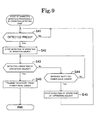
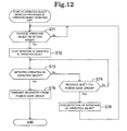
- Figs. 9 to 12 are diagrams for describing the operation of the information processing terminal.
- an information processing terminal 51 includes the display part 12, the power supply part 14, a main control part 61, and an operation detecting part 62.
- elements of the information processing terminal 51 shown in Fig. 8 elements corresponding to those of the information processing terminal 1 shown in Fig. 1 are denoted by the same reference numerals. Therefore, the same components will be briefly described.
- the information processing terminal 51 has at least three states: a running state (a first running state) to perform a preset operation; a provisional running state (a second running state) where electric power is more saved than in the running state and it is possible to switch the state to the running state in a shorter time than a time for switching the state from the power save state to the running state; and a power save state (a second electric power setting state) where electric power is more saved than in the provisional running state.
- the provisional running state is, for example, a sleep state to stop supply of electric power to the display part 12, a storage part like a hard disk drive (not shown in the drawings), peripheral equipment, and so on, which are part of the components configuring the information processing terminal 51.
- the power save state is, for example, a suspend state to disconnect at least a main power supply to reduce power consumption than in the provisional running state.
- the power save state is, for example, a state to reduce only the power consumption of the display part 12 (decrease the luminescence, turn off the screen, and disconnect from the power supply) than in the provisional running state where at least part of the display part 12, the operation detecting part 62 and the main control part 61 are operating so that it is possible to quickly respond to an operation by the user.
- the provisional running state and the power save state are not limited to the abovementioned ones. It is enough, for example, as far as the magnitude of the maximum power consumption in the running state is the largest, the magnitude of the maximum power consumption in the provisional running state is the second largest, and the magnitude of the maximum power consumption in the power save state is the third largest (magnitude of maximum power consumption: running state > provisional running state > power save state).
- the main control part 61 has the same configuration as the main control part 11 described above.
- the main control part 61 includes a CPU, a memory, and an input/output interface (not shown in the drawings). Then, the CPU loads a program stored in the memory and the main control part 61 thereby controls the operation of the information processing terminal 51.
- the main control part 61 controls activation of the display part 12 and display to the display part 12.
- the main control part 61 displays various kinds of data such as characters and images on the display face of the display part 12.
- the display part 12 is formed by, for example, a liquid crystal display, an organic EL display, or the like.
- the main control part 61 (a state control part) has a function to switch the state of the information processing terminal 51 among three states (the running state, the provisional running state, and the power save state). For example, when a predetermined input operation has not been accepted by a preset time in the running state, the main control part 61 switches the sate from the running state to the power save state. Further, for example, when a press is detected by the press detecting part 21 of the operation detecting part 62 in the power save state, the main control part 61 switches the state from the power save state to the provisional running state.
- the main control part 61 switches the state from the provisional running state to the running state. Besides, when, after switching of the state to the provisional running state, a recovery-from-power-save order has not been received from the operation object detecting part 71 by a preset standby time, the main control part 61 transmits a shift-to-power-save order to the operation object detecting part 71, and switches the state from the provisional state to the power save state.
- a recovery-from-power-save order is an order for switching the state of the information processing terminal 51 from the provisional running state (or the power save state) to the running state.
- a shift-to-power-save order is an order for shifting the state of the operation object detecting part 71 to the power save state.
- the main control part 61 has a function to monitor detection of a press by the press detecting part 21.
- the function to monitor detection of a press by the press detecting part 21 is the same as the function of the operation object detecting part 22 to monitor detection of a press by the press detecting part 21 described referring to Fig. 3 .
- the main control part 61 can also transmit an operation object detection order for starting detection of an operation object to the operation object detecting part 71, which will be described later, when a press is detected by the press detecting part 21.
- the operation detecting part 62 includes the press detecting part 21, the touchscreen 23, and the operation object detecting part 71.
- the operation detecting part 62 accepts a predetermined input operation, and also detects an operation by a preset operation object.
- the operation detecting part 62 functions as an input interface.
- the press detecting part 21, which is formed on the display face of the display part 12, detects a press on the display face and accepts a pressing operation of pressing the display face as an input operation. Because the press detecting part 21 detects a press on the display face even in the power save state, the press detecting part 21 is electrically connected with the power supply part 14 and is kept running at all times.
- the operation object detecting part 71 has a function to detect an operation by a preset operation object. Moreover, the operation object detecting part 71 has a function to monitor detection of a press by the press detecting part 21. In the power save state, the operation object detecting part 71 is in a state where only the function to monitor detection of a press by the press detecting part 21 works and the function to detect an operation by an operation object stops (the power save state of the operation object detecting part 71). The operation object detecting part 71 may not have the function to monitor detection of a press by the press detecting part 21.
- the operation object detecting part 71 when receiving an operation object detection order transmitted from the main control part 61, the operation object detecting part 71 starts electrical connection with the power supply part 14 and activates the function to detect an operation by an operation object. Consequently, the operation object detecting part 71 recovers from the power save state, and starts detection of an operation by an operation object by using the touchscreen 23.
- the touchscreen 23 is, for example, a capacitive touchscreen, and is formed on the display face of the display part 12.
- the operation object detecting part 71 detects a contact operation by an operation object which can be detected by the touchscreen 23 and which has a characteristic of permitting the flow of electrical current (e.g., a human body, and a conductor).
- the operation object detecting part 71 transmits, to the main control part 61, a recovery-from-power-save order for switching the state of the information processing terminal 51 (the components configuring the information processing terminal 51) from the provisional running state to the running state.
- the operation object detecting part 71 stops detection of an operation object, and returns to the power save state before the detection of the press by the press detecting part 21.
- the operation object detecting part 71 may be configured to, in a case where a press is detected by the press detecting part 21, detection of an operation by an operation object is started, and a preset standby time passes by without detection of an operation by an operation object, stop detection of an operation object and return to the power save state before detection of the press by the press detecting part 21.
- the press detecting part 21 determines whether or not it has detected a press on the display face. In a case where the press detecting part 21 determines at step S41 that it has not detected a press (step S41: No), the processing returns to step S41 and the same process is repeated. On the other hand, in a case where the press detecting part 21 determines at step S41 that it has detected a press on the display face (step S41: Yes), at step S42, the operation object detecting part 71 starts detection of an operation by an operation object. In other words, the operation object detecting part 71 activates the touchscreen 23 and the function of the operation object detecting part 71 to detect an operation by an operation object, and recovers from the power save state.
- the operation object detecting part 71 determines whether or not it has detected an operation by an operation object. In a case where the operation object detecting part 71 determines at step S43 that it has not detected an operation by an operation object (step S43: No), at step S44, the operation object detecting part 71 determines whether or not it has received a shift-to-power-save order from the main control part 61. In a case where the operation object detecting part 71 determines at step S44 that it has not received a shift-to-power-save order (step S44: No), the processing returns to step S43 and the processes therefrom are repeated.
- step S51 the main control part 61 determines (monitors) whether or not a press has been detected by the press detecting part 21. In a case where the main control part 61 determines at step S51 that a press has not been detected (step S51: No), the processing returns to step S51 and the same process is repeated. On the other hand, in a case where the main control part 61 determines at step S51 that a press has been detected (step S51: Yes), at step S52, the main control part 61 switches the state from the power save state to the provisional running state. By switching the state to the provisional running state, the main control part 61 can switch the state to the running state in a shorter time than a time for switching the state of the information processing terminal 51 from the power save state to the running state.
- step S53 the main control part 61 determines whether or not it has received a recovery-from-power-save order from the operation object detecting part 71. In a case where the main control part 61 determines at step S53 that it has not received a recovery-from-power-save order (step S53: No), at step S54, the main control part 61 determines whether or not a preset standby time has passed by after switching the state to the provisional running state. In a case where the main control part 61 determines at step S54 that the preset standby time has not passed by (step S54: No), the processing returns to step S53 and the processes therefrom are repeated.
- step S55 the main control part 61 transmits a shift-to-power-save order to the operation object detecting part 71.
- step S56 the main control part 61 switches the state from the provisional running state to the power save state.
- step S45 the operation object detecting part 71 stops detection of an operation by an operation object.
- the operation object detecting part 71 stops the touchscreen 23 and the function of the operation object detecting part 71 to detect an operation by an operation object, and returns to the power save state.
- step S46 the operation object detecting part 71 transmits a recovery-from-power-save order to the main control part 61. Consequently, it is possible to shift the state of the information processing terminal 51 to the running state. After the process at step S46 is executed, the operation detection processing 2 ends.
- step S57 the main control part 61 switches the state from the provisional running state to the running state. Consequently, electric power is supplied to each of the components configuring the information processing terminal 51, and the information processing terminal 51 operates.
- the main control part 61 switches the state of the information processing terminal 51 from the power save state to the provisional running state where it is possible to switch the state to the running state in a shorter time than a time for switching the state from the power save state to the running state.
- the state is switched from the provisional running state to the running state, with the result that it is possible to more quickly recover the information processing terminal from the power save state.
- both the main control part 61 and the operation object detecting part 71 monitor the result of detection by the press detecting part 21, but it is also possible to cause either the main control part 61 or the operation object detecting part 21 (e.g., the main control part 61) to monitor the result of detection by the press detecting part 21.
- the main control part 61 or the operation object detecting part 21 e.g., the main control part 61
- FIGs. 11 and 12 another operation of the information processing terminal 51 will be described in detail.
- step S61 the main control part 61 determines (monitors) whether or not a press has been detected by the press detecting part 21. In a case where the main control part 61 determines at step S61 that a press has not been detected (step S61: No), the processing returns to step S61 and the same process is repeated. On the other hand, in a case where the main control part 61 determines at step S61 that a press has been detected (step S61: Yes), at step S62, the main control part 61 switches the state from the power save state to the provisional running state. Next, at step S63, the main control part 61 transmits an operation object detection order for causing the operation object detecting part 71 to start detection of an operation object, to the operation object detecting part 71.
- step S71 in Fig. 12 the operation object detecting part 71 determines whether or not it has received the operation object detection order transmitted in the process at step S63 in Fig. 11 .
- step S71: No the processing returns to step S71 and the same process is repeated.
- step S71: Yes the operation object detecting part 71 starts detection of an operation by an operation object.
- the operation object detecting part 71 activates the touchscreen 23 and the function of the operation object detecting part 71 to detect an operation by an operation object, and recovers from the power save state.
- the operation object detecting part 71 determines whether or not it has detected an operation by an operation object. In a case where the operation object detecting part 71 determines at step S73 that it has not detected an operation by an operation object (step S73: No), at step S74, the operation object detecting part 71 determines whether or not it has received a shift-to-power-save order from the main control part 61. In a case where the operation object detecting part 71 determines at step S74 that it has not received a shift-to-power-save order (step S74: No), the processing returns to step S73 and the processes therefrom are repeated.
- the main control part 61 determines whether or not it has received a recovery-from-power-save order from the operation object detecting part 71. In a case where the main control part 61 determines at step S64 that it has not received a recovery-from-power-save order (step S64: No), at step S65, the main control part 61 determines whether or not a preset standby time has passed by since switching to the provisional running state.
- step S65 determines at step S65 that the standby time has not passed by (step S65: No)
- step S65: Yes the main control part 61 transmits a shift-to-power-save order to the operation object detecting part 71.
- step S67 the main control part 61 switches the state from the provisional running state to the power save state. After the process at step S67, the processing returns to step S61 and the processes therefrom are repeated.
- step S75 the operation object detecting part 71 stops detection of an operation by an operation object.
- the operation object detecting part 71 stops the touchscreen 23 and the function of the operation object detecting part 71 to detect an operation by an operation object, and returns to the power save state.
- the processing returns to step S71 and the processes therefrom are repeated.
- step S76 the operation object detecting part 71 transmits a recovery-from-power-save order to the main control part 61. After the process at step S76 is executed, the operation object detection processing ends.
- step S68 the main control part 61 switches the state from the provisional running state to the running state.
- the main control part 61 switches the state from the power save state to the provisional running state where it is possible to switch to the running state in a shorter time than a time for switching the state from the power save state to the running state. Then, because the main control part 61 transmits an operation object detection order to the operation object detecting part 71, the operation object detecting part 71 does not need to monitor detection of a press by the press detecting part 21, it is possible to reduce the cost, and it is also possible to start the processing by the operation object detecting part 71 more securely.
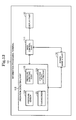
- Fig. 13 is a diagram for describing the configuration of an information processing terminal.
- Fig. 14 is a diagram for describing the operation of the information processing terminal.
- an information processing terminal 101 includes a main control part 111, the display part 12, the power supply part 14, and an operation detecting part 112.
- the information processing terminal 101 has at least two states: a running state to perform a preset operation; and a power save state which is more power-save setting (less power-consuming) than the running state.
- the power save state is, for example, a sleep state to stop supply of electric power to the display part 12, a storage part like a hard disk drive (not shown in the drawings), peripheral equipment, and so on, which are part of the components configuring the information processing terminal 101, or a suspend state to disconnect at least a main power supply to reduce power consumption than in the sleep state.
- the power save state (a second electric power setting state) can be any state as far as power consumption is reduced than in the running state (a first electric power setting state).
- the main control part 111 includes a CPU, a memory, and an input/output interface (not shown in the drawings). Then, the CPU loads a program stored in the memory and the main control part 111 thereby controls the operation of the information processing terminal 101.
- the main control part 111 controls activation of the display part 12 and display to the display part 12.
- the main control part 111 displays various kinds of data such as characters and images on the display face of the display part 12.
- the display part 12 is configured by, for example, a liquid crystal display, an organic EL display, or the like. Meanwhile, the display part 12 is not limited to the abovementioned configuration, and may be realized by any configuration.
- the main control part 111 (a state control part) has a function to switch the state of the information processing terminal 101 between the two states (the running state and the power save state). For example, when a predetermined input operation is not accepted by a preset time in the running state, the main control part 111 switches the state from the running state to the power save state. Moreover, for example, when a predetermined input operation satisfying a preset condition is accepted in the power save state, the main control part 111 switches the state from the power save state to the running state.
- the operation detecting part 112 includes the operation object detecting part 22, the touchscreen 23, a pressure sensor 121, and a pressure detecting part 122.
- the operation detecting part 112 detects an input operation by a preset operation object.
- the operation detecting part 112 functions as an input interface.
- the pressure sensor 121 is formed on the display face of the display part 12, and is configured to be capable of detecting the pressure of an operation object onto the display face.
- the pressure detecting part 122 detects the pressure of an operation object onto the display face by using the pressure sensor 121. Then, the pressure detecting part 122 determines whether or not the magnitude of the detected pressure is equal to or more than a preset threshold (whether or not it is equivalent to a press on the display face). Because the pressure detecting part 122 detects the pressure of an operation object onto the display face even in the power save state, the pressure detecting part 122 is electrically connected with the power supply part 14 and kept running at all times. It is assumed that the power consumption of the pressure detecting part 122 is sufficiently smaller than the power consumption of the operation object detecting part 22. Moreover, the magnitude of the threshold can be changed by input when necessary.
- the operation object detecting part 123 has a function to detect an operation by a preset operation object. Moreover, the operation object detecting part 123 has a function to monitor detection of pressure of the magnitude of the preset threshold or more by the pressure detecting part 122. In the power save state, the operation object detecting part 123 is in a state where only the function to monitor detection of a press by the press detecting part 21 works and the function to detect an operation by an operation object stops (the power save state of the operation object detecting part 123).
- the operation object detecting part 123 When a press is detected by the pressure detecting part 122, the operation object detecting part 123 is provided with supply of larger electric power than in the power save state from the power supply part 14, and activates the function to detect an operation by an operation object and the touchscreen 23. Consequently, the operation object detecting part 123 recovers from the power save state and starts detection of an operation object by using the touchscreen 23.
- the touchscreen 23 is, for example, a capacitive touchscreen, and is formed on the display face of the display part 12.
- the operation object detecting part 123 detects an operation object which can be detected by the touchscreen 23 and which has a characteristic of permitting the flow of electrical current (e.g., a human body, and a conductor). Meanwhile, the touchscreen 23 is not limited to a capacitive type, and may be any configuration that can detect a preset operation object.
- the operation object detecting part 123 When detecting an operation by an operation object by using the touchscreen 23, the operation object detecting part 123 transmits, to the main control part 111, a recovery-from-power-save order for switching the information processing terminal 101 from the power save state to the running state.
- the operation object detecting part 123 stops detection of an operation object and returns to the power save state before the detection of the pressure of the magnitude of the threshold or more by the pressure detecting part 122.
- the operation object detecting part 123 may not have the function to monitor detection of pressure of the magnitude of the threshold or more by the pressure detecting part 122.
- the pressure detecting part 122 transmits an operation object detection order to the operation object detecting part 123 in the case of detecting pressure of the magnitude of the threshold or more.
- the operation object detecting part 123 starts electrical connection with the power supply part 14 and activates the function to detect an operation by an operation object and the touchscreen 23. Consequently, the operation object detecting part 123 recovers from the power save state and starts detection of an operation object by using the touchscreen 23.
- Fig. 14 the operation of the abovementioned information processing terminal 101 will be described in detail. Because the operation of the main control part 111 is the same as the operation of the main control part 11 shown in Fig. 6 , the description will be made referring to Fig. 6 . Moreover, in the example shown by Fig. 14 , it is assumed that the information processing terminal 101 is set to the power save state.
- the pressure detecting part 122 determines whether or not it has detected pressure of the magnitude of a preset threshold or more. In a case where the pressure detecting part 122 determines at step S91 that it has not detected pressure of the magnitude of the threshold or more (step S91: No), the processing returns to step S91 and the same process is repeated. On the other hand, in a case where the pressure detecting part 122 determines at step S91 that it has detected pressure of the magnitude of the threshold or more (step S91: Yes), at step S92, the operation object detecting part 123 starts detection of an operation by an operation object. In other words, the operation object detecting part 123 activates the touchscreen 23 and the function of the operation object detecting part 123 to detect an operation by an operation object, and recovers from the power save state.
- the operation object detecting part 123 determines whether or not it has detected an operation by an operation object.
- the operation object detecting part 123 determines whether or not an object having applied the pressure on the display face in the process at step S91 is a preset operation object (e.g., a human body).
- the operation object detecting part 123 determines at step S93 that it has not detected an operation by an operation object (step S93: No)
- the operation object detecting part 123 determines whether or not a preset standby time has passed by since the detection of the pressure of the magnitude of the threshold or more by the pressure detecting part 122.
- step S94 determines at step S94 that the standby time has not passed by (step S94: No)
- step S94 determines at step S94 that the standby time has not passed by (step S94: No)
- step S95 the operation object detecting part 123 stops detection of an operation by an operation object.
- the operation object detecting part 123 stops the touchscreen 23 and the function of the operation object detecting part 123 to detect an operation by an operation object, and returns to the power save state.
- the processing returns to step S91 and the processes therefrom are repeated.
- step S93 determines at step S93 that it has detected an operation by an operation object (step S93: Yes)
- step S96 the operation object detecting part 123 transmits a recovery-from-power-save to the main control part 111. After the process at step S93 is executed, operation detection processing 3 ends.
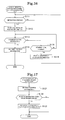
- the main control part 111 receives the recovery-from-power-save order transmitted in the process at step S96 in Fig. 14 . Then, at step S12, the main control part 111 switches the state from the power save state to the running state.
- the pressure detecting part 122 determines whether or not it has detected pressure of a preset threshold or more, so that it is possible to set the definition of a press (a threshold to detect a press) in more detail as compared with a case of using the press detecting part 21 configured by a switch and it is possible to increase the convenience for the user.
- the information processing terminal 101 can be configured to switch among the running state, the provisional running state and the power save state by employment of the configuration described in the second exemplary embodiment.
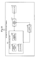
- Fig. 15 is a diagram for describing the configuration of an information processing terminal.
- Figs. 16 and 17 are diagrams for describing the operation of the information processing terminal.
- an information processing terminal 201 includes the display part 12, the power supply part 14, a main control part 211, and an operation detecting part 212.
- elements corresponding to those of the information processing terminal 1 shown in Fig. 1 are denoted by the same reference numerals.
- the information processing terminal 201 is different from the information processing terminal 1 in that the information processing terminal 201 acquires position information by an input operation instead of detecting an operation by an operation object, whereas the other components are the same as those of the information processing terminal 1. Therefore, the same components will be briefly described.
- the information processing terminal 201 has at least two states: a running state to perform a preset operation; and a power save state to be more power-save setting (i.e., less power-consuming) than the running state.
- the power save state is, for example, a sleep state to stop supply of electric power to the display part 12, a storage part like a hard disk drive (not shown in the drawings), peripheral equipment, and so on, which are part of the components configuring the information processing terminal 201, or a suspend state to disconnect at least a main power supply to reduce power consumption than in the sleep state.
- the power save state (a second electric power setting state) can be any state as far as power consumption is less than in the running state (a first electric power setting state) as described in the first exemplary embodiment.
- the main control part 211 includes a CPU, a memory, and an input/output interface (not shown in the drawings). Then, the CPU loads a program stored in the memory and the main control part 211 thereby controls the operation of the information processing terminal 201.
- the main control part 211 controls activation of the display part 12 and display to the display part 12.
- the main control part 211 displays various kinds of data such as characters and images on the display face of the display part 12.
- the display part 12 is configured by, for example, a liquid crystal display, an organic EL display, or the like. Meanwhile, the display part 12 is not limited to the abovementioned configuration, and may be realized by any configuration.
- the main control part 211 (a state control part) has a function to switch the state of the information processing terminal 201 between the two states (the running state and the power save state). For example, when a predetermined input operation is not accepted by a preset time in the running state, the main control part 211 switches the state from the running state to the power save state. Moreover, for example, when a predetermined input operation satisfying a preset condition is accepted in the power save state, the main control part 211 switches the state from the power save state to the running state.
- the operation detecting part 212 includes the press detecting part 21, the touchscreen 23, and a position information acquiring part 221.
- the operation detecting part 212 accepts a predetermined input operation, and also acquires position information of the display face regarding the predetermined input operation.
- the operation detecting part 212 functions as an input interface.
- the press detecting part 21 is formed on the display face of the display part 12, and detects a press on the display face. Because the press detecting part 21 detects a press on the display face even in the power save state, the press detecting part 21 is electrically connected with the power supply part 14 and is kept running at all times.
- the position information acquiring part 221 (a position information acquiring part) has a function to, by using the touchscreen 23, acquire position information of a region in which contact is detected. Moreover, the position information acquiring part 221 has a function to monitor detection of a press by the press detecting part 21. Then, the position information acquiring part 221 transmits the acquired position information to the main control part 211. In the power save state, the position information acquiring part 221 is in a state where only the function to monitor detection of a press by the press detecting part 21 works and the function to, by using the touchscreen 23, acquire position information of a region where contact is detected stops (the power save state of the position information acquiring part 221). The function of the position information acquiring part 221 to monitor detection of a press by the press detecting part 21 is the same as the function of the operation object detecting part 22 described above referring to Fig. 3 .
- the position information acquiring part 221 is provided with supply of larger electric power than in the power save state from the power supply part 14, and activates the function to acquire position information of a region where contact has been detected and the touchscreen 23. Consequently, the position information acquiring part 221 recovers from the power save state, and starts acquisition of position information of a region where contact has been detected by using the touchscreen 23.
- the position information acquiring part 221 is not limited to using the touchscreen 23, and can acquire position information by using a device, such as a resistive touchscreen and a matrix touchscreen with pressing switches arranged in matrix, which has a configuration capable of detecting position information.
- the touchscreen 23 is, for example, a capacitive touchscreen, and is formed on the display face of the display part 12. Meanwhile, the touchscreen 23 does not need to be formed on the entire display face of the display part 12, and may be formed in a partial region of the display face. Moreover, a plurality of touchscreens 23 may be formed on the display face. Furthermore, the touchscreen 23 is not limited to a capacitive type, and may be any configuration that can detect position information of the contact display face.
- the position information acquiring part 221 transmits the acquired position information to the main control part 211.
- the position information acquiring part 221 stops acquisition of position information and returns to the power save state before detection of a press by the press detecting part 21.
- the main control part 211 When receiving the position information transmitted from the position information acquiring part 221, the main control part 211 determines whether or not the received position information is within a preset region of the display face. Then, in a case where the position information is within the preset region, the main control part 211 switches the state from the power save state to the running state. On the other hand, in a case where the position information is not within the preset region, the main control part 211 does not switch the state (keeps the power save state).
- the press detecting part 21 determines whether or not it has detected a press on the display face. In a case where the press detecting part 21 determines at step S111 that it has not detected a press (step S111: No), the processing returns to step S111 and the same process is repeated. On the other hand, in a case where the press detecting part 21 determines at step S111 that it has detected a press (step S111: Yes), at step S 112, the position information acquiring part 221 starts acquisition of position information. In other words, the position information acquiring part 221 activates the touchscreen 23 and the function of the position information acquiring part 221 to acquire position information, and recovers from the power save state.
- step S 113 the position information acquiring part 221 determines whether or not it has acquired position information. In a case where the position information acquiring part 221 determines at step S 113 that it has not acquired position information (step S113: No), at step S 114, the position information acquiring part 221 determines whether or not a preset standby time has passed by since the detection of the press by the press detecting part 21. In a case where the position information acquiring part 221 determines at step S 114 that the standby time has not passed by (step S 114: No), the processing returns to step S113 and the processes therefrom are repeated.
- step S115 the position information acquiring part 221 stops acquisition of position information.
- the position information acquiring part 221 stops the touchscreen 23 and the function of the position information acquiring part 221 to acquire position information, and then returns to the power save state.
- the processing returns to step S111 and the processes therefrom are repeated.
- step S116 the position information acquiring part 221 transmits a recovery-from-power-save order to the main control part 211. After the process at step S116 is executed, operation detection processing 4 ends.
- the main control part 211 receives the position information transmitted in the process at step S113 in Fig. 16 . Then, at step S122, the main control part 211 determines whether or not the position information is within a predetermined range set in advance. To be specific, the main control part 211 determines whether or not the position information is within the range of a preset region of the display face of the display part 12. In a case where the main control part 211 determines at step S122 that the position information is within the preset range (step S122: Yes), at step S123, the main control part 211 switches the state from the power save state to the running state.
- step S123 After the process at step S123 is executed, and in a case where the main control part 211 determines at step S122 that the position information is not within the preset range (step S122: No), state control processing 4 ends.
- the information processing terminal 201 activates the position information acquiring part 221 (and the touchscreen 23) and, when position information is acquired by the position information acquiring part 221, the information processing terminal 201 causes the main control part 211 to switch the state from the power save state to the running state. Because thus recovering from the power save state stepwise, it is possible to achieve reduction of the power consumption of the information processing terminal.
- the position information acquiring part 221 can be provided.
- the main control part 61 of the information processing terminal 51 in the second exemplary embodiment can be configured to switch the state of the information processing terminal 51 based on position information acquired by the position information acquiring part 221.
- the main control part 61 switches the state from the power save state to the provisional running state.
- the main control part 61 switches the state from the provisional running state to the running state.
- the main control part 61 transmits a shift-to-power save order to the position information acquiring part 221. Then, in the case of receiving the shift-to-power-save order transmitted from the main control part 61, the position information acquiring part 221 stops acquisition of position information and returns to the power save state before detection of the press by the press detecting part 21.
- the information processing terminal may not switch to the same power save state as the original one.
- the information processing terminal may shift stepwise to the original power save state through two or more states, or may keep in a different power save state.
- the main control part (the main control parts 11, 61, 111 and 211) may switch the state to the first power save state. Moreover, after switching the state to the first power save state, the main control part may switch the state to the second power save state when a preset time passes by.
- An information processing terminal comprising:
- the information processing terminal 1 switches from the second power setting state to the first power setting state based on the results of detection by the press detecting part 21 and the operation object detecting part 22. Therefore, it is possible to prevent the second power setting state from being terminated by a wrong operation and achieve reduction of the power consumption of the information processing terminal.
- the information processing terminal according to Supplementary Note 1, wherein the input operation accepting part is formed on a display face of a display part of the information processing terminal and configured to accept, as the input operation, a pressing operation to press the display face.
- the information processing terminal according to Supplementary Note 1 or 2, wherein the operation object detecting part is configured to, by using a touchscreen, detect an operation by the operation object with a characteristic of permitting flow of electricity, the touchscreen being formed on a display face of a display part of the information processing terminal and being capable of detecting an operation by the operation object by capacitive technology.
- an operation by an operation object having a characteristic of permitting the flow of electricity is detected by a capacitive touchscreen formed on the display face of the display part of the information processing terminal. Therefore, it is possible to prevent that the state is switched from the power save state to the normal running state in an operation by an object that is not intended by the user, and it is possible to achieve reduction of the power consumption of the information processing terminal.
- the operation object detecting part is configured to stop detection of an operation by the operation object when the state is the second power setting state, and start detection of an operation by the operation object when the input operation is accepted by the input operation accepting part in the second power setting state.
- detection of an operation by an operation object is stopped when the state is the power save state, and detection of an operation by an operation object is started when an input operation is accepted in the power save state. Therefore, it is possible to achieve reduction of the power consumption of the information processing terminal in the power save state.
- the operation object detecting part is configured to stop detection of an operation by the operation object in a case where, after the input operation is accepted by the input operation accepting part in the second power setting state and detection of an operation by the operation object is started, a preset time passes by without detection of an operation by the operation object.
- the state controlling means is configured not to switch the state to the first power setting state in a case where, in the second power setting state, the input operation is accepted by the input operation accepting part and also an operation by the operation object is not detected by the operation object detecting part.
- the information processing terminal 1 switches from the power save state to the running state based on the results of detection by the press detecting part 21 and the operation object detecting part 22. Therefore, it is possible to prevent the power save state from being terminated by a wrong operation and achieve reduction of the power consumption of the information processing terminal.
- the state when the state is returned to the power save state, the state is switched to a different power save state (the first power save state) from a power save state before the switching (the second power save state). Therefore, it is possible to speedily recover the state from the power save state while realizing power saving of the information processing terminal.
- the state controlling means is configured to switch the state from the first power save state to the second power save state when a preset time passes by after the state is switched to the first power save state.
- the state is gradually changed to power saving by switching the power save states stepwise. Therefore, it is possible to speedily recover the state from the power save state while realizing power saving of the information processing terminal.
- the information processing terminal is switched from the second running state to the first running state after switched from the power save state to the second running state. Therefore, when an operation object is detected by the operation object detecting part, it is possible to cause the information processing terminal to more speedily operate, and it is possible to increase the convenience for the user.
- the information processing terminal according to any of Supplementary Notes 1 to 13, wherein the operation object detecting part is configured to detect a human body as the operation object.
- An information processing terminal comprising:
- the state controlling means is configured to switch the state from the power save state to the running state in a case where, in the power save state, the input operation is accepted by the input operation accepting part and also position information acquired by the position information acquiring part is included within a preset region of a display face of a display part of the information processing terminal.
- An information processing method by an information processing terminal comprising:
- the information processing method comprising accepting a pressing operation to press a display face of a display part of the information processing terminal, as the input operation.
- a computer program comprising instructions for causing an information processing terminal, which includes an input operation accepting part configured to accept a predetermined input operation and an operation object detecting part configured to detect an operation by a preset operation object, to realize a state controlling means for controlling switching of a state of the information processing terminal between a first power setting state and a second power setting state, the second power setting state being a more power save setting than the first power setting state, wherein the state controlling means is configured to switch the state from the second power setting state to the first power setting state when, in the second power setting state, the input operation is accepted by the input operation accepting part and also an operation by the operation object is detected by the operation object detecting part.
Landscapes
- Engineering & Computer Science (AREA)
- Theoretical Computer Science (AREA)
- Physics & Mathematics (AREA)
- General Engineering & Computer Science (AREA)
- General Physics & Mathematics (AREA)
- Computer Networks & Wireless Communication (AREA)
- Signal Processing (AREA)
- Power Sources (AREA)
- Telephone Function (AREA)
- User Interface Of Digital Computer (AREA)
Abstract
Description
- The present invention relates to an information processing terminal. More specifically, the present invention relates to an information processing terminal which has a power save function to reduce power consumption.
- In recent years, mobile information processing terminals such as a mobile phone and a tablet PC (Personal Computer) have become capable of realizing various kinds of processing. Such information processing terminals often use a battery as a power supply, and the operation time of information processing terminals may become shorter due to increase of power consumption. Thus, techniques to reduce the power consumption of information processing terminals have been developed.
- In one example of the techniques, in a case where an operation on an information processing terminal has not been conducted for a given time, the state is switched to a power save state where power consumption is less than in a normal running state, and, in a case where an operation on the information processing terminal is conducted in the power save state, the state is switched from the power save state to the running state (e.g., see Patent Document 1).
- Patent Document 1: Japanese Unexamined Patent Application Publication No.
2005-202742 - However, in the abovementioned technique, the state may switch from the power save state to the running state at the timing that is against the user's intention. For example, when the user carries an information processing terminal in a bag or the like, and the information processing terminal is brought to a state where an operation is conducted thereon because the information processing terminal comes in contact with another object in the bag, the state may switch from the power save state to the running state. Therefore, there is a problem that reduction of the power consumption of an information processing terminal cannot be achieved.
- Accordingly, an object of the present invention is to provide an information processing terminal which can solve the problem that reduction of the power consumption of an information processing terminal cannot be achieved.
- In order to achieve the object, an information processing terminal as an aspect of the present invention includes:
- a state controlling means for controlling switching of a state of the information processing terminal between a first power setting state and a second power setting state, the second power setting state being a more power save setting than the first power setting state;
- an input operation accepting part configured to accept a predetermined input operation; and
- an operation object detecting part configured to detect an operation by a preset operation object.
- The state controlling means is configured to switch the state from the second power setting state to the first power setting state when, in the second power setting state, the input operation is accepted by the input operation accepting part and also an operation by the operation object is detected by the operation object detecting part.
- Further, an information processing method as another aspect of the present invention is a method by an information processing terminal, and the information processing method includes:
- accepting a predetermined input operation:
- detecting an operation by a preset operation object; and
- switching a state of the information processing terminal from a second power setting state to a first power setting state in a case where, in the second power setting state, the input operation is accepted and also an operation by the operation object is detected, the second power setting state being a more power save setting than the first power setting state.
- Further, a program as another aspect of the present invention is a computer program including instructions for causing an information processing terminal, which includes an input operation accepting part configured to accept a predetermined input operation and an operation object detecting part configured to detect an operation by a preset operation object, to realize a state controlling means for controlling switching of a state of the information processing terminal between a first power setting state and a second power setting state, the second power setting state being a more power save setting than the first power setting state.
- The state controlling means is configured to switch the state from the second power setting state to the first power setting state when, in the second power setting state, the input operation is accepted by the input operation accepting part and also an operation by the operation object is detected by the operation object detecting part.
- The present invention has a beneficial effect that it is possible to achieve reduction of the power consumption of an information processing terminal with the configurations as described above.
-
-
Fig. 1 is a block diagram showing the outline of the configuration of an information processing terminal according to a first exemplary embodiment of the present invention; -
Figs. 2A and 2B are diagrams for describing the outline of the information processing terminal; -
Fig. 3 is a circuit diagram for describing the configuration of the information processing terminal; -
Fig. 4 is a block diagram showing the outline of another configuration of the information processing terminal; -
Fig. 5 is a flowchart showing the operation of an operation detecting part; -
Fig. 6 is a flowchart showing the operation of a main control part; -
Fig. 7 is a flowchart showing the operation of the operation detecting part; -
Fig. 8 is a block diagram showing the outline of the configuration of an information processing terminal according to a second exemplary embodiment of the present invention; -
Fig. 9 is a flowchart showing the operation of an operation detecting part; -
Fig. 10 is a flowchart showing the operation of a main control part; -
Fig. 11 is a flowchart showing the operation of the main control part; -
Fig. 12 is a flowchart showing the operation of an operation object detecting part; -
Fig. 13 is a block diagram showing the outline of the configuration of an information processing terminal according to a third exemplary embodiment of the present invention; -
Fig. 14 is a flowchart showing the operation of an operation detecting part; -
Fig. 15 is a block diagram showing the outline of the configuration of an information processing terminal according to a fourth exemplary embodiment of the present invention; -
Fig. 16 is a flowchart showing the operation of an operation detecting part; and -
Fig. 17 is a flowchart showing the operation of a main control part. - A first exemplary embodiment of the present invention will be described referring to
Figs. 1 to 6 .Figs. 1 to 4 are diagrams for describing the configuration of an information processing terminal.Figs. 5 and 6 are diagrams for describing the operation of the information processing terminal. - As shown in
Fig. 1 , aninformation processing terminal 1 according to this exemplary embodiment includes amain control part 11, adisplay part 12, anoperation detecting part 13, and apower supply part 14. Moreover, theinformation processing terminal 1 includes components (not shown in the drawings), such as a storage part and a communication part, configuring theinformation processing terminal 1. The components are not limited to the abovementioned ones. For example, thedisplay part 12 and so on can also be the components configuring theinformation processing terminal 1. Theinformation processing terminal 1 is, for example, a smartphone, a tablet PC or the like that are mobile. Theinformation processing terminal 1 has at least two states: a running state (a first electric power setting state of the information processing terminal 1) to perform a preset operation; and a power save state (a second electric power setting state) where power consumption is set to less than operation-time electric power (the maximum power consumption assumed in the running state). - The running state is a state where preset electric power is supplied to each of the components configuring the
information processing terminal 1. The power save state is a state where smaller electric power than the maximum power consumption assumed in the running state is supplied to each of the components configuring theinformation processing terminal 1. The power save state is, for example: a sleep state where supply of electric power to thedisplay part 12, a storage part (not shown in the drawings) like a hard disk drive, peripheral equipment and so on, which are part of the components configuring theinformation processing terminal 1, is stopped; and a suspend state where at least a main power supply is disconnected to make power consumption less than in the sleep state (i.e., a power save setting state). Moreover, the power save state can include, for example, a state where the power consumption of the components is reduced, such as luminance of thedisplay part 12 as the component is reduced (electric power supplied to the display part is made to be less than electric power supplied to the display part in the running state) and display is turned off (supply of electric power to the display part is stopped). The power save state is not limited to the abovementioned one, and may be any state as far as power consumption is made to be less than in the running state. - Further, in the example described above, the first electric power setting state is the running state, and the power save state as the second electric power setting state is the sleep state and the suspend state, but the first and second electric power setting states are not limited to the abovementioned ones and can be any setting states as far as the second electric power setting state is a state where less electric power than the maximum power consumption in the first electric power setting state is supplied (i.e., the power save setting state). For example, the first electric power setting state and the second electric power setting state may be the sleep state and the suspend state, respectively.
- Each of the components has a power save control part for reducing the power consumption of the component. For example, the power save control part of the storage part such as a HDD (Hard Disk Drive) spontaneously stops rotation of the disk to shift to the power save state (the power save state of the storage part) (i.e., execute power save control) in a case where there has not been access for a preset time, and starts rotation of the disk to shift to the running state (the running state of the storage part) (i.e., execute power save recovery) in a case where there is access. Thus, in the running state, the power consumption of the
information processing terminal 1 may become equal to or less than preset maximum power consumption due to power save control by the components. Therefore, depending on the value of the maximum power consumption of each of the components and power save control by each of the components, theinformation processing terminal 1 may not be necessarily in a state where power consumption is larger in the first electric power setting state than in the second electric power setting state (first electric power setting state > second electric power setting state). However, this exemplary embodiment will be described assuming an effect of power save control by the components is small. When an effect of power save control by the components is small, the magnitude of electric power supplied in each of the power setting states (i.e., the setting of electric power) can be considered as the magnitude of the actual power consumption of the components operating in each of the power setting states. - Next, the configuration of the
main control part 11 will be described. Themain control part 11 includes a CPU, a memory, and an input/output interface (not shown in the drawings). Then, the CPU loads a program stored in the memory and themain control part 11 thereby controls the operation of theinformation processing terminal 1. In this exemplary embodiment, functions of themain control part 11 to control the operation of theinformation processing terminal 1 will be described together. However, these functions may be configured by separate function blocks. Moreover, these function blocks do not need to be housed in the same part necessarily. These functions may be configured separately as needed, or may be configured by different parts. - The
main control part 11 controls activation of thedisplay part 12 and display on thedisplay part 12. For example, themain control part 11 displays various kinds of data such as characters and images on the display face of thedisplay part 12. Thedisplay part 12 is formed by, for example, a liquid crystal display, an organic EL (Electroluminescence) display, or the like. Moreover, as shown by examples shown inFigs. 2A and 2B , thedisplay part 12 is placed on the almost entire face on one side of theinformation processing terminal 1 so that a large display region can be secured. Thedisplay part 12 does not need to be the abovementioned configuration necessarily, and may be realized by any configuration. - Further, the main control part 11 (a state controlling means) controls switching between the two states (the running state and the power save state) of the
information processing terminal 1. For example, in a case where a predetermined input operation is not accepted by a preset time in the running state, themain control part 11 switches the state from the running state to the power save state. Moreover, for example, in a case where, in the power save state, a predetermined input operation is accepted by the operation detecting part 13 (a press detecting part 21) and an operation by a preset operation object is detected by the operation detecting part 13 (an operation object detecting part 22), themain control part 11 switches the sate from the power save state to the running state. A predetermined input operation is, for example, a press operation which is pressing the display face of thedisplay part 12. Moreover, an operation by a preset operation object is, for example, a contact operation on the display face by the user's finger (body). The details of theoperation detecting part 13 will be described below. - The
operation detecting part 13 includes thepress detecting part 21, the operationobject detecting part 22, and atouchscreen 23. In the power save state, theoperation detecting part 13 accepts a predetermined input operation, and also detects an operation by a preset operation object. Moreover, in the running state, theoperation detecting part 13 functions as an input interface. - The press detecting part 21 (an input operation accepting part), which is formed on the display face of the
display part 12, detects a press on the display face and accepts a press operation of pressing the display face as an input operation. Because thepress detecting part 21 detects a press on the display face even in the power save state, thepress detecting part 21 is electrically connected with thepower supply part 14 so as to be provided with electric power supply and is kept running at all times. For example, thepress detecting part 21 includes two transparent electrodes which are arranged at a predetermined space. Then, thepress detecting part 21 is formed by a switch which detects mutual contact of the two transparent electrodes and thereby detects a press by an operation object. It is needless to say that thepress detecting part 21 does not need to be formed by a switch necessarily, and may be any one that can detect a press on the display face. - The
press detecting part 21 may be formed on the entire display face of thedisplay part 12, or may be formed on part of the display face. For example, as shown inFig. 2A , theinformation processing terminal 1 may have apress detecting part 21A (a pressing switch) only in a partial region (shown by a dashed line) of the display face of thedisplay part 12. Moreover, for example, as shown inFig. 2B , theinformation processing terminal 1 may have twopress detecting parts display part 12. In this case, when the state of theinformation processing terminal 1 is the power save state, it is enough that at least one (e.g., thepress detecting part 21C) of thepress detecting parts 21 is operating. Further, the number of thepress detecting part 21 is not limited to two, and may be three or more. Furthermore, thepress detecting part 21 may be configured to be capable of detecting a press on the display face in an area other than the display face. For example, thepress detecting part 21 may be configured in a manner that a switch, which is placed between a transparent protection member covering thedisplay part 12 and a casing or placed on the back side of thedisplay part 12, operates to detect a press. - The operation object detecting part 22 (an operation object detecting part) has a function to detect an operation by a preset operation object. An operation by a preset operation object is, for example, a contact operation by an object which can be detected by the
touchscreen 23, and will be described in detail later. Moreover, the operationobject detecting part 22 has a function to monitor detection of a press by thepress detecting part 21. In the power save state, the operationobject detecting part 22 may be in a state where at least the function to monitor detection of a press by thepress detecting part 21 works and the function to detect an operation by an operation object stops (the power save state of the operation object detecting part 22). An example of the function of the operationobject detecting part 22 to monitor detection of a press by thepress detecting part 21 will be described referring toFig. 3 . -
Fig. 3 is a diagram showing the outline of the function to monitor detection of a press by thepress detecting part 21. As shown inFig. 3 , when thepress detecting part 21 configured by a switch is off (disconnected), the operationobject detecting part 22 detects a predetermined driving voltage V supplied from thepower supply part 14. In this state, when thepress detecting part 21 shifts from the off state to an on state (a connected state), the operationobject detecting part 22 is grounded, and therefore, the magnitude of voltage detected by the operationobject detecting part 22 becomes 0. By detecting this voltage change (from the driving voltage V to 0 (GND)), the operationobject detecting part 22 can detect that a predetermined input operation is conducted on the display face of the display part 12 (a press is detected by the press detecting part 21). The function to monitor detection of a press by thepress detecting part 21 is not limited to the example shown inFig. 3 . It is needless to say that a configuration for notifying to the operationobject detecting part 22 that thepress detecting part 21 detects a press may be provided. In this case, the operationobject detecting part 22 has a function to accept notification from thepress detecting part 21, instead of the function to monitor detection of a press by thepress detecting part 21. - The
power supply part 14 may be configured to, when thepress detecting part 21 is on (when thepress detecting part 21 detects a press), change the voltage from the driving voltage V to the voltage 0 during a preset first period. Then, thepower supply part 14 may be configured to, when thepower supply part 14 changes the voltage from 0 to the driving voltage V during a preset second period and the magnitude of voltage detected by the operationobject detecting part 22 is 0 (thepress detecting part 21 is on), change the voltage from the driving voltage V to the voltage 0 again, whereas when thepower supply part 14 changes the voltage from 0 to the driving voltage V and the magnitude of voltage detected by the operationobject detecting part 22 is V (thepress detecting part 21 is off), continue supplying the driving voltage V. Consequently, it is possible to reduce power consumption while a press is detected by thepress detecting part 21. This is applicable to other exemplary embodiments to be described later. - Then, in a case where a press is detected by the
press detecting part 21, the operationobject detecting part 22 recovers from the power save state, and activates the function to detect an operation by an operation object and thetouchscreen 23. Thus, the operationobject detecting part 22 recovers from the power save state, and starts detection of an operation by an operation object by using thetouchscreen 23. - By configuring the
press detecting part 21 by a simple switch, the power consumption of thepress detecting part 21 becomes zero in a not-pressed state. Even in a pressed state, in the case of a press by an operation object which is not previously set, the voltage becomes the driving voltage V. Thus, it is possible to easily reduce power consumption only by simple processing of controlling the driving voltage V, and detect the presence or absence of a press by an operation object. - The
touchscreen 23 is, for example, a capacitive touchscreen, and is formed on the display face of thedisplay part 12. The operationobject detecting part 22 detects a contact operation by an operation object which can be detected by thetouchscreen 23 and which has a characteristic of permitting the flow of electrical current (e.g., a human body, and a conductor). Thetouchscreen 23 is not limited to a capacitive type, and may be any configuration, such as a pen having a coil detecting by electromagnetic induction, that can detect a contact operation by a preset operation object. Moreover, an operation detected by the operationobject detecting part 22 is not limited to a contact operation, and may be a proximity operation by an electromagnetic-induction-type pen, or the like. - Then, upon detecting an operation by an operation object by using the
touchscreen 23, the operationobject detecting part 22 transmits, to themain control part 11, a recovery-from-power-save order for switching theinformation processing terminal 1 from the power save state to the running state. On the other hand, when a press is detected by thepress detecting part 21, detection of an operation by an operation object is started, and thereafter, a preset standby time passes by without detection of an operation by an operation object, the operationobject detecting part 22 stops detection of an operation by an operation object, and returns to the power save state before the press is detected by thepress detecting part 21. - Part of the functions of the operation
object detecting part 22 described above can be realized by another component (function block). For example, as shown by aninformation processing terminal 31 shown inFig. 4 , aninput control part 41 may be added to the configuration of theinformation processing terminal 1, and theinput control part 41 may execute part of the functions of the operationobject detecting part 22. For example, theinput control part 41 determines whether or not a preset standby time has passed by after detection of a press by thepress detecting part 21, and the operationobject detecting part 22 can transmit a recovery-from-power-save order to themain control part 61 when detecting an operation by an operation object before the standby time passes by. Theinput control part 41 can also be applied to other exemplary embodiments to be described later. - To be specific, the
input control part 41 monitors detection of a press by thepress detecting part 21. In the power save state, theinput control part 41 may be in a state where at least the function to monitor detection of a press by thepress detecting part 21 works and the function to detect an operation by an operation object stops (the power save state of the input control part 41). Then, in response to detection of a press by thepress detecting part 21, theinput control part 41 recovers from the power save state. Then, theinput control part 41 determines whether or not a preset standby time has passed by after detection of the press by thepress detecting part 21. Then, in a case where an operation by an operation object has not been detected by the operationobject detecting part 22 before the preset standby time passes by, theinput control part 41 transmits a shift-to-power-save order for switching theoperation detecting part 13 to the power save state, to theoperation detecting part 13. On the other hand, in a case where an operation by an operation object has been detected by the operationobject detecting part 22 before the preset standby time passes by, theinput control part 41 transmits a recovery-from-power-save order for switching theinformation processing terminal 1 from the power save state to the running state, to themain control part 11. Thus, by causing theinput control part 41 to share part of the processing by theoperation detecting part 13, it is possible to efficiently recover the state from the power save state to the running state. - The
input control part 41 is not limited to the above configuration, and may be any configuration that transmits a recovery-from-power-save order to themain control part 11 when a press is detected by thepress detecting part 21 and an operation by an operation object is detected by the operationobject detecting part 22. For example, theinput control part 41 may be configured by a latch circuit or a delay circuit. - Next, referring to
Figs. 5 to 7 , the operation of the abovementionedinformation processing terminal 1 will be described in detail. It is assumed that in the example shown byFigs. 5 to 7 , the state of theinformation processing terminal 1 is set to the power save state. - First, at step S1, the
press detecting part 21 determines whether or not it has detected a press on the display face. In a case where thepress detecting part 21 determines at step S1 that it has not detected a press (step S1: No), the processing returns to step S1 and the same process is repeated. On the other hand, in a case where thepress detecting part 21 determines at step S1 that it has detected a press (step S1: Yes), at step S2, the operationobject detecting part 22 starts detection of an operation by an operation object. In other words, the operationobject detecting part 22 activates thetouchscreen 23 and the function of the operationobject detecting part 22 to detect an operation by an operation object, and recovers from the power save state. - Next, at step S3, the operation
object detecting part 22 determines whether or not it has detected an operation by an operation object. For example, the operationobject detecting part 22 determines whether or not an object having pressed the display face in the process at step S1 is a preset operation object (e.g., a human body). In a case where the operationobject detecting part 22 determines at step S3 that it has not detected an operation by an operation object (step S3: No), at step S4, the operationobject detecting part 22 determines whether or not a preset standby time has passed by since the detection of the press by thepress detecting part 21. In a case where the operationobject detecting part 22 determines at step S4 that the standby time has not passed by yet (step S4: No), the processing returns to step S3 and the processes therefrom are repeated. On the other hand, in a case where the operationobject detecting part 22 determines at step S4 that the standby time has passed by (step S4: Yes), at step S5, the operationobject detecting part 22 stops detection of an operation by an operation object. In other words, the operationobject detecting part 22 stops thetouchscreen 23 and the function of the operationobject detecting part 22 to detect an operation by an operation object, and returns to the power save state. After the process at step S5, the processing returns to step S1 and the processes therefrom are repeated. - On the other hand, in a case where the operation
object detecting part 22 determines at step S3 that it has detected an operation by an operation object (step S3: Yes), at step S6, the operationobject detecting part 22 transmits a recovery-from-power-save order to themain control part 11. After the process at step S6 is executed,operation detection processing 1 ends. - Next, at step S11 in
Fig. 6 , themain control part 11 receives the recovery-from-power-save order transmitted in the process at step S6 inFig. 5 . Then, at step S12, themain control part 11 switches the state from the power save state to the running state. After the process at step S12 is executed, state control processing 1 by themain control part 11 ends. Consequently, electric power is supplied to the respective components configuring theinformation processing terminal 1, and theinformation processing terminal 1 operates. - Thus, the
information processing terminal 1 activates the operation object detecting part 22 (and the touchscreen 23) when a press is detected by thepress detecting part 21, and causes themain control part 11 to switch the state from the power save state to the running state when an operation by an operation object is detected by the operationobject detecting part 22. Therefore, theinformation processing terminal 1 switches from the power save state to the running state based on the results of detection by thepress detecting part 21 and the operationobject detecting part 22, with the result that it is possible to prevent the power save state from being terminated by a wrong operation and achieve reduction of the power consumption of the information processing terminal. - Next, referring to
Fig. 7 , another operation of theinformation processing terminal 1 will be described in detail. In the example shown inFig. 7 , thepress detecting part 21 is formed in a partial region of the display face of thedisplay part 12, and an operation of switching the state from the power save state to the running state when a press is detected by thepress detecting part 21 formed in the partial region of the display face will be described. Theinformation processing terminal 1 is provided with a matrix ofpress detecting part 21 on the display face, so that it can detect a position where an operation object comes in contact. Moreover, because the processing by themain control part 11 is the same as the processing inFig. 6 described above, a description will be made referring toFig. 6 . - First, at step S31, the
press detecting part 21 determines whether or not it has detected a press on the display face. In a case where thepress detecting part 21 determines at step S31 that it has not detected a press (step S31: No), the processing returns to step S31 and the same process is repeated. On the other hand, in a case where thepress detecting part 21 determines at step S31 that it has detected a press (step S31: Yes), at step S32, thepress detecting part 21 determines whether or not a position where the press has been detected is within a preset range. For example, thepress detecting part 21 determines whether or not the region of the operationobject detecting part 21C shown inFig. 2B has been pressed. - In a case where the
press detecting part 21 determines at step S32 that the position where the press has been detected is not within the preset range (step S32: No), the processing returns to step S31 and the processes therefrom are repeated. On the other hand, in a case where thepress detecting part 21 determines at step S32 that the position where the press has been detected is within the preset range (step S32: Yes), the processing proceeds to step S33. - At step S33, the operation
object detecting part 22 starts detection of an operation by an operation object. In other words, the operationobject detecting part 22 activates thetouchscreen 23 and the function of the operationobject detecting part 22 to detect an operation by an operation object, and recovers from the power save state. - Next, at step S34, the operation
object detecting part 22 determines whether or not it has detected an operation by an operation object. In a case where the operationobject detecting part 22 determines at step S34 that it has not detected an operation by an operation object (step S34: No), at step S35, the operationobject detecting part 22 determines whether or not a preset standby time has passed by since the detection of the press by thepress detecting part 21. In a case where the operationobject detecting part 22 determines at step S35 that the standby time has not passed by yet (step S35: No), the processing returns to step S34 and the processes therefrom are repeated. On the other hand, in a case where the operationobject detecting part 22 determines at step S35 that the standby time has passed by (step S35: Yes), at step S36, the operationobject detecting part 22 stops detection of an operation by an operation object. In other words, the operationobject detecting part 22 stops thetouchscreen 23 and the function of the operationobject detecting part 22 to detect an operation by an operation object, and returns to the power save state. After the process at step S36 is executed, the processing returns to step S31 and the processes therefrom are repeated. - On the other hand, in a case where the operation
object detecting part 22 determines at step S34 that it has detected an operation by an operation object (step S34: Yes), at step S37, the operationobject detecting part 22 transmits a recovery-from-power-save order to themain control part 11. After the process at step S37 is executed,operation detection processing 2 ends. - Next, at step S11 in
Fig. 6 , themain control part 11 receives the recovery-from-power-save order transmitted in the process at step S6 inFig. 5 . Then, at step S12, themain control part 11 switches the state from the power save state to the running state. Consequently, electric power is supplied to the respective components configuring theinformation processing terminal 1, and theinformation processing terminal 1 operates. To be specific, the power save state is, for example, a state where supply of electric power to the display part 12 (the component) is stopped and thedisplay part 12 does not display a screen. Moreover, the running state is a state where electric power is supplied to thedisplay part 12 and thedisplay part 12 displays a screen. - Thus, the
information processing terminal 1 activates the operation object detecting part 22 (and the touchscreen 23) when a press is detected by thepress detecting part 21, and causes themain control part 11 to switch the state from the power save state to the running state when an operation by an operation object is detected by the operationobject detecting part 22. Therefore, theinformation processing terminal 1 switches from the power save state to the running state based on the results of detection by thepress detecting part 21 and the operationobject detecting part 22, with the result that it is possible to prevent the power save state from being terminated by a wrong operation and achieve reduction of the power consumption of the information processing terminal. - Next, a second exemplary embodiment of the present invention will be described referring to
Figs. 8 to 12 .Fig. 8 is a diagram for describing the configuration of an information processing terminal.Figs. 9 to 12 are diagrams for describing the operation of the information processing terminal. - As shown in
Fig. 8 , aninformation processing terminal 51 according to this exemplary embodiment includes thedisplay part 12, thepower supply part 14, amain control part 61, and anoperation detecting part 62. Among elements of theinformation processing terminal 51 shown inFig. 8 , elements corresponding to those of theinformation processing terminal 1 shown inFig. 1 are denoted by the same reference numerals. Therefore, the same components will be briefly described. Theinformation processing terminal 51 has at least three states: a running state (a first running state) to perform a preset operation; a provisional running state (a second running state) where electric power is more saved than in the running state and it is possible to switch the state to the running state in a shorter time than a time for switching the state from the power save state to the running state; and a power save state (a second electric power setting state) where electric power is more saved than in the provisional running state. - The provisional running state is, for example, a sleep state to stop supply of electric power to the
display part 12, a storage part like a hard disk drive (not shown in the drawings), peripheral equipment, and so on, which are part of the components configuring theinformation processing terminal 51. The power save state is, for example, a suspend state to disconnect at least a main power supply to reduce power consumption than in the provisional running state. Moreover, the power save state is, for example, a state to reduce only the power consumption of the display part 12 (decrease the luminescence, turn off the screen, and disconnect from the power supply) than in the provisional running state where at least part of thedisplay part 12, theoperation detecting part 62 and themain control part 61 are operating so that it is possible to quickly respond to an operation by the user. The provisional running state and the power save state are not limited to the abovementioned ones. It is enough, for example, as far as the magnitude of the maximum power consumption in the running state is the largest, the magnitude of the maximum power consumption in the provisional running state is the second largest, and the magnitude of the maximum power consumption in the power save state is the third largest (magnitude of maximum power consumption: running state > provisional running state > power save state). - In the provisional running state, it is desirable to give priority to input, display and control necessary for responding to an operation by the user more quickly than in the power save state, give priority to an operation of a large processing amount when shifting from the power save state to the running state or an operation requiring much time to shift, and give priority to recovery of a component consuming relatively small electric power to the power save state.
- Next, the configuration of the
main control part 61 will be described. Themain control part 61 has the same configuration as themain control part 11 described above. In other words, themain control part 61 includes a CPU, a memory, and an input/output interface (not shown in the drawings). Then, the CPU loads a program stored in the memory and themain control part 61 thereby controls the operation of theinformation processing terminal 51. Moreover, themain control part 61 controls activation of thedisplay part 12 and display to thedisplay part 12. For example, themain control part 61 displays various kinds of data such as characters and images on the display face of thedisplay part 12. Thedisplay part 12 is formed by, for example, a liquid crystal display, an organic EL display, or the like. - The main control part 61 (a state control part) has a function to switch the state of the
information processing terminal 51 among three states (the running state, the provisional running state, and the power save state). For example, when a predetermined input operation has not been accepted by a preset time in the running state, themain control part 61 switches the sate from the running state to the power save state. Further, for example, when a press is detected by thepress detecting part 21 of theoperation detecting part 62 in the power save state, themain control part 61 switches the state from the power save state to the provisional running state. Furthermore, when an operation object is detected by an operationobject detecting part 71 of theoperation detecting part 62 in the provisional running state, themain control part 61 switches the state from the provisional running state to the running state. Besides, when, after switching of the state to the provisional running state, a recovery-from-power-save order has not been received from the operationobject detecting part 71 by a preset standby time, themain control part 61 transmits a shift-to-power-save order to the operationobject detecting part 71, and switches the state from the provisional state to the power save state. A recovery-from-power-save order is an order for switching the state of theinformation processing terminal 51 from the provisional running state (or the power save state) to the running state. A shift-to-power-save order is an order for shifting the state of the operationobject detecting part 71 to the power save state. - Further, the
main control part 61 has a function to monitor detection of a press by thepress detecting part 21. The function to monitor detection of a press by thepress detecting part 21 is the same as the function of the operationobject detecting part 22 to monitor detection of a press by thepress detecting part 21 described referring toFig. 3 . Moreover, themain control part 61 can also transmit an operation object detection order for starting detection of an operation object to the operationobject detecting part 71, which will be described later, when a press is detected by thepress detecting part 21. - The
operation detecting part 62 includes thepress detecting part 21, thetouchscreen 23, and the operationobject detecting part 71. In the power save state (and in the provisional running state), theoperation detecting part 62 accepts a predetermined input operation, and also detects an operation by a preset operation object. Moreover, in the running state, theoperation detecting part 62 functions as an input interface. - The
press detecting part 21, which is formed on the display face of thedisplay part 12, detects a press on the display face and accepts a pressing operation of pressing the display face as an input operation. Because thepress detecting part 21 detects a press on the display face even in the power save state, thepress detecting part 21 is electrically connected with thepower supply part 14 and is kept running at all times. - The operation
object detecting part 71 has a function to detect an operation by a preset operation object. Moreover, the operationobject detecting part 71 has a function to monitor detection of a press by thepress detecting part 21. In the power save state, the operationobject detecting part 71 is in a state where only the function to monitor detection of a press by thepress detecting part 21 works and the function to detect an operation by an operation object stops (the power save state of the operation object detecting part 71). The operationobject detecting part 71 may not have the function to monitor detection of a press by thepress detecting part 21. In this case, when receiving an operation object detection order transmitted from themain control part 61, the operationobject detecting part 71 starts electrical connection with thepower supply part 14 and activates the function to detect an operation by an operation object. Consequently, the operationobject detecting part 71 recovers from the power save state, and starts detection of an operation by an operation object by using thetouchscreen 23. - The
touchscreen 23 is, for example, a capacitive touchscreen, and is formed on the display face of thedisplay part 12. The operationobject detecting part 71 detects a contact operation by an operation object which can be detected by thetouchscreen 23 and which has a characteristic of permitting the flow of electrical current (e.g., a human body, and a conductor). - Then, upon detecting an operation by an operation object by using the
touchscreen 23, the operationobject detecting part 71 transmits, to themain control part 61, a recovery-from-power-save order for switching the state of the information processing terminal 51 (the components configuring the information processing terminal 51) from the provisional running state to the running state. On the other hand, upon receiving a shift-to-power-save order from themain control part 61, the operationobject detecting part 71 stops detection of an operation object, and returns to the power save state before the detection of the press by thepress detecting part 21. As well as the abovementioned operationobject detecting part 22, the operationobject detecting part 71 may be configured to, in a case where a press is detected by thepress detecting part 21, detection of an operation by an operation object is started, and a preset standby time passes by without detection of an operation by an operation object, stop detection of an operation object and return to the power save state before detection of the press by thepress detecting part 21. - Next, referring to
Figs. 9 and10 , the operation of the abovementionedinformation processing terminal 51 will be described in detail. In the example shown byFigs. 9 and10 , it is assumed that the state of theinformation processing terminal 51 is set to the power save state. - First, at step S41 in
Fig. 9 , thepress detecting part 21 determines whether or not it has detected a press on the display face. In a case where thepress detecting part 21 determines at step S41 that it has not detected a press (step S41: No), the processing returns to step S41 and the same process is repeated. On the other hand, in a case where thepress detecting part 21 determines at step S41 that it has detected a press on the display face (step S41: Yes), at step S42, the operationobject detecting part 71 starts detection of an operation by an operation object. In other words, the operationobject detecting part 71 activates thetouchscreen 23 and the function of the operationobject detecting part 71 to detect an operation by an operation object, and recovers from the power save state. - Subsequently, at step S43, the operation
object detecting part 71 determines whether or not it has detected an operation by an operation object. In a case where the operationobject detecting part 71 determines at step S43 that it has not detected an operation by an operation object (step S43: No), at step S44, the operationobject detecting part 71 determines whether or not it has received a shift-to-power-save order from themain control part 61. In a case where the operationobject detecting part 71 determines at step S44 that it has not received a shift-to-power-save order (step S44: No), the processing returns to step S43 and the processes therefrom are repeated. -
State control processing 2 by themain control part 61 will be described referring toFig. 10 . First, at step S51, themain control part 61 determines (monitors) whether or not a press has been detected by thepress detecting part 21. In a case where themain control part 61 determines at step S51 that a press has not been detected (step S51: No), the processing returns to step S51 and the same process is repeated. On the other hand, in a case where themain control part 61 determines at step S51 that a press has been detected (step S51: Yes), at step S52, themain control part 61 switches the state from the power save state to the provisional running state. By switching the state to the provisional running state, themain control part 61 can switch the state to the running state in a shorter time than a time for switching the state of theinformation processing terminal 51 from the power save state to the running state. - Next, at step S53, the
main control part 61 determines whether or not it has received a recovery-from-power-save order from the operationobject detecting part 71. In a case where themain control part 61 determines at step S53 that it has not received a recovery-from-power-save order (step S53: No), at step S54, themain control part 61 determines whether or not a preset standby time has passed by after switching the state to the provisional running state. In a case where themain control part 61 determines at step S54 that the preset standby time has not passed by (step S54: No), the processing returns to step S53 and the processes therefrom are repeated. On the other hand, in a case where themain control part 61 determines at step S54 that the preset standby time has passed by (step S54: Yes), at step S55, themain control part 61 transmits a shift-to-power-save order to the operationobject detecting part 71. By transmitting a shift-to-power-save order, it is possible to cause the operationobject detecting part 71 to shift to the power-save state. Next, at step S56, themain control part 61 switches the state from the provisional running state to the power save state. After the process at step S56, the processing returns to step S51 and the processes therefrom are repeated. - Returning to
Fig. 9 , the processing by theoperation detecting part 62 will be described. In a case where the operationobject detecting part 71 determines at step S44 inFig. 9 that it has received the shift-to-power-save order transmitted from themain control part 61 in the process at step S55 inFig. 10 (step S44: Yes), at step S45, the operationobject detecting part 71 stops detection of an operation by an operation object. In other words, the operationobject detecting part 71 stops thetouchscreen 23 and the function of the operationobject detecting part 71 to detect an operation by an operation object, and returns to the power save state. After the process at step S45, the processing returns to step S41 and the processes therefrom are repeated. - On the other hand, in a case where the operation
object detecting part 71 determines at step S43 that it has detected an operation by an operation object (step S43: Yes), at step S46, the operationobject detecting part 71 transmits a recovery-from-power-save order to themain control part 61. Consequently, it is possible to shift the state of theinformation processing terminal 51 to the running state. After the process at step S46 is executed, theoperation detection processing 2 ends. - On the other hand, in a case where the
main control part 61 determines at step S53 inFig. 10 that it has received the recovery-from-power-save order transmitted in the process at step S46 inFig. 9 (step S53: Yes), at step S57, themain control part 61 switches the state from the provisional running state to the running state. Consequently, electric power is supplied to each of the components configuring theinformation processing terminal 51, and theinformation processing terminal 51 operates. - Thus, in a case where a press is detected by the
press detecting part 21, themain control part 61 switches the state of theinformation processing terminal 51 from the power save state to the provisional running state where it is possible to switch the state to the running state in a shorter time than a time for switching the state from the power save state to the running state. In a case where an operation by an operation object is detected by the operationobject detecting part 71, the state is switched from the provisional running state to the running state, with the result that it is possible to more quickly recover the information processing terminal from the power save state. - In the abovementioned example, both the
main control part 61 and the operationobject detecting part 71 monitor the result of detection by thepress detecting part 21, but it is also possible to cause either themain control part 61 or the operation object detecting part 21 (e.g., the main control part 61) to monitor the result of detection by thepress detecting part 21. Referring toFigs. 11 and12 , another operation of theinformation processing terminal 51 will be described in detail. - First, referring to
Fig. 11 , state control processing 3 by themain control part 61 will be described. At step S61, themain control part 61 determines (monitors) whether or not a press has been detected by thepress detecting part 21. In a case where themain control part 61 determines at step S61 that a press has not been detected (step S61: No), the processing returns to step S61 and the same process is repeated. On the other hand, in a case where themain control part 61 determines at step S61 that a press has been detected (step S61: Yes), at step S62, themain control part 61 switches the state from the power save state to the provisional running state. Next, at step S63, themain control part 61 transmits an operation object detection order for causing the operationobject detecting part 71 to start detection of an operation object, to the operationobject detecting part 71. - Next, at step S71 in
Fig. 12 , the operationobject detecting part 71 determines whether or not it has received the operation object detection order transmitted in the process at step S63 inFig. 11 . In a case where the operationobject detecting part 71 determines at step S71 that it has not received the operation object detection order (step S71: No), the processing returns to step S71 and the same process is repeated. On the other hand, in a case where the operationobject detecting part 71 determines at step S71 that it has received the operation object detection order transmitted in the process at step S63 inFig. 11 (step S71: Yes), at step S72, the operationobject detecting part 71 starts detection of an operation by an operation object. In other words, the operationobject detecting part 71 activates thetouchscreen 23 and the function of the operationobject detecting part 71 to detect an operation by an operation object, and recovers from the power save state. - Subsequently, at step S73, the operation
object detecting part 71 determines whether or not it has detected an operation by an operation object. In a case where the operationobject detecting part 71 determines at step S73 that it has not detected an operation by an operation object (step S73: No), at step S74, the operationobject detecting part 71 determines whether or not it has received a shift-to-power-save order from themain control part 61. In a case where the operationobject detecting part 71 determines at step S74 that it has not received a shift-to-power-save order (step S74: No), the processing returns to step S73 and the processes therefrom are repeated. - Returning to
Fig. 11 , the processing by themain control part 61 will be described. At step S64 inFig. 11 , themain control part 61 determines whether or not it has received a recovery-from-power-save order from the operationobject detecting part 71. In a case where themain control part 61 determines at step S64 that it has not received a recovery-from-power-save order (step S64: No), at step S65, themain control part 61 determines whether or not a preset standby time has passed by since switching to the provisional running state. In a case where themain control part 61 determines at step S65 that the standby time has not passed by (step S65: No), the processing returns to step S64 and the processes therefrom are repeated. On the other hand, in a case where themain control part 61 determines at step S65 that the standby time has passed by (step S65: Yes), at step S66, themain control part 61 transmits a shift-to-power-save order to the operationobject detecting part 71. Next, at step S67, themain control part 61 switches the state from the provisional running state to the power save state. After the process at step S67, the processing returns to step S61 and the processes therefrom are repeated. - On the other hand, in a case where the operation
object detecting part 71 determines at step S74 inFig. 12 that it has received the shift-to-power-save order transmitted in the process at step S66 inFig. 11 (step S74: Yes), at step S75, the operationobject detecting part 71 stops detection of an operation by an operation object. In other words, the operationobject detecting part 71 stops thetouchscreen 23 and the function of the operationobject detecting part 71 to detect an operation by an operation object, and returns to the power save state. After the process at step S75, the processing returns to step S71 and the processes therefrom are repeated. - On the other hand, in a case where the operation
object detecting part 71 determines at step S73 that it has detected an operation by an operation object (step S73: Yes), at step S76, the operationobject detecting part 71 transmits a recovery-from-power-save order to themain control part 61. After the process at step S76 is executed, the operation object detection processing ends. - Further, in a case where the
main control part 61 determines at step S64 inFig. 11 that it has received the recovery-from-power-save order transmitted in the process at step S76 inFig. 12 (step S64: Yes), at step S68, themain control part 61 switches the state from the provisional running state to the running state. - Thus, in a case where a press is detected by the
press detecting part 21, themain control part 61 switches the state from the power save state to the provisional running state where it is possible to switch to the running state in a shorter time than a time for switching the state from the power save state to the running state. Then, because themain control part 61 transmits an operation object detection order to the operationobject detecting part 71, the operationobject detecting part 71 does not need to monitor detection of a press by thepress detecting part 21, it is possible to reduce the cost, and it is also possible to start the processing by the operationobject detecting part 71 more securely. - Next, a third exemplary embodiment of the present invention will be described referring to
Figs. 13 and14 .Fig. 13 is a diagram for describing the configuration of an information processing terminal.Fig. 14 is a diagram for describing the operation of the information processing terminal. - As shown in
Fig. 13 , aninformation processing terminal 101 according to this exemplary embodiment includes amain control part 111, thedisplay part 12, thepower supply part 14, and anoperation detecting part 112. Among the elements of theinformation processing terminal 101 shown inFig. 13 , elements corresponding to those of theinformation processing terminal 1 shown inFig. 1 are denoted by the same reference numerals. Therefore, the same components will be briefly described. Theinformation processing terminal 101 has at least two states: a running state to perform a preset operation; and a power save state which is more power-save setting (less power-consuming) than the running state. - The power save state is, for example, a sleep state to stop supply of electric power to the
display part 12, a storage part like a hard disk drive (not shown in the drawings), peripheral equipment, and so on, which are part of the components configuring theinformation processing terminal 101, or a suspend state to disconnect at least a main power supply to reduce power consumption than in the sleep state. The power save state (a second electric power setting state) can be any state as far as power consumption is reduced than in the running state (a first electric power setting state). - Next, the configuration of the
main control part 111 will be described. Themain control part 111 includes a CPU, a memory, and an input/output interface (not shown in the drawings). Then, the CPU loads a program stored in the memory and themain control part 111 thereby controls the operation of theinformation processing terminal 101. - Further, the
main control part 111 controls activation of thedisplay part 12 and display to thedisplay part 12. For example, themain control part 111 displays various kinds of data such as characters and images on the display face of thedisplay part 12. Thedisplay part 12 is configured by, for example, a liquid crystal display, an organic EL display, or the like. Meanwhile, thedisplay part 12 is not limited to the abovementioned configuration, and may be realized by any configuration. - The main control part 111 (a state control part) has a function to switch the state of the
information processing terminal 101 between the two states (the running state and the power save state). For example, when a predetermined input operation is not accepted by a preset time in the running state, themain control part 111 switches the state from the running state to the power save state. Moreover, for example, when a predetermined input operation satisfying a preset condition is accepted in the power save state, themain control part 111 switches the state from the power save state to the running state. - Next, the configuration of the
operation detecting part 112 will be described. Theoperation detecting part 112 includes the operationobject detecting part 22, thetouchscreen 23, apressure sensor 121, and apressure detecting part 122. In the power save state, theoperation detecting part 112 detects an input operation by a preset operation object. Moreover, in the running state, theoperation detecting part 112 functions as an input interface. - The
pressure sensor 121 is formed on the display face of thedisplay part 12, and is configured to be capable of detecting the pressure of an operation object onto the display face. Thepressure detecting part 122 detects the pressure of an operation object onto the display face by using thepressure sensor 121. Then, thepressure detecting part 122 determines whether or not the magnitude of the detected pressure is equal to or more than a preset threshold (whether or not it is equivalent to a press on the display face). Because thepressure detecting part 122 detects the pressure of an operation object onto the display face even in the power save state, thepressure detecting part 122 is electrically connected with thepower supply part 14 and kept running at all times. It is assumed that the power consumption of thepressure detecting part 122 is sufficiently smaller than the power consumption of the operationobject detecting part 22. Moreover, the magnitude of the threshold can be changed by input when necessary. - The operation
object detecting part 123 has a function to detect an operation by a preset operation object. Moreover, the operationobject detecting part 123 has a function to monitor detection of pressure of the magnitude of the preset threshold or more by thepressure detecting part 122. In the power save state, the operationobject detecting part 123 is in a state where only the function to monitor detection of a press by thepress detecting part 21 works and the function to detect an operation by an operation object stops (the power save state of the operation object detecting part 123). - When a press is detected by the
pressure detecting part 122, the operationobject detecting part 123 is provided with supply of larger electric power than in the power save state from thepower supply part 14, and activates the function to detect an operation by an operation object and thetouchscreen 23. Consequently, the operationobject detecting part 123 recovers from the power save state and starts detection of an operation object by using thetouchscreen 23. - The
touchscreen 23 is, for example, a capacitive touchscreen, and is formed on the display face of thedisplay part 12. The operationobject detecting part 123 detects an operation object which can be detected by thetouchscreen 23 and which has a characteristic of permitting the flow of electrical current (e.g., a human body, and a conductor). Meanwhile, thetouchscreen 23 is not limited to a capacitive type, and may be any configuration that can detect a preset operation object. - When detecting an operation by an operation object by using the
touchscreen 23, the operationobject detecting part 123 transmits, to themain control part 111, a recovery-from-power-save order for switching theinformation processing terminal 101 from the power save state to the running state. On the other hand, when, after pressure of the magnitude of the threshold or more is detected by thepressure detecting part 122, a preset standby time passes by without detection of an operation by an operation object, the operationobject detecting part 123 stops detection of an operation object and returns to the power save state before the detection of the pressure of the magnitude of the threshold or more by thepressure detecting part 122. - The operation
object detecting part 123 may not have the function to monitor detection of pressure of the magnitude of the threshold or more by thepressure detecting part 122. In this case, thepressure detecting part 122 transmits an operation object detection order to the operationobject detecting part 123 in the case of detecting pressure of the magnitude of the threshold or more. Then, when receiving the operation object detection order transmitted from thepressure detecting part 122, the operationobject detecting part 123 starts electrical connection with thepower supply part 14 and activates the function to detect an operation by an operation object and thetouchscreen 23. Consequently, the operationobject detecting part 123 recovers from the power save state and starts detection of an operation object by using thetouchscreen 23. - Next, referring to
Fig. 14 , the operation of the abovementionedinformation processing terminal 101 will be described in detail. Because the operation of themain control part 111 is the same as the operation of themain control part 11 shown inFig. 6 , the description will be made referring toFig. 6 . Moreover, in the example shown byFig. 14 , it is assumed that theinformation processing terminal 101 is set to the power save state. - First, at step S91, the
pressure detecting part 122 determines whether or not it has detected pressure of the magnitude of a preset threshold or more. In a case where thepressure detecting part 122 determines at step S91 that it has not detected pressure of the magnitude of the threshold or more (step S91: No), the processing returns to step S91 and the same process is repeated. On the other hand, in a case where thepressure detecting part 122 determines at step S91 that it has detected pressure of the magnitude of the threshold or more (step S91: Yes), at step S92, the operationobject detecting part 123 starts detection of an operation by an operation object. In other words, the operationobject detecting part 123 activates thetouchscreen 23 and the function of the operationobject detecting part 123 to detect an operation by an operation object, and recovers from the power save state. - Next, at step S93, the operation
object detecting part 123 determines whether or not it has detected an operation by an operation object. In other words, the operationobject detecting part 123 determines whether or not an object having applied the pressure on the display face in the process at step S91 is a preset operation object (e.g., a human body). In a case where the operationobject detecting part 123 determines at step S93 that it has not detected an operation by an operation object (step S93: No), at step S94, the operationobject detecting part 123 determines whether or not a preset standby time has passed by since the detection of the pressure of the magnitude of the threshold or more by thepressure detecting part 122. In a case where the operationobject detecting part 123 determines at step S94 that the standby time has not passed by (step S94: No), the processing returns to step S93 and the processes therefrom are repeated. On the other hand, in a case where the operationobject detecting part 123 determines at step S94 that the standby time has passed by (step S94: Yes), at step S95, the operationobject detecting part 123 stops detection of an operation by an operation object. In other words, the operationobject detecting part 123 stops thetouchscreen 23 and the function of the operationobject detecting part 123 to detect an operation by an operation object, and returns to the power save state. After the process at step S95, the processing returns to step S91 and the processes therefrom are repeated. - On the other hand, in a case where the operation
object detecting part 123 determines at step S93 that it has detected an operation by an operation object (step S93: Yes), at step S96, the operationobject detecting part 123 transmits a recovery-from-power-save to themain control part 111. After the process at step S93 is executed,operation detection processing 3 ends. - Next, at step S11 in
Fig. 6 , themain control part 111 receives the recovery-from-power-save order transmitted in the process at step S96 inFig. 14 . Then, at step S12, themain control part 111 switches the state from the power save state to the running state. - Thus, in the
information processing terminal 101, thepressure detecting part 122 determines whether or not it has detected pressure of a preset threshold or more, so that it is possible to set the definition of a press (a threshold to detect a press) in more detail as compared with a case of using thepress detecting part 21 configured by a switch and it is possible to increase the convenience for the user. - Besides, the
information processing terminal 101 can be configured to switch among the running state, the provisional running state and the power save state by employment of the configuration described in the second exemplary embodiment. - Next, a fourth exemplary embodiment of the present invention will be described referring to
Figs. 15 to 17 .Fig. 15 is a diagram for describing the configuration of an information processing terminal.Figs. 16 and 17 are diagrams for describing the operation of the information processing terminal. - As shown in
Fig. 15 , aninformation processing terminal 201 according to this exemplary embodiment includes thedisplay part 12, thepower supply part 14, amain control part 211, and anoperation detecting part 212. Among the elements of theinformation processing terminal 201 shown inFig. 15 , elements corresponding to those of theinformation processing terminal 1 shown inFig. 1 are denoted by the same reference numerals. In other words, theinformation processing terminal 201 is different from theinformation processing terminal 1 in that theinformation processing terminal 201 acquires position information by an input operation instead of detecting an operation by an operation object, whereas the other components are the same as those of theinformation processing terminal 1. Therefore, the same components will be briefly described. Theinformation processing terminal 201 has at least two states: a running state to perform a preset operation; and a power save state to be more power-save setting (i.e., less power-consuming) than the running state. - The power save state is, for example, a sleep state to stop supply of electric power to the
display part 12, a storage part like a hard disk drive (not shown in the drawings), peripheral equipment, and so on, which are part of the components configuring theinformation processing terminal 201, or a suspend state to disconnect at least a main power supply to reduce power consumption than in the sleep state. The power save state (a second electric power setting state) can be any state as far as power consumption is less than in the running state (a first electric power setting state) as described in the first exemplary embodiment. - Next, the configuration of the
main control part 211 will be described. Themain control part 211 includes a CPU, a memory, and an input/output interface (not shown in the drawings). Then, the CPU loads a program stored in the memory and themain control part 211 thereby controls the operation of theinformation processing terminal 201. - Further, the
main control part 211 controls activation of thedisplay part 12 and display to thedisplay part 12. For example, themain control part 211 displays various kinds of data such as characters and images on the display face of thedisplay part 12. Thedisplay part 12 is configured by, for example, a liquid crystal display, an organic EL display, or the like. Meanwhile, thedisplay part 12 is not limited to the abovementioned configuration, and may be realized by any configuration. - The main control part 211 (a state control part) has a function to switch the state of the
information processing terminal 201 between the two states (the running state and the power save state). For example, when a predetermined input operation is not accepted by a preset time in the running state, themain control part 211 switches the state from the running state to the power save state. Moreover, for example, when a predetermined input operation satisfying a preset condition is accepted in the power save state, themain control part 211 switches the state from the power save state to the running state. - Next, the configuration of the
operation detecting part 212 will be described. Theoperation detecting part 212 includes thepress detecting part 21, thetouchscreen 23, and a positioninformation acquiring part 221. In the power save state, theoperation detecting part 212 accepts a predetermined input operation, and also acquires position information of the display face regarding the predetermined input operation. Moreover, in the running state, theoperation detecting part 212 functions as an input interface. - The
press detecting part 21 is formed on the display face of thedisplay part 12, and detects a press on the display face. Because thepress detecting part 21 detects a press on the display face even in the power save state, thepress detecting part 21 is electrically connected with thepower supply part 14 and is kept running at all times. - The position information acquiring part 221 (a position information acquiring part) has a function to, by using the
touchscreen 23, acquire position information of a region in which contact is detected. Moreover, the positioninformation acquiring part 221 has a function to monitor detection of a press by thepress detecting part 21. Then, the positioninformation acquiring part 221 transmits the acquired position information to themain control part 211. In the power save state, the positioninformation acquiring part 221 is in a state where only the function to monitor detection of a press by thepress detecting part 21 works and the function to, by using thetouchscreen 23, acquire position information of a region where contact is detected stops (the power save state of the position information acquiring part 221). The function of the positioninformation acquiring part 221 to monitor detection of a press by thepress detecting part 21 is the same as the function of the operationobject detecting part 22 described above referring toFig. 3 . - Then, when a press is detected by the
press detecting part 21, the positioninformation acquiring part 221 is provided with supply of larger electric power than in the power save state from thepower supply part 14, and activates the function to acquire position information of a region where contact has been detected and thetouchscreen 23. Consequently, the positioninformation acquiring part 221 recovers from the power save state, and starts acquisition of position information of a region where contact has been detected by using thetouchscreen 23. Meanwhile, the positioninformation acquiring part 221 is not limited to using thetouchscreen 23, and can acquire position information by using a device, such as a resistive touchscreen and a matrix touchscreen with pressing switches arranged in matrix, which has a configuration capable of detecting position information. - The
touchscreen 23 is, for example, a capacitive touchscreen, and is formed on the display face of thedisplay part 12. Meanwhile, thetouchscreen 23 does not need to be formed on the entire display face of thedisplay part 12, and may be formed in a partial region of the display face. Moreover, a plurality oftouchscreens 23 may be formed on the display face. Furthermore, thetouchscreen 23 is not limited to a capacitive type, and may be any configuration that can detect position information of the contact display face. - Then, when acquiring position information, the position
information acquiring part 221 transmits the acquired position information to themain control part 211. On the other hand, in a case where, after detection of a press by thepress detecting part 21, position information is not acquired before a preset standby time passes by, the positioninformation acquiring part 221 stops acquisition of position information and returns to the power save state before detection of a press by thepress detecting part 21. - When receiving the position information transmitted from the position
information acquiring part 221, themain control part 211 determines whether or not the received position information is within a preset region of the display face. Then, in a case where the position information is within the preset region, themain control part 211 switches the state from the power save state to the running state. On the other hand, in a case where the position information is not within the preset region, themain control part 211 does not switch the state (keeps the power save state). - Next, referring to
Figs. 16 and 17 , the operation of the abovementioned information processing terminal will be described in detail. In the example shown byFigs. 16 and 17 , it is assumed that theinformation processing terminal 201 is set to the power save state. - First, at step S111, the
press detecting part 21 determines whether or not it has detected a press on the display face. In a case where thepress detecting part 21 determines at step S111 that it has not detected a press (step S111: No), the processing returns to step S111 and the same process is repeated. On the other hand, in a case where thepress detecting part 21 determines at step S111 that it has detected a press (step S111: Yes), atstep S 112, the positioninformation acquiring part 221 starts acquisition of position information. In other words, the positioninformation acquiring part 221 activates thetouchscreen 23 and the function of the positioninformation acquiring part 221 to acquire position information, and recovers from the power save state. - Next, at step S 113, the position
information acquiring part 221 determines whether or not it has acquired position information. In a case where the positioninformation acquiring part 221 determines at step S 113 that it has not acquired position information (step S113: No), at step S 114, the positioninformation acquiring part 221 determines whether or not a preset standby time has passed by since the detection of the press by thepress detecting part 21. In a case where the positioninformation acquiring part 221 determines at step S 114 that the standby time has not passed by (step S 114: No), the processing returns to step S113 and the processes therefrom are repeated. On the other hand, in a case where the positioninformation acquiring part 221 determines at step S114 that the standby time has passed by (step S114: Yes), at step S115, the positioninformation acquiring part 221 stops acquisition of position information. In other words, the positioninformation acquiring part 221 stops thetouchscreen 23 and the function of the positioninformation acquiring part 221 to acquire position information, and then returns to the power save state. After the process at step S115, the processing returns to step S111 and the processes therefrom are repeated. - On the other hand, in a case where the position
information acquiring part 221 determines at step S113 that it has acquired position information (step S113: Yes), at step S116, the positioninformation acquiring part 221 transmits a recovery-from-power-save order to themain control part 211. After the process at step S116 is executed,operation detection processing 4 ends. - Next, at step S121 in
Fig. 17 , themain control part 211 receives the position information transmitted in the process at step S113 inFig. 16 . Then, at step S122, themain control part 211 determines whether or not the position information is within a predetermined range set in advance. To be specific, themain control part 211 determines whether or not the position information is within the range of a preset region of the display face of thedisplay part 12. In a case where themain control part 211 determines at step S122 that the position information is within the preset range (step S122: Yes), at step S123, themain control part 211 switches the state from the power save state to the running state. Consequently, electric power is supplied to each of the components configuring theinformation processing terminal 201, and theinformation processing terminal 201 operates. After the process at step S123 is executed, and in a case where themain control part 211 determines at step S122 that the position information is not within the preset range (step S122: No), state control processing 4 ends. - Thus, when a press is detected by the
press detecting part 21, theinformation processing terminal 201 activates the position information acquiring part 221 (and the touchscreen 23) and, when position information is acquired by the positioninformation acquiring part 221, theinformation processing terminal 201 causes themain control part 211 to switch the state from the power save state to the running state. Because thus recovering from the power save state stepwise, it is possible to achieve reduction of the power consumption of the information processing terminal. - Instead of the operation object detecting parts (e.g., the operation
object detecting parts information acquiring part 221 can be provided. For example, themain control part 61 of theinformation processing terminal 51 in the second exemplary embodiment can be configured to switch the state of theinformation processing terminal 51 based on position information acquired by the positioninformation acquiring part 221. To be specific, when a press is detected by thepress detecting part 21 in the power save state, themain control part 61 switches the state from the power save state to the provisional running state. Then, when receiving position information transmitted by the positioninformation acquiring part 221 in the provisional funning state, themain control part 61 switches the state from the provisional running state to the running state. Furthermore, in a case where, after switching the state to the provisional running state, themain control part 61 does not receive position information from the positioninformation acquiring part 221 by a preset standby time, themain control part 61 transmits a shift-to-power save order to the positioninformation acquiring part 221. Then, in the case of receiving the shift-to-power-save order transmitted from themain control part 61, the positioninformation acquiring part 221 stops acquisition of position information and returns to the power save state before detection of the press by thepress detecting part 21. - In the case of recovering from the power save state to the running state or the provisional running state and thereafter returning to the power save state again, the information processing terminal may not switch to the same power save state as the original one. For example, the information processing terminal may shift stepwise to the original power save state through two or more states, or may keep in a different power save state. To be specific, assuming the information processing terminal has a first power save state and a second power save state which is more power-save setting than the first power save state, in a case where the state recovers from the second power save state to the running state (or the provisional running state) and thereafter the operation object is not detected by the operation object detecting part by a preset time, the main control part (the
main control parts - The whole or part of the exemplary embodiments disclosed above can be described as the following supplementary notes. Below, the outline of the configurations of an information processing terminal and so on according to the present invention will be described. However, the present invention is not limited to the following configurations.
- An information processing terminal comprising:
- a state controlling means for controlling switching of a state of the information processing terminal between a first power setting state and a second power setting state, the second power setting state being a more power save setting than the first power setting state;
- an input operation accepting part configured to accept a predetermined input operation; and
- an operation object detecting part configured to detect an operation by a preset operation object,
- wherein the state controlling means is configured to switch the state from the second power setting state to the first power setting state when, in the second power setting state, the input operation is accepted by the input operation accepting part and also an operation by the operation object is detected by the operation object detecting part.
- According to this, the
information processing terminal 1 switches from the second power setting state to the first power setting state based on the results of detection by thepress detecting part 21 and the operationobject detecting part 22. Therefore, it is possible to prevent the second power setting state from being terminated by a wrong operation and achieve reduction of the power consumption of the information processing terminal. - The information processing terminal according to
Supplementary Note 1, wherein the input operation accepting part is formed on a display face of a display part of the information processing terminal and configured to accept, as the input operation, a pressing operation to press the display face. - According to this, a press on the display face of the display part of the information processing terminal is detected. Therefore, the user can easily operate and it is possible to increase convenience.
- The information processing terminal according to
Supplementary Note - According to this, an operation by an operation object having a characteristic of permitting the flow of electricity is detected by a capacitive touchscreen formed on the display face of the display part of the information processing terminal. Therefore, it is possible to prevent that the state is switched from the power save state to the normal running state in an operation by an object that is not intended by the user, and it is possible to achieve reduction of the power consumption of the information processing terminal.
- The information processing terminal according to any of
Supplementary Notes 1 to 3, wherein the operation object detecting part is configured to stop detection of an operation by the operation object when the state is the second power setting state, and start detection of an operation by the operation object when the input operation is accepted by the input operation accepting part in the second power setting state. - According to this, detection of an operation by an operation object is stopped when the state is the power save state, and detection of an operation by an operation object is started when an input operation is accepted in the power save state. Therefore, it is possible to achieve reduction of the power consumption of the information processing terminal in the power save state.
- The information processing terminal according to
Supplementary Note 4, wherein the operation object detecting part is configured to stop detection of an operation by the operation object in a case where, after the input operation is accepted by the input operation accepting part in the second power setting state and detection of an operation by the operation object is started, a preset time passes by without detection of an operation by the operation object. - According to this, in a case where a preset time passes by without detection of an operation by an operation object after detection of an operation by an operation is started, detection of an operation by an operation object is stopped. Therefore, it is possible to prevent the information processing terminal from shifting to the normal running state by a wrong operation and achieve reduction of the power consumption of the information processing terminal.
- The information processing terminal according to any of
Supplementary Notes 1 to 8, wherein the state controlling means is configured not to switch the state to the first power setting state in a case where, in the second power setting state, the input operation is accepted by the input operation accepting part and also an operation by the operation object is not detected by the operation object detecting part. - According to this, power consumption increases only when an object having performed an input operation is a preset operation object, and power consumption does not change when the object is not the preset operation object. Therefore, it is possible to inhibit the power consumption of the information processing terminal from being increased by a wrong operation.
- The information processing terminal according to any of
Supplementary Notes 1 to 6, wherein: - the first power setting state is a running state to supply preset electric power to components configuring the information processing terminal; and
- the second power setting state is a power save state to reduce power consumption than in the running state.
- According to this, the
information processing terminal 1 switches from the power save state to the running state based on the results of detection by thepress detecting part 21 and the operationobject detecting part 22. Therefore, it is possible to prevent the power save state from being terminated by a wrong operation and achieve reduction of the power consumption of the information processing terminal. - The information processing terminal according to Supplementary Note 7, wherein:
- the power save state has a first power save state and a second power save state, the second power save state being a more power save setting than the first power save state; and
- the state controlling means is configured to switch the state from the running state to the first power save state in a case where the operation object is not detected by the operation object detecting part by a preset time after the state is switched from the second power save state to the running state.
- According to this, when the state is returned to the power save state, the state is switched to a different power save state (the first power save state) from a power save state before the switching (the second power save state). Therefore, it is possible to speedily recover the state from the power save state while realizing power saving of the information processing terminal.
- The information processing terminal according to Supplementary Note 8, wherein the state controlling means is configured to switch the state from the first power save state to the second power save state when a preset time passes by after the state is switched to the first power save state.
- According to this, the state is gradually changed to power saving by switching the power save states stepwise. Therefore, it is possible to speedily recover the state from the power save state while realizing power saving of the information processing terminal.
- The information processing terminal according to any of Supplementary Notes 7 to 9, wherein:
- the running state has a first running state and a second running state, the second running state being a more power save setting than the first running state; and
- the state controlling means is configured to:
- in a case where the input operation is accepted by the input operation accepting part in the power save state, switch the state from the power save state to the second running state, the second running state being a state to supply electric power to part of the components so as to be capable of switching the state to the first running state in a shorter time than a time for switching the state from the power save state to the first running state;
- in a case where the operation object is detected by the operation object detecting part in the second running state, switch the state from the second running state to the first running state; and
- in a case where the operation object is not detected by the operation object detecting part by a preset time after the state is switched to the second running state, switch the state from the second running state to the power save state.
- According to this, the information processing terminal is switched from the second running state to the first running state after switched from the power save state to the second running state. Therefore, when an operation object is detected by the operation object detecting part, it is possible to cause the information processing terminal to more speedily operate, and it is possible to increase the convenience for the user.
- The information processing terminal according to any of Supplementary Notes 7 to 10, wherein:
- one of the components is a display part; and
- the power save state is a state to make electric power supplied to the display part less than electric power supplied to the display part in the running state.
- According to this, in the power save state, electric power supplied to the display part as a component is less than in the running state. Therefore, it is possible to realize power saving.
- The information processing terminal according to
Supplementary Note 11, wherein: - the running state is a state where electric power is supplied to the display part and the display part displays a screen; and
- the power save state is a state where supply of electric power to the display part is stopped and the display part does not display a screen.
- According to this, electric power is supplied to the display part and the display part displays a screen in the running state, and supply of electric power to the display part is stopped and the display part does not display a screen in the power save state. Therefore, it is possible to further reduce the power consumption of the information processing terminal.
- The information processing terminal according to any of Supplementary Notes 7 to 12, wherein:
- magnitude of electric power supplied in the running state is magnitude of actual power consumption of the components operating in the running state; and
- magnitude of electric power supplied in the power save state is magnitude of actual power consumption of the components operating in the power save state.
- According to this, electric power actually consumed by the components operating in each of the power setting states is supplied. Therefore, it is not necessary to wastefully supply electric power, and it is possible to reduce the power consumption of the information processing terminal.
- The information processing terminal according to any of
Supplementary Notes 1 to 13, wherein the operation object detecting part is configured to detect a human body as the operation object. - According to this, a contact operation by the user is detected while contact by another object is not detected. Therefore, it is possible to prevent a wrong operation.
- An information processing terminal comprising:
- a state controlling means for controlling switching of a state of the information processing terminal between a first power setting state and a second power setting state, the second power setting state being a more power save setting than the first power setting state;
- an input operation accepting part configured to accept a predetermined input operation; and
- a position information acquiring part configured to acquire position information representing a position where the input operation is conducted,
- The information processing terminal according to Supplementary Note 15, wherein the state controlling means is configured to switch the state from the power save state to the running state in a case where, in the power save state, the input operation is accepted by the input operation accepting part and also position information acquired by the position information acquiring part is included within a preset region of a display face of a display part of the information processing terminal.
- An information processing method by an information processing terminal, the information processing method comprising:
- accepting a predetermined input operation:
- detecting an operation by a preset operation object; and
- switching a state of the information processing terminal from a second power setting state to a first power setting state in a case where, in the second power setting state, the input operation is accepted and also an operation by the operation object is detected, the second power setting state being a more power save setting than the first power setting state.
- The information processing method according to Supplementary Note 17, comprising accepting a pressing operation to press a display face of a display part of the information processing terminal, as the input operation.
- A computer program comprising instructions for causing an information processing terminal, which includes an input operation accepting part configured to accept a predetermined input operation and an operation object detecting part configured to detect an operation by a preset operation object, to realize a state controlling means for controlling switching of a state of the information processing terminal between a first power setting state and a second power setting state, the second power setting state being a more power save setting than the first power setting state,
wherein the state controlling means is configured to switch the state from the second power setting state to the first power setting state when, in the second power setting state, the input operation is accepted by the input operation accepting part and also an operation by the operation object is detected by the operation object detecting part. - The present invention is based upon and claims the benefit of priority from Japanese patent application No.
2012-153558, filed on July 9, 2012 -
- 1
- information processing terminal
- 11
- main control part
- 12
- display part
- 13
- operation detecting part
- 14
- power supply part
- 21
- press detecting part
- 22
- operation object detecting part
- 23
- touchscreen
- 31
- information processing terminal
- 41
- input control part
- 51
- information processing terminal
- 61
- main control part
- 62
- operation detecting part
- 71
- operation object detecting part
- 101
- information processing terminal
- 111
- main control part
- 112
- operation detecting part
- 121
- pressure sensor
- 122
- pressure detecting part
- 123
- operation object detecting part
- 201
- information processing terminal
- 211
- main control part
- 212
- operation detecting part
- 221
- position information acquiring part
Claims (19)
- An information processing terminal comprising:a state controlling means for controlling switching of a state of the information processing terminal between a first power setting state and a second power setting state, the second power setting state being a more power save setting than the first power setting state;an input operation accepting part configured to accept a predetermined input operation; andan operation object detecting part configured to detect an operation by a preset operation object,wherein the state controlling means is configured to switch the state from the second power setting state to the first power setting state when, in the second power setting state, the input operation is accepted by the input operation accepting part and also an operation by the operation object is detected by the operation object detecting part.
- The information processing terminal according to Claim 1, wherein the input operation accepting part is formed on a display face of a display part of the information processing terminal and configured to accept, as the input operation, a pressing operation to press the display face.
- The information processing terminal according to Claim 1 or 2, wherein the operation object detecting part is configured to, by using a touchscreen, detect an operation by the operation object with a characteristic of permitting flow of electricity, the touchscreen being formed on a display face of a display part of the information processing terminal and being capable of detecting an operation by the operation object by capacitive technology.
- The information processing terminal according to any of Claims 1 to 3, wherein the operation object detecting part is configured to stop detection of an operation by the operation object when the state is the second power setting state, and start detection of an operation by the operation object when the input operation is accepted by the input operation accepting part in the second power setting state.
- The information processing terminal according to Claim 4, wherein the operation object detecting part is configured to stop detection of an operation by the operation object in a case where, after the input operation is accepted by the input operation accepting part in the second power setting state and detection of an operation by the operation object is started, a preset time passes by without detection of an operation by the operation object.
- The information processing terminal according to any of Claims 1 to 5, wherein the state controlling means is configured not to switch the state to the first power setting state in a case where an operation by the operation object is not detected by the operation object detecting part.
- The information processing terminal according to any of Claims 1 to 6, wherein:the first power setting state is a running state to supply preset electric power to components configuring the information processing terminal; andthe second power setting state is a power save state to reduce power consumption than in the running state.
- The information processing terminal according to Claim 7, wherein:the power save state has a first power save state and a second power save state, the second power save state being a more power save setting than the first power save state; andthe state controlling means is configured to switch the state from the running state to the first power save state in a case where the operation object is not detected by the operation object detecting part by a preset time after the state is switched from the second power save state to the running state.
- The information processing terminal according to Claim 8, wherein the state controlling means is configured to switch the state from the first power save state to the second power save state when a preset time passes by after the state is switched to the first power save state.
- The information processing terminal according to any of Claims 7 to 9, wherein:the running state has a first running state and a second running state, the second running state being a more power save setting than the first running state; andthe state controlling means is configured to:in a case where the input operation is accepted by the input operation accepting part in the power save state, switch the state from the power save state to the second running state, the second running state being a state to supply electric power to part of the components so as to be capable of switching the state to the first running state in a shorter time than a time for switching the state from the power save state to the first running state;in a case where the operation object is detected by the operation object detecting part in the second running state, switch the state from the second running state to the first running state; andin a case where the operation object is not detected by the operation object detecting part by a preset time after the state is switched to the second running state, switch the state from the second running state to the power save state.
- The information processing terminal according to any of Claims 7 to 10, wherein:one of the components is a display part; andthe power save state is a state to make electric power supplied to the display part less than electric power supplied to the display part in the running state.
- The information processing terminal according to Claim 11, wherein:the running state is a state where electric power is supplied to the display part and the display part displays a screen; andthe power save state is a state where supply of electric power to the display part is stopped and the display part does not display a screen.
- The information processing terminal according to any of Claims 7 to 12, wherein:magnitude of electric power supplied in the running state is magnitude of actual power consumption of the components operating in the running state; andmagnitude of electric power supplied in the power save state is magnitude of actual power consumption of the components operating in the power save state.
- The information processing terminal according to any of Claims 1 to 13, wherein the operation object detecting part is configured to detect a human body as the operation object.
- An information processing terminal comprising:a state controlling means for controlling switching of a state of the information processing terminal between a first power setting state and a second power setting state, the second power setting state being a more power save setting than the first power setting state;an input operation accepting part configured to accept a predetermined input operation; anda position information acquiring part configured to acquire position information representing a position where the input operation is conducted,wherein the state controlling means is configured to switch the state from the second power setting state to the first power setting state when, in the second power setting state, the input operation is accepted by the input operation accepting part and also position information acquired by the position information acquiring part satisfies a preset condition.
- The information processing terminal according to Claim 15, wherein the state controlling means is configured to switch the state from the power save state to the running state in a case where, in the power save state, the input operation is accepted by the input operation accepting part and also position information acquired by the position information acquiring part is included within a preset region of a display face of a display part of the information processing terminal.
- An information processing method by an information processing terminal, the information processing method comprising:accepting a predetermined input operation:detecting an operation by a preset operation object; andswitching a state of the information processing terminal from a second power setting state to a first power setting state in a case where, in the second power setting state, the input operation is accepted and also an operation by the operation object is detected, the second power setting state being a more power save setting than the first power setting state.
- The information processing method according to Claim 17, comprising accepting a pressing operation to press a display face of a display part of the information processing terminal, as the input operation.
- A computer program comprising instructions for causing an information processing terminal, which includes an input operation accepting part configured to accept a predetermined input operation and an operation object detecting part configured to detect an operation by a preset operation object, to realize a state controlling means for controlling switching of a state of the information processing terminal between a first power setting state and a second power setting state, the second power setting state being a more power save setting than the first power setting state,
wherein the state controlling means is configured to switch the state from the second power setting state to the first power setting state when, in the second power setting state, the input operation is accepted by the input operation accepting part and also an operation by the operation object is detected by the operation object detecting part.
Applications Claiming Priority (2)
| Application Number | Priority Date | Filing Date | Title |
|---|---|---|---|
| JP2012153558A JP5915424B2 (en) | 2012-07-09 | 2012-07-09 | Information processing terminal |
| PCT/JP2013/003087 WO2014010160A1 (en) | 2012-07-09 | 2013-05-15 | Information processing terminal |
Publications (3)
| Publication Number | Publication Date |
|---|---|
| EP2871552A1 true EP2871552A1 (en) | 2015-05-13 |
| EP2871552A4 EP2871552A4 (en) | 2015-12-23 |
| EP2871552B1 EP2871552B1 (en) | 2018-10-03 |
Family
ID=49915647
Family Applications (1)
| Application Number | Title | Priority Date | Filing Date |
|---|---|---|---|
| EP13816587.3A Not-in-force EP2871552B1 (en) | 2012-07-09 | 2013-05-15 | Information processing terminal |
Country Status (5)
| Country | Link |
|---|---|
| US (1) | US20150160710A1 (en) |
| EP (1) | EP2871552B1 (en) |
| JP (1) | JP5915424B2 (en) |
| CN (1) | CN104428730A (en) |
| WO (1) | WO2014010160A1 (en) |
Families Citing this family (10)
| Publication number | Priority date | Publication date | Assignee | Title |
|---|---|---|---|---|
| KR101826212B1 (en) * | 2014-03-26 | 2018-02-06 | 인텔 코포레이션 | Capacitive sensor action in response to proximity sensor data |
| JP6458704B2 (en) * | 2014-11-28 | 2019-01-30 | キヤノンマーケティングジャパン株式会社 | Mobile terminal, information processing method, program |
| CN104933985B (en) * | 2015-07-20 | 2021-01-15 | 京东方科技集团股份有限公司 | Display substrate, display device and display substrate driving method |
| JP6866584B2 (en) * | 2016-07-21 | 2021-04-28 | カシオ計算機株式会社 | Display device, display control method and program |
| KR102719455B1 (en) * | 2016-10-25 | 2024-10-17 | 엘지디스플레이 주식회사 | Touch display device |
| JP6409240B1 (en) * | 2017-09-06 | 2018-10-24 | レノボ・シンガポール・プライベート・リミテッド | Information processing apparatus, control method, and program |
| US20190302986A1 (en) * | 2018-03-30 | 2019-10-03 | Canon Kabushiki Kaisha | Operation apparatus and method for controlling the same |
| CN108564913B (en) * | 2018-04-19 | 2021-07-16 | Oppo广东移动通信有限公司 | Brightness adjustment method and related products |
| JP7159636B2 (en) | 2018-06-20 | 2022-10-25 | カシオ計算機株式会社 | Electronic device, control method and program |
| JP7380660B2 (en) * | 2021-09-14 | 2023-11-15 | カシオ計算機株式会社 | Electronic equipment, operation recovery method and program |
Family Cites Families (20)
| Publication number | Priority date | Publication date | Assignee | Title |
|---|---|---|---|---|
| JPH06119090A (en) * | 1992-10-07 | 1994-04-28 | Hitachi Ltd | Power saving control method |
| FI100280B (en) * | 1994-10-07 | 1997-10-31 | Nokia Mobile Phones Ltd | Procedure for minimizing power consumption in computer equipment |
| WO2002035460A1 (en) * | 2000-10-27 | 2002-05-02 | Elo Touchsystems, Inc. | Touch confirming touchscreen utilizing plural touch sensors |
| US6781570B1 (en) * | 2000-11-09 | 2004-08-24 | Logitech Europe S.A. | Wireless optical input device |
| JP2003015779A (en) * | 2001-06-29 | 2003-01-17 | Toshiba Corp | Method for saving power consumption of portable electronic device and portable electronic device having pressure-sensitive touch panel |
| JP2004021476A (en) * | 2002-06-14 | 2004-01-22 | Sharp Corp | Mobile terminal device |
| JP2004029960A (en) * | 2002-06-21 | 2004-01-29 | Fujitsu Ltd | Portable information device, portable information device control method, and program |
| JP4235568B2 (en) | 2004-01-16 | 2009-03-11 | アルプス電気株式会社 | Personal computer |
| JP2005295399A (en) * | 2004-04-02 | 2005-10-20 | Smk Corp | Touch panel input device |
| JP2005354544A (en) * | 2004-06-14 | 2005-12-22 | Hitachi Ltd | Portable device |
| KR100727926B1 (en) * | 2004-10-23 | 2007-06-14 | 삼성전자주식회사 | Power management method and apparatus of portable information terminal device |
| KR100827150B1 (en) * | 2006-07-10 | 2008-05-02 | 삼성전자주식회사 | Apparatus for driving in portable terminal having a touch pad |
| US7873849B2 (en) * | 2009-09-02 | 2011-01-18 | Apple Inc. | Motion sensor data processing using various power management modes |
| US8970507B2 (en) * | 2009-10-02 | 2015-03-03 | Blackberry Limited | Method of waking up and a portable electronic device configured to perform the same |
| US20110242043A1 (en) * | 2010-04-06 | 2011-10-06 | Mark Yarvis | Device with capacitive touchscreen panel and method for power management |
| JP5636723B2 (en) * | 2010-04-14 | 2014-12-10 | セイコーエプソン株式会社 | Control method and information processing apparatus |
| JP2011096271A (en) * | 2010-12-10 | 2011-05-12 | Tyco Electronics Corp | Contact authentication touch screen using a plurality of touch sensors |
| JP5794412B2 (en) | 2011-01-26 | 2015-10-14 | 日本電気硝子株式会社 | Optical glass |
| JP5880017B2 (en) * | 2011-02-23 | 2016-03-08 | 株式会社リコー | Apparatus, power saving control method, power saving control program, and recording medium |
| JP5340335B2 (en) * | 2011-03-24 | 2013-11-13 | 株式会社東芝 | Information processing device |
-
2012
- 2012-07-09 JP JP2012153558A patent/JP5915424B2/en active Active
-
2013
- 2013-05-15 CN CN201380036887.3A patent/CN104428730A/en active Pending
- 2013-05-15 WO PCT/JP2013/003087 patent/WO2014010160A1/en not_active Ceased
- 2013-05-15 US US14/413,272 patent/US20150160710A1/en not_active Abandoned
- 2013-05-15 EP EP13816587.3A patent/EP2871552B1/en not_active Not-in-force
Also Published As
| Publication number | Publication date |
|---|---|
| CN104428730A (en) | 2015-03-18 |
| JP2014016776A (en) | 2014-01-30 |
| WO2014010160A1 (en) | 2014-01-16 |
| EP2871552B1 (en) | 2018-10-03 |
| US20150160710A1 (en) | 2015-06-11 |
| JP5915424B2 (en) | 2016-05-11 |
| EP2871552A4 (en) | 2015-12-23 |
Similar Documents
| Publication | Publication Date | Title |
|---|---|---|
| EP2871552B1 (en) | Information processing terminal | |
| US20230205290A1 (en) | Electronic device, method of controlling charging by electronic device, and method of supplying power by power supply device | |
| KR102216484B1 (en) | Method and Apparatus for Controlling Battery Charging | |
| JP3691525B2 (en) | Power source control method and apparatus for computer system | |
| CN102778943B (en) | Condition control method, device and portable terminal device | |
| US20130063271A1 (en) | Delayed power-on function for an electronic device | |
| US9110687B2 (en) | Information processing apparatus and operation control method | |
| US20060238531A1 (en) | Method of Controlling Screen Brightness of an Electronic Device | |
| EP2770418A1 (en) | Electronic apparatus comprising a touch screen and method of controlling the same | |
| CN106445858B (en) | Information processing method, information processing module and electronic equipment | |
| US9958982B2 (en) | Touch devices and control methods therefor | |
| US20140217962A1 (en) | Charging apparatus and charging method | |
| CN113064574B (en) | Electronic equipment and display parameter control method | |
| US10067552B2 (en) | Touch controller apparatus and a method for waking up an electronic device | |
| US20130205140A1 (en) | Electronic apparatus and driving control method thereof | |
| CN110989817B (en) | Electronic equipment and electronic equipment startup management method | |
| CN110912574A (en) | A SIM card detection method, device, storage medium and terminal | |
| US9071026B2 (en) | Energy-saving control device and energy-saving control method and power adapter including the same | |
| US9106097B2 (en) | Connection device for connecting between electrical devices | |
| JP2018113759A (en) | Information processor provided with chargeable battery and charging device | |
| CN104656875A (en) | Display card frequency control system and frequency control method | |
| CN113655851A (en) | Control method of electronic equipment, control device of electronic equipment, and electronic equipment | |
| CN220290437U (en) | Display device | |
| US10163418B2 (en) | Low power LCD driver circuit | |
| JP2017117093A (en) | Electronic system, terminal device, function expansion device, power management device, and power management program |
Legal Events
| Date | Code | Title | Description |
|---|---|---|---|
| PUAI | Public reference made under article 153(3) epc to a published international application that has entered the european phase |
Free format text: ORIGINAL CODE: 0009012 |
|
| 17P | Request for examination filed |
Effective date: 20141226 |
|
| AK | Designated contracting states |
Kind code of ref document: A1 Designated state(s): AL AT BE BG CH CY CZ DE DK EE ES FI FR GB GR HR HU IE IS IT LI LT LU LV MC MK MT NL NO PL PT RO RS SE SI SK SM TR |
|
| AX | Request for extension of the european patent |
Extension state: BA ME |
|
| RAP1 | Party data changed (applicant data changed or rights of an application transferred) |
Owner name: NEC CORPORATION |
|
| DAX | Request for extension of the european patent (deleted) | ||
| RA4 | Supplementary search report drawn up and despatched (corrected) |
Effective date: 20151123 |
|
| RIC1 | Information provided on ipc code assigned before grant |
Ipc: G06F 1/32 20060101AFI20151117BHEP Ipc: H04W 52/02 20090101ALI20151117BHEP Ipc: H04M 1/00 20060101ALI20151117BHEP Ipc: G06F 1/26 20060101ALI20151117BHEP |
|
| STAA | Information on the status of an ep patent application or granted ep patent |
Free format text: STATUS: EXAMINATION IS IN PROGRESS |
|
| 17Q | First examination report despatched |
Effective date: 20170208 |
|
| GRAP | Despatch of communication of intention to grant a patent |
Free format text: ORIGINAL CODE: EPIDOSNIGR1 |
|
| STAA | Information on the status of an ep patent application or granted ep patent |
Free format text: STATUS: GRANT OF PATENT IS INTENDED |
|
| INTG | Intention to grant announced |
Effective date: 20180424 |
|
| GRAS | Grant fee paid |
Free format text: ORIGINAL CODE: EPIDOSNIGR3 |
|
| GRAA | (expected) grant |
Free format text: ORIGINAL CODE: 0009210 |
|
| STAA | Information on the status of an ep patent application or granted ep patent |
Free format text: STATUS: THE PATENT HAS BEEN GRANTED |
|
| AK | Designated contracting states |
Kind code of ref document: B1 Designated state(s): AL AT BE BG CH CY CZ DE DK EE ES FI FR GB GR HR HU IE IS IT LI LT LU LV MC MK MT NL NO PL PT RO RS SE SI SK SM TR |
|
| REG | Reference to a national code |
Ref country code: GB Ref legal event code: FG4D |
|
| REG | Reference to a national code |
Ref country code: CH Ref legal event code: EP Ref country code: AT Ref legal event code: REF Ref document number: 1049296 Country of ref document: AT Kind code of ref document: T Effective date: 20181015 |
|
| REG | Reference to a national code |
Ref country code: IE Ref legal event code: FG4D Ref country code: DE Ref legal event code: R096 Ref document number: 602013044587 Country of ref document: DE |
|
| REG | Reference to a national code |
Ref country code: NL Ref legal event code: MP Effective date: 20181003 |
|
| REG | Reference to a national code |
Ref country code: LT Ref legal event code: MG4D |
|
| REG | Reference to a national code |
Ref country code: AT Ref legal event code: MK05 Ref document number: 1049296 Country of ref document: AT Kind code of ref document: T Effective date: 20181003 |
|
| PG25 | Lapsed in a contracting state [announced via postgrant information from national office to epo] |
Ref country code: NL Free format text: LAPSE BECAUSE OF FAILURE TO SUBMIT A TRANSLATION OF THE DESCRIPTION OR TO PAY THE FEE WITHIN THE PRESCRIBED TIME-LIMIT Effective date: 20181003 |
|
| PG25 | Lapsed in a contracting state [announced via postgrant information from national office to epo] |
Ref country code: ES Free format text: LAPSE BECAUSE OF FAILURE TO SUBMIT A TRANSLATION OF THE DESCRIPTION OR TO PAY THE FEE WITHIN THE PRESCRIBED TIME-LIMIT Effective date: 20181003 Ref country code: AT Free format text: LAPSE BECAUSE OF FAILURE TO SUBMIT A TRANSLATION OF THE DESCRIPTION OR TO PAY THE FEE WITHIN THE PRESCRIBED TIME-LIMIT Effective date: 20181003 Ref country code: LT Free format text: LAPSE BECAUSE OF FAILURE TO SUBMIT A TRANSLATION OF THE DESCRIPTION OR TO PAY THE FEE WITHIN THE PRESCRIBED TIME-LIMIT Effective date: 20181003 Ref country code: NO Free format text: LAPSE BECAUSE OF FAILURE TO SUBMIT A TRANSLATION OF THE DESCRIPTION OR TO PAY THE FEE WITHIN THE PRESCRIBED TIME-LIMIT Effective date: 20190103 Ref country code: CZ Free format text: LAPSE BECAUSE OF FAILURE TO SUBMIT A TRANSLATION OF THE DESCRIPTION OR TO PAY THE FEE WITHIN THE PRESCRIBED TIME-LIMIT Effective date: 20181003 Ref country code: FI Free format text: LAPSE BECAUSE OF FAILURE TO SUBMIT A TRANSLATION OF THE DESCRIPTION OR TO PAY THE FEE WITHIN THE PRESCRIBED TIME-LIMIT Effective date: 20181003 Ref country code: IS Free format text: LAPSE BECAUSE OF FAILURE TO SUBMIT A TRANSLATION OF THE DESCRIPTION OR TO PAY THE FEE WITHIN THE PRESCRIBED TIME-LIMIT Effective date: 20190203 Ref country code: BG Free format text: LAPSE BECAUSE OF FAILURE TO SUBMIT A TRANSLATION OF THE DESCRIPTION OR TO PAY THE FEE WITHIN THE PRESCRIBED TIME-LIMIT Effective date: 20190103 Ref country code: PL Free format text: LAPSE BECAUSE OF FAILURE TO SUBMIT A TRANSLATION OF THE DESCRIPTION OR TO PAY THE FEE WITHIN THE PRESCRIBED TIME-LIMIT Effective date: 20181003 Ref country code: HR Free format text: LAPSE BECAUSE OF FAILURE TO SUBMIT A TRANSLATION OF THE DESCRIPTION OR TO PAY THE FEE WITHIN THE PRESCRIBED TIME-LIMIT Effective date: 20181003 Ref country code: LV Free format text: LAPSE BECAUSE OF FAILURE TO SUBMIT A TRANSLATION OF THE DESCRIPTION OR TO PAY THE FEE WITHIN THE PRESCRIBED TIME-LIMIT Effective date: 20181003 |
|
| PG25 | Lapsed in a contracting state [announced via postgrant information from national office to epo] |
Ref country code: RS Free format text: LAPSE BECAUSE OF FAILURE TO SUBMIT A TRANSLATION OF THE DESCRIPTION OR TO PAY THE FEE WITHIN THE PRESCRIBED TIME-LIMIT Effective date: 20181003 Ref country code: GR Free format text: LAPSE BECAUSE OF FAILURE TO SUBMIT A TRANSLATION OF THE DESCRIPTION OR TO PAY THE FEE WITHIN THE PRESCRIBED TIME-LIMIT Effective date: 20190104 Ref country code: SE Free format text: LAPSE BECAUSE OF FAILURE TO SUBMIT A TRANSLATION OF THE DESCRIPTION OR TO PAY THE FEE WITHIN THE PRESCRIBED TIME-LIMIT Effective date: 20181003 Ref country code: AL Free format text: LAPSE BECAUSE OF FAILURE TO SUBMIT A TRANSLATION OF THE DESCRIPTION OR TO PAY THE FEE WITHIN THE PRESCRIBED TIME-LIMIT Effective date: 20181003 Ref country code: PT Free format text: LAPSE BECAUSE OF FAILURE TO SUBMIT A TRANSLATION OF THE DESCRIPTION OR TO PAY THE FEE WITHIN THE PRESCRIBED TIME-LIMIT Effective date: 20190203 |
|
| REG | Reference to a national code |
Ref country code: DE Ref legal event code: R097 Ref document number: 602013044587 Country of ref document: DE |
|
| PG25 | Lapsed in a contracting state [announced via postgrant information from national office to epo] |
Ref country code: DK Free format text: LAPSE BECAUSE OF FAILURE TO SUBMIT A TRANSLATION OF THE DESCRIPTION OR TO PAY THE FEE WITHIN THE PRESCRIBED TIME-LIMIT Effective date: 20181003 Ref country code: IT Free format text: LAPSE BECAUSE OF FAILURE TO SUBMIT A TRANSLATION OF THE DESCRIPTION OR TO PAY THE FEE WITHIN THE PRESCRIBED TIME-LIMIT Effective date: 20181003 |
|
| PGFP | Annual fee paid to national office [announced via postgrant information from national office to epo] |
Ref country code: DE Payment date: 20190430 Year of fee payment: 7 |
|
| PLBE | No opposition filed within time limit |
Free format text: ORIGINAL CODE: 0009261 |
|
| STAA | Information on the status of an ep patent application or granted ep patent |
Free format text: STATUS: NO OPPOSITION FILED WITHIN TIME LIMIT |
|
| PG25 | Lapsed in a contracting state [announced via postgrant information from national office to epo] |
Ref country code: RO Free format text: LAPSE BECAUSE OF FAILURE TO SUBMIT A TRANSLATION OF THE DESCRIPTION OR TO PAY THE FEE WITHIN THE PRESCRIBED TIME-LIMIT Effective date: 20181003 Ref country code: SK Free format text: LAPSE BECAUSE OF FAILURE TO SUBMIT A TRANSLATION OF THE DESCRIPTION OR TO PAY THE FEE WITHIN THE PRESCRIBED TIME-LIMIT Effective date: 20181003 Ref country code: EE Free format text: LAPSE BECAUSE OF FAILURE TO SUBMIT A TRANSLATION OF THE DESCRIPTION OR TO PAY THE FEE WITHIN THE PRESCRIBED TIME-LIMIT Effective date: 20181003 Ref country code: SM Free format text: LAPSE BECAUSE OF FAILURE TO SUBMIT A TRANSLATION OF THE DESCRIPTION OR TO PAY THE FEE WITHIN THE PRESCRIBED TIME-LIMIT Effective date: 20181003 |
|
| PGFP | Annual fee paid to national office [announced via postgrant information from national office to epo] |
Ref country code: FR Payment date: 20190410 Year of fee payment: 7 |
|
| 26N | No opposition filed |
Effective date: 20190704 |
|
| PG25 | Lapsed in a contracting state [announced via postgrant information from national office to epo] |
Ref country code: SI Free format text: LAPSE BECAUSE OF FAILURE TO SUBMIT A TRANSLATION OF THE DESCRIPTION OR TO PAY THE FEE WITHIN THE PRESCRIBED TIME-LIMIT Effective date: 20181003 |
|
| PGFP | Annual fee paid to national office [announced via postgrant information from national office to epo] |
Ref country code: GB Payment date: 20190515 Year of fee payment: 7 |
|
| REG | Reference to a national code |
Ref country code: CH Ref legal event code: PL |
|
| PG25 | Lapsed in a contracting state [announced via postgrant information from national office to epo] |
Ref country code: CH Free format text: LAPSE BECAUSE OF NON-PAYMENT OF DUE FEES Effective date: 20190531 Ref country code: LI Free format text: LAPSE BECAUSE OF NON-PAYMENT OF DUE FEES Effective date: 20190531 Ref country code: MC Free format text: LAPSE BECAUSE OF FAILURE TO SUBMIT A TRANSLATION OF THE DESCRIPTION OR TO PAY THE FEE WITHIN THE PRESCRIBED TIME-LIMIT Effective date: 20181003 |
|
| REG | Reference to a national code |
Ref country code: BE Ref legal event code: MM Effective date: 20190531 |
|
| PG25 | Lapsed in a contracting state [announced via postgrant information from national office to epo] |
Ref country code: LU Free format text: LAPSE BECAUSE OF NON-PAYMENT OF DUE FEES Effective date: 20190515 |
|
| PG25 | Lapsed in a contracting state [announced via postgrant information from national office to epo] |
Ref country code: TR Free format text: LAPSE BECAUSE OF FAILURE TO SUBMIT A TRANSLATION OF THE DESCRIPTION OR TO PAY THE FEE WITHIN THE PRESCRIBED TIME-LIMIT Effective date: 20181003 |
|
| PG25 | Lapsed in a contracting state [announced via postgrant information from national office to epo] |
Ref country code: IE Free format text: LAPSE BECAUSE OF NON-PAYMENT OF DUE FEES Effective date: 20190515 |
|
| PG25 | Lapsed in a contracting state [announced via postgrant information from national office to epo] |
Ref country code: BE Free format text: LAPSE BECAUSE OF NON-PAYMENT OF DUE FEES Effective date: 20190531 |
|
| REG | Reference to a national code |
Ref country code: DE Ref legal event code: R119 Ref document number: 602013044587 Country of ref document: DE |
|
| GBPC | Gb: european patent ceased through non-payment of renewal fee |
Effective date: 20200515 |
|
| PG25 | Lapsed in a contracting state [announced via postgrant information from national office to epo] |
Ref country code: FR Free format text: LAPSE BECAUSE OF NON-PAYMENT OF DUE FEES Effective date: 20200531 Ref country code: GB Free format text: LAPSE BECAUSE OF NON-PAYMENT OF DUE FEES Effective date: 20200515 |
|
| PG25 | Lapsed in a contracting state [announced via postgrant information from national office to epo] |
Ref country code: DE Free format text: LAPSE BECAUSE OF NON-PAYMENT OF DUE FEES Effective date: 20201201 Ref country code: CY Free format text: LAPSE BECAUSE OF FAILURE TO SUBMIT A TRANSLATION OF THE DESCRIPTION OR TO PAY THE FEE WITHIN THE PRESCRIBED TIME-LIMIT Effective date: 20181003 |
|
| PG25 | Lapsed in a contracting state [announced via postgrant information from national office to epo] |
Ref country code: HU Free format text: LAPSE BECAUSE OF FAILURE TO SUBMIT A TRANSLATION OF THE DESCRIPTION OR TO PAY THE FEE WITHIN THE PRESCRIBED TIME-LIMIT; INVALID AB INITIO Effective date: 20130515 Ref country code: MT Free format text: LAPSE BECAUSE OF FAILURE TO SUBMIT A TRANSLATION OF THE DESCRIPTION OR TO PAY THE FEE WITHIN THE PRESCRIBED TIME-LIMIT Effective date: 20181003 |
|
| PG25 | Lapsed in a contracting state [announced via postgrant information from national office to epo] |
Ref country code: MK Free format text: LAPSE BECAUSE OF FAILURE TO SUBMIT A TRANSLATION OF THE DESCRIPTION OR TO PAY THE FEE WITHIN THE PRESCRIBED TIME-LIMIT Effective date: 20181003 |