EP2871498A1 - Spectral analysis with spectrum deconvolution - Google Patents
Spectral analysis with spectrum deconvolution Download PDFInfo
- Publication number
- EP2871498A1 EP2871498A1 EP20130306528 EP13306528A EP2871498A1 EP 2871498 A1 EP2871498 A1 EP 2871498A1 EP 20130306528 EP20130306528 EP 20130306528 EP 13306528 A EP13306528 A EP 13306528A EP 2871498 A1 EP2871498 A1 EP 2871498A1
- Authority
- EP
- European Patent Office
- Prior art keywords
- detector
- electromagnetic radiation
- fluid
- spectrum
- energy
- Prior art date
- Legal status (The legal status is an assumption and is not a legal conclusion. Google has not performed a legal analysis and makes no representation as to the accuracy of the status listed.)
- Granted
Links
Images





Classifications
-
- G—PHYSICS
- G01—MEASURING; TESTING
- G01N—INVESTIGATING OR ANALYSING MATERIALS BY DETERMINING THEIR CHEMICAL OR PHYSICAL PROPERTIES
- G01N33/00—Investigating or analysing materials by specific methods not covered by groups G01N1/00 - G01N31/00
- G01N33/26—Oils; Viscous liquids; Paints; Inks
- G01N33/28—Oils, i.e. hydrocarbon liquids
- G01N33/2823—Raw oil, drilling fluid or polyphasic mixtures
Definitions
- an apparatus in another embodiment, includes a fluid conduit; a radioactive source coupled to the fluid conduit; and a sensor coupled to the fluid conduit to receive electromagnetic radiation from the radioactive source, measure the energy spectrum of the received electromagnetic radiation, and output data indicative of the measured energy spectrum.
- the apparatus also includes a controller to receive the output data from the sensor and to determine, through deconvolution of the measured energy spectrum, count rates for photons of different energy levels in the electromagnetic radiation received by the sensor.
- an apparatus in yet another embodiment, includes a detector of electromagnetic radiation and a multi-channel analyzer to measure an energy spectrum of electromagnetic radiation received by the detector. Further, the apparatus includes a controller to deconvolve the measured energy spectrum using a physical model representative of the response of the detector to characterize the electromagnetic radiation received by the detector.
- FIG. 5 is a block diagram of components of the emitter and detector of FIGS. 3 and 4 in accordance with one embodiment
- FIG. 16 generally depicts determination of a crystal impulse response for a scintillation crystal in accordance with one embodiment
- FIG. 17 depicts simulated individual spectral responses of a scintillation crystal for various incident energy levels in accordance with one embodiment
- FIG. 23 is a flow chart for determining phase fractions of a fluid through spectrum deconvolution in accordance with one embodiment
- FIG. 28 is a flow chart for calculating incident count rates, attenuation, and phase fractions of a fluid in accordance with one embodiment.
- a computer 22 of a multiphase flow meter can determine the attenuation of the fluid with respect to various levels of electromagnetic radiation by comparing the amount of radiation emitted from the emitter 14 to the portion of such radiation actually received by the detector 16. Such a computer 22 can also use this information to calculate phase fractions (e.g., proportions of oil, gas, and water) for a multiphase fluid within the fluid conduit 12. Finally, single-phase flow rates can be achieved by combining the phase fraction measurements together with the total flow rate measurement. Often, a multiphase flow model is implemented to compensate for differences between the velocities of liquid and gas in the fluid.
- the coded application instructions 38 can be provided as software that may be executed by the processor 30 to enable various functionalities described herein. Non-limiting examples of these functionalities include deconvolution of a measured energy spectrum, determination of incident photon count rates on a detector, and calculation of attenuation rates and phase fractions for a fluid.
- the application instructions 38 are encoded in a non-transitory computer readable storage medium, such as the volatile memory 34, the non-volatile memory 36, the local memory 42, or a portable storage device (e.g., a flash drive or a compact disc).
- Windows 56 and 58 isolate the emitter 14 and the detector 16 from the fluid 52, while still permitting the electromagnetic radiation 54 to be transmitted from the emitter 14 and received by the detector 16. Particularly, the windows 56 and 58 are at least partially transparent to electromagnetic radiation to be emitted from the emitter 14 and read by the detector 16.
- FIG. 7 One example of a process for creating a physical model of the response of a scintillation detector is generally represented by flow chart 110 in FIG. 7 .
- the components of the detection chain 90 are themselves modeled as response functions that relate inputs at each component to corresponding outputs. Particularly, as shown in FIG. 7 , a response function for the scintillation crystal 92 is determined at block 112, a response function for the PMT 82 is determined at block 114, and a response function for the amplifier 84 is determined at block 116. It will be appreciated, however, that components of a solid-state detector could be similarly modeled in another embodiment. The determination of these response functions for a scintillation detector is described in greater detail below by way of example.
- a PMT 82 Additional details of a PMT 82 are generally illustrated in diagram 170 of FIG. 18 in accordance with one embodiment.
- the scintillation crystal 92 converts incident radiation 94 into pulses of light 96, which is measured and converted into electrical signals 98 by the PMT 82.
- photons of light 96 from the scintillation crystal 92 fall on a light-sensitive layer in the form of a photocathode 172, causing the photocathode to emit photoelectrons.
- These photoelectrons are focused electrostatically onto a series of dynodes 174 that progressively amplify the current associated with the emitted photoelectrons.
- the amplified signal is collected at an anode 176 in the form of current pulses 98 (which can be passed to the amplifier 84 as described above).
- the depicted MCA 188 includes a pile-up rejector 192.
- This pile-up rejector 192 discards pile-up events in which their time interval is longer than a threshold pile-up rejection time.
- the threshold pile-up rejection time can be set to any desired level, such as a level that would result in the discarding of most pile-up events. This can simplify the interpretation of the spectrum distortion by generally reducing pile-up effects to the case of synchronous pulses. In order to model the distortion due to these left-over synchronous pulses, a quantitative analysis is performed on each channel k of the spectrum.
- the energy spectrum of the radiation received by the detector is measured, which may be performed by a multi-channel analyzer such as that described above.
- the full energy spectrum of the received radiation is measured.
- a partial energy spectrum can be measured, such as a portion of the energy spectrum falling within a contiguous range of multiple channels of a multi-channel analyzer.
- measurement of the energy spectrum means measurement of counts within numerous channels of a multi-channel analyzer, rather than merely measuring counts in a handful of channels (e.g., two to ten channels isolated from one another) corresponding to particular energy levels of interest. This measurement of the spectrum, rather than of a small number of individual channels, allows incident count rates to be inferred from the measured energy spectrum in accordance with the present techniques.
- Examples of spectrum deconvolutions for various radioactive sources and detector types are generally depicted in FIGS. 24-27 .
- the deconvolution kernel is computed from MCNP simulations based on input characteristics of the radioactive source, the detector, and source-detector geometry. Further, each of these graphs depicts incident photon counts (y-axis) over 512 channels (x-axis).
- incident photon counts y-axis
- x-axis depicts incident photon counts
- individual spectral components associated with energy lines of the respective radioactive source are also depicted (with the source energy lines enumerated in keV in at the bottom of each of these figures). The data depicted in FIG.
Landscapes
- Chemical & Material Sciences (AREA)
- Health & Medical Sciences (AREA)
- Engineering & Computer Science (AREA)
- Life Sciences & Earth Sciences (AREA)
- Medicinal Chemistry (AREA)
- Oil, Petroleum & Natural Gas (AREA)
- General Chemical & Material Sciences (AREA)
- Food Science & Technology (AREA)
- Chemical Kinetics & Catalysis (AREA)
- Physics & Mathematics (AREA)
- Analytical Chemistry (AREA)
- Biochemistry (AREA)
- General Health & Medical Sciences (AREA)
- General Physics & Mathematics (AREA)
- Immunology (AREA)
- Pathology (AREA)
- Measurement Of Radiation (AREA)
Abstract
Description
- Wells are generally drilled into subsurface rocks to access fluids, such as hydrocarbons, stored in subterranean formations. The subterranean fluids can be produced from these wells through known techniques. Operators may want to know certain characteristics of produced fluids to facilitate efficient and economic exploration and production. For example, operators may want to know flow rates of produced fluids. These produced fluids are often multiphase fluids (e.g., those having some combination of water, oil, and gas), making measurement of the flow rates more complex.
- Various systems can be used to determine flow rates for multiphase fluids. In some systems, multiphase fluids are separated into their constituent phases and these phases are then individually tested to determine flow rates. Other systems include multiphase flow meters that can be used to measure flow rates of multiphase fluids without separation. These multiphase flow meters may be smaller and lighter than traditional separators and test units, and the ability to measure flow rates without separation may be desirable in some instances. Both the traditional separator systems and the multiphase flow meter systems can also be used to determine certain other fluid characteristics of interest.
- Certain aspects of some embodiments disclosed herein are set forth below. It should be understood that these aspects are presented merely to provide the reader with a brief summary of certain forms the invention might take and that these aspects are not intended to limit the scope of the invention. Indeed, the invention may encompass a variety of aspects that may not be set forth below.
- In one embodiment of the present disclosure, a method includes transmitting electromagnetic radiation through a fluid and receiving a portion of the electromagnetic radiation at a detector. The method also includes measuring the energy spectrum of the portion of the electromagnetic radiation received by the detector and using the measured energy spectrum and a physical model of detector response to electromagnetic radiation to infer incident count rates for discrete energy levels of the portion of the electromagnetic radiation received by the detector.
- In another embodiment, a method of determining phase fractions for a multiphase fluid includes receiving electromagnetic radiation transmitted through the multiphase fluid and incident on an electromagnetic radiation detector, as well as transforming the incident electromagnetic radiation to electrical signals representative of the incident electromagnetic radiation. The method also includes determining an energy spectrum from the electrical signals and deconvolving the determined energy spectrum to estimate quantities of photons for different energy levels in the electromagnetic radiation that are received by the electromagnetic radiation detector. Additionally, the method includes calculating attenuation coefficients for phases of the multiphase fluid for the different energy levels based on the estimated quantities of photons of the different energy levels received by the electromagnetic radiation detector, and determining the phase fractions for the phases of the multiphase fluid based on the calculated attenuation coefficients.
- In another embodiment of the present disclosure, an apparatus includes a fluid conduit; a radioactive source coupled to the fluid conduit; and a sensor coupled to the fluid conduit to receive electromagnetic radiation from the radioactive source, measure the energy spectrum of the received electromagnetic radiation, and output data indicative of the measured energy spectrum. The apparatus also includes a controller to receive the output data from the sensor and to determine, through deconvolution of the measured energy spectrum, count rates for photons of different energy levels in the electromagnetic radiation received by the sensor.
- In still another embodiment, a method includes receiving photons having different energies at a detector and measuring an energy spectrum of the photons. Additionally, the method includes using multiple monoenergetic response functions to derive spectral components of the energy spectrum for multiple energy levels of the photons and measuring count rates for energy levels of the received photons based on the derived spectral components.
- In yet another embodiment of the present disclosure, an apparatus includes a detector of electromagnetic radiation and a multi-channel analyzer to measure an energy spectrum of electromagnetic radiation received by the detector. Further, the apparatus includes a controller to deconvolve the measured energy spectrum using a physical model representative of the response of the detector to characterize the electromagnetic radiation received by the detector.
- In an additional embodiment, a method includes modeling a response function of a detector assembly to electromagnetic radiation, the detector assembly having a scintillation crystal, a photomultiplier tube, and an amplifier. Modeling this response function of the detector includes determining a crystal response function that relates an electromagnetic spectrum incident on the scintillation crystal of the detector assembly to an electromagnetic spectrum deposited in the scintillation crystal. Modeling the response function of the detector also includes determining a photomultiplier tube response function that relates the electromagnetic spectrum deposited in the scintillation crystal to a smeared spectrum and determining an amplifier response function that relates the smeared spectrum to an observed spectrum. The response function can be defined as the convolution product of the electromagnetic spectrum incident on the scintillation crystal, the crystal response function, the photomultiplier tube response function, and the amplifier response function.
- In one embodiment, a method includes transmitting electromagnetic radiation from a source through a fluid in a conduit and receiving an attenuated portion of the electromagnetic radiation at a scintillation crystal of a detector. The method also includes receiving, at a photomultiplier tube of the detector, light emitted from the scintillation crystal in response to receipt of the attenuated portion of the electromagnetic radiation received at the scintillation crystal; converting the light received at the photomultiplier tube into electrical signals; and measuring, based on the electrical signals, an energy spectrum generated by the attenuated portion of the electromagnetic radiation. Additionally, the method includes optimizing variables of a response model for the detector to minimize residuals between the measured energy spectrum and an output of the response model. The optimized variables can include incident count rates for different energy levels of photons received by the scintillation crystal and detector-specific parameters.
- In a further embodiment, a multiphase flow meter includes a fluid conduit, as well as an emitter and a detector of electromagnetic radiation arranged with respect to the fluid conduit so as to enable the detector to receive photons transmitted from the emitter through a fluid within the fluid conduit. The detector can include a scintillator, a photomultiplier tube, and an amplifier. The multiphase flow meter also includes a multi-channel analyzer coupled to the detector to receive electrical signals from the amplifier and output a measured energy spectrum of the photons received by the detector and a flow computer encoded with a response model for the detector. The response model can be based on characteristics of the emitter and the detector, and the flow computer can compare the measured energy spectrum with the response model to infer count rates for the photons received by the detector.
- Additionally, in one embodiment a device includes a non-transitory, computer-readable storage medium encoded with application instructions. When executed by a processor, the application instructions enable receiving a measured spectrum representative of electromagnetic radiation incident on a detector, fitting a modeled spectrum to the measured spectrum, and determining from the modeled spectrum count rates for photons of the electromagnetic radiation incident on the detector.
- Various refinements of the features noted above may exist in relation to various aspects of the present embodiments. Further features may also be incorporated in these various aspects as well. These refinements and additional features may exist individually or in any combination. For instance, various features discussed below in relation to one or more of the illustrated embodiments may be incorporated into any of the above-described aspects of the present disclosure alone or in any combination. Again, the brief summary presented above is intended just to familiarize the reader with certain aspects and contexts of some embodiments without limitation to the claimed subject matter.
- These and other features, aspects, and advantages of certain embodiments will become better understood when the following detailed description is read with reference to the accompanying drawings in which like characters represent like parts throughout the drawings, wherein:
-
FIG. 1 generally depicts an apparatus in the form of a flow meter for analyzing a fluid in accordance with one embodiment of the present disclosure; -
FIG. 2 is a block diagram of components of a computer of the apparatus ofFIG. 1 in accordance with one embodiment; -
FIGS. 3 and 4 generally depict an emitter and a detector of electromagnetic radiation positioned about a fluid conduit to enable irradiation of fluid within the conduit and measurement of radiation transmitted through the fluid in accordance with one embodiment; -
FIG. 5 is a block diagram of components of the emitter and detector ofFIGS. 3 and 4 in accordance with one embodiment; -
FIG. 6 generally depicts a detector having a scintillation crystal, a photomultiplier tube, and an amplifier in accordance with one embodiment; -
FIG. 7 is a flow chart for developing a response model for the detector ofFIG. 6 in accordance with one embodiment; -
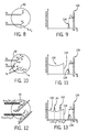
FIGS. 8-13 generally illustrate various interaction effects of electromagnetic energy with a scintillation crystal and impacts on the deposited spectrum; -
FIGS. 14 depicts electromagnetic emissions of barium-133 at various energy levels; -
FIG. 15 depicts a simulated crystal response function in accordance with one embodiment; -
FIG. 16 generally depicts determination of a crystal impulse response for a scintillation crystal in accordance with one embodiment; -
FIG. 17 depicts simulated individual spectral responses of a scintillation crystal for various incident energy levels in accordance with one embodiment; -
FIG. 18 generally illustrates additional details of the photomultiplier tube ofFIG. 6 in accordance with one embodiment; -
FIG. 19 depicts deconvolution kernel components based on the individual spectral responses ofFIG. 17 in accordance with one embodiment; -
FIG. 20 is a block diagram of electronic components of the apparatus ofFIG. 1 in accordance with one embodiment; -
FIG. 21 is a graph generally depicting synchronous pulses generated by the photomultiplier tube in accordance with one embodiment; -
FIG. 22 is a flow chart for inferring incident count rates using a physical model of a detector in accordance with one embodiment; -
FIG. 23 is a flow chart for determining phase fractions of a fluid through spectrum deconvolution in accordance with one embodiment; -
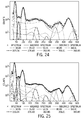
FIGS. 24-27 are examples of spectrum deconvolutions for various radioactive sources and detector types in accordance with certain embodiments; -
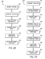
FIG. 28 is a flow chart for calculating incident count rates, attenuation, and phase fractions of a fluid in accordance with one embodiment; and -
FIG. 29 is a flow chart for optimizing variables of a detector response model to calculate characteristics of a fluid of interest in accordance with one embodiment. - It is to be understood that the present disclosure provides many different embodiments, or examples, for implementing different features of various embodiments. Specific examples of components and arrangements are described below for purposes of explanation and to simplify the present disclosure. These are, of course, merely examples and are not intended to be limiting.
- When introducing elements of various embodiments, the articles "a," "an," "the," and "said" are intended to mean that there are one or more of the elements. The terms "comprising," "including," and "having" are intended to be inclusive and mean that there may be additional elements other than the listed elements. Moreover, any use of "top," "bottom," "above," "below," other directional terms, and variations of these terms is made for convenience, but does not mandate any particular orientation of the components.
- Turning now to the drawings, an
apparatus 10 in the form of a flow meter is generally depicted inFIG. 1 in accordance with one embodiment. While certain elements of theapparatus 10 are depicted in this figure and generally discussed below, it will be appreciated that theapparatus 10 may include other components in addition to, or in place of, those presently illustrated and discussed. Moreover, while theapparatus 10 may be provided in the form of a flow meter (e.g., a multiphase flow meter) as described below in connection with certain embodiments, theapparatus 10 could be provided in other forms as well. - As depicted, the apparatus includes a
fluid conduit 12 for receiving a fluid. Theapparatus 10 also includes anemitter 14 of electromagnetic radiation, adetector 16 of electromagnetic radiation, a pressure sensor 18 (e.g., one or both of a pressure transmitter and a differential-pressure transmitter), and one or more additional sensors 20 (e.g., a temperature sensor). To facilitate certain measurements, such as flow rate, thefluid conduit 12 can have a tapered bore (e.g., a Venturi throat) to constrict fluid flow. Further, in at least one embodiment theemitter 14 anddetector 16 are positioned about a Venturi throat in thefluid conduit 12 such that thedetector 16 receives radiation that has been transmitted through fluid within the Venturi throat. - The
apparatus 10 further includes a computer 22 (which may also be variously referred to as a controller or a control unit) for determining characteristics of fluid within thefluid conduit 12. In at least some embodiments, thecomputer 22 is provided in the form of a flow computer coupled with the other depicted components in a single unit to facilitate installation of a flow meter in a larger system (e.g., an oilfield apparatus). More specifically, thecomputer 22 is operable to determine characteristics of fluid within thefluid conduit 12 from measurements collected by the other components. For example, thecomputer 22 can determine pressure and flow rate of the fluid. Further, acomputer 22 of a multiphase flow meter can determine the attenuation of the fluid with respect to various levels of electromagnetic radiation by comparing the amount of radiation emitted from theemitter 14 to the portion of such radiation actually received by thedetector 16. Such acomputer 22 can also use this information to calculate phase fractions (e.g., proportions of oil, gas, and water) for a multiphase fluid within thefluid conduit 12. Finally, single-phase flow rates can be achieved by combining the phase fraction measurements together with the total flow rate measurement. Often, a multiphase flow model is implemented to compensate for differences between the velocities of liquid and gas in the fluid. - The
computer 22 can be a processor-based system, an example of which is provided inFIG. 2 . In this depicted embodiment, thecomputer 22 includes at least oneprocessor 30 connected, by abus 32, to volatile memory 34 (e.g., random-access memory) and non-volatile memory 36 (e.g., flash memory and a read-only memory (ROM)).Coded application instructions 38 anddata 40 are stored in thenon-volatile memory 34. For example, theapplication instructions 38 can be stored in a ROM and thedata 40 can be stored in a flash memory. Theinstructions 38 and thedata 40 may be also be loaded into the volatile memory 34 (or in alocal memory 42 of the processor) as desired, such as to reduce latency and increase operating efficiency of thecomputer 22. Thecoded application instructions 38 can be provided as software that may be executed by theprocessor 30 to enable various functionalities described herein. Non-limiting examples of these functionalities include deconvolution of a measured energy spectrum, determination of incident photon count rates on a detector, and calculation of attenuation rates and phase fractions for a fluid. In at least some embodiments, theapplication instructions 38 are encoded in a non-transitory computer readable storage medium, such as thevolatile memory 34, thenon-volatile memory 36, thelocal memory 42, or a portable storage device (e.g., a flash drive or a compact disc). - An interface 44 of the
computer 22 enables communication between theprocessor 30 andvarious input devices 46 andoutput devices 48. The interface 44 can include any suitable device that enables such communication, such as a modem or a serial port. In some embodiments, theinput devices 46 include one or more sensing components of the apparatus 10 (e.g.,detector 16,pressure sensors 18, other sensors 20) and theoutput devices 48 include displays, printers, and storage devices that allow output of data received or generated by thecomputer 22.Input devices 46 andoutput devices 48 may be provided as part of thecomputer 22 or may be separately provided. - Further, while the
computer 22 could be located with thefluid conduit 12 and sensing components of theapparatus 10 as a unitary system (e.g., a flow meter), thecomputer 22 could also be located remote from the other components. Further, thecomputer 22 could be provided as a distributed system with a portion of thecomputer 22 located with the sensing components at thefluid conduit 12 and the remaining portion of thecomputer 22 located remote from thefluid conduit 12. - Additional details regarding operation of the
emitter 14 and thedetector 16 may be better understood with reference toFIGS. 3 and 4 . Theemitter 14 and thedetector 16, which may also be referred to as components of a spectrometer ordensitometer 50, are arranged about thefluid conduit 12 in any suitable manner that allows thedetector 16 to receive electromagnetic radiation transmitted through fluid within thefluid conduit 12 from theemitter 14. As presently shown, theemitter 14 and thedetector 16 are coupled opposite one another about thefluid conduit 12.Fluid 52 within thefluid conduit 12 is irradiated withelectromagnetic radiation 54. Some of theelectromagnetic radiation 54 is absorbed or scattered by the fluid 52, but a portion of theelectromagnetic radiation 54 is received by thedetector 16.Windows emitter 14 and thedetector 16 from the fluid 52, while still permitting theelectromagnetic radiation 54 to be transmitted from theemitter 14 and received by thedetector 16. Particularly, thewindows emitter 14 and read by thedetector 16. - The
emitter 14 can produce electromagnetic radiation of any suitable frequency and energy within the electromagnetic spectrum. For instance, in some embodiments theemitter 14 includes one or more radioactive sources that emit gamma rays and x-rays. Other embodiments could includenon-radioactive emitters 14, such as an electric x-ray generator, in full accordance with the present techniques. - As generally shown in
FIG. 4 , theemitter 14 and thedetector 16 can be positioned on opposite sides of aVenturi throat 62 in thefluid conduit 12. This arrangement allows measurement of the linear attenuation coefficient, λ m (E), of the fluid 52 for electromagnetic radiation at a given energy E according to the Beer-Lambert law:
in which d is thethroat diameter 64, N(E) is the amount of transmitted photons (the quantity of photons detected by the detector 16), and N 0(E) is the empty pipe count rates (the quantity of photons emitted from theemitter 14 that would reach thedetector 16 but for interference by a medium, such as the fluid 52, in the throat 62). - In some instances, the analyzed fluid can have multiple phases. For example, the fluid 52 can be a multiphase fluid having an oily liquid phase, an aqueous liquid phase, and a gaseous phase, which may be more generally referred to as oil, water, and gas phases. It will be appreciated by those skilled in the art that the attenuation of electromagnetic radiation by a multiphase fluid is a linear combination of the attenuations caused by each of its phases weighted by their proportions in the fluid. In the case of a fluid having some combination of oil, water, and gas, this can be written as:

where λ g , λ w , and λ o are attenuation coefficients for gas, water, and oil for radiation of a given energy level E, and α g , α w , and α o are respective fractional portions of each phase within the analyzed fluid (also referred to herein as phase hold-ups or phase fractions). - This gives as many equations as the number of distinct energy levels in the electromagnetic radiation from the
emitter 14. Further considering that the three phase hold-ups sum up to 1, the following system of linear equations can be achieved:
The attenuation matrix above (i.e., the matrix including the phase-specific attenuation coefficients for n energy levels) can be obtained from full bore measurements on each phase, hereafter called the in-situ references, or theoretical coefficients can be used. This attenuation matrix can then be inverted (giving an inversion matrix A -1) to calculate the phase hold-ups:
- The equations above relating the phase attenuations and phase fractions to the measured attenuation coefficients for the multiphase fluid assume the energy levels E 1 ... En emitted from a source can be independently measured by the detector. In reality, however, the detector response is not ideal and some higher-energy photons can be accounted in lower-energy regions or, conversely, lower-energy photons can be accounted in higher-energy regions. Due to this mixing of incident energies, the phase hold-ups can eventually be biased when inverting the attenuation matrix. Likewise, the detector response may drift over time because of temperature fluctuations or due to its own aging. As a consequence, the real-time count rates may differ from the in-situ references (which could have been acquired several days or months before, for example). This can also lead to a systematic error on the phase hold-ups.
- To compensate for these two sources of error, each part of the detection process can be modeled. Moreover, rather than recording just certain electromagnetic emissions and then using an empirical model to compensate for variance between real and ideal detector response, at least some embodiments of the present disclosure use the
detector 16 to measure the full energy spectrum of theelectromagnetic radiation 54. And as described in greater detail below, such embodiments can then use a physical model of the response of thedetector 16 to determine count rates for photons of different energy levels of interest that are incident on thedetector 16. In at least some instances, the measurement of the full energy spectrum and use of the physical model enables the detection chain of theapparatus 10 to be insensitive to temperature, aging drifts, and source activity variations. These features also allow the presently disclosed techniques for determining incident count rates to be broadly applicable to any types of sources, detector technologies, and source-detector geometries. - Additional features of the
emitter 14 and thedetector 16 are depicted inFIG. 5 as part of asystem 70 in accordance with certain embodiments. In this example, theemitter 14 includes asource 72 of electromagnetic radiation. As noted above, thesource 72 can be a radioactive source, such as barium-133 or americium-241. The selection of thesource 72 can be based on the fluid intended to be analyzed. For instance, americium-241 could be used if the fluid 52 is a wet gas and barium-133 could be used in other cases. Fluorescent sources, which generally emit lower-energy spectra than radioactive sources, could also be used. In addition to thewindows system 70 includes acollimator 74. Thecollimator 74 has an opening, such as a slit, that forms a beam of electromagnetic radiation that is directed toward thescintillator 80. As presently depicted, thecollimator 74 is on the detector side of the system, so that electromagnetic radiation transmitted through the fluid is collimated for receipt by thescintillator 80. This helps filter out scattered photons from the radiation passed to thescintillator 80. But thecollimator 74 could be provided at other positions within thesystem 70. - The
detector 16 is illustrated as a scintillation detector inFIG. 5 , though the detector could be a solid-state detector in other embodiments. As depicted, thedetector 16 includes ascintillator 80, a photomultiplier tube (PMT) 82, and anamplifier 84. Thescintillator 80 can be provided in various forms, such as a crystal. In some embodiments, thescintillator 80 is a NaI(Tl) (sodium iodide doped with thallium) detector or a YAP(Ce) (yttrium aluminum perovskite activated with cerium) detector. - The
scintillator 80 collects at least a portion of the incident photon energy it receives and converts this incident energy into radiation in a different part of the electromagnetic spectrum. For example, as depicted as part of adetection chain 90 inFIG. 6 , high-energy radiation 94 (e.g., x-rays and gamma rays) can be absorbed by the scintillator (here provided as a scintillation crystal 92) to cause it to radiate pulses oflight 96, such as visible light. ThePMT 82, which can be optically coupled to thescintillation crystal 92, detects electromagnetic radiation (e.g., light 96) emitted from thescintillation crystal 92 and converts this radiation intoelectrical charges 98. Theamplifier 84 then transforms these electrical charges into electrical signals, such asvoltage pulses 100, suitable for analog-to-digital processing. - In at least some embodiments, a physical model of the response of the
detector 16 is created. The physical model can generally include models for each part of a detection chain. This physical model can also be stored in thecomputer 22 and, as described below, can be used to facilitate determination of incident count rates at thedetector 16 and the calculation of phase fractions for an analyzed fluid. - One example of a process for creating a physical model of the response of a scintillation detector is generally represented by
flow chart 110 inFIG. 7 . In this embodiment, the components of thedetection chain 90 are themselves modeled as response functions that relate inputs at each component to corresponding outputs. Particularly, as shown inFIG. 7 , a response function for thescintillation crystal 92 is determined atblock 112, a response function for thePMT 82 is determined atblock 114, and a response function for theamplifier 84 is determined atblock 116. It will be appreciated, however, that components of a solid-state detector could be similarly modeled in another embodiment. The determination of these response functions for a scintillation detector is described in greater detail below by way of example. - In x-ray and gamma-ray spectroscopy, photons deposit their energy into a detector (e.g., the
scintillation crystal 92 or a semiconductor) through matter interaction effects, thus generating an energy spectrum. Even by considering an ideally perfect deposited-energy-to-electric-signal conversion process resulting in a discrete spectrum, due to the finite size of the detector the recovered spectrum is continuous: photons emitted with energy hv have a probability of being measured with smaller energies. As described in detail below, some embodiments of the present disclosure include inferring the number and energy of photons incident on the detector from a measured spectrum. It should be appreciated that the accuracy of such inferences in at least some embodiments will depend on the accuracy of a physical model of the detector response. - Determining the crystal response function at
block 112 includes determining a crystal impulse response h(e',e) that relates an incident spectrum i(e) of theelectromagnetic radiation 94 on thescintillation crystal 92 to a deposited spectrum d(e) inside the scintillation crystal. As will be appreciated, photons in theelectromagnetic radiation 94 interact with atoms of thescintillation crystal 92 to generate light 96. Examples of such interactions are generally described below with reference toFIGS. 8-13 . For the sake of simplicity, these examples depict photons with energy hv hitting ascintillation crystal 92 of finite size. Notable mechanisms of gamma-ray and x-ray interaction with matter include photoelectric absorption, Compton scattering (incoherent scattering), and, in the case of gamma-rays with energy hv > 1.022 MeV, pair production. - In the case of photoelectric absorption generally depicted in
FIG. 8 , the incident gamma-ray (or x-ray) interacts with an electron of an atom of the scintillation crystal 92 (e.g., an electron of the inner electron shell (K-shell) of the atom) and disappears by giving up its energy hv. An electron (e-) is produced from this interaction (i.e., ejected from the atom receiving the incident gamma-ray or x-ray) along with either an x-ray photon or a so-called Auger electron following electron rearrangement due to the vacancy left by the ejected electron. For atomic numbers Z > 39, the probability of generating an x-ray photon is greater than seventy percent and increases with Z. The incident photon energy is often fully deposited in the detector (as is the case with the upper incident ray inFIG. 8 ), thus contributing to a full-energy peak 126 as depicted inFIG. 9 . However, if the effect takes place near the detector surface, an x-ray photon of energy EX may leave the detector (as is the case with the lower incident ray inFIG. 8 ). The deposited energy will then be hv - EX, corresponding to a characteristic x-ray escape peak (EP) 128 in the spectrum shown inFIG. 9 . - As generally shown in
FIG. 10 , in the case of Compton scattering the incident gamma-ray (or x-ray) with energy hv interacts with an electron by giving up part of its energy to the electron itself and being scattered at an angle θ. The portion of energy between the recoil electron and the scattered photon of energy hv'≤hv depends on the scattering angle θ. When both Compton scattering products deposit their energy in the detector (when the scattered photon is eventually photoelectric-absorbed as is the case with the uppermost incident ray inFIG. 10 ), the incident photon contributes to the full-energy peak 126 depicted inFIG. 11 . But when the scattered photon leaves the detector (see, e.g., the middle incident ray inFIG. 10 ), just the recoil electron energy is deposited. The maximum recoil electron energy corresponds to a head-on collision, i.e., θ = π, and is given by:
In the spectrum ofFIG. 11 , this is represented by the Compton edge (CE) 134 at energy Ee-, θ=π and, for 0 ≤ θ ≤ π, recoil electrons generate to the so-calledCompton continuum 136. Moreover, if a scattered photon escapes the detector after multiple Compton scatterings (see, e.g., the lowermost incident ray inFIG. 10 ), the deposited energy will be ε < Ee - < hv - ε, with ε ≅ 0, thus leading to an extra background overlapping the Compton continuum for energies less than or equal to Ee-, θ=π (which, for the sake of clarity, is not shown inFIG. 11 ). - Unlike the previous interaction effects, pair production is a threshold effect. In such an interaction (two of which are generally depicted in
FIG. 12 ) a gamma-ray with energy hv disappears to create an electron-positron pair. Since the electron (and positron) rest mass m 0 corresponds to an energy of m 0 c 2 = 511 keV, the pair creation can take place just if hv ≥ 2 m 0 c 2. In some instances, the annihilation photons from positron-electron annihilation (e + are highly unstable particles) deposit their whole energies in the detector, thus contributing to the full-energy peak 126 inFIG. 13 . In other instances, however, either one or both photons can leave the detector. This leads to the formation of single and double escape peaks 142 and 144 located in the spectrum at hv - m 0 c 2 and hv - 2 m 0 c 2, respectively. - Escape peak intensities and Compton continuum shape may be empirically determined for emissions at a particular energy level with a given detector size and hardware geometry. In the more general scenario of several gamma-ray or x-ray emissions of different energies to be detected, however, such empirical determination becomes increasingly difficult. Even an analytical approach may not provide desired results. For example, on determining the Compton continuum, the Klein-Nishina equation does not provide an accurate quantitative description of the continuum because, among other things, its free electron hypothesis is unrealistic.
- In at least some embodiments of the present disclosure, the complex problem of incident photon recovery from an energy spectrum is represented by Monte Carlo codes, where a combination of nuclear physics and statistics allows an accurate description of radiation-matter interactions. The Monte Carlo N-Particle (MCNP) transport code, developed by and available from Los Alamos National Laboratory of the United States, is used in at least some embodiments to simulate the response of the
scintillation crystal 92 to electromagnetic radiation of different energies, although other codes or algorithms could be used for this simulation in different embodiments (e.g.,Geant 4 from the European Organization for Nuclear Research (CERN)). Once characteristics of the three-dimensional hardware geometry, the radiation source, and the detector are introduced, MCNP takes into account detector-related effects and also simulates gamma-ray interactions with materials surrounding the detector itself. The result is a description of an ideal crystal response function (CRF). - By way of example,
FIG. 14 shows an x-ray and gamma-ray emission spectrum of barium-133 andFIG. 15 illustrates an ideal CRF of a 7-mm thick NaI(Tl) scintillation crystal to the barium-133 radiation as simulated by MCNP. Spectral components in both of these figures are labeled with their respective generation mechanism. Although the spectrum shown inFIG. 15 is single- and double-escape peak free (as the most energetic emission from barium-133 occurs at 383.8 keV, which is less than 2 m 0 c 2), the cumulative interactive effects due to the finite detector size make the spectrum complicated, with many high energy photons sorted in low energy bins. - One embodiment for modeling the impulse response of a scintillation crystal is generally depicted by
flow chart 154 ofFIG. 16 . In order to single out the spectral contribution of each barium-133 emission, the CRF can be simulated for one emission at a time. More specifically, usingMCNP 156 andvarious characteristics 158 of the apparatus (such as characteristics of the radiation source, the detector, and the three-dimensional hardware geometry, as discussed above), monoenergetic responses for multiple energy levels can be simulated (block 160) to generate a set of monoenergetic CRFs that characterize thecrystal impulse response 162. The simulation of the monoenergetic responses can be performed with MCNP or in any other suitable manner. Moreover, as detailed below, this set of monoenergetic CRFs facilitates later determination of the detector incident photons from a measured spectrum. - As the energy deposition process is an energy-varying linear system, the crystal response function is fully characterized by its impulse response h(e',e). Consequently, the deposited spectrum can be computed from the convolution product of the incident spectrum with h(e',e):

This convolution product can also be expressed in a matrix form. If H denotes the energy deposition matrix into the scintillation crystal, Hij = h(ei,ej ), obtained from MCNP (or other) simulations; I refers to the incident spectrum vector, Ik = i(ek ); and D denotes the deposited spectrum vector, Dk = d(ek ), then the convolution equation can also be written in discretized form as:
The crystal response matrix H contains the individual responses to source emissions, such as from barium-133 as discussed above. These individual responses of H (for the example of barium-133 source emissions) are generally depicted inFIG. 17 . Particularly,FIG. 17 depicts the simulated spectral responses of the crystal for various energy levels of incident electromagnetic radiation corresponding to the gamma-ray and K x-ray spectral components ofFIG. 14 . In the present example, these spectral responses are for ten incident energy levels of interest (rounded to the nearest keV): 31 keV, 35 keV, 53 keV, 81 keV, 161 keV, 223 keV, 276 keV, 303 keV, 356 keV, and 384 keV. In other instances, however, the incident energy levels for which the response is simulated could differ from the preceding example. Further, monoenergetic responses could be simulated for a greater or lesser number of incident energy levels in accordance with the present techniques. - Determining the PMT response function at
block 114 ofFIG. 7 includes determining a PMT response function g(e',e) that relates the deposited spectrum d(e) to a smeared spectrum s(e). While here described as a PMT response function for explanatory purposes, it is noted that a solid-state detector that does not have a PMT could also be similarly modeled. In the case of solid-state detectors, the smearing effect would result from the charge collection process rather than the electron multiplication process noted below. - Additional details of a
PMT 82 are generally illustrated in diagram 170 ofFIG. 18 in accordance with one embodiment. As previously noted, thescintillation crystal 92converts incident radiation 94 into pulses oflight 96, which is measured and converted intoelectrical signals 98 by thePMT 82. As depicted in the present figure, photons of light 96 from thescintillation crystal 92 fall on a light-sensitive layer in the form of aphotocathode 172, causing the photocathode to emit photoelectrons. These photoelectrons are focused electrostatically onto a series ofdynodes 174 that progressively amplify the current associated with the emitted photoelectrons. The amplified signal is collected at ananode 176 in the form of current pulses 98 (which can be passed to theamplifier 84 as described above). - Due to the statistical nature of the electron multiplication process of PMTs, the output charge can vary from one event to the other. This uncertainty follows a Poisson process which results in a spectral broadening (i.e., smearing) of the ideal CRF Dirac peaks. This spectral broadening can be approximated by a Gaussian filter whose parameters will depend on the crystal-PMT linearity and resolution. A photon depositing in the crystal the energy ej will be recorded in average at the channel µ(ej ) with a standard deviation σ(ej ). These two functions (which are energy and resolution response models) are specific to each detector assembly (more specifically, the crystal-PMT assembly in those embodiments using a crystal scintillator) and can be parameterized the following way or based on any other energy relationship:
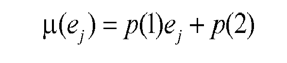

In some embodiments, the parameters p(1), p(2), p(3), and p(4) are adjusted continuously in real time to account for temperature or aging drifts that may occur over a detector's lifetime. In other embodiments, these parameters are adjusted continually, such as periodically at any specified frequency (e.g., once per minute). - As it is an energy-varying linear system, the PMT response function is fully characterized by its impulse response g(e',e). The smeared spectrum can therefore be computed from the convolution product of the deposited spectrum with g(e',e):

This convolution product can also be expressed in a matrix form. For example, if G(P) is a Gaussian matrix, gij = g(ei,ej ), based on the energy and resolution response models above; D is the deposited spectrum vector, Dk = d(ek ); and S is the smeared spectrum vector, Sk = s(ek ), then the convolution equation can be written in discretized form as:
The product matrix G(P)H can be referred to as the deconvolution kernel. This deconvolution kernel characterizes the impulse response of thescintillation crystal 92 and thePMT 82. The deconvolution kernel also contains the single energy spectra (components) from which observed spectrums are created. These single energy spectra are generally depicted inFIG. 19 , and it is noted that each depicted spectrum is a smeared version of an associated spectrum depicted inFIG. 17 . - Returning again briefly to
FIG. 7 , determining the amplifier response function atblock 116 includes determining an amplifier response function f which relates the smeared spectrum s(e) to an observed spectrum o(e). Each output of thePMT 82 described above is, in essence, an amount of electrical charge proportional to the amount of energy in a photon (e.g., a gamma-ray or x-ray photon) deposited in thescintillation crystal 92. Electrical components, such as theamplifier 84 and a multi-channel analyzer, then collect that charge, measure its amplitude, and store it in the spectrum. - One example of such components is shown in
FIG. 20 . In this embodiment, the electrical components include apreamplifier 184, a shapingamplifier 186, and a multi-channel analyzer (MCA) 188. Thepreamplifier 184 and the shapingamplifier 186 may be components of the amplifier 84 (FIG. 6 ), while theMCA 188 can be included as part of thedetector 16, part of the computer 22 (e.g., as an input device 46), or as a separate component. Thepreamplifier 184 converts and amplifies thecurrent pulses 98 it receives from thePMT 82 into voltage pulses. The shapingamplifier 186 transforms these voltage pulses into linear pulses, such as unipolar or bipolar semi-Gaussian pulses, having faster baseline restoration and better signal-to-noise ratio. - The
multi-channel analyzer 188 includesanalyzer circuitry 190 for sorting the linear pulses into respective channels. TheMCA 188 could include any suitable number of measurement channels for sorting linear pulses received from the shapingamplifier 186. For example, in some embodiments theMCA 188 has 512 channels or 1024 channels. When two incident photons arrive at the detector within the width of the shaping amplifier output pulse, their respective pulses pile up to form an output pulse of distorted height, leading to a distorted energy spectrum. While post-processing algorithms may be able to describe the effect of pulse pile-up on the spectrum in some instances, they can also be too resource-intensive (e.g., in CPU processing cycles) for certain (e.g., real-time) implementations. - Accordingly, the depicted
MCA 188 includes a pile-up rejector 192. This pile-up rejector 192 discards pile-up events in which their time interval is longer than a threshold pile-up rejection time. The threshold pile-up rejection time can be set to any desired level, such as a level that would result in the discarding of most pile-up events. This can simplify the interpretation of the spectrum distortion by generally reducing pile-up effects to the case of synchronous pulses. In order to model the distortion due to these left-over synchronous pulses, a quantitative analysis is performed on each channel k of the spectrum. It is possible to demonstrate from Poisson's law that the probability of two photons piling-up is:
where τ is the pile-up rejection time and ntot is the total count rate. - An example of synchronous pulses is generally represented in the graph of
FIG. 21 , in which a pulse 200 (with amplitude i) is synchronous with a pulse 202 (with amplitude j), resulting in acumulative pulse 204 that would be read into a channel k due to the summation of i and j. Further, if i and j denote the incident amplitude combinations, the gains and losses rates can be calculated for each channel k via the following formula:
The observed spectrum is then a balance of gains and losses in each channel:
- Each part of the detection chain has been modeled above in the form of individual response functions. The global detector response can be considered a physical model that combines those individual response functions to represent the functioning of the modeled detector chain. Consequently, this global detector response can be expressed in matrix form as:

- In at least some embodiments, this physical model for detector response is used to infer incident count rates for photons of different energy levels received by the
detector 16. The inferred count rates can then be used to determine characteristics of an analyzed fluid. One example of a process for inferring the incident count rates and then characterizing a fluid based on the inferred count rates is generally represented byflow chart 210 inFIG. 22 . In this embodiment, electromagnetic radiation (e.g., x-rays and gamma rays from emitter 14) is transmitted (block 212) through a fluid of interest. The fluid attenuates the radiation such that a portion of the radiation is received (block 214) at a detector (e.g., detector 16). Atblock 216, the energy spectrum of the radiation received by the detector is measured, which may be performed by a multi-channel analyzer such as that described above. In at least some instances, the full energy spectrum of the received radiation is measured. In others, a partial energy spectrum can be measured, such as a portion of the energy spectrum falling within a contiguous range of multiple channels of a multi-channel analyzer. But it is noted that, as used herein, measurement of the energy spectrum (whether a full energy spectrum or a partial energy spectrum) means measurement of counts within numerous channels of a multi-channel analyzer, rather than merely measuring counts in a handful of channels (e.g., two to ten channels isolated from one another) corresponding to particular energy levels of interest. This measurement of the spectrum, rather than of a small number of individual channels, allows incident count rates to be inferred from the measured energy spectrum in accordance with the present techniques. - At
block 218, the measured energy spectrum and the physical model for detector response are used to infer variables of the physical model. For the model described above, inputs of the model include crystal monoenergetic responses H and the detector energy and resolution functions µ(e) and σ(e), and the variables include the incident count rates for photons of different energy levels and the detector-specific parameters p(1), p(2), p(3), and p(4). These variables can be inferred through a deconvolution process based on the detector response function O. - More specifically, in at least some instances the detector response function of the physical model is compared to the measured energy spectrum, which may include performing optimization (e.g., least squares optimization) on the detector response function to fit the detector response function to the measured energy spectrum and infer the incident count rates and detector-specific parameters. For example, letting Y be the measured spectrum, a non-linear least squares algorithm can be used to determine the detector-specific parameters P and the incident count rates I that minimize the following residuals:

The residuals can be weighted by the standard deviation of the measurements, i.e., the square root of counts in this case since counting processes are ordinarily assumed to follow Poisson statistics. A Levenberg-Marquardt algorithm can be used to perform the optimization (in the form of least squares minimization) or a simpler Gauss-Newton technique can be used. Still further, maximum likelihood or maximum entropy methods can be used to perform the optimization, as can any other suitable methods. - Once the incident count rates I are inferred, these count rates can be compared with empty pipe count rates to determine the attenuation of electromagnetic radiation by the analyzed fluid for multiple energy levels, as described above with respect to
FIG. 4 . The determined attenuation can then be used to characterize the fluid (block 220), such as by determining phase fractions for the fluid or information about some additional component, such as hydrogen sulfide or salts in the fluid, as discussed below. Further, the inferred detector-specific parameters P can be used to calibrate the detector (block 222), such as to maintain the spectral output of the detector at a reference position. - In accordance with another embodiment, a process for determining phase fractions of a multiphase fluid is generally represented by
flow chart 230 inFIG. 23 . In this embodiment, electromagnetic radiation is emitted (block 232) through a multiphase fluid. For instance, a radioactive source can emit x-rays and gamma rays into a multiphase fluid flowing through a fluid conduit. The radiation incident on a detector is received (block 234) and transformed (block 236) into electrical signals as described above. It will be appreciated that the electrical signals are representative of the incident radiation. - An energy spectrum is determined (block 238) from the electrical signals and then deconvolved (block 240) to estimate quantities of photons of multiple energy levels received by the detector. The deconvolution of the determined energy spectrum (which in at least some instances is the full energy spectrum of the received radiation) can be performed in any suitable manner, such as by fitting a modeled detector response function in the manner described above. Attenuation coefficients for the fluid can be calculated (block 242) and phase fractions can be determined (block 244) based on the attenuation coefficients as described elsewhere herein. The phase fractions in some embodiments include gas, water, and oil phases. Further, the phase fractions could include other components in addition to (or in place of) gas, water, and oil. Still further, information about additional components, such as hydrogen sulfide or salts, could also be determined, as described below.
- Examples of spectrum deconvolutions for various radioactive sources and detector types are generally depicted in
FIGS. 24-27 . In each of these examples, the deconvolution kernel is computed from MCNP simulations based on input characteristics of the radioactive source, the detector, and source-detector geometry. Further, each of these graphs depicts incident photon counts (y-axis) over 512 channels (x-axis). In addition to a measured spectrum, an observed spectrum, and a smeared spectrum, individual spectral components associated with energy lines of the respective radioactive source are also depicted (with the source energy lines enumerated in keV in at the bottom of each of these figures). The data depicted inFIG. 24 is based on a barium-133 radiation source and a 10 mm YAP(Ce) scintillation crystal. InFIG. 25 , the depicted data is also based on a barium-133 radiation source, but with a 2 mm YAP(Ce) scintillation crystal. InFIG. 26 , the depicted data is based on an americium-241 radiation source and a 10 mm YAP(Ce) scintillator. And the data inFIG. 27 is based on radiation source having cesium-137 and sodium-22 with a 25.4 mm (one-inch) YAP(Ce) scintillation crystal. - A further example of a process for calculating incident count rates, attenuation, and phase fractions of a fluid is generally represented by
flow chart 250 inFIG. 28 . In this embodiment, photons of different energies that have passed through a fluid of interest (e.g., a multiphase fluid in a conduit) are received at a detector (block 252) and the energy spectrum of the received photons is then measured (block 254). Spectral components of the measured energy spectrum are derived (block 256) for multiple energy levels of the photons received by the detector. These spectral components can be derived in any suitable manner, including using multiple monoenergetic response functions in the manner described above. Count rates can then be measured (block 258) for at least two energy levels of the received photons based on the derived spectral components. The at least two energy levels can include any energy levels of interest. For example, the received photons can include x-ray photons and gamma-ray photons, and the at least two energy levels can include a first energy level for received x-ray photons and a second energy level for received gamma-ray photons. In some embodiments, such as those using a barium-133 source, the first energy level of received x-ray photons is between 30 keV and 36 keV and the second energy level of received gamma-ray photons is between 79 keV and 81 keV. Attenuation rates of the photons by the fluid for the at least two energy levels and phase fractions for the fluid can then be calculated atblocks - Additionally, an example of a process that optimizes variables of a detector response model to enable calculation of fluid characteristics is generally represented by
flow chart 270 inFIG. 29 . In this embodiment, electromagnetic radiation is transmitted through a fluid (block 272) and an attenuated portion of that radiation is received at a scintillation crystal of a detector (block 274). The scintillation crystal emits light in response to the received radiation, and this light is received by a photomultiplier tube (block 276). The light is converted to electrical signals (block 278) to enable measurement of the energy spectrum generated by the radiation received at the scintillation crystal (block 280). Variables of a detector response model can then be optimized, as described above, to minimize residuals between the measured energy spectrum and an output of the detector response model (block 282). The optimized variables of the detector response model can include incident count rates for different energy levels of photons received by the scintillation detector and detector-specific parameters, as also described above. In some embodiments, the residuals are weighted based on a standard deviation of the measured energy spectrum and the variables are optimized with a non-linear, least squares algorithm, such as a Levenberg-Marquardt algorithm or a Gauss-Newton algorithm. Further, attenuation coefficients of the fluid for the different energy levels of radiation and phase proportions (e.g., for water, oil, and gas) can be calculated (blocks 284 and 286). - While the present techniques can be used to determine fractional portions for a multiphase fluid having three components (e.g., oil, water, and gas), they can also be used to determine additional components of the multiphase fluid. In some instances, the present techniques can be applied to cases of fluids having a combination of hydrocarbon liquid (e.g., oil), water, hydrocarbon gas, and some additional component, e.g., hydrogen sulfide or salts. With the present techniques, count rates from distinct energy levels in the electromagnetic radiation from the
emitter 14 can be inferred. This can give as many equations as the number of the energy levels, thus providing a system of linear equations that can be inverted to calculate the fractional components of oil, water and gas as well as further information related to additional components, for instance in the form of change of salt and hydrogen sulfide quantity. The equations regarding the additional components will involve count rates of extra energy levels as well as other physical quantities depending on the chemical behavior of the additional components with oil, water and gas. - From the above description, it will be appreciated that the present disclosure introduces a method of determining phase fractions for a multiphase fluid, the method comprising: receiving electromagnetic radiation transmitted through the multiphase fluid and incident on an electromagnetic radiation detector; transforming the incident electromagnetic radiation to electrical signals representative of the incident electromagnetic radiation; determining an energy spectrum from the electrical signals; deconvolving the determined energy spectrum to estimate quantities of photons of at least two different energy levels in the electromagnetic radiation that are received by the electromagnetic radiation detector; calculating attenuation coefficients for phases of the multiphase fluid for the at least two different energy levels based on the estimated quantities of photons of the at least two different energy levels received by the electromagnetic radiation detector; and determining the phase fractions for the phases of the multiphase fluid based on the calculated attenuation coefficients. In some embodiments, deconvolving the determined energy spectrum includes fitting a modeled detector response function to the determined energy spectrum. Further, in at least one embodiment, deconvolving the determined energy spectrum includes fitting a modeled detector response function having a deconvolution kernel that characterizes the impulse response of one or more components of the electromagnetic radiation detector. Determining the phase fractions for the phases of the multiphase fluid can include determining the phase fractions for a gaseous phase, an aqueous liquid phase, and an oily liquid phase of the multiphase fluid. Also, calculating the attenuation coefficients for the phases of the multiphase fluid can include comparing the estimated quantities of photons of the at least two different energy levels with estimated quantities of photons of the at least two different energy levels emitted from a source of the electromagnetic radiation. Further still, transforming the incident electromagnetic radiation to the electrical signals can include transforming gamma radiation to the electrical signals. And the method can also comprise emitting the electromagnetic radiation from a radioactive source through the multiphase fluid as it flows through a flow meter.
- It will be further appreciated that the present disclosure introduces a device comprising a non-transitory, computer-readable storage medium encoded with application instructions that, when executed by a processor, enable: receiving a measured spectrum representative of electromagnetic radiation incident on a detector; fitting a modeled spectrum to the measured spectrum; and determining from the modeled spectrum count rates for photons of the electromagnetic radiation incident on the detector. In one embodiment, fitting the modeled spectrum to the measured spectrum includes minimizing residuals between the measured spectrum and the modeled spectrum. The non-transitory, computer-readable storage medium can be further encoded with application instructions that, when executed by the processor, enable calculation of phase fractions of a multiphase fluid based on the determined count rates in at least some embodiments. In some instances, the device is a memory device or a computer having the processor and the non-transitory, computer-readable storage medium. Further, in at least one embodiment, such a computer is a flow computer of a multiphase flow meter.
- The present disclosure also introduces an apparatus comprising: a fluid conduit; a radioactive source coupled to the fluid conduit; a sensor coupled to the fluid conduit and configured to receive electromagnetic radiation from the radioactive source, measure the energy spectrum of the received electromagnetic radiation, and output data indicative of the measured energy spectrum; and a controller operable to receive the output data from the sensor and to determine, through deconvolution of the measured energy spectrum, count rates for photons of different energy levels in the electromagnetic radiation received by the sensor. The controller in some embodiments is a flow computer of a multiphase flow meter. The radioactive source can emit gamma radiation and the detector can be configured to detect the gamma radiation. Further, the radioactive source can also emit x-rays and the detector can be configured to detect the x-rays. In some embodiments, the radioactive source includes barium-133. Also, in at least some instances the detector of the apparatus includes a scintillator.
- Further yet, the present disclosure introduces a method comprising: transmitting electromagnetic radiation from a source through a fluid in a conduit; receiving an attenuated portion of the electromagnetic radiation at a scintillation crystal of a detector; receiving, at a photomultiplier tube of the detector, light emitted from the scintillation crystal in response to receipt of the attenuated portion of the electromagnetic radiation received at the scintillation crystal; converting the light received at the photomultiplier tube into electrical signals; measuring, based on the electrical signals, an energy spectrum generated by the attenuated portion of the electromagnetic radiation; and optimizing variables of a response model for the detector to minimize residuals between the measured energy spectrum and an output of the response model, wherein the optimized variables include incident count rates for different energy levels of photons received by the scintillation crystal and detector-specific parameters. This method can also include using at least two of the optimized incident count rates to calculate attenuation coefficients of the fluid for at least two of the different energy levels. Further, in one embodiment the method includes measuring the salinity of the fluid based on at least two of the optimized incident count rates. In some instances, the method also includes calculating the proportions of water, oil, and gas in the fluid based on the calculated attenuation coefficients. Optimizing the variables of the response model to minimize the residuals can include weighting the residuals with a standard deviation of the measured energy spectrum. Also, optimizing the variables of the response model can include optimizing the variables with a non-linear, least squares algorithm. In at least some embodiments, optimizing the variables with a non-linear, least squares algorithm includes optimizing the variables with a Levenberg-Marquardt algorithm or a Gauss-Newton algorithm.
- Additionally, the present disclosure introduces a method comprising modeling a response function of a detector assembly to electromagnetic radiation, the detector assembly having a scintillation crystal, a photomultiplier tube, and an amplifier, wherein modeling the response function of the detector assembly includes: determining a crystal response function that relates an electromagnetic spectrum incident on the scintillation crystal of the detector assembly to an electromagnetic spectrum deposited in the scintillation crystal of the detector assembly; determining a photomultiplier tube response function that relates the electromagnetic spectrum deposited in the scintillation crystal to a smeared spectrum; and determining an amplifier response function that relates the smeared spectrum to an observed spectrum; wherein the response function is defined as the convolution product of the electromagnetic spectrum incident on the scintillation crystal, the crystal response function, the photomultiplier tube response function, and the amplifier response function. In one embodiment of the method, determining the crystal response function includes generating an impulse response matrix for the scintillation crystal through Monte Carlo simulations based on characteristics of: the scintillation crystal, a source of the electromagnetic radiation actually received by the scintillation crystal, and the geometric arrangement of the source and the scintillation crystal with respect to one another. Further, the method can also include storing the modeled response function of the detector assembly in a memory device of a control unit of a multiphase flow meter to enable the control unit to subsequently determine count rates of discrete energy levels of electromagnetic radiation actually received by the scintillation crystal of the detector assembly based on the modeled response function and on comparison of a measured spectrum resulting from the electromagnetic radiation actually received by the scintillation crystal to the modeled response function.
- The foregoing outlines features of several embodiments so that those skilled in the art may better understand aspects of the present disclosure. Those skilled in the art should appreciate that they may readily use the present disclosure as a basis for designing or modifying other processes and structures for carrying out the same purposes or achieving the same advantages of the embodiments introduced herein. Those skilled in the art should also realize that such equivalent constructions do not depart from the spirit and scope of the present disclosure, and that they may make various changes, substitutions and alterations herein without departing from the spirit and scope of the present disclosure.
Claims (14)
- A method comprising:transmitting electromagnetic radiation through a fluid;receiving a portion of the electromagnetic radiation at a detector;measuring the energy spectrum of the portion of the electromagnetic radiation received by the detector; andusing the measured energy spectrum and a physical model of detector response to electromagnetic radiation to infer incident count rates for discrete energy levels of the portion of the electromagnetic radiation received by the detector.
- The method of claim 1, wherein using the measured energy spectrum and the physical model of detector response includes comparing the measured energy spectrum to a detector response function of the physical model to infer the incident count rates.
- The method of claim 2, wherein comparing the measured energy spectrum to the detector response function includes performing least squares optimization of the detector response function with respect to the measured energy spectrum to infer the incident count rates.
- The method of claim 3, wherein the physical model of detector response includes energy and resolution response models having detector-specific parameters, and the method comprises inferring the detector-specific parameters from the least squares optimization between the measured energy spectrum and the detector response function.
- The method of claim 4, comprising calibrating the detector based on the inferred detector-specific parameters.
- The method of claim 1, comprising characterizing a physical attribute of the fluid based on the inferred incident count rates.
- The method of claim 6, wherein the fluid is a multiphase fluid and characterizing a physical attribute of the fluid includes determining phase fractions for the multiphase fluid.
- An apparatus comprising:a detector of electromagnetic radiation;a multi-channel analyzer configured to measure an energy spectrum of electromagnetic radiation received by the detector; anda controller configured to deconvolve the measured energy spectrum using a physical model representative of the response of the detector to characterize the electromagnetic radiation received by the detector.
- The apparatus of claim 8, wherein the controller is configured to determine count rates for photons incident on the detector based on the deconvolution of the measured energy spectrum.
- The apparatus of claim 8, wherein the detector is a solid-state detector.
- The apparatus of claim 8, comprising a multiphase flow meter having the detector, the multi-channel analyzer, and the controller.
- The apparatus of claim 11, wherein the controller is a flow computer operable to calculate phase fractions of a fluid passing through the multiphase flow meter based on the deconvolution of the measured energy spectrum using the physical model representative of the response of the detector.
- The apparatus of claim 8, wherein the detector includes a shaping amplifier for providing to the multi-channel analyzer output pulses indicative of photons received by the detector.
- The apparatus of claim 13, wherein the multi-channel analyzer includes a pile-up rejector configured to discard a shaping amplifier output pulse from the detector that is indicative of multiple photons received by the detector within a width of the shaping amplifier output pulse if a time interval between receipt of the multiple photons exceeds a threshold duration.
Priority Applications (8)
| Application Number | Priority Date | Filing Date | Title |
|---|---|---|---|
| EP13306528.4A EP2871498B1 (en) | 2013-11-08 | 2013-11-08 | Method and apparatus for fluid analysis |
| RU2016122471A RU2665330C2 (en) | 2013-11-08 | 2014-11-07 | Spectral analysis with spectral deconvolution |
| CN201480071435.3A CN105849536B (en) | 2013-11-08 | 2014-11-07 | Spectral Analysis Using Spectral Deconvolution |
| PCT/US2014/064532 WO2015070008A1 (en) | 2013-11-08 | 2014-11-07 | Spectral analysis with spectrum deconvolution |
| US15/034,824 US10126154B2 (en) | 2013-11-08 | 2014-11-07 | Spectral analysis with spectrum deconvolution |
| SA516371084A SA516371084B1 (en) | 2013-11-08 | 2016-05-08 | Spectral Analysis with Spectrum Deconvolution |
| US16/186,854 US20190078916A1 (en) | 2013-11-08 | 2018-11-12 | Spectral analysis with spectrum deconvolution |
| US16/787,369 US11029264B2 (en) | 2013-11-08 | 2020-02-11 | Spectral analysis with spectrum deconvolution |
Applications Claiming Priority (1)
| Application Number | Priority Date | Filing Date | Title |
|---|---|---|---|
| EP13306528.4A EP2871498B1 (en) | 2013-11-08 | 2013-11-08 | Method and apparatus for fluid analysis |
Publications (2)
| Publication Number | Publication Date |
|---|---|
| EP2871498A1 true EP2871498A1 (en) | 2015-05-13 |
| EP2871498B1 EP2871498B1 (en) | 2020-05-13 |
Family
ID=49619858
Family Applications (1)
| Application Number | Title | Priority Date | Filing Date |
|---|---|---|---|
| EP13306528.4A Active EP2871498B1 (en) | 2013-11-08 | 2013-11-08 | Method and apparatus for fluid analysis |
Country Status (1)
| Country | Link |
|---|---|
| EP (1) | EP2871498B1 (en) |
Cited By (1)
| Publication number | Priority date | Publication date | Assignee | Title |
|---|---|---|---|---|
| JP2019518952A (en) * | 2016-05-25 | 2019-07-04 | ライカ マイクロシステムズ シーエムエス ゲゼルシャフト ミット ベシュレンクテル ハフツングLeica Microsystems CMS GmbH | Fluorescence lifetime microscopy with time correlated single photon counting to allow enhanced light intensity |
Citations (6)
| Publication number | Priority date | Publication date | Assignee | Title |
|---|---|---|---|---|
| WO2001025762A1 (en) * | 1999-10-04 | 2001-04-12 | Daniel Industries, Inc. | Apparatus and method for determining oil well effluent characteristics for inhomogeneous flow conditions |
| WO2002050522A1 (en) * | 2000-12-19 | 2002-06-27 | Schlumberger Technology B.V. | Apparatus and a method for characterizing multiphase effluents |
| EP1970702A1 (en) * | 2007-03-05 | 2008-09-17 | Services Pétroliers Schlumberger | Detection of an element in a flow |
| WO2009036337A2 (en) * | 2007-09-12 | 2009-03-19 | University Of Florida Research Foundation, Inc. | Method and apparatus for spectral deconvolution of detector spectra |
| WO2009058964A1 (en) * | 2007-10-30 | 2009-05-07 | Schlumberger Technology Corporation | Method and apparatus for determining volume fractions in a multiphase flow |
| EP2574919A1 (en) * | 2011-09-29 | 2013-04-03 | Service Pétroliers Schlumberger | Apparatus and method for fluid phase fraction determination using X-rays |
-
2013
- 2013-11-08 EP EP13306528.4A patent/EP2871498B1/en active Active
Patent Citations (6)
| Publication number | Priority date | Publication date | Assignee | Title |
|---|---|---|---|---|
| WO2001025762A1 (en) * | 1999-10-04 | 2001-04-12 | Daniel Industries, Inc. | Apparatus and method for determining oil well effluent characteristics for inhomogeneous flow conditions |
| WO2002050522A1 (en) * | 2000-12-19 | 2002-06-27 | Schlumberger Technology B.V. | Apparatus and a method for characterizing multiphase effluents |
| EP1970702A1 (en) * | 2007-03-05 | 2008-09-17 | Services Pétroliers Schlumberger | Detection of an element in a flow |
| WO2009036337A2 (en) * | 2007-09-12 | 2009-03-19 | University Of Florida Research Foundation, Inc. | Method and apparatus for spectral deconvolution of detector spectra |
| WO2009058964A1 (en) * | 2007-10-30 | 2009-05-07 | Schlumberger Technology Corporation | Method and apparatus for determining volume fractions in a multiphase flow |
| EP2574919A1 (en) * | 2011-09-29 | 2013-04-03 | Service Pétroliers Schlumberger | Apparatus and method for fluid phase fraction determination using X-rays |
Non-Patent Citations (2)
| Title |
|---|
| LAVIGNE ET AL: "Extraordinary improvement in scintillation detectors via post-processing with ASEDRA-solution to a 50-year-old problem", SPIE, PO BOX 10 BELLINGHAM WA 98227-0010 USA, 1 January 2008 (2008-01-01), XP040437158 * |
| MENG AND D RAMSDEN L J: "An inter-comparison of three spectral-deconvolution algorithms for gamma-ray spectroscopy", IEEE TRANSACTIONS ON NUCLEAR SCIENCE, IEEE SERVICE CENTER, NEW YORK, NY, US, vol. 47, no. 4, pt 1, 1 August 2000 (2000-08-01), pages 1329 - 1336, XP008141594, ISSN: 0018-9499 * |
Cited By (2)
| Publication number | Priority date | Publication date | Assignee | Title |
|---|---|---|---|---|
| JP2019518952A (en) * | 2016-05-25 | 2019-07-04 | ライカ マイクロシステムズ シーエムエス ゲゼルシャフト ミット ベシュレンクテル ハフツングLeica Microsystems CMS GmbH | Fluorescence lifetime microscopy with time correlated single photon counting to allow enhanced light intensity |
| JP7004675B2 (en) | 2016-05-25 | 2022-02-10 | ライカ マイクロシステムズ シーエムエス ゲゼルシャフト ミット ベシュレンクテル ハフツング | Fluorescence lifetime microscopy with time-correlated single photon counting tolerate increased light intensity |
Also Published As
| Publication number | Publication date |
|---|---|
| EP2871498B1 (en) | 2020-05-13 |
Similar Documents
| Publication | Publication Date | Title |
|---|---|---|
| US11029264B2 (en) | Spectral analysis with spectrum deconvolution | |
| US10845502B2 (en) | Optimization of neutron-gamma tools for inelastic gamma-ray logging | |
| US9310513B2 (en) | Method and apparatus for borehole logging | |
| US8907270B2 (en) | Method and apparatus for gain regulation in a gamma detector | |
| US10466384B2 (en) | Techniques for determining formation composition from measured nuclear spectra | |
| US8700333B2 (en) | Apparatus and algorithm for measuring formation bulk density | |
| EP2871478B1 (en) | Method for analyzing fluid and multiphase flow meter | |
| US9658361B2 (en) | Lithology pair ratio: a ratio-based lithology indicator using pair production | |
| US11815478B2 (en) | Through-tubing, cased-hole sealed material density evaluation using gamma ray measurements | |
| Anagnostakis | Environmental radioactivity measurements and applications–difficulties, current status and future trends | |
| Reeder et al. | Gain calibration of a β/γ coincidence spectrometer for automated radioxenon analysis | |
| CN116611026B (en) | Aviation gamma energy spectrum data fusion processing method and system | |
| Meric et al. | Produced water characterization by prompt gamma-ray neutron activation analysis | |
| EP2871498B1 (en) | Method and apparatus for fluid analysis | |
| Jeon et al. | Optimization of gamma-ray detectors in neutron-induced gamma-ray spectroscopy for geophysical applications | |
| EP2927650A1 (en) | Fluid analysis using electron-positron annihilation | |
| Drescher | Characterization of LaBr₃: Ce detectors in a gamma-gamma coincidence configuration | |
| De Meijer et al. | Measured and simulated spectra for a 22Na source in a well counter | |
| Mano et al. | Addressing spectral variability with spectral unmixing for radionuclides automatic detection and quantification in the context of embedded measurements | |
| Fan et al. | Assessment of Cement Density via Through-Casing X-Ray Logging Technique | |
| HK1154661A (en) | Method and apparatus for borehole logging |
Legal Events
| Date | Code | Title | Description |
|---|---|---|---|
| PUAI | Public reference made under article 153(3) epc to a published international application that has entered the european phase |
Free format text: ORIGINAL CODE: 0009012 |
|
| 17P | Request for examination filed |
Effective date: 20131108 |
|
| AK | Designated contracting states |
Kind code of ref document: A1 Designated state(s): AL AT BE BG CH CY CZ DE DK EE ES FI FR GB GR HR HU IE IS IT LI LT LU LV MC MK MT NL NO PL PT RO RS SE SI SK SM TR |
|
| AX | Request for extension of the european patent |
Extension state: BA ME |
|
| R17P | Request for examination filed (corrected) |
Effective date: 20151106 |
|
| RBV | Designated contracting states (corrected) |
Designated state(s): AL AT BE BG CH CY CZ DE DK EE ES FI FR GB GR HR HU IE IS IT LI LT LU LV MC MK MT NL NO PL PT RO RS SE SI SK SM TR |
|
| STAA | Information on the status of an ep patent application or granted ep patent |
Free format text: STATUS: EXAMINATION IS IN PROGRESS |
|
| 17Q | First examination report despatched |
Effective date: 20180504 |
|
| REG | Reference to a national code |
Ref country code: DE Ref legal event code: R079 Ref document number: 602013069029 Country of ref document: DE Free format text: PREVIOUS MAIN CLASS: G01V0005120000 Ipc: G01N0033280000 |
|
| GRAP | Despatch of communication of intention to grant a patent |
Free format text: ORIGINAL CODE: EPIDOSNIGR1 |
|
| RIC1 | Information provided on ipc code assigned before grant |
Ipc: G01N 33/28 20060101AFI20191025BHEP |
|
| STAA | Information on the status of an ep patent application or granted ep patent |
Free format text: STATUS: GRANT OF PATENT IS INTENDED |
|
| INTG | Intention to grant announced |
Effective date: 20191205 |
|
| GRAS | Grant fee paid |
Free format text: ORIGINAL CODE: EPIDOSNIGR3 |
|
| GRAL | Information related to payment of fee for publishing/printing deleted |
Free format text: ORIGINAL CODE: EPIDOSDIGR3 |
|
| GRAS | Grant fee paid |
Free format text: ORIGINAL CODE: EPIDOSNIGR3 |
|
| GRAA | (expected) grant |
Free format text: ORIGINAL CODE: 0009210 |
|
| STAA | Information on the status of an ep patent application or granted ep patent |
Free format text: STATUS: THE PATENT HAS BEEN GRANTED |
|
| AK | Designated contracting states |
Kind code of ref document: B1 Designated state(s): AL AT BE BG CH CY CZ DE DK EE ES FI FR GB GR HR HU IE IS IT LI LT LU LV MC MK MT NL NO PL PT RO RS SE SI SK SM TR |
|
| REG | Reference to a national code |
Ref country code: GB Ref legal event code: FG4D |
|
| REG | Reference to a national code |
Ref country code: CH Ref legal event code: EP |
|
| REG | Reference to a national code |
Ref country code: DE Ref legal event code: R096 Ref document number: 602013069029 Country of ref document: DE |
|
| REG | Reference to a national code |
Ref country code: AT Ref legal event code: REF Ref document number: 1270947 Country of ref document: AT Kind code of ref document: T Effective date: 20200615 |
|
| REG | Reference to a national code |
Ref country code: NO Ref legal event code: T2 Effective date: 20200513 |
|
| REG | Reference to a national code |
Ref country code: LT Ref legal event code: MG4D |
|
| REG | Reference to a national code |
Ref country code: NL Ref legal event code: MP Effective date: 20200513 |
|
| PG25 | Lapsed in a contracting state [announced via postgrant information from national office to epo] |
Ref country code: SE Free format text: LAPSE BECAUSE OF FAILURE TO SUBMIT A TRANSLATION OF THE DESCRIPTION OR TO PAY THE FEE WITHIN THE PRESCRIBED TIME-LIMIT Effective date: 20200513 Ref country code: FI Free format text: LAPSE BECAUSE OF FAILURE TO SUBMIT A TRANSLATION OF THE DESCRIPTION OR TO PAY THE FEE WITHIN THE PRESCRIBED TIME-LIMIT Effective date: 20200513 Ref country code: PT Free format text: LAPSE BECAUSE OF FAILURE TO SUBMIT A TRANSLATION OF THE DESCRIPTION OR TO PAY THE FEE WITHIN THE PRESCRIBED TIME-LIMIT Effective date: 20200914 Ref country code: IS Free format text: LAPSE BECAUSE OF FAILURE TO SUBMIT A TRANSLATION OF THE DESCRIPTION OR TO PAY THE FEE WITHIN THE PRESCRIBED TIME-LIMIT Effective date: 20200913 Ref country code: GR Free format text: LAPSE BECAUSE OF FAILURE TO SUBMIT A TRANSLATION OF THE DESCRIPTION OR TO PAY THE FEE WITHIN THE PRESCRIBED TIME-LIMIT Effective date: 20200814 Ref country code: LT Free format text: LAPSE BECAUSE OF FAILURE TO SUBMIT A TRANSLATION OF THE DESCRIPTION OR TO PAY THE FEE WITHIN THE PRESCRIBED TIME-LIMIT Effective date: 20200513 |
|
| PG25 | Lapsed in a contracting state [announced via postgrant information from national office to epo] |
Ref country code: LV Free format text: LAPSE BECAUSE OF FAILURE TO SUBMIT A TRANSLATION OF THE DESCRIPTION OR TO PAY THE FEE WITHIN THE PRESCRIBED TIME-LIMIT Effective date: 20200513 Ref country code: HR Free format text: LAPSE BECAUSE OF FAILURE TO SUBMIT A TRANSLATION OF THE DESCRIPTION OR TO PAY THE FEE WITHIN THE PRESCRIBED TIME-LIMIT Effective date: 20200513 Ref country code: RS Free format text: LAPSE BECAUSE OF FAILURE TO SUBMIT A TRANSLATION OF THE DESCRIPTION OR TO PAY THE FEE WITHIN THE PRESCRIBED TIME-LIMIT Effective date: 20200513 Ref country code: BG Free format text: LAPSE BECAUSE OF FAILURE TO SUBMIT A TRANSLATION OF THE DESCRIPTION OR TO PAY THE FEE WITHIN THE PRESCRIBED TIME-LIMIT Effective date: 20200813 |
|
| REG | Reference to a national code |
Ref country code: AT Ref legal event code: MK05 Ref document number: 1270947 Country of ref document: AT Kind code of ref document: T Effective date: 20200513 |
|
| PG25 | Lapsed in a contracting state [announced via postgrant information from national office to epo] |
Ref country code: NL Free format text: LAPSE BECAUSE OF FAILURE TO SUBMIT A TRANSLATION OF THE DESCRIPTION OR TO PAY THE FEE WITHIN THE PRESCRIBED TIME-LIMIT Effective date: 20200513 Ref country code: AL Free format text: LAPSE BECAUSE OF FAILURE TO SUBMIT A TRANSLATION OF THE DESCRIPTION OR TO PAY THE FEE WITHIN THE PRESCRIBED TIME-LIMIT Effective date: 20200513 |
|
| PG25 | Lapsed in a contracting state [announced via postgrant information from national office to epo] |
Ref country code: CZ Free format text: LAPSE BECAUSE OF FAILURE TO SUBMIT A TRANSLATION OF THE DESCRIPTION OR TO PAY THE FEE WITHIN THE PRESCRIBED TIME-LIMIT Effective date: 20200513 Ref country code: IT Free format text: LAPSE BECAUSE OF FAILURE TO SUBMIT A TRANSLATION OF THE DESCRIPTION OR TO PAY THE FEE WITHIN THE PRESCRIBED TIME-LIMIT Effective date: 20200513 Ref country code: RO Free format text: LAPSE BECAUSE OF FAILURE TO SUBMIT A TRANSLATION OF THE DESCRIPTION OR TO PAY THE FEE WITHIN THE PRESCRIBED TIME-LIMIT Effective date: 20200513 Ref country code: SM Free format text: LAPSE BECAUSE OF FAILURE TO SUBMIT A TRANSLATION OF THE DESCRIPTION OR TO PAY THE FEE WITHIN THE PRESCRIBED TIME-LIMIT Effective date: 20200513 Ref country code: DK Free format text: LAPSE BECAUSE OF FAILURE TO SUBMIT A TRANSLATION OF THE DESCRIPTION OR TO PAY THE FEE WITHIN THE PRESCRIBED TIME-LIMIT Effective date: 20200513 Ref country code: AT Free format text: LAPSE BECAUSE OF FAILURE TO SUBMIT A TRANSLATION OF THE DESCRIPTION OR TO PAY THE FEE WITHIN THE PRESCRIBED TIME-LIMIT Effective date: 20200513 Ref country code: EE Free format text: LAPSE BECAUSE OF FAILURE TO SUBMIT A TRANSLATION OF THE DESCRIPTION OR TO PAY THE FEE WITHIN THE PRESCRIBED TIME-LIMIT Effective date: 20200513 Ref country code: ES Free format text: LAPSE BECAUSE OF FAILURE TO SUBMIT A TRANSLATION OF THE DESCRIPTION OR TO PAY THE FEE WITHIN THE PRESCRIBED TIME-LIMIT Effective date: 20200513 |
|
| REG | Reference to a national code |
Ref country code: DE Ref legal event code: R097 Ref document number: 602013069029 Country of ref document: DE |
|
| PG25 | Lapsed in a contracting state [announced via postgrant information from national office to epo] |
Ref country code: SK Free format text: LAPSE BECAUSE OF FAILURE TO SUBMIT A TRANSLATION OF THE DESCRIPTION OR TO PAY THE FEE WITHIN THE PRESCRIBED TIME-LIMIT Effective date: 20200513 Ref country code: PL Free format text: LAPSE BECAUSE OF FAILURE TO SUBMIT A TRANSLATION OF THE DESCRIPTION OR TO PAY THE FEE WITHIN THE PRESCRIBED TIME-LIMIT Effective date: 20200513 |
|
| PLBE | No opposition filed within time limit |
Free format text: ORIGINAL CODE: 0009261 |
|
| STAA | Information on the status of an ep patent application or granted ep patent |
Free format text: STATUS: NO OPPOSITION FILED WITHIN TIME LIMIT |
|
| 26N | No opposition filed |
Effective date: 20210216 |
|
| PG25 | Lapsed in a contracting state [announced via postgrant information from national office to epo] |
Ref country code: SI Free format text: LAPSE BECAUSE OF FAILURE TO SUBMIT A TRANSLATION OF THE DESCRIPTION OR TO PAY THE FEE WITHIN THE PRESCRIBED TIME-LIMIT Effective date: 20200513 |
|
| REG | Reference to a national code |
Ref country code: DE Ref legal event code: R119 Ref document number: 602013069029 Country of ref document: DE |
|
| PG25 | Lapsed in a contracting state [announced via postgrant information from national office to epo] |
Ref country code: MC Free format text: LAPSE BECAUSE OF FAILURE TO SUBMIT A TRANSLATION OF THE DESCRIPTION OR TO PAY THE FEE WITHIN THE PRESCRIBED TIME-LIMIT Effective date: 20200513 |
|
| REG | Reference to a national code |
Ref country code: CH Ref legal event code: PL |
|
| PG25 | Lapsed in a contracting state [announced via postgrant information from national office to epo] |
Ref country code: LU Free format text: LAPSE BECAUSE OF NON-PAYMENT OF DUE FEES Effective date: 20201108 |
|
| REG | Reference to a national code |
Ref country code: BE Ref legal event code: MM Effective date: 20201130 |
|
| PG25 | Lapsed in a contracting state [announced via postgrant information from national office to epo] |
Ref country code: LI Free format text: LAPSE BECAUSE OF NON-PAYMENT OF DUE FEES Effective date: 20201130 Ref country code: CH Free format text: LAPSE BECAUSE OF NON-PAYMENT OF DUE FEES Effective date: 20201130 |
|
| PG25 | Lapsed in a contracting state [announced via postgrant information from national office to epo] |
Ref country code: IE Free format text: LAPSE BECAUSE OF NON-PAYMENT OF DUE FEES Effective date: 20201108 Ref country code: FR Free format text: LAPSE BECAUSE OF NON-PAYMENT OF DUE FEES Effective date: 20201130 |
|
| PG25 | Lapsed in a contracting state [announced via postgrant information from national office to epo] |
Ref country code: DE Free format text: LAPSE BECAUSE OF NON-PAYMENT OF DUE FEES Effective date: 20210601 |
|
| PG25 | Lapsed in a contracting state [announced via postgrant information from national office to epo] |
Ref country code: TR Free format text: LAPSE BECAUSE OF FAILURE TO SUBMIT A TRANSLATION OF THE DESCRIPTION OR TO PAY THE FEE WITHIN THE PRESCRIBED TIME-LIMIT Effective date: 20200513 Ref country code: MT Free format text: LAPSE BECAUSE OF FAILURE TO SUBMIT A TRANSLATION OF THE DESCRIPTION OR TO PAY THE FEE WITHIN THE PRESCRIBED TIME-LIMIT Effective date: 20200513 Ref country code: CY Free format text: LAPSE BECAUSE OF FAILURE TO SUBMIT A TRANSLATION OF THE DESCRIPTION OR TO PAY THE FEE WITHIN THE PRESCRIBED TIME-LIMIT Effective date: 20200513 |
|
| PG25 | Lapsed in a contracting state [announced via postgrant information from national office to epo] |
Ref country code: MK Free format text: LAPSE BECAUSE OF FAILURE TO SUBMIT A TRANSLATION OF THE DESCRIPTION OR TO PAY THE FEE WITHIN THE PRESCRIBED TIME-LIMIT Effective date: 20200513 |
|
| PG25 | Lapsed in a contracting state [announced via postgrant information from national office to epo] |
Ref country code: BE Free format text: LAPSE BECAUSE OF NON-PAYMENT OF DUE FEES Effective date: 20201130 |
|
| P01 | Opt-out of the competence of the unified patent court (upc) registered |
Effective date: 20231208 |
|
| PGFP | Annual fee paid to national office [announced via postgrant information from national office to epo] |
Ref country code: GB Payment date: 20250918 Year of fee payment: 13 |
|
| PGFP | Annual fee paid to national office [announced via postgrant information from national office to epo] |
Ref country code: NO Payment date: 20251113 Year of fee payment: 13 |