EP2871415A1 - Gaseous fuel burner with high energy and combustion efficiency, low pollutant emission and increased heat transfer - Google Patents
Gaseous fuel burner with high energy and combustion efficiency, low pollutant emission and increased heat transfer Download PDFInfo
- Publication number
- EP2871415A1 EP2871415A1 EP20130800226 EP13800226A EP2871415A1 EP 2871415 A1 EP2871415 A1 EP 2871415A1 EP 20130800226 EP20130800226 EP 20130800226 EP 13800226 A EP13800226 A EP 13800226A EP 2871415 A1 EP2871415 A1 EP 2871415A1
- Authority
- EP
- European Patent Office
- Prior art keywords
- gaseous fuel
- mixing chamber
- mixtures
- chamber
- heat transfer
- Prior art date
- Legal status (The legal status is an assumption and is not a legal conclusion. Google has not performed a legal analysis and makes no representation as to the accuracy of the status listed.)
- Granted
Links
Images


Classifications
-
- F—MECHANICAL ENGINEERING; LIGHTING; HEATING; WEAPONS; BLASTING
- F23—COMBUSTION APPARATUS; COMBUSTION PROCESSES
- F23D—BURNERS
- F23D14/00—Burners for combustion of a gas, e.g. of a gas stored under pressure as a liquid
- F23D14/02—Premix gas burners, i.e. in which gaseous fuel is mixed with combustion air upstream of the combustion zone
-
- F—MECHANICAL ENGINEERING; LIGHTING; HEATING; WEAPONS; BLASTING
- F23—COMBUSTION APPARATUS; COMBUSTION PROCESSES
- F23D—BURNERS
- F23D14/00—Burners for combustion of a gas, e.g. of a gas stored under pressure as a liquid
- F23D14/20—Non-premix gas burners, i.e. in which gaseous fuel is mixed with combustion air on arrival at the combustion zone
- F23D14/22—Non-premix gas burners, i.e. in which gaseous fuel is mixed with combustion air on arrival at the combustion zone with separate air and gas feed ducts, e.g. with ducts running parallel or crossing each other
-
- F—MECHANICAL ENGINEERING; LIGHTING; HEATING; WEAPONS; BLASTING
- F23—COMBUSTION APPARATUS; COMBUSTION PROCESSES
- F23D—BURNERS
- F23D14/00—Burners for combustion of a gas, e.g. of a gas stored under pressure as a liquid
- F23D14/46—Details
- F23D14/48—Nozzles
- F23D14/58—Nozzles characterised by the shape or arrangement of the outlet or outlets from the nozzle, e.g. of annular configuration
-
- F—MECHANICAL ENGINEERING; LIGHTING; HEATING; WEAPONS; BLASTING
- F23—COMBUSTION APPARATUS; COMBUSTION PROCESSES
- F23D—BURNERS
- F23D14/00—Burners for combustion of a gas, e.g. of a gas stored under pressure as a liquid
- F23D14/46—Details
- F23D14/62—Mixing devices; Mixing tubes
-
- F—MECHANICAL ENGINEERING; LIGHTING; HEATING; WEAPONS; BLASTING
- F23—COMBUSTION APPARATUS; COMBUSTION PROCESSES
- F23D—BURNERS
- F23D14/00—Burners for combustion of a gas, e.g. of a gas stored under pressure as a liquid
- F23D14/46—Details
- F23D14/70—Baffles or like flow-disturbing devices
-
- F—MECHANICAL ENGINEERING; LIGHTING; HEATING; WEAPONS; BLASTING
- F23—COMBUSTION APPARATUS; COMBUSTION PROCESSES
- F23C—METHODS OR APPARATUS FOR COMBUSTION USING FLUID FUEL OR SOLID FUEL SUSPENDED IN A CARRIER GAS OR AIR
- F23C2201/00—Staged combustion
- F23C2201/20—Burner staging
-
- F—MECHANICAL ENGINEERING; LIGHTING; HEATING; WEAPONS; BLASTING
- F23—COMBUSTION APPARATUS; COMBUSTION PROCESSES
- F23C—METHODS OR APPARATUS FOR COMBUSTION USING FLUID FUEL OR SOLID FUEL SUSPENDED IN A CARRIER GAS OR AIR
- F23C2900/00—Special features of, or arrangements for combustion apparatus using fluid fuels or solid fuels suspended in air; Combustion processes therefor
- F23C2900/03005—Burners with an internal combustion chamber, e.g. for obtaining an increased heat release, a high speed jet flame or being used for starting the combustion
-
- F—MECHANICAL ENGINEERING; LIGHTING; HEATING; WEAPONS; BLASTING
- F23—COMBUSTION APPARATUS; COMBUSTION PROCESSES
- F23C—METHODS OR APPARATUS FOR COMBUSTION USING FLUID FUEL OR SOLID FUEL SUSPENDED IN A CARRIER GAS OR AIR
- F23C2900/00—Special features of, or arrangements for combustion apparatus using fluid fuels or solid fuels suspended in air; Combustion processes therefor
- F23C2900/06041—Staged supply of oxidant
-
- F—MECHANICAL ENGINEERING; LIGHTING; HEATING; WEAPONS; BLASTING
- F23—COMBUSTION APPARATUS; COMBUSTION PROCESSES
- F23D—BURNERS
- F23D2203/00—Gaseous fuel burners
- F23D2203/10—Flame diffusing means
- F23D2203/102—Flame diffusing means using perforated plates
-
- Y—GENERAL TAGGING OF NEW TECHNOLOGICAL DEVELOPMENTS; GENERAL TAGGING OF CROSS-SECTIONAL TECHNOLOGIES SPANNING OVER SEVERAL SECTIONS OF THE IPC; TECHNICAL SUBJECTS COVERED BY FORMER USPC CROSS-REFERENCE ART COLLECTIONS [XRACs] AND DIGESTS
- Y02—TECHNOLOGIES OR APPLICATIONS FOR MITIGATION OR ADAPTATION AGAINST CLIMATE CHANGE
- Y02E—REDUCTION OF GREENHOUSE GAS [GHG] EMISSIONS, RELATED TO ENERGY GENERATION, TRANSMISSION OR DISTRIBUTION
- Y02E20/00—Combustion technologies with mitigation potential
- Y02E20/34—Indirect CO2mitigation, i.e. by acting on non CO2directly related matters of the process, e.g. pre-heating or heat recovery
Definitions
- the invention relates to an innovative gaseous fuel burner structure (including all mixtures thereof), which produces a highly turbulent mix between the gaseous fuel (including all mixtures thereof) and the oxidant, which has a high energy efficiency, low pollutant emissions and generates turbulent kinetic energy, which makes the combustion process more efficient and generates a greater heat transference which allows heating a bigger air mass at higher temperatures.
- gaseous fuel burners and all their mixtures have the same application, that is to burn a gaseous fuel (including all mixtures thereof) to generate heat.
- gaseous fuel including all mixtures thereof
- the inert gas is mainly injected in the form of two nozzles in such way that the first nozzle surrounds the flame created by the fuel and the oxidant and has a divergent swirl in respect to the flame; the second nozzle surrounds the first nozzle with inert gas mainly and has a convergent swirl in respect to the flame created by the fuel and the oxidant.
- the invention also relates to a suitable burner to implement the method.
- the burner features at least one means to inject fuel and at least one means to inject the oxidant in such fashion they produce a flame; two means to inject inert gas, the first means injects part of the inert gas in the form of a nozzle that surrounds the flame produced by the oxidant and the fuel and consists of a suitable means to produce a divergent swirl of the inert gas flow which mainly passes through it; the second means to inject inert gas in the form of a nozzle which surrounds the inert gas nozzle of the first medium to inject inert gas and the second medium to inject inert gas consists of a suitable medium to produce a convergent swirl of the inert gas flow which passes through it.
- this burner is configured to generate a first combustion of a mixture of a gaseous fuel with an oxidant (air) and re-inject residual gas produced by the combustion to compensate for the absence of nitrogen.
- air oxidant
- the configuration and geometric arrangement of the burner is such that it does not allow a more efficient combustion which translates to a higher energy efficiency, in addition the low injection speed of residual gas used increases the size of the boiler and poses greater safety issues.
- said burner does not feature a structure or geometric arrangement which allows neither a more efficient combustion process, nor good energy efficiency; moreover it requires the injection of preheated air.
- the structural configuration and geometric arrangement of the burner prevents offering the characteristics and benefits provided by the gaseous fuel burner (including all mixtures thereof) of the invention.
- the search also found the patent US778510081 of Malcolm Swanson and Michael Swanson of May 26, 2006, and granted on May 26, 2006 and on August 31, 2010, which protects a burner assembly which includes a housing with an air inlet and burner end, an engine and a driver mounted in the housing.
- the driver is in fluid communication with the air inlet, in mechanic communication with the engine and adapted to direct the air from the air inlet towards the end of the burner of the housing.
- the assembly of the burner also includes a variety of gas injection pipes arranged sustantially parallel amongst themselves. Each one of the variety of gas injection pipes includes an opening at the end of the pipe, an end of the outlet pipe and at least one opening.
- the assembly of the burner includes a first layer of pipes arranged close to the inlet ends of the variety of gas injection pipes and a second layer of pipes arranged close to the outlet ends of the variety of injection gas pipes.
- the assembly of the burner includes also a turning fin with at least a layer of centrifuge pallets. The turning fin is mounted in the end of the burner of the housing and is adapted to direct the air flow in the end of the burner.
- the arrangement of the burner also includes an igniter mounted in the end of the burner of the house. The igniter is adapted to ignite the mixture of air and fuel in the end of the burner of the housing to produce the main flame.
- the structural configuration and geometric arrangement of the burner also do not offer the benefits provided by the gaseous fuel burner (including all mixtures thereof) of the invention; moreover it shows that the flame is generated in the end part outside the burner.
- the stoichiometric ratio of air-methane is 17:1 in mass. Since methane is 90% of the composition of natural gas, we can state that the majority of the conventional burners employ a methane-air ratio of 19:1 in mass; considering an excess of air of 15%. This ratios do not achieve fuel savings and the heated air mass is reduced; moreover the levels of pollutant emissions to the atmosphere are very high.
- the main objective of the invention is to make available a gaseous fuel burner (including all mixtures thereof) which allows generating a highly turbulent mix between the fuel and the oxidant which allows to maximize the heat transfer and improve the combustion process to heat a bigger air mass, which translates to greater fuel savings and an important reduction of the emission of pollutant gases.
- Another objective of the invention is to allow said gaseous fuel burner (including all mixtures thereof) of high energy and combustion efficiency and greater heat transfer as well, which also improves the heat transfer thus reducing the consumption of fuel up to 50% of what is normally used in conventional burners.
- Another objective of the invention is to allow said gaseous fuel burner (including all mixtures thereof) of high energy and combustion efficiency and greater heat transfer as well, which allows reducing greenhouse gases emission up to 60% and reaching a category of low NOx emissions and therefore reach environmental protection standards required by law.
- Another objective of the invention is to allow said gaseous fuel burner (including all mixtures thereof) of high energy and combustion efficiency and greater heat transfer as well, which also allows to begin the combustion within the burner itself to benefit the heat transfer, since starting the hearth maximum temperatures are reached.
- Another objective of the invention is to allow said gaseous fuel burner (including all mixtures thereof) of high energy and combustion efficiency and greater heat transfer as well, which can also operate at laminar flows of fuel and oxidant supply, that is, with Mach values under 0.05, Reynolds values under 3,000 and speeds under 10 m/s.
- Another objective of the invention is to allow said gaseous fuel burner (including all mixtures thereof) of high energy and combustion efficiency and greater heat transfer as well, which is easy to assemble, with a simple, practical and functional structure in both operation and handling.
- Another objective of the invention is to allow said gaseous fuel burner (including all mixtures thereof) of high energy and combustion efficiency and greater heat transfer as well, which also allows a more efficient combustion of the fuel by adding a bigger air mass and heating completely this excess mass.
- the gaseous fuel burner (including all mixtures thereof) with high energy and combustion efficiency, low pollutant emissions and greater heat transfer, pursuant to the invention, consists of an outer housing which define a distal outlet end for the flame and a proximal supply end for the gaseous fuel (including all mixtures thereof) and the oxidant (air); both ends having covers; a pressurized air inlet is placed in the wall near the proximal end in whose interior are placed deflectors which allow the uniform distribution of air in the interior of the housing and which define a perimeter chamber for pressurized air supply which functions as insulation for the housing and prevents high temperatures in its surface, such as the generated in the mixing chambers and over-mixing.
- the cover of the proximal end is adapted to receive affixed in the center a pressurized gaseous fuel supply duct (including all mixtures thereof) from a gaseous fuel supply source (including all mixtures thereof), which consists internally of a turbulence generating element placed transversally which helps the aforementioned gaseous fuel reach a turbulent flow (including all mixtures thereof); an end portion of said gaseous fuel supply duct (including all mixtures thereof) housed in the interior of a first mixing chamber housed in the interior of said housing, which consists in a cover in its proximal end through which said gaseous fuel supply duct (including all mixtures thereof) is connected and is open in its distal end; said end portion of said gaseous fuel supply duct (including all mixtures thereof) is housed in the interior of said first mixing chamber which includes a variety of orifices in its wall for the outlet of the gaseous fuel (including all mixtures thereof) towards said first mixing chamber.
- Said cover of the proximal end of said first mixing chamber, as well as its wall, include a variety of orifices to supply pressurized air both radially axially and radially from said pressurized air supply perimeter chamber, to generate a first turbulent enriched mixture of gaseous fuel (including all mixtures thereof) and air in said first mixing chamber; an igniter element is placed in the proximal zone of said first mixing chamber to generate a first stage of the combustion process.
- said turbulence generator element which is placed transversally in said gaseous fuel supply duct may be of cylindrical or of multi-faceted shape, either regular or irregular.
- said orifices both of the gaseous fuel supply duct (including all mixtures thereof) and of the wall of said first mixing chamber may have different shapes and sizes and be arranged in columns of equal or different number, at equal distance between each other or not, as well as in interspersed, offset or diagonal arrangements.
- the arrangement of said orifices of the cover of the proximal end of said mixing chamber through which pressurized air is supplied axially may be circular or polygonal, either regular or irregular or without a defined pattern.
- the orifices of said gaseous fuel pressurized supply duct (including all mixtures thereof) through which fuel is supplied to the first mixing chamber are offset in relation to the orifices of the wall of said first mixing chamber through which the pressurized air is supplied from the pressurized air supply perimeter chamber, to generate the maximum shearing force between both flows and achieve a better mixing.
- the end portion of said gaseous fuel supply duct (including all mixtures thereof) has the shape of a funnel and is fitted with said obstruction cover with a variety of orifices through which a turbulent flow of gaseous fuel (including all mixtures thereof) is supplied axially towards said second over-mixing chamber.
- Both mixing and over-mixing chambers have a particular arrangement of orifices which favor a highly turbulent mixture, as well as the complete oxidation of the fuel.
- Said orifices of the wall of said second over-mixing chamber may have different shapes and sizes and be arranged in columns of equal or different number, at equal distance between each other or not; as well as in interspersed, offset or diagonal arrangements.
- said orifices of the wall of said second over-mixing chamber through which pressurized air is supplied from said pressurized air supply perimeter chamber defined by the housing may be present speeds higher and lower than 10 m/s or Reynolds numbers higher or lower than 3,000 in laminar and turbulent flows, respectively; reaching a better performance in turbulent flow.
- the cover of the distal end of said housing includes a central opening in which the second over-mixing chamber, where the flame is generated, leads into.
- a third conic chamber for the generation of the flame is placed collinearly connected on the end of said second over-mixing chamber, which provides the flame an adequate form to maximize the heat transfer.
- the housing may extend to cover the outer end portion for said third chamber for the generation of the flame.
- Said third conic chamber for the generation of the flame consists of a wall with an angle between 7 and 9°.
- Said third conic chamber for the generation of the flame is provided with an adequate form to maximize the heat transfer, and although it operates in laminar flow, due to the geometric arrangement of the mixing and over-mixing chambers, a turbulent flow is reached in said third conic chamber with speeds over 30 m/s and Reynolds numbers much greater than 30,000, reaching values in the order of 1,000,000 when the burner operates at full load.
- the burner as it has been described in its structural configuration and geometric arrangement allows savings of gaseous fuel (including all mixtures thereof) and a reduction of pollutant gases generated by the combustion process. Said burner handles excess air in the order of 135%; the turbulent mixing generated by the burner allows to heat the excess air.
- the stoichiometric ratio of air-methane is 17:1 in mass.
- Our burner uses 135% of excess air, equivalent to a 40:1 ratio in mass for methane.
- the burner performs better in turbulent flow, it also improves the efficiency in the combustion process in laminar flow of the supply of gaseous fuel (including all mixtures thereof) and air.
- orifices of the wall of the mixing chamber through which pressurized air is injected radially from the pressurized air supply perimeter chamber defined by the housing may be present speeds higher and lower than 10 m/s or Reynolds numbers higher or lower than 3,000 in laminar and turbulent flows, respectively; reaching a better performance in turbulent flow.
- the structural configuration and geometric arrangement of the burner allows up to 50% of gaseous fuel (including all mixtures thereof) savings, and reduces green house gases emissions up to 60% and reach a category of low NOx emissions.
- Other of the advantages of the burner is the combustion process which begins inside the burner itself from the mixing chamber, in the over-mixing chamber and up to the flame generation chamber; this favors the heat transfer process, because maximum temperatures are reached from the beginning.
- the geometry, arrangement and structural configuration of the burner allows to have high speeds which produce a complete combustion and makes the heat transfer more efficient.
- the burner of the invention performs the combustion process within the burner itself.
- the combustion is performed in the first mixing chamber, in the second over-mixing chamber and in the flame generation chamber the fuel is finally burned completely.
- the burner may be used in smoke pipe boilers, water pipe boilers, steam generators, process heaters, temper furnaces, glass furnaces, steel furnaces, ceramic furnaces, clinkering furnaces, thermal treatments, to supply gas turbines, in domestic applications such as water heaters and stoves, etc.
- the burner consists of an outer housing 1 which defines a distal end 2 of outlet for the flame and a proximal end 3 of supply of the gaseous fuel (including all mixtures thereof) and oxidant (air); both ends having covers 4 and 5; a pressurized air inlet 6 is placed radially on the wall of the housing close to the proximal end 3, in which interior a concave deflector 7 is placed in the zone of the inlet of pressurized air 6 and is attached in said cover 4 of the proximal end 3; at least two deflector plates 8 separated between each other and radially fixed on the inner wall of said housing 1 and in said concave deflector 7; said deflectors allow a uniform distribution of the air in the interior of the housing 1, defining a pressurized air supply perimeter chamber 9.
- the cover 4 of the proximal end 3 is adapted to receive affixed in the center a pressurized gaseous fuel supply duct 10 (including all mixtures thereof) from a gaseous fuel supply source (including all mixtures thereof), which consists internally of a substantially cylindrical turbulence generating element 11 placed transversally which helps said gaseous fuel reach a turbulent flow (including all mixtures thereof); an end portion 10a of said gaseous fuel supply duct (including all mixtures thereof) housed in the interior of a first mixing chamber 12 housed in the interior of said housing 1, which consists in a cover 13 in its proximal end fixed to the concave deflector 7 through which said gaseous fuel supply duct 10 (including all mixtures thereof) is centrally connected and is open in its distal end; said end portion 10a of said gaseous fuel supply duct (including all mixtures thereof) is housed in the interior of said first mixing chamber 12 which includes a variety of orifices 14 in its wall for the outlet of the gaseous fuel (
- Said cover 13 of the proximal end of said first mixing chamber 12, as well as its wall, include a variety of orifices 15 to supply pressurized air both radially axially and radially from said pressurized air supply perimeter chamber 9, to generate a first turbulent enriched mixture of gaseous fuel (including all mixtures thereof) and air in said first mixing chamber 12; an igniter element 16 is placed in the proximal zone of said first mixing chamber 12 to generate a first stage of the combustion process in said first chamber.
- the orifices 14 of said gaseous fuel pressurized supply duct 10 (including all mixtures thereof) through which fuel is supplied to the first mixing chamber 12, are offset in relation to the orifices 15 of the wall of said first mixing chamber 12 through which the pressurized air is supplied from the pressurized air supply perimeter chamber 9, to generate the maximum shearing force between both flows and achieve a better mixing.
- the distal end of said gaseous fuel supply duct 10 (including all mixtures thereof) consists of a cone 10b which ends at the obstruction cover 19 with a variety of orifices 20 through which a turbulent flow of gaseous fuel (including all mixtures thereof) is supplied axially towards said second over-mixing chamber 17 and the wall of said second over-mixing chamber 17 consists of a variety of orifices 21 through which pressurized air is supplied radially from said pressurized air supply perimeter chamber 9 to generate a second enriched, turbulent gaseous fuel (including all mixtures thereof) - air mixture and where a second stage of the combustion process takes place.
- the dimensions of the second over-mixing chamber 17 are smaller compared with the first mixing chamber 12.
- Both mixing 12 and over-mixing 17 chambers have a particular arrangement of orifices which favor a highly turbulent mixture, as well as the complete oxidation of the fuel.
- the cover 5 of the distal end of said housing 1 includes a central opening 22 in which the second over-mixing chamber 17, where the flame is generated, leads into.
- a third conic chamber for the generation of the flame 23 open at both ends (which is formed by the extension of the housing and a ceramic insulation conic body) is placed collinearly connected on the end of said second over-mixing chamber 17, which provides the flame an adequate form to maximize the heat transfer.
- the housing 1 may extend to cover the outer end portion for said third chamber for the generation of the flame 23.
- FIG 5 shows the different components of the burner in a longitudinal cross-section, illustrating the structural disposition and geometric arrangement in which the same numeric references for the same components that offer the benefits described above are expressed.
- This figure shows the gaseous fuel-air flow (including all mixtures thereof) to the first mixing chamber 12 and to the second over-mixing second chamber 17 and the passage of the flame generated by the combustion in the third chamber for flame generation 23, which provides the flame an adequate form to maximize heat transfer.
- said housing 1 includes also a flange 5a in the zone where the cover 5 of the distal end is affixed, to set the burner in a required zone.
Landscapes
- Engineering & Computer Science (AREA)
- Chemical & Material Sciences (AREA)
- Combustion & Propulsion (AREA)
- Mechanical Engineering (AREA)
- General Engineering & Computer Science (AREA)
- Gas Burners (AREA)
Abstract
Description
- The invention relates to an innovative gaseous fuel burner structure (including all mixtures thereof), which produces a highly turbulent mix between the gaseous fuel (including all mixtures thereof) and the oxidant, which has a high energy efficiency, low pollutant emissions and generates turbulent kinetic energy, which makes the combustion process more efficient and generates a greater heat transference which allows heating a bigger air mass at higher temperatures.
- Generally all the gaseous fuel burners and all their mixtures (e.g. natural gas, LP gas, hydrogen, etc.) have the same application, that is to burn a gaseous fuel (including all mixtures thereof) to generate heat. However most show low energy efficiency since the combustion processes are low efficient and consume high quantities of fuel, combined with high pollutant emissions of NOx, CO and CO2.
- Moreover conventional burners perform the combustion process outside the burner which lowers their efficiency in the heat transfer process. The general structural configuration of this burners produces a mix of the gaseous fuel (including all mixtures thereof) and the oxidant in a laminar flow or hardly reaching the turbulent flow, which is not sufficient to excite the gas flow to liberate its maximum energy.
- A search of precedents to establish the state of the art found the the international patent application No.
WO2008007016 by De Smedt Guillaume submitted on July 10, 2007 which claims the French priorityFR0652974 - However this burner is configured to generate a first combustion of a mixture of a gaseous fuel with an oxidant (air) and re-inject residual gas produced by the combustion to compensate for the absence of nitrogen. Although it prevents a high production of NOx, the configuration and geometric arrangement of the burner is such that it does not allow a more efficient combustion which translates to a higher energy efficiency, in addition the low injection speed of residual gas used increases the size of the boiler and poses greater safety issues.
- The search also found the American patent application
US2007/0072141 by Marco Daneri et al. which discloses a low pollutant emission gas burner which consists of a metallic main body (6), an inner lancet (11) for gas fuel, at least two outer lancets (10) for gas fuel, an individual duct (8) to transport preheated air, a regulation system for the gas fuel, a refractory unit (30), characterized by a gas nozzle (1) which consists of a series of nozzles (20) to inject the preheated air in the combustion chamber in which, when operating the gas regulation system, it is possible to change with continuity, from an operational mode of the burner with flame to flame-less operational mode, the latter characterized by low emissions of contaminant agents. - However said burner does not feature a structure or geometric arrangement which allows neither a more efficient combustion process, nor good energy efficiency; moreover it requires the injection of preheated air.
- The search also found the
American patent US6638058B1 by Sebastian Mainush et al. granted on October 28, 2013, which protects a tubular burner for industrial ovens which consists of: An inner final section protruding in a combustion zone of the oven supplied with secondary combustion air; a variety of radially arranged tubular walls separated from each other and coaxially one inside the other, which limit a variety of separate, cross-section, approximately annular supply ducts for combustion gas and fuel; in which the front end, pointed towards the combustion zone of at least a supply duct essentially built to supply a combustion gas, is fitted with a number of individual nozzles distributed approximately in annular arrangement; wherein, in cross-section view from the final section of the inner burner, at least one outer annular supply duct is built essentially as a fuel supply duct and the gas supply duct fitted with the individual nozzles is placed radially within this fuel supply conduct. - However, the structural configuration and geometric arrangement of the burner prevents offering the characteristics and benefits provided by the gaseous fuel burner (including all mixtures thereof) of the invention.
- The search also found the patent
US778510081 of Malcolm Swanson and Michael Swanson of May 26, 2006, and granted on May 26, 2006 and on August 31, 2010, which protects a burner assembly which includes a housing with an air inlet and burner end, an engine and a driver mounted in the housing. The driver is in fluid communication with the air inlet, in mechanic communication with the engine and adapted to direct the air from the air inlet towards the end of the burner of the housing. The assembly of the burner also includes a variety of gas injection pipes arranged sustantially parallel amongst themselves. Each one of the variety of gas injection pipes includes an opening at the end of the pipe, an end of the outlet pipe and at least one opening. Moreover, the assembly of the burner includes a first layer of pipes arranged close to the inlet ends of the variety of gas injection pipes and a second layer of pipes arranged close to the outlet ends of the variety of injection gas pipes. The assembly of the burner includes also a turning fin with at least a layer of centrifuge pallets. The turning fin is mounted in the end of the burner of the housing and is adapted to direct the air flow in the end of the burner. The arrangement of the burner also includes an igniter mounted in the end of the burner of the house. The igniter is adapted to ignite the mixture of air and fuel in the end of the burner of the housing to produce the main flame. - However, the structural configuration and geometric arrangement of the burner also do not offer the benefits provided by the gaseous fuel burner (including all mixtures thereof) of the invention; moreover it shows that the flame is generated in the end part outside the burner.
- The stoichiometric ratio of air-methane is 17:1 in mass. Since methane is 90% of the composition of natural gas, we can state that the majority of the conventional burners employ a methane-air ratio of 19:1 in mass; considering an excess of air of 15%. This ratios do not achieve fuel savings and the heated air mass is reduced; moreover the levels of pollutant emissions to the atmosphere are very high.
- The need to improve the efficiency in the oxidation of fossil fuels becomes more and more important each day, since the energy costs increase while the natural reservoirs diminish; besides the alarming current environmental conditions. In view of the situation, the gaseous fuel burner (including all mixtures thereof) with high energy and combustion efficiency, low pollutant emissions and greater heat transfer which allows to heat a bigger air mass at higher temperatures has been developed.
- The main objective of the invention is to make available a gaseous fuel burner (including all mixtures thereof) which allows generating a highly turbulent mix between the fuel and the oxidant which allows to maximize the heat transfer and improve the combustion process to heat a bigger air mass, which translates to greater fuel savings and an important reduction of the emission of pollutant gases.
- Other objective of the invention is to allow said gaseous fuel burner (including all mixtures thereof) of high energy and combustion efficiency and greater heat transfer as well, which also improves the heat transfer thus reducing the consumption of fuel up to 50% of what is normally used in conventional burners.
- Other objective of the invention is to allow said gaseous fuel burner (including all mixtures thereof) of high energy and combustion efficiency and greater heat transfer as well, which allows reducing greenhouse gases emission up to 60% and reaching a category of low NOx emissions and therefore reach environmental protection standards required by law.
- Other objective of the invention is to allow said gaseous fuel burner (including all mixtures thereof) of high energy and combustion efficiency and greater heat transfer as well, which also allows to begin the combustion within the burner itself to benefit the heat transfer, since starting the hearth maximum temperatures are reached.
- Other objective of the invention is to allow said gaseous fuel burner (including all mixtures thereof) of high energy and combustion efficiency and greater heat transfer as well, which can also operate at laminar flows of fuel and oxidant supply, that is, with Mach values under 0.05, Reynolds values under 3,000 and speeds under 10 m/s.
- Other objective of the invention is to allow said gaseous fuel burner (including all mixtures thereof) of high energy and combustion efficiency and greater heat transfer as well, which is easy to assemble, with a simple, practical and functional structure in both operation and handling.
- Other objective of the invention is to allow said gaseous fuel burner (including all mixtures thereof) of high energy and combustion efficiency and greater heat transfer as well, which also allows a more efficient combustion of the fuel by adding a bigger air mass and heating completely this excess mass.
- And all the characteristics and objectives shall become apparent when performing a general and detailed description of the invention supported by the illustrated embodiments.
- In general the gaseous fuel burner (including all mixtures thereof) with high energy and combustion efficiency, low pollutant emissions and greater heat transfer, pursuant to the invention, consists of an outer housing which define a distal outlet end for the flame and a proximal supply end for the gaseous fuel (including all mixtures thereof) and the oxidant (air); both ends having covers; a pressurized air inlet is placed in the wall near the proximal end in whose interior are placed deflectors which allow the uniform distribution of air in the interior of the housing and which define a perimeter chamber for pressurized air supply which functions as insulation for the housing and prevents high temperatures in its surface, such as the generated in the mixing chambers and over-mixing.
- The cover of the proximal end is adapted to receive affixed in the center a pressurized gaseous fuel supply duct (including all mixtures thereof) from a gaseous fuel supply source (including all mixtures thereof), which consists internally of a turbulence generating element placed transversally which helps the aforementioned gaseous fuel reach a turbulent flow (including all mixtures thereof); an end portion of said gaseous fuel supply duct (including all mixtures thereof) housed in the interior of a first mixing chamber housed in the interior of said housing, which consists in a cover in its proximal end through which said gaseous fuel supply duct (including all mixtures thereof) is connected and is open in its distal end; said end portion of said gaseous fuel supply duct (including all mixtures thereof) is housed in the interior of said first mixing chamber which includes a variety of orifices in its wall for the outlet of the gaseous fuel (including all mixtures thereof) towards said first mixing chamber. Said cover of the proximal end of said first mixing chamber, as well as its wall, include a variety of orifices to supply pressurized air both radially axially and radially from said pressurized air supply perimeter chamber, to generate a first turbulent enriched mixture of gaseous fuel (including all mixtures thereof) and air in said first mixing chamber; an igniter element is placed in the proximal zone of said first mixing chamber to generate a first stage of the combustion process.
- In one of the embodiments of the invention, said turbulence generator element which is placed transversally in said gaseous fuel supply duct (including all mixtures thereof), may be of cylindrical or of multi-faceted shape, either regular or irregular.
- In other of the embodiments of the invention, said orifices both of the gaseous fuel supply duct (including all mixtures thereof) and of the wall of said first mixing chamber may have different shapes and sizes and be arranged in columns of equal or different number, at equal distance between each other or not, as well as in interspersed, offset or diagonal arrangements.
- The arrangement of said orifices of the cover of the proximal end of said mixing chamber through which pressurized air is supplied axially may be circular or polygonal, either regular or irregular or without a defined pattern.
- In other of the embodiments of the invention the orifices of said gaseous fuel pressurized supply duct (including all mixtures thereof) through which fuel is supplied to the first mixing chamber, are offset in relation to the orifices of the wall of said first mixing chamber through which the pressurized air is supplied from the pressurized air supply perimeter chamber, to generate the maximum shearing force between both flows and achieve a better mixing.
- A second over-mixing open chamber open in both ends, coupled collinearly with said first mixing chamber housed within said housing, where the end of said gaseous fuel supply duct (including all mixtures thereof) is placed centrally to the limit of the border between said first mixing chamber and said second over-mixing chamber; the end of said gaseous fuel supply duct (including all mixtures thereof) consists of an obstruction cover with a variety of orifices through which a turbulent flow of gaseous fuel (including all mixtures thereof) is supplied axially towards said second over-mixing chamber and the wall of said second over-mixing chamber consists of a variety of orifices through which pressurized air is supplied radially from said pressurized air supply perimeter chamber to generate a second enriched, turbulent gaseous fuel (including all mixtures thereof) - air mixture and where a second stage of the combustion process takes place.
- The end portion of said gaseous fuel supply duct (including all mixtures thereof) has the shape of a funnel and is fitted with said obstruction cover with a variety of orifices through which a turbulent flow of gaseous fuel (including all mixtures thereof) is supplied axially towards said second over-mixing chamber.
- Both mixing and over-mixing chambers have a particular arrangement of orifices which favor a highly turbulent mixture, as well as the complete oxidation of the fuel.
- Said orifices of the wall of said second over-mixing chamber may have different shapes and sizes and be arranged in columns of equal or different number, at equal distance between each other or not; as well as in interspersed, offset or diagonal arrangements.
- In said orifices of the wall of said second over-mixing chamber through which pressurized air is supplied from said pressurized air supply perimeter chamber defined by the housing, may be present speeds higher and lower than 10 m/s or Reynolds numbers higher or lower than 3,000 in laminar and turbulent flows, respectively; reaching a better performance in turbulent flow.
- The cover of the distal end of said housing includes a central opening in which the second over-mixing chamber, where the flame is generated, leads into.
- In one of the embodiments of the invention, a third conic chamber for the generation of the flame is placed collinearly connected on the end of said second over-mixing chamber, which provides the flame an adequate form to maximize the heat transfer. In this embodiment the housing may extend to cover the outer end portion for said third chamber for the generation of the flame.
- Said third conic chamber for the generation of the flame consists of a wall with an angle between 7 and 9°.
- Said third conic chamber for the generation of the flame is provided with an adequate form to maximize the heat transfer, and although it operates in laminar flow, due to the geometric arrangement of the mixing and over-mixing chambers, a turbulent flow is reached in said third conic chamber with speeds over 30 m/s and Reynolds numbers much greater than 30,000, reaching values in the order of 1,000,000 when the burner operates at full load.
- The burner as it has been described in its structural configuration and geometric arrangement allows savings of gaseous fuel (including all mixtures thereof) and a reduction of pollutant gases generated by the combustion process. Said burner handles excess air in the order of 135%; the turbulent mixing generated by the burner allows to heat the excess air.
- The stoichiometric ratio of air-methane is 17:1 in mass. Our burner uses 135% of excess air, equivalent to a 40:1 ratio in mass for methane.


- Using 135% of excess air keeping in balance the total mass of the system allows to reduce the fuel consumption up to 50%. The total mass of the system is determined starting from the original power, with the excess air used in conventional technology and the stoichiometric ratio in the gaseous air-fuel mass.


- Although the burner performs better in turbulent flow, it also improves the efficiency in the combustion process in laminar flow of the supply of gaseous fuel (including all mixtures thereof) and air.
- In the orifices of the wall of the mixing chamber through which pressurized air is injected radially from the pressurized air supply perimeter chamber defined by the housing, may be present speeds higher and lower than 10 m/s or Reynolds numbers higher or lower than 3,000 in laminar and turbulent flows, respectively; reaching a better performance in turbulent flow.
- The structural configuration and geometric arrangement of the burner allows up to 50% of gaseous fuel (including all mixtures thereof) savings, and reduces green house gases emissions up to 60% and reach a category of low NOx emissions. Other of the advantages of the burner is the combustion process which begins inside the burner itself from the mixing chamber, in the over-mixing chamber and up to the flame generation chamber; this favors the heat transfer process, because maximum temperatures are reached from the beginning.
- The geometry, arrangement and structural configuration of the burner allows to have high speeds which produce a complete combustion and makes the heat transfer more efficient.
- The burner of the invention performs the combustion process within the burner itself. The combustion is performed in the first mixing chamber, in the second over-mixing chamber and in the flame generation chamber the fuel is finally burned completely.
- With computer analysis it has been demonstrated that even with 135% of excess air, flame temperatures surpass 1800°C when heating this excess air mass.
- The burner may be used in smoke pipe boilers, water pipe boilers, steam generators, process heaters, temper furnaces, glass furnaces, steel furnaces, ceramic furnaces, clinkering furnaces, thermal treatments, to supply gas turbines, in domestic applications such as water heaters and stoves, etc.
- To better understand the characteristics of the invention, attached to this description, as an integral part thereof, are drawings for illustration purposes only, and without limitation, which describe the preferred embodiment as follows.
-
-
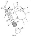
Figure 1 shows an exploded view of the gaseous fuel burner (including all mixtures thereof) with high energy efficiency, low pollutant emissions and greater heat transfer, with the teachings of the invention. -
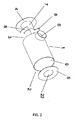
Figure 2 shows an exploded view of the housing of the gaseous fuel burner (including all mixtures thereof) pursuant tofigure 1 which shows the teachings of the invention. -
Figure 3 shows a perspective longitudinal cross-section of the gaseous fuel burner (including all mixtures thereof) without the end chamber for flame generation, with the teachings of the invention. -
Figure 4 shows a perspective longitudinal cross-section of the gaseous fuel burner (including all their mixtures thereof) incorporating the end chamber for flame generation, with the teachings of the invention. -
Figure 5 shows a cross-section of the gaseous fuel burner (including all mixtures thereof), completely assembled with the teachings of the invention. -
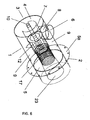
Figure 6 illustrates an isometric view of the gaseous fuel burner (including all mixtures thereof) pursuant to the invention, showing the inner chambers. - For a better understanding of the invention, we proceed to the detailed description of some embodiments thereof, shown in the drawings for illustrative purposes without limitation, attached to the description.
- The characteristic details of the gaseous fuel burner (including all mixtures thereof) with high energy and combustion efficiency, low pollutant emissions and greater heat transfer are clearly shown in the following description and in the attached illustrative drawings, which serve as reference highlight the same parts.
- Making reference to
figures 1 and4 , the burner consists of anouter housing 1 which defines adistal end 2 of outlet for the flame and aproximal end 3 of supply of the gaseous fuel (including all mixtures thereof) and oxidant (air); bothends having covers pressurized air inlet 6 is placed radially on the wall of the housing close to theproximal end 3, in which interior aconcave deflector 7 is placed in the zone of the inlet ofpressurized air 6 and is attached in saidcover 4 of theproximal end 3; at least twodeflector plates 8 separated between each other and radially fixed on the inner wall of saidhousing 1 and in saidconcave deflector 7; said deflectors allow a uniform distribution of the air in the interior of thehousing 1, defining a pressurized airsupply perimeter chamber 9. - The
cover 4 of theproximal end 3 is adapted to receive affixed in the center a pressurized gaseous fuel supply duct 10 (including all mixtures thereof) from a gaseous fuel supply source (including all mixtures thereof), which consists internally of a substantially cylindricalturbulence generating element 11 placed transversally which helps said gaseous fuel reach a turbulent flow (including all mixtures thereof); anend portion 10a of said gaseous fuel supply duct (including all mixtures thereof) housed in the interior of afirst mixing chamber 12 housed in the interior of saidhousing 1, which consists in acover 13 in its proximal end fixed to theconcave deflector 7 through which said gaseous fuel supply duct 10 (including all mixtures thereof) is centrally connected and is open in its distal end; saidend portion 10a of said gaseous fuel supply duct (including all mixtures thereof) is housed in the interior of said first mixingchamber 12 which includes a variety oforifices 14 in its wall for the outlet of the gaseous fuel (including all mixtures thereof) towards said first mixingchamber 12. - Said
cover 13 of the proximal end of said first mixingchamber 12, as well as its wall, include a variety oforifices 15 to supply pressurized air both radially axially and radially from said pressurized airsupply perimeter chamber 9, to generate a first turbulent enriched mixture of gaseous fuel (including all mixtures thereof) and air in said first mixingchamber 12; anigniter element 16 is placed in the proximal zone of said first mixingchamber 12 to generate a first stage of the combustion process in said first chamber. - The
orifices 14 of said gaseous fuel pressurized supply duct 10 (including all mixtures thereof) through which fuel is supplied to thefirst mixing chamber 12, are offset in relation to theorifices 15 of the wall of said first mixingchamber 12 through which the pressurized air is supplied from the pressurized airsupply perimeter chamber 9, to generate the maximum shearing force between both flows and achieve a better mixing. - A second over-mixing
open chamber 17 open in both ends, coupled collinearly with said first mixingchamber 12 through acoupling ring 18 staying housed within saidhousing 1, where the end of said gaseous fuel supply duct 10 (including all mixtures thereof) is placed centrally to the limit of the border between said first mixingchamber 12 and said secondover-mixing chamber 17; the distal end of said gaseous fuel supply duct 10 (including all mixtures thereof) consists of acone 10b which ends at theobstruction cover 19 with a variety oforifices 20 through which a turbulent flow of gaseous fuel (including all mixtures thereof) is supplied axially towards said secondover-mixing chamber 17 and the wall of said secondover-mixing chamber 17 consists of a variety oforifices 21 through which pressurized air is supplied radially from said pressurized airsupply perimeter chamber 9 to generate a second enriched, turbulent gaseous fuel (including all mixtures thereof) - air mixture and where a second stage of the combustion process takes place. - The dimensions of the second
over-mixing chamber 17 are smaller compared with thefirst mixing chamber 12. - Both mixing 12 and over-mixing 17 chambers have a particular arrangement of orifices which favor a highly turbulent mixture, as well as the complete oxidation of the fuel.
- The
cover 5 of the distal end of saidhousing 1 includes acentral opening 22 in which the secondover-mixing chamber 17, where the flame is generated, leads into. - A third conic chamber for the generation of the
flame 23 open at both ends (which is formed by the extension of the housing and a ceramic insulation conic body) is placed collinearly connected on the end of said secondover-mixing chamber 17, which provides the flame an adequate form to maximize the heat transfer. Thehousing 1 may extend to cover the outer end portion for said third chamber for the generation of theflame 23. - With reference to
figure 5 , it shows the different components of the burner in a longitudinal cross-section, illustrating the structural disposition and geometric arrangement in which the same numeric references for the same components that offer the benefits described above are expressed. This figure shows the gaseous fuel-air flow (including all mixtures thereof) to thefirst mixing chamber 12 and to the second over-mixingsecond chamber 17 and the passage of the flame generated by the combustion in the third chamber forflame generation 23, which provides the flame an adequate form to maximize heat transfer. - In
figure 6 shown, the same numerical references used to refer to the same components of the gaseous fuel burner (including all mixtures thereof) with the teachings of the invention are indicated. Additionally it is shown that saidhousing 1 includes also aflange 5a in the zone where thecover 5 of the distal end is affixed, to set the burner in a required zone. - This invention has been sufficiently described so a person with moderate knowledge in the art can reproduce and obtain the results outlined in this specification. Any person skilled in the technical field of this invention will be able to carry out modifications not outlined in this application, however, if the subject matter of the following claims is needed to perform these modifications in a determined structure or in the manufacture process thereof, said structures will be included in the scope of the invention.
Claims (19)
- A gaseous fuel burner with high energy and combustion efficiency, low pollutant emissions and greater heat transfer, characterized by consisting of an outer housing which defines a distal end for the outlet of the flame and a proximal end for the supply of the gaseous fuel (including all mixtures thereof) and air; both having covers; a pressurized air inlet is placed on the housing wall near the proximal end defining a inner pressurized air supply chamber; the cover of the proximal end receives affixed on the center a pressurized gaseous fuel supply duct (including all mixtures thereof), whose end portion is housed in the interior of a first mixing chamber placed in the interior of said housing, which includes a cover on its proximal end through which said fuel duct is connected and is open in its distal end; said end portion of said fuel duct includes a variety of orifices in its wall for the outlet of the gaseous fuel (including all mixtures thereof) towards said first mixing chamber; said cover of the proximal end of said first mixing chamber, as well as its wall include a variety of orifices to supply pressurized air axially and radially from said inner pressurized air supply chamber, to generate a first turbulent mixture of gaseous fuel (including all mixtures thereof) - air to the interior of said first mixing chamber; an igniter element is placed in the interior of said first mixing chamber to generate a first stage of the combustion process; a second over-mixing open chamber open in both ends, coupled collinearly with said first mixing chamber housed within said housing, where the end of said gaseous fuel supply duct (including all mixtures thereof) is placed centrally to the limit of the border between said first mixing chamber and said second over-mixing chamber; the end of said gaseous fuel supply duct (including all mixtures thereof) consists of an obstruction cover with a variety of orifices through which a turbulent flow of gaseous fuel (including all mixtures thereof) is supplied axially towards said second over-mixing chamber and the wall of said second over-mixing chamber consists of a variety of orifices through which pressurized air is supplied radially from said inner pressurized air supply perimeter chamber to generate a second enriched, turbulent gaseous fuel (including all mixtures thereof) - air mixture and where a second stage of the combustion process takes place; said cover of the distal end of said housing consists of a central opening in which said second chamber of over-mixing leads into.
- The gaseous fuel burner with high energy and combustion efficiency, low pollutant emissions and greater heat transfer, pursuant to claim 1 characterized because also includes a third conic chamber for the generation of the flame which is places collinearly connected on the end of said second over-mixing chamber, which provides the flame an adequate form to maximize the heat transfer.
- The gaseous fuel burner with high energy and combustion efficiency, low pollutant emissions and greater heat transfer, pursuant to claim 2 characterized because said third conic chamber for the generation of the flame consists of a wall with an angle between 7 and 9°.
- The gaseous fuel burner with high energy and combustion efficiency, low pollutant emissions and greater heat transfer, pursuant to claims 2 and 3, characterized because said housing extends until covering the outer end portion of said third chamber for the generation of the flame.
- The gaseous fuel burner with high energy and combustion efficiency, low pollutant emissions and greater heat transfer, pursuant to claim 1 characterized because towards the interior of the housing in the inlet of pressurized air, deflectors which allow the uniform distribution of the air in the interior of the inner pressurized air supply chamber are placed.
- The gaseous fuel burner with high energy and combustion efficiency, low pollutant emissions and greater heat transfer, pursuant to claim 5 characterized because said deflectors consists of a concave deflector placed in the inlet zone of pressurized air and affixed to the interior of said cover of the proximal end of the housing, and at least two deflector plates separated between each other and affixed radially in the inner wall of said housing and in said concave deflector; the distribution and arrangement of the deflectors allow an homogeneous flow of air in all the interior of said inner pressurized air supply chamber.
- The gaseous fuel burner with high energy and combustion efficiency, low pollutant emissions and greater heat transfer, pursuant to claim 1 characterized because said gaseous fuel supply duct (including all mixtures thereof) pressurized from a gaseous fuel supply source (including all mixtures thereof), consists in the interior of a turbulence generator element placed transversally which helps said gaseous fuel (including all mixtures thereof) to reach a turbulent flow.
- The gaseous fuel burner with high energy and combustion efficiency, low pollutant emissions and greater heat transfer, pursuant to claim 7 characterized because said turbulence generator element which is placed transversally in said gaseous fuel supply duct (including all mixtures thereof), may be of cylindrical or multi-faceted shape, either regular or irregular.
- The gaseous fuel burner with high energy and combustion efficiency, low pollutant emissions and greater heat transfer, pursuant to claims 1, 5 and 6, characterized because the distal end of said first mixing chamber is affixed in said concave deflector to remain centered within the housing.
- The gaseous fuel burner with high energy and combustion efficiency, low pollutant emissions and greater heat transfer, pursuant to claim 1 characterized because the orifices of said gaseous fuel pressurized supply duct (including all mixtures thereof) through which fuel is supplied to the first mixing chamber, are slightly offset in relation to the orifices of the wall of said first mixing chamber through which the pressurized air is supplied from the pressurized air supply perimeter chamber, to generate shearing forces between both flows and achieve a better mixing.
- The gaseous fuel burner with high energy and combustion efficiency, low pollutant emissions and greater heat transfer, pursuant to claim 1 characterized because said orifices both of the gaseous fuel supply duct (including all mixtures thereof) and of the wall of said first mixing chamber may have different shapes and sizes; be arranged in columns of equal or different number, at equal distance between each other or not, as well as in interspersed, offset or diagonal arrangements.
- The gaseous fuel burner with high energy and combustion efficiency, low pollutant emissions and greater heat transfer, pursuant to claim 1, characterized because the arrangement of said orifices of the cover of the proximal end of said mixing chamber through which pressurized air is supplied axially may be circular or polygonal, either regular or irregular or without a defined pattern.
- The gaseous fuel burner with high energy and combustion efficiency, low pollutant emissions and greater heat transfer, pursuant to claim 1 characterized because said orifices of the wall of said second over-mixing chamber may have different shapes and sizes; may be arranged in columns of equal or different number, at equal distance between each other or not, as well as in interspersed, offset or diagonal arrangements.
- The gaseous fuel burner with high energy and combustion efficiency, low pollutant emissions and greater heat transfer, pursuant to claim 1 characterized because said second over-mixing chamber open in both ends is coupled collinearly with said first mixing chamber through a coupling ring, being housed within said housing; the dimensions of said second over-mixing chamber are smaller than the first mixing chamber.
- The gaseous fuel burner with high energy and combustion efficiency, low pollutant emissions and greater heat transfer, pursuant to claim 1 characterized because the end portion of said gaseous fuel supply duct (including all mixtures thereof) has the shape of a funnel and is fitted with said obstruction cover with a variety of orifices through which a turbulent flow of gaseous fuel (including all mixtures thereof) is supplied axially towards said second over-mixing chamber.
- The gaseous fuel burner with high energy and combustion efficiency, low pollutant emissions and greater heat transfer, pursuant to claim 1, characterized because in said orifices of the wall of said second over-mixing chamber through which pressurized air is supplied from said pressurized air supply perimeter chamber defined by the housing, may be present speeds higher and lower than 10 m/s or Reynolds numbers higher or lower than 3,000 in laminar and turbulent flows, respectively; reaching a better performance in turbulent flow.
- The gaseous fuel burner with high energy and combustion efficiency, low pollutant emissions and greater heat transfer, pursuant to claim 1 characterized because handling laminar flows in both mixing and over-mixing chambers a turbulent flow is reached in said third conic chamber of flame generation, with speeds over 30 m/s and Reynolds numbers much greater than 30,000, reaching values in the order of 1,000,000 when the burner operates at full load.
- The gaseous fuel burner with high energy and combustion efficiency, low pollutant emissions and greater heat transfer, pursuant to the claims above, characterized because it handles up to 135% of excess air.
- The gaseous fuel burner with high energy and combustion efficiency, low pollutant emissions and greater heat transfer, pursuant to the claims above, characterized because it allows savings of gaseous fuels (including all mixtures thereof) of up to 50% and a reduction of pollutant emissions of up to 60%.
Applications Claiming Priority (2)
| Application Number | Priority Date | Filing Date | Title |
|---|---|---|---|
| MX2012006599A MX2012006599A (en) | 2012-06-08 | 2012-06-08 | Gaseous fuel burner with high energy and combustion efficiency, low pollutant emission and increased heat transfer. |
| PCT/MX2013/000061 WO2013183981A1 (en) | 2012-06-08 | 2013-05-14 | Gaseous fuel burner with high energy and combustion efficiency, low pollutant emission and increased heat transfer |
Publications (3)
| Publication Number | Publication Date |
|---|---|
| EP2871415A1 true EP2871415A1 (en) | 2015-05-13 |
| EP2871415A4 EP2871415A4 (en) | 2016-04-06 |
| EP2871415B1 EP2871415B1 (en) | 2019-03-13 |
Family
ID=49712307
Family Applications (1)
| Application Number | Title | Priority Date | Filing Date |
|---|---|---|---|
| EP13800226.6A Not-in-force EP2871415B1 (en) | 2012-06-08 | 2013-05-14 | Gaseous fuel burner with high energy and combustion efficiency, low pollutant emission and increased heat transfer |
Country Status (9)
| Country | Link |
|---|---|
| US (1) | US9879855B2 (en) |
| EP (1) | EP2871415B1 (en) |
| CN (1) | CN104508374B (en) |
| BR (1) | BR112014030599A2 (en) |
| CA (1) | CA2876065C (en) |
| CL (1) | CL2014003353A1 (en) |
| MX (1) | MX2012006599A (en) |
| RU (1) | RU2589587C1 (en) |
| WO (1) | WO2013183981A1 (en) |
Cited By (5)
| Publication number | Priority date | Publication date | Assignee | Title |
|---|---|---|---|---|
| EP3492812A3 (en) * | 2017-11-30 | 2019-08-21 | Brunswick Corporation | System and method for avoiding harmonic modes of gas burners |
| US11441772B2 (en) | 2018-07-19 | 2022-09-13 | Brunswick Corporation | Forced-draft pre-mix burner device |
| US11608983B2 (en) | 2020-12-02 | 2023-03-21 | Brunswick Corporation | Gas burner systems and methods for calibrating gas burner systems |
| US11940147B2 (en) | 2022-06-09 | 2024-03-26 | Brunswick Corporation | Blown air heating system |
| US12429217B2 (en) | 2022-06-09 | 2025-09-30 | Brunswick Corporation | Gas burner |
Families Citing this family (22)
| Publication number | Priority date | Publication date | Assignee | Title |
|---|---|---|---|---|
| US11041456B2 (en) | 2017-03-30 | 2021-06-22 | Quest Engines, LLC | Internal combustion engine |
| US10753308B2 (en) | 2017-03-30 | 2020-08-25 | Quest Engines, LLC | Internal combustion engine |
| US10465629B2 (en) | 2017-03-30 | 2019-11-05 | Quest Engines, LLC | Internal combustion engine having piston with deflector channels and complementary cylinder head |
| US10989138B2 (en) | 2017-03-30 | 2021-04-27 | Quest Engines, LLC | Internal combustion engine |
| US10590813B2 (en) | 2017-03-30 | 2020-03-17 | Quest Engines, LLC | Internal combustion engine |
| US10526953B2 (en) | 2017-03-30 | 2020-01-07 | Quest Engines, LLC | Internal combustion engine |
| US10598285B2 (en) | 2017-03-30 | 2020-03-24 | Quest Engines, LLC | Piston sealing system |
| US10590834B2 (en) | 2017-03-30 | 2020-03-17 | Quest Engines, LLC | Internal combustion engine |
| US10724428B2 (en) | 2017-04-28 | 2020-07-28 | Quest Engines, LLC | Variable volume chamber device |
| WO2018204684A1 (en) | 2017-05-04 | 2018-11-08 | Quest Engines, LLC | Variable volume chamber for interaction with a fluid |
| CN107461742B (en) * | 2017-08-09 | 2020-04-28 | 苏州博墨热能产品有限公司 | Graded flameless low-nitrogen combustion head |
| US10823402B2 (en) * | 2017-08-09 | 2020-11-03 | Haier Us Appliance Solutions, Inc. | Gas burner assembly for a cooktop appliance |
| US10655846B2 (en) * | 2017-09-18 | 2020-05-19 | Haier Us Appliance Solutions, Inc. | Gas burner assembly for a cooktop appliance |
| US11060636B2 (en) | 2017-09-29 | 2021-07-13 | Quest Engines, LLC | Engines and pumps with motionless one-way valve |
| WO2019147797A2 (en) | 2018-01-26 | 2019-08-01 | Quest Engines, LLC | Audio source waveguide |
| WO2019147963A1 (en) | 2018-01-26 | 2019-08-01 | Quest Engines, LLC | Method and apparatus for producing stratified streams |
| KR102755177B1 (en) * | 2018-04-26 | 2025-01-14 | 테크닙 에너지스 프랑스 | Burner system for steam cracking furnace |
| EP4063731A1 (en) * | 2021-03-24 | 2022-09-28 | Alfa Laval Corporate AB | Fluid burner head and use of fluid burner head |
| CN113217913B (en) * | 2021-05-12 | 2025-06-27 | 深圳三环科技有限公司 | A burner used in SOFC system |
| IT202100013535A1 (en) * | 2021-05-25 | 2022-11-25 | Sacmi Forni & Filter S P A | BURNER, APPARATUS AND METHOD FOR FIRING CERAMIC ARTIFACTS |
| CN116658897A (en) * | 2023-07-04 | 2023-08-29 | 上海全颉环境设备有限公司 | A multi-stage injection low-nitrogen combustion head |
| CN116817270B (en) * | 2023-08-30 | 2023-11-21 | 陕西华秦新能源科技有限责任公司 | Flame cutting's gas distribution device |
Family Cites Families (33)
| Publication number | Priority date | Publication date | Assignee | Title |
|---|---|---|---|---|
| US2806517A (en) * | 1950-11-16 | 1957-09-17 | Shell Dev | Oil atomizing double vortex burner |
| US3244219A (en) * | 1961-04-11 | 1966-04-05 | Midland Ross Corp | Self-stabilizing apparatus |
| US3408999A (en) * | 1967-05-04 | 1968-11-05 | American Air Filter Co | Liquid-fired cooking apparatus |
| US3947233A (en) * | 1971-04-26 | 1976-03-30 | C. A. Sundberg Ab | Free-burning equipment |
| US3861858A (en) * | 1972-12-11 | 1975-01-21 | Midland Ross Corp | Throat mix burner |
| US3951584A (en) | 1974-05-23 | 1976-04-20 | Midland-Ross Corporation | Self-stabilizing burner |
| US4030875A (en) * | 1975-12-22 | 1977-06-21 | General Electric Company | Integrated ceramic-metal combustor |
| JPS5939915A (en) * | 1982-08-27 | 1984-03-05 | Mazda Motor Corp | Exhaust gas purifying device for diesel engine |
| JPS5994110U (en) * | 1982-12-15 | 1984-06-26 | マツダ株式会社 | Diesel engine exhaust purification device |
| SU1158822A1 (en) * | 1983-06-30 | 1985-05-30 | Всесоюзный Научно-Исследовательский И Экспериментально-Конструкторский Институт Торгового Машиностроения | Air heater gas burner |
| JPS6057131A (en) * | 1983-09-08 | 1985-04-02 | Hitachi Ltd | Fuel feeding process for gas turbine combustor |
| US4671192A (en) * | 1984-06-29 | 1987-06-09 | Power Generating, Inc. | Pressurized cyclonic combustion method and burner for particulate solid fuels |
| GB2175684B (en) * | 1985-04-26 | 1989-12-28 | Nippon Kokan Kk | Burner |
| FR2589555B1 (en) * | 1985-11-06 | 1989-11-10 | Gaz De France | BLOW AIR GAS BURNER |
| IN170251B (en) * | 1987-04-16 | 1992-03-07 | Luminis Pty Ltd | |
| US4987738A (en) * | 1989-10-27 | 1991-01-29 | General Motors Corporation | Particulate trap system for an internal combustion engine |
| US5423675A (en) * | 1993-11-08 | 1995-06-13 | Kratsch; Kenneth | Burner mixing chamber |
| US5647739A (en) * | 1995-04-10 | 1997-07-15 | Eclipse, Inc. | Nozzle for use in a burner |
| US6026801A (en) * | 1996-04-30 | 2000-02-22 | Barkan; Kenneth C. | Plug core heat exchanger |
| DE19925875A1 (en) | 1999-06-07 | 2000-12-14 | Krupp Polysius Ag | Tubular burner for industrial furnaces |
| RU2216689C1 (en) * | 2002-07-29 | 2003-11-20 | Казанская государственная архитектурно-строительная академия | Burning facility |
| US6918757B2 (en) * | 2002-08-29 | 2005-07-19 | Noritz Corporation | Combustion apparatus |
| RU2230256C1 (en) * | 2002-12-05 | 2004-06-10 | Курносов Владимир Владимирович | Method of heating air by spray cone and device for realization of this method |
| ITMI20032327A1 (en) | 2003-11-28 | 2005-05-29 | Techint Spa | GAS BURNER WITH LOW POLLUTING EMISSIONS. |
| JP2005226847A (en) * | 2004-02-10 | 2005-08-25 | Ebara Corp | Combustion device and method |
| US7785100B1 (en) | 2004-10-01 | 2010-08-31 | Malcolm Swanson | Burner assembly with turbulent tube fuel-air mixer |
| JP4894295B2 (en) * | 2006-02-28 | 2012-03-14 | 株式会社日立製作所 | Combustion device, combustion method of combustion device, and modification method of combustion device |
| FR2903762B1 (en) | 2006-07-13 | 2008-09-05 | Air Liquide | BURNER AND METHOD FOR ALTERNATING OXYCOMBUSTION AND AEROCOMBUSTION |
| DE102008055981A1 (en) * | 2008-11-05 | 2010-05-06 | Owi Oel-Waerme-Institut Ggmbh | Method for reducing pollutant emissions e.g. carbon-monoxide emissions, of surface burner in combustion system, involves arranging or folding burner surface such that fluid is partially or completely passed through porous surfaces |
| ITMO20080329A1 (en) * | 2008-12-23 | 2010-06-24 | Tck S R L | COMBUSTION HEAD AND BURNER INCLUDING THIS HEAD. |
| US20110225973A1 (en) * | 2010-03-18 | 2011-09-22 | General Electric Company | Combustor with Pre-Mixing Primary Fuel-Nozzle Assembly |
| EP2551588B1 (en) * | 2010-03-24 | 2019-01-30 | IHI Corporation | Burner device |
| US20110223549A1 (en) * | 2010-05-31 | 2011-09-15 | Resource Rex, LLC | Laminar Flow Combustion System and Method for Enhancing Combustion Efficiency |
-
2012
- 2012-06-08 MX MX2012006599A patent/MX2012006599A/en unknown
-
2013
- 2013-05-14 WO PCT/MX2013/000061 patent/WO2013183981A1/en not_active Ceased
- 2013-05-14 US US14/406,478 patent/US9879855B2/en active Active
- 2013-05-14 EP EP13800226.6A patent/EP2871415B1/en not_active Not-in-force
- 2013-05-14 CN CN201380039717.0A patent/CN104508374B/en not_active Expired - Fee Related
- 2013-05-14 CA CA2876065A patent/CA2876065C/en active Active
- 2013-05-14 BR BR112014030599A patent/BR112014030599A2/en not_active Application Discontinuation
- 2013-05-14 RU RU2014152912/06A patent/RU2589587C1/en active IP Right Revival
-
2014
- 2014-12-09 CL CL2014003353A patent/CL2014003353A1/en unknown
Cited By (8)
| Publication number | Priority date | Publication date | Assignee | Title |
|---|---|---|---|---|
| EP3492812A3 (en) * | 2017-11-30 | 2019-08-21 | Brunswick Corporation | System and method for avoiding harmonic modes of gas burners |
| US10718518B2 (en) | 2017-11-30 | 2020-07-21 | Brunswick Corporation | Systems and methods for avoiding harmonic modes of gas burners |
| EP3757456A1 (en) * | 2017-11-30 | 2020-12-30 | Brunswick Corporation | System and method for avoiding harmonic modes of gas burners |
| US11608984B1 (en) | 2017-11-30 | 2023-03-21 | Brunswick Corporation | Systems for avoiding harmonic modes of gas burners |
| US11441772B2 (en) | 2018-07-19 | 2022-09-13 | Brunswick Corporation | Forced-draft pre-mix burner device |
| US11608983B2 (en) | 2020-12-02 | 2023-03-21 | Brunswick Corporation | Gas burner systems and methods for calibrating gas burner systems |
| US11940147B2 (en) | 2022-06-09 | 2024-03-26 | Brunswick Corporation | Blown air heating system |
| US12429217B2 (en) | 2022-06-09 | 2025-09-30 | Brunswick Corporation | Gas burner |
Also Published As
| Publication number | Publication date |
|---|---|
| CA2876065C (en) | 2018-12-18 |
| CL2014003353A1 (en) | 2015-06-19 |
| US20150153040A1 (en) | 2015-06-04 |
| WO2013183981A1 (en) | 2013-12-12 |
| US9879855B2 (en) | 2018-01-30 |
| MX2012006599A (en) | 2013-12-16 |
| RU2589587C1 (en) | 2016-07-10 |
| EP2871415A4 (en) | 2016-04-06 |
| CN104508374B (en) | 2017-03-29 |
| EP2871415B1 (en) | 2019-03-13 |
| CA2876065A1 (en) | 2013-12-12 |
| BR112014030599A2 (en) | 2017-06-27 |
| CN104508374A (en) | 2015-04-08 |
Similar Documents
| Publication | Publication Date | Title |
|---|---|---|
| EP2871415B1 (en) | Gaseous fuel burner with high energy and combustion efficiency, low pollutant emission and increased heat transfer | |
| JP4309380B2 (en) | Multistage combustion system with ignition assisted fuel lance | |
| WO2004094907A1 (en) | Partially-open fired heater cycle providing high thermal efficiencies and ultra-low emissions | |
| WO2010129739A1 (en) | Apparatus and methods for providing uniformly volume distributed combustion of fuel | |
| US20120308943A1 (en) | Energy-saving method for gas combustion and burner thereof | |
| JP2524025B2 (en) | Low calorie gas combustion burner structure and its combustion method | |
| CN201066122Y (en) | Infrared burner | |
| CN201014444Y (en) | CBM burner | |
| CN102798129B (en) | Efficient thermal oxidation furnace for low afterburning-amount smoke constant-speed grading reaction | |
| CN201462843U (en) | combustor | |
| EP3597999B1 (en) | Gas water heater and burner thereof | |
| CN202813398U (en) | Low complementary combustion volume flue gas constant-speed fractional reaction efficient thermal oxidation furnace | |
| CN207648854U (en) | A kind of soft homogeneous catalysis burner | |
| CN211952747U (en) | Premixing unit and combustor | |
| CN203385195U (en) | Porous medium flue gas hot blast stove capable of mixing cold air | |
| CN202902296U (en) | Semi-premixed high-efficiency burner | |
| RU2454605C1 (en) | Technological vortex ejection gas burner | |
| Pathan et al. | Numerical investigation of the combustion of methane air mixture in gas turbine can-type combustion chamber | |
| Abdulrahman et al. | A review of liquid fuel flameless combustion with various flow configurations | |
| CN205332211U (en) | Woven wire bars low NOx burner | |
| CN119267956B (en) | Micro-mixing single nozzle, combustor and gas turbine | |
| CN115560323B (en) | Burner and gas water heater | |
| RU2361150C1 (en) | Mixing gas heat generator | |
| RU26108U1 (en) | GAS-BURNER | |
| Abdulrahman et al. | Thermal and Emissions Characteristics of Liquid Fuel Flameless Combustion in a Forward Flow Combustion Chamber |
Legal Events
| Date | Code | Title | Description |
|---|---|---|---|
| PUAI | Public reference made under article 153(3) epc to a published international application that has entered the european phase |
Free format text: ORIGINAL CODE: 0009012 |
|
| 17P | Request for examination filed |
Effective date: 20141212 |
|
| AK | Designated contracting states |
Kind code of ref document: A1 Designated state(s): AL AT BE BG CH CY CZ DE DK EE ES FI FR GB GR HR HU IE IS IT LI LT LU LV MC MK MT NL NO PL PT RO RS SE SI SK SM TR |
|
| AX | Request for extension of the european patent |
Extension state: BA ME |
|
| DAX | Request for extension of the european patent (deleted) | ||
| RA4 | Supplementary search report drawn up and despatched (corrected) |
Effective date: 20160309 |
|
| RIC1 | Information provided on ipc code assigned before grant |
Ipc: F23D 14/62 20060101ALI20160303BHEP Ipc: F23D 14/22 20060101AFI20160303BHEP Ipc: F23D 14/58 20060101ALI20160303BHEP |
|
| STAA | Information on the status of an ep patent application or granted ep patent |
Free format text: STATUS: EXAMINATION IS IN PROGRESS |
|
| 17Q | First examination report despatched |
Effective date: 20170411 |
|
| GRAP | Despatch of communication of intention to grant a patent |
Free format text: ORIGINAL CODE: EPIDOSNIGR1 |
|
| STAA | Information on the status of an ep patent application or granted ep patent |
Free format text: STATUS: GRANT OF PATENT IS INTENDED |
|
| INTG | Intention to grant announced |
Effective date: 20180928 |
|
| GRAS | Grant fee paid |
Free format text: ORIGINAL CODE: EPIDOSNIGR3 |
|
| GRAA | (expected) grant |
Free format text: ORIGINAL CODE: 0009210 |
|
| STAA | Information on the status of an ep patent application or granted ep patent |
Free format text: STATUS: THE PATENT HAS BEEN GRANTED |
|
| AK | Designated contracting states |
Kind code of ref document: B1 Designated state(s): AL AT BE BG CH CY CZ DE DK EE ES FI FR GB GR HR HU IE IS IT LI LT LU LV MC MK MT NL NO PL PT RO RS SE SI SK SM TR |
|
| REG | Reference to a national code |
Ref country code: GB Ref legal event code: FG4D |
|
| REG | Reference to a national code |
Ref country code: CH Ref legal event code: EP Ref country code: AT Ref legal event code: REF Ref document number: 1108214 Country of ref document: AT Kind code of ref document: T Effective date: 20190315 |
|
| REG | Reference to a national code |
Ref country code: IE Ref legal event code: FG4D |
|
| REG | Reference to a national code |
Ref country code: DE Ref legal event code: R096 Ref document number: 602013052374 Country of ref document: DE |
|
| PGFP | Annual fee paid to national office [announced via postgrant information from national office to epo] |
Ref country code: FR Payment date: 20190313 Year of fee payment: 7 Ref country code: IE Payment date: 20190315 Year of fee payment: 7 Ref country code: MC Payment date: 20190322 Year of fee payment: 7 Ref country code: LU Payment date: 20190315 Year of fee payment: 7 |
|
| REG | Reference to a national code |
Ref country code: NL Ref legal event code: MP Effective date: 20190313 |
|
| REG | Reference to a national code |
Ref country code: LT Ref legal event code: MG4D |
|
| PG25 | Lapsed in a contracting state [announced via postgrant information from national office to epo] |
Ref country code: SE Free format text: LAPSE BECAUSE OF FAILURE TO SUBMIT A TRANSLATION OF THE DESCRIPTION OR TO PAY THE FEE WITHIN THE PRESCRIBED TIME-LIMIT Effective date: 20190313 Ref country code: FI Free format text: LAPSE BECAUSE OF FAILURE TO SUBMIT A TRANSLATION OF THE DESCRIPTION OR TO PAY THE FEE WITHIN THE PRESCRIBED TIME-LIMIT Effective date: 20190313 Ref country code: NO Free format text: LAPSE BECAUSE OF FAILURE TO SUBMIT A TRANSLATION OF THE DESCRIPTION OR TO PAY THE FEE WITHIN THE PRESCRIBED TIME-LIMIT Effective date: 20190613 Ref country code: LT Free format text: LAPSE BECAUSE OF FAILURE TO SUBMIT A TRANSLATION OF THE DESCRIPTION OR TO PAY THE FEE WITHIN THE PRESCRIBED TIME-LIMIT Effective date: 20190313 |
|
| PG25 | Lapsed in a contracting state [announced via postgrant information from national office to epo] |
Ref country code: HR Free format text: LAPSE BECAUSE OF FAILURE TO SUBMIT A TRANSLATION OF THE DESCRIPTION OR TO PAY THE FEE WITHIN THE PRESCRIBED TIME-LIMIT Effective date: 20190313 Ref country code: GR Free format text: LAPSE BECAUSE OF FAILURE TO SUBMIT A TRANSLATION OF THE DESCRIPTION OR TO PAY THE FEE WITHIN THE PRESCRIBED TIME-LIMIT Effective date: 20190614 Ref country code: NL Free format text: LAPSE BECAUSE OF FAILURE TO SUBMIT A TRANSLATION OF THE DESCRIPTION OR TO PAY THE FEE WITHIN THE PRESCRIBED TIME-LIMIT Effective date: 20190313 Ref country code: LV Free format text: LAPSE BECAUSE OF FAILURE TO SUBMIT A TRANSLATION OF THE DESCRIPTION OR TO PAY THE FEE WITHIN THE PRESCRIBED TIME-LIMIT Effective date: 20190313 Ref country code: BG Free format text: LAPSE BECAUSE OF FAILURE TO SUBMIT A TRANSLATION OF THE DESCRIPTION OR TO PAY THE FEE WITHIN THE PRESCRIBED TIME-LIMIT Effective date: 20190613 Ref country code: RS Free format text: LAPSE BECAUSE OF FAILURE TO SUBMIT A TRANSLATION OF THE DESCRIPTION OR TO PAY THE FEE WITHIN THE PRESCRIBED TIME-LIMIT Effective date: 20190313 |
|
| REG | Reference to a national code |
Ref country code: AT Ref legal event code: MK05 Ref document number: 1108214 Country of ref document: AT Kind code of ref document: T Effective date: 20190313 |
|
| PGFP | Annual fee paid to national office [announced via postgrant information from national office to epo] |
Ref country code: CH Payment date: 20190403 Year of fee payment: 7 |
|
| PG25 | Lapsed in a contracting state [announced via postgrant information from national office to epo] |
Ref country code: SK Free format text: LAPSE BECAUSE OF FAILURE TO SUBMIT A TRANSLATION OF THE DESCRIPTION OR TO PAY THE FEE WITHIN THE PRESCRIBED TIME-LIMIT Effective date: 20190313 Ref country code: RO Free format text: LAPSE BECAUSE OF FAILURE TO SUBMIT A TRANSLATION OF THE DESCRIPTION OR TO PAY THE FEE WITHIN THE PRESCRIBED TIME-LIMIT Effective date: 20190313 Ref country code: IT Free format text: LAPSE BECAUSE OF FAILURE TO SUBMIT A TRANSLATION OF THE DESCRIPTION OR TO PAY THE FEE WITHIN THE PRESCRIBED TIME-LIMIT Effective date: 20190313 Ref country code: EE Free format text: LAPSE BECAUSE OF FAILURE TO SUBMIT A TRANSLATION OF THE DESCRIPTION OR TO PAY THE FEE WITHIN THE PRESCRIBED TIME-LIMIT Effective date: 20190313 Ref country code: CZ Free format text: LAPSE BECAUSE OF FAILURE TO SUBMIT A TRANSLATION OF THE DESCRIPTION OR TO PAY THE FEE WITHIN THE PRESCRIBED TIME-LIMIT Effective date: 20190313 Ref country code: PT Free format text: LAPSE BECAUSE OF FAILURE TO SUBMIT A TRANSLATION OF THE DESCRIPTION OR TO PAY THE FEE WITHIN THE PRESCRIBED TIME-LIMIT Effective date: 20190713 Ref country code: AL Free format text: LAPSE BECAUSE OF FAILURE TO SUBMIT A TRANSLATION OF THE DESCRIPTION OR TO PAY THE FEE WITHIN THE PRESCRIBED TIME-LIMIT Effective date: 20190313 Ref country code: ES Free format text: LAPSE BECAUSE OF FAILURE TO SUBMIT A TRANSLATION OF THE DESCRIPTION OR TO PAY THE FEE WITHIN THE PRESCRIBED TIME-LIMIT Effective date: 20190313 |
|
| PG25 | Lapsed in a contracting state [announced via postgrant information from national office to epo] |
Ref country code: PL Free format text: LAPSE BECAUSE OF FAILURE TO SUBMIT A TRANSLATION OF THE DESCRIPTION OR TO PAY THE FEE WITHIN THE PRESCRIBED TIME-LIMIT Effective date: 20190313 Ref country code: SM Free format text: LAPSE BECAUSE OF FAILURE TO SUBMIT A TRANSLATION OF THE DESCRIPTION OR TO PAY THE FEE WITHIN THE PRESCRIBED TIME-LIMIT Effective date: 20190313 |
|
| REG | Reference to a national code |
Ref country code: DE Ref legal event code: R097 Ref document number: 602013052374 Country of ref document: DE |
|
| PG25 | Lapsed in a contracting state [announced via postgrant information from national office to epo] |
Ref country code: AT Free format text: LAPSE BECAUSE OF FAILURE TO SUBMIT A TRANSLATION OF THE DESCRIPTION OR TO PAY THE FEE WITHIN THE PRESCRIBED TIME-LIMIT Effective date: 20190313 Ref country code: IS Free format text: LAPSE BECAUSE OF FAILURE TO SUBMIT A TRANSLATION OF THE DESCRIPTION OR TO PAY THE FEE WITHIN THE PRESCRIBED TIME-LIMIT Effective date: 20190713 |
|
| PLBE | No opposition filed within time limit |
Free format text: ORIGINAL CODE: 0009261 |
|
| STAA | Information on the status of an ep patent application or granted ep patent |
Free format text: STATUS: NO OPPOSITION FILED WITHIN TIME LIMIT |
|
| PG25 | Lapsed in a contracting state [announced via postgrant information from national office to epo] |
Ref country code: DK Free format text: LAPSE BECAUSE OF FAILURE TO SUBMIT A TRANSLATION OF THE DESCRIPTION OR TO PAY THE FEE WITHIN THE PRESCRIBED TIME-LIMIT Effective date: 20190313 |
|
| REG | Reference to a national code |
Ref country code: BE Ref legal event code: MM Effective date: 20190531 |
|
| 26N | No opposition filed |
Effective date: 20191216 |
|
| PG25 | Lapsed in a contracting state [announced via postgrant information from national office to epo] |
Ref country code: SI Free format text: LAPSE BECAUSE OF FAILURE TO SUBMIT A TRANSLATION OF THE DESCRIPTION OR TO PAY THE FEE WITHIN THE PRESCRIBED TIME-LIMIT Effective date: 20190313 |
|
| PG25 | Lapsed in a contracting state [announced via postgrant information from national office to epo] |
Ref country code: TR Free format text: LAPSE BECAUSE OF FAILURE TO SUBMIT A TRANSLATION OF THE DESCRIPTION OR TO PAY THE FEE WITHIN THE PRESCRIBED TIME-LIMIT Effective date: 20190313 |
|
| PG25 | Lapsed in a contracting state [announced via postgrant information from national office to epo] |
Ref country code: BE Free format text: LAPSE BECAUSE OF NON-PAYMENT OF DUE FEES Effective date: 20190531 |
|
| PGFP | Annual fee paid to national office [announced via postgrant information from national office to epo] |
Ref country code: GB Payment date: 20200428 Year of fee payment: 8 |
|
| PG25 | Lapsed in a contracting state [announced via postgrant information from national office to epo] |
Ref country code: LI Free format text: LAPSE BECAUSE OF NON-PAYMENT OF DUE FEES Effective date: 20200531 Ref country code: CH Free format text: LAPSE BECAUSE OF NON-PAYMENT OF DUE FEES Effective date: 20200531 Ref country code: MC Free format text: LAPSE BECAUSE OF NON-PAYMENT OF DUE FEES Effective date: 20200602 |
|
| PG25 | Lapsed in a contracting state [announced via postgrant information from national office to epo] |
Ref country code: LU Free format text: LAPSE BECAUSE OF NON-PAYMENT OF DUE FEES Effective date: 20200514 |
|
| PG25 | Lapsed in a contracting state [announced via postgrant information from national office to epo] |
Ref country code: IE Free format text: LAPSE BECAUSE OF NON-PAYMENT OF DUE FEES Effective date: 20200514 Ref country code: FR Free format text: LAPSE BECAUSE OF NON-PAYMENT OF DUE FEES Effective date: 20200531 |
|
| PG25 | Lapsed in a contracting state [announced via postgrant information from national office to epo] |
Ref country code: CY Free format text: LAPSE BECAUSE OF FAILURE TO SUBMIT A TRANSLATION OF THE DESCRIPTION OR TO PAY THE FEE WITHIN THE PRESCRIBED TIME-LIMIT Effective date: 20190313 |
|
| PG25 | Lapsed in a contracting state [announced via postgrant information from national office to epo] |
Ref country code: MT Free format text: LAPSE BECAUSE OF FAILURE TO SUBMIT A TRANSLATION OF THE DESCRIPTION OR TO PAY THE FEE WITHIN THE PRESCRIBED TIME-LIMIT Effective date: 20190313 Ref country code: HU Free format text: LAPSE BECAUSE OF FAILURE TO SUBMIT A TRANSLATION OF THE DESCRIPTION OR TO PAY THE FEE WITHIN THE PRESCRIBED TIME-LIMIT; INVALID AB INITIO Effective date: 20130514 |
|
| GBPC | Gb: european patent ceased through non-payment of renewal fee |
Effective date: 20210514 |
|
| PG25 | Lapsed in a contracting state [announced via postgrant information from national office to epo] |
Ref country code: GB Free format text: LAPSE BECAUSE OF NON-PAYMENT OF DUE FEES Effective date: 20210514 |
|
| PG25 | Lapsed in a contracting state [announced via postgrant information from national office to epo] |
Ref country code: MK Free format text: LAPSE BECAUSE OF FAILURE TO SUBMIT A TRANSLATION OF THE DESCRIPTION OR TO PAY THE FEE WITHIN THE PRESCRIBED TIME-LIMIT Effective date: 20190313 |
|
| PGFP | Annual fee paid to national office [announced via postgrant information from national office to epo] |
Ref country code: DE Payment date: 20231129 Year of fee payment: 11 |
|
| REG | Reference to a national code |
Ref country code: DE Ref legal event code: R119 Ref document number: 602013052374 Country of ref document: DE |
|
| PG25 | Lapsed in a contracting state [announced via postgrant information from national office to epo] |
Ref country code: DE Free format text: LAPSE BECAUSE OF NON-PAYMENT OF DUE FEES Effective date: 20241203 |