EP2871367A1 - Roots-style blower with leakage mechanisms - Google Patents
Roots-style blower with leakage mechanisms Download PDFInfo
- Publication number
- EP2871367A1 EP2871367A1 EP20130192052 EP13192052A EP2871367A1 EP 2871367 A1 EP2871367 A1 EP 2871367A1 EP 20130192052 EP20130192052 EP 20130192052 EP 13192052 A EP13192052 A EP 13192052A EP 2871367 A1 EP2871367 A1 EP 2871367A1
- Authority
- EP
- European Patent Office
- Prior art keywords
- roots
- type blower
- lobe
- end wall
- housing
- Prior art date
- Legal status (The legal status is an assumption and is not a legal conclusion. Google has not performed a legal analysis and makes no representation as to the accuracy of the status listed.)
- Granted
Links
Images




Classifications
-
- F—MECHANICAL ENGINEERING; LIGHTING; HEATING; WEAPONS; BLASTING
- F04—POSITIVE - DISPLACEMENT MACHINES FOR LIQUIDS; PUMPS FOR LIQUIDS OR ELASTIC FLUIDS
- F04C—ROTARY-PISTON, OR OSCILLATING-PISTON, POSITIVE-DISPLACEMENT MACHINES FOR LIQUIDS; ROTARY-PISTON, OR OSCILLATING-PISTON, POSITIVE-DISPLACEMENT PUMPS
- F04C29/00—Component parts, details or accessories of pumps or pumping installations, not provided for in groups F04C18/00 - F04C28/00
- F04C29/06—Silencing
- F04C29/065—Noise dampening volumes, e.g. muffler chambers
-
- F—MECHANICAL ENGINEERING; LIGHTING; HEATING; WEAPONS; BLASTING
- F04—POSITIVE - DISPLACEMENT MACHINES FOR LIQUIDS; PUMPS FOR LIQUIDS OR ELASTIC FLUIDS
- F04C—ROTARY-PISTON, OR OSCILLATING-PISTON, POSITIVE-DISPLACEMENT MACHINES FOR LIQUIDS; ROTARY-PISTON, OR OSCILLATING-PISTON, POSITIVE-DISPLACEMENT PUMPS
- F04C15/00—Component parts, details or accessories of machines, pumps or pumping installations, not provided for in groups F04C2/00 - F04C14/00
- F04C15/0003—Sealing arrangements in rotary-piston machines or pumps
- F04C15/0023—Axial sealings for working fluid
- F04C15/0026—Elements specially adapted for sealing of the lateral faces of intermeshing-engagement type machines or pumps, e.g. gear machines or pumps
-
- F—MECHANICAL ENGINEERING; LIGHTING; HEATING; WEAPONS; BLASTING
- F04—POSITIVE - DISPLACEMENT MACHINES FOR LIQUIDS; PUMPS FOR LIQUIDS OR ELASTIC FLUIDS
- F04C—ROTARY-PISTON, OR OSCILLATING-PISTON, POSITIVE-DISPLACEMENT MACHINES FOR LIQUIDS; ROTARY-PISTON, OR OSCILLATING-PISTON, POSITIVE-DISPLACEMENT PUMPS
- F04C15/00—Component parts, details or accessories of machines, pumps or pumping installations, not provided for in groups F04C2/00 - F04C14/00
- F04C15/0042—Systems for the equilibration of forces acting on the machines or pump
- F04C15/0049—Equalization of pressure pulses
-
- F—MECHANICAL ENGINEERING; LIGHTING; HEATING; WEAPONS; BLASTING
- F04—POSITIVE - DISPLACEMENT MACHINES FOR LIQUIDS; PUMPS FOR LIQUIDS OR ELASTIC FLUIDS
- F04C—ROTARY-PISTON, OR OSCILLATING-PISTON, POSITIVE-DISPLACEMENT MACHINES FOR LIQUIDS; ROTARY-PISTON, OR OSCILLATING-PISTON, POSITIVE-DISPLACEMENT PUMPS
- F04C15/00—Component parts, details or accessories of machines, pumps or pumping installations, not provided for in groups F04C2/00 - F04C14/00
- F04C15/06—Arrangements for admission or discharge of the working fluid, e.g. constructional features of the inlet or outlet
-
- F—MECHANICAL ENGINEERING; LIGHTING; HEATING; WEAPONS; BLASTING
- F04—POSITIVE - DISPLACEMENT MACHINES FOR LIQUIDS; PUMPS FOR LIQUIDS OR ELASTIC FLUIDS
- F04C—ROTARY-PISTON, OR OSCILLATING-PISTON, POSITIVE-DISPLACEMENT MACHINES FOR LIQUIDS; ROTARY-PISTON, OR OSCILLATING-PISTON, POSITIVE-DISPLACEMENT PUMPS
- F04C18/00—Rotary-piston pumps specially adapted for elastic fluids
- F04C18/08—Rotary-piston pumps specially adapted for elastic fluids of intermeshing-engagement type, i.e. with engagement of co-operating members similar to that of toothed gearing
- F04C18/10—Rotary-piston pumps specially adapted for elastic fluids of intermeshing-engagement type, i.e. with engagement of co-operating members similar to that of toothed gearing of internal-axis type with the outer member having more teeth or tooth equivalents, e.g. rollers, than the inner member
- F04C18/107—Rotary-piston pumps specially adapted for elastic fluids of intermeshing-engagement type, i.e. with engagement of co-operating members similar to that of toothed gearing of internal-axis type with the outer member having more teeth or tooth equivalents, e.g. rollers, than the inner member with helical teeth
-
- F—MECHANICAL ENGINEERING; LIGHTING; HEATING; WEAPONS; BLASTING
- F04—POSITIVE - DISPLACEMENT MACHINES FOR LIQUIDS; PUMPS FOR LIQUIDS OR ELASTIC FLUIDS
- F04C—ROTARY-PISTON, OR OSCILLATING-PISTON, POSITIVE-DISPLACEMENT MACHINES FOR LIQUIDS; ROTARY-PISTON, OR OSCILLATING-PISTON, POSITIVE-DISPLACEMENT PUMPS
- F04C18/00—Rotary-piston pumps specially adapted for elastic fluids
- F04C18/08—Rotary-piston pumps specially adapted for elastic fluids of intermeshing-engagement type, i.e. with engagement of co-operating members similar to that of toothed gearing
- F04C18/12—Rotary-piston pumps specially adapted for elastic fluids of intermeshing-engagement type, i.e. with engagement of co-operating members similar to that of toothed gearing of other than internal-axis type
- F04C18/126—Rotary-piston pumps specially adapted for elastic fluids of intermeshing-engagement type, i.e. with engagement of co-operating members similar to that of toothed gearing of other than internal-axis type with radially from the rotor body extending elements, not necessarily co-operating with corresponding recesses in the other rotor, e.g. lobes, Roots type
-
- F—MECHANICAL ENGINEERING; LIGHTING; HEATING; WEAPONS; BLASTING
- F04—POSITIVE - DISPLACEMENT MACHINES FOR LIQUIDS; PUMPS FOR LIQUIDS OR ELASTIC FLUIDS
- F04C—ROTARY-PISTON, OR OSCILLATING-PISTON, POSITIVE-DISPLACEMENT MACHINES FOR LIQUIDS; ROTARY-PISTON, OR OSCILLATING-PISTON, POSITIVE-DISPLACEMENT PUMPS
- F04C29/00—Component parts, details or accessories of pumps or pumping installations, not provided for in groups F04C18/00 - F04C28/00
- F04C29/12—Arrangements for admission or discharge of the working fluid, e.g. constructional features of the inlet or outlet
- F04C29/122—Arrangements for supercharging the working space
Definitions
- This invention relates to Roots-type blowers and more particularly to such blowers in which the lobes are twisted.
- Roots-type blowers are commonly used for pumping volumes of air in applications such as boosting or supercharging internal combustion engines of vehicles.
- Roots-type blower superchargers are used for transferring volumes of air into the combustion chambers of an engine.
- the transferred volumes of air are greater than the displacement of the engine, thereby increasing the air pressure within the combustion chambers which results in greater engine output power.
- a Roots-type blower is a positive displacement lobe pump which operates by pumping a fluid with a pair of meshing, lobed rotors provided in overlapping rotor chambers. Fluid is trapped in pockets surrounding the lobes and carried from the intake side to an outlet side.
- Roots-type blowers typically have twisted lobes, i.e. the rotor lobes define a helix angle greater than zero relative to the axial direction of the rotor.
- Another significant parameter in a Roots-type blower is the twist angle of each lobe, i.e. the angular displacement in degrees when travelling along a lobe from one end of the rotor to the other end of the rotor.
- Roots-type blowers generate high levels of pulsation noise.
- the noise can be reduced by increasing the helix angle of the lobes.
- a large helix angle results in many "blowholes" being formed in connection with meshing of the lobes as the rotors rotate.
- the blowholes permit communication between adjacent pockets of fluid, which allows for pressure equalization prior to opening the outlet port. Pressure equalization is known to reduce air turbulence (pulsation) and hence pulsation noise.
- Roots-type blower Even with many blowholes a Roots-type blower still may produce a considerable amount of noise. Especially, a Roots-type blower may cause a lot of nuisance in a vehicle if run hard at low engine speeds, as the engine at low speeds does not produce sufficient noise to drown the noise from the Roots-type blower.
- An object of the present invention is to provide a Roots-type blower having a reduced level of NVH (Noise Vibration Harshness). This object is achieved by the features of claim 1 and 10.
- the invention concerns a roots-type blower.
- the blower comprising a housing defining first and second transversely overlapping cylindrical chambers, and the housing comprising a first end wall and a second end wall.
- the housing defining at least one inlet port adjacent said first end wall and at least one outlet port adjacent said second end wall.
- the blower further comprises first and second meshed, lobed rotors disposed, respectively, in said first and second cylindrical chambers.
- Each rotor includes a plurality of lobes. Each lobe having first and second axially facing end surfaces sealingly cooperating with said first and second end walls, respectively, and a top land sealingly cooperating with said cylindrical chambers.
- the blower further comprises a plurality of control volumes for transfer of fluid from the at least one inlet port to the at least one outlet port.
- Each control volume being defined by a pair of adjacent lobes on one of the rotors, and at least one of the cylindrical chambers, first end wall, and/or second end wall.
- the blower also has a leakage mechanism for effecting a leakage of fluid between adjacent control volumes.
- the leakage mechanism including blowholes formed within the cylindrical chambers in connection with meshing of the lobes of the first and second rotors.
- Roots-type blower comprises an additional leakage mechanism in form of at least one backflow slot extending through the housing wall of each cylindrical chamber for effecting a leakage of fluid from downstream the at least one outlet port into a control volume prior to traversal of the at least one outlet port boundaries by the top land of the lead lobe of said control volume.
- Roots-type blowers having blowholes as leakage mechanism provides a certain level of pressure equalisation between adjacent control volumes prior to opening to the outlet port.
- Roots-type blowers having blowholes as their only leakage mechanism suffer from insufficient pressure equalisation. The insufficient pressure equalisation occurs even when a relatively high twist angle is used, e.g.
- an increased twist angle results in increased internal leakage for several reasons.
- an increased number of blowholes are generally present simultaneously in the blower, the existence of each blow hole over time is prolonged, and since the axial air speed within each control volume is reduced there is less likelihood of generating a vacuum at the inlet port, such that increased air pressure within each control volume and reduced turbulence is enabled.
- the advantage of providing at least one additional leakage mechanism according to the invention is further improved pressure equalisation between adjacent control volumes prior to opening to the outlet port, such that the NVH level generated by the Roots-type blower is further reduced.
- the Roots-type blower comprises a leakage mechanism for effecting a leakage of fluid between adjacent control volumes, wherein said leakage mechanism comprises at least one bleed recess provided in the second end wall, and wherein said bleed recess provides a passage between the second axially facing end surface of a lobe and the second end wall such that fluid is enabled to leak between adjacent control volumes.
- This solution which is technically different but exhibiting essentially the same technical effect and solving essentially the same problem, also provides pressure equalisation between adjacent control volumes prior to opening to the outlet port, and thereby also and a reduced NVH level.
- the size, shape and positioning of the bleed recess can be selected according to the specific circumstances to obtain a desired balance of noise dampening and pumping efficiency. Bleed recesses and backflow slots are not mutually exclusive, but may be used in the same blower.
- the additional leakage mechanism comprises at least one individual backflow slot provided on each side of a centre line extending axially in a wall of the housing.
- a backflow slot is an opening in the housing.
- the at least one backflow slot allows the control volume to at least partly equalize in pressure with the outflow duct prior to opening to the outlet port. Hence, the aforementioned pressure difference is reduced prior to opening to the outlet port which results in reduced noise.
- each cylindrical chamber with at least one individual backflow slot any interference between the working chambers caused by the backflow slot may be eliminated.
- the design, e.g. number, size, shape, and position, of the at least one backflow slot may be adapted to minimize noise in a specific installation of the blower.
- a specific installation may be for example a specific model of a vehicle.
- the specific design of each model of a vehicle determines the acoustics within the vehicle. Usually, sound of some frequencies fade away quite immediately, while other frequencies are more long-lived or even amplified.
- the frequency of the fundamental tone of the noise generated by the Roots-type blower corresponds to the rotational frequency of the rotors. Several overtones, i.e. multiples of the fundamental frequency, are also generated.
- the size, shape and position of the at least one backflow slot affects which overtones that are generated and to what extent. Thus, the backflow slots may be designed to get rid of certain overtones that would otherwise be long-lived or even amplified in the specific installation.
- the at least one backflow slot may have a substantially rectangular shape.
- the at least one backflow slot may have an elongated shape and a length in range of 3 - 25 millimetres, preferably 4 - 20 millimetres, and more preferably 4-15 millimetres.
- the additional leakage mechanism may comprise at least two individual backflow slots provided on each side of a centre line, more preferably at least three individual backflow slots provided on each side of a centre line. Provision of many backflow slots enables more fluid to leak and therefore better pressure equalization. Alternatively, one or a few backflow slot of large size could be used instead of a plurality of smaller backflow slots. However, design elements such as reinforcement lines in the housing may hinder the use of large backflow slots, while smaller backflow slots readily may fit between the hindering design elements.
- the individual backflow slots on either side of the centre line are preferably arranged along a slot axis having a slot axis angle to the longitudinal direction of the housing, wherein said slot axis angle is smaller than the helix angle of the lobes, such that the individual backflow slots along each slot axis sequentially enables a fluid flow passage to the control volume as the top land of the lead lobe of the control volume progressively traverses the slot axis.
- the advantage of such an arrangement is that the pressure within the control volume gradually is equalized with the pressure in the outflow duct as more and more backflow slots open. This gradual pressure equalization reduces turbulence even more, and hence results in even more efficient noise reduction.
- the at least one bleed recess has an angular width greater than an angular width of the lobe.
- At least two bleed recesses are provided in the second end wall, wherein at least one bleed recess is associated with each individual cylindrical chamber. This arrangement reduces interference between the first and second control volumes.
- Each rotor may typically comprise between three and five lobes. More specifically, each rotor comprises four lobes.
- the twist angle of the lobes may be at least 120°, and more specifically at least 140°.
- a higher twist angle enables a higher helix angle for a rotor of a given length.
- an increased helix angle gives rise to a larger number of blowholes being created within the cylindrical chambers.
- an increased helix angle results in a lower linear velocity of the blowholes along the rotor.
- an increased helix angle leads to more blowholes, which blowholes are also present for a longer period of time. Consequently, there are more blowholes for fluid to leak through, and the leakage can take place during a longer period of time. This results in increased leakage and hence in increased pressure equalization through the blowholes and therefore reduced noise.
- Said twist angle may also be less than 360°, more specifically less than 300°, and even more specifically less than 240°.
- FIG 1 shows a schematic overview of an engine aspiration assembly 100 comprising a Roots-type blower 1.
- a Roots-type blower 1 is used in combination with a turbocharger 8 for transferring air into the combustion chambers of the internal combustion engine 10.
- the transferred volumes of air are greater than the displacement of the engine 10, thereby increasing the air pressure within the combustion chambers which results in greater engine output power.
- Air is let into the engine aspiration assembly 100 via an air intake 2 and passes via an air filter 3 for removal of particles harmful to the assembly 100.
- a bypass valve 4 controls if the incoming air fed via the Roots-type blower 1 or directly to the turbocharger 8.
- the pumping of the Roots-type blower 1 may be needed at low engine speeds, while being superfluous at higher engine speeds.
- the bypass valve 4 is open towards the Roots-type blower 1
- air is fed into the Roots-type blower 1 via an inflow duct 5.
- the pumping mechanism of the Roots-type blower is mechanically driven by a drive belt 7 connected to the engine crankshaft.
- the air leaves the Roots-type blower 1 via an outflow duct 6 and is passed on to the turbocharger 8 in which the air may be further pumped.
- the air After having passed the turbocharger 8, the air is cooled by an intercooler 9 before entering the combustion chambers of the engine 10.
- exhaust gases are ejected from the engine 10. The exhaust gases drive the turbocharger 8 before leaving the engine aspiration assembly 100 via an exhaust outlet 11.
- FIG. 2 shows an external, perspective view of a first embodiment of the inventive Roots-type blower 1 having a longitudinal direction A and a transverse direction B.
- the Roots-type blower 1 includes a housing 20. Air enters the blower 1 via the inlet port 23 which is defined by an opening adjacent one end of the housing 20.
- An inlet flange 46 surrounds the inlet port 23 and provides means for connection to inflow duct 5.
- An outlet port 25 is provided on the upper side of housing 20.
- the single outlet port 25 is defined partly by an end surface 28 which extends in the transverse direction B and a pair of inclined side surfaces 26, 27, such that the outlet port 25 has a substantially triangular shape.
- the inclined side surfaces 26, 27 are inclined with respect to the longitudinal direction A.
- the inclination angle is preferably selected to correspond to the helix angle of two rotors 31, 32 rotatably positioned within the housing 20.
- An outlet flange 47 surrounds the outlet port 25 and provides means for connection to the outflow duct 6.
- the outlet flange 47 has a rectangular form and encloses an area significantly larger than the flow area of the outlet port 25.
- the exterior surface 48 of the housing 20 occupies the area enclosed within the outlet flange 47 that is not part of the outlet port 25.
- the housing is reinforced by means of a plurality of transversally extending reinforcement ribs 49 that are spaced apart in the longitudinal direction A.
- a first rotor 31 and a second rotor 32 are partly glimpsed through the outlet port 25.
- fluid is trapped in pockets, herein referred to as control volumes, enclosed by consecutive lobes and carried from the inlet port 23 to the outlet port 25 as the rotors rotate.
- the housing is provided with backflow slots 29 which allow the control volume to at least partly equalize in pressure with the outflow duct 8 prior to opening to the outlet port 25.
- the mechanical input to drive the rotors 31, 32 is by means of a pulley 15 adapted for engagement with a driving belt 7.
- FIG 3 shows a cross-section of the blower housing 20 of figure 2 , as well as the complete rotors 31, 32.
- the rotors 31, 32 comprise a first and a second rotor shaft 33, 34 respectively.
- Each rotor shaft 33, 34 is rotatably supported by bearing arrangements in the housing 20.
- the twist angle of the rotors is in the shown example 160 degrees.
- the twist angle refers to the difference in angular orientation of any lobe at a first axially facing end surface 61 and a second axially facing end surface 62.
- each rotor 31, 32 has four lobes 51, 52.
- the first rotor 31 is connected to the pulley 21 via a shaft 50.
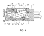
- FIG. 4 show a centrally located cross-section of the blower in the longitudinal direction A and Figure 5 shows a corresponding cross-section of the blower in the transverse direction B.
- the blower housing 20 defines a pair of transversely overlapping cylindrical chambers 41, 42.
- the cylindrical chambers 41, 42 overlap at an inlet cusp 40a which is in-line with the inlet port 23 and at an outlet cusp 40b which is in-line with and interrupted by the outlet port 25.
- the housing 20 defines a first end wall 43 which comprises the inlet port 23.
- the housing 23 defines a second end wall 44.
- the outlet port 25 is formed at an intersection of the first and second chambers 41, 42, adjacent the second end wall 44.
- first rotor 31 disposed within the first cylindrical chamber 41 and disposed within the second cylindrical chamber 42 is a second rotor 32.
- first rotor 31 rotates clockwise while the second rotor rotates counter-clockwise.
- the first rotor 31 includes four lobes 51 and the second rotor 32 includes four lobes 52.
- the first and second axially facing end surfaces 61, 62 of the lobes sealingly cooperate with the first and second end walls 43, 44 of the housing 23, and the top land 53, 54 of each lobe sealingly cooperate with the cylindrical chambers 41, 42 which is well known in the art.
- control volume Air which flows into the cylindrical chambers 41, 42 via the inlet port 23 will flow into a volume, which is defined by two consecutive adjacent lobes 51, 52 of the same rotor 31, 32. As used herein, such a volume is referred to as a "control volume".
- the air contained in a control volume will be carried by its respective lobes as the rotor rotate until the control volume is in communication with the outlet port 25.
- control volume refers, primarily, to the region or volume between two adjacent unmeshed lobes, after the trailing lobe has traversed the inlet cusp 40a, and before the leading lobe has traversed the outlet cusp 40b.
- Figure 6 shows a cross-sectional cut along line A-A in Figure 5 for illustrating the internal leakage that inherently results from a Roots-type blower having a relatively large twist angle.
- the lobes 51, 52 move into and out of mesh.
- one or more blowholes 55 are formed along the outlet cusp 40b.
- a blowhole 55 is an opening through which a preceding control volume is permitted to communicate with an adjacent control volume. Consequently, blowholes 55 provide a possibility for a control volume to equalize in pressure with an adjacent control volume prior to opening to the outlet port 25.
- blowholes 55 occurs in a cyclic manner, i.e., one blowhole 55 is formed by two meshing lobes 51, 52.
- the blowhole 55 moves linearly in a direction towards the outlet port 25 as the lobe mesh moves linearly in the same direction.
- a greater twist angle means a greater helix angle HA of the lobes 51, 52 if the length of the rotors is kept constant.
- a leakage flow 60 is illustrates entering the outlet port 25 and flowing through a first blowhole 55 formed between a first lobe 51a of the first rotor 31 and a first lobe 52a of the second rotor 32, thereby enabling a certain level of pressure equalisation between the pressure downstream the outlet port 25 and a first control volume 70, which is defined by a first and second lobe 51a, 51b of the first rotor 31.
- the leakage flow 60 may subsequently continue from the first control volume 70 to a second control volume 71, which is defined by a first and second lobe 52a, 52b of the second rotor 32, thereby enabling a certain level of pressure equalisation between the pressure downstream the outlet port 25 and the first and second control volumes 70, 71.
- the top land of the first lobe 52a of the second rotor 32 has in this example not yet traversed the boundary of the outlet port 25.
- a third control volume 72 trailing the first control volume 70 of the first rotor 31 is still closed to the leakage flow 60.
- FIG. 7 shows a top view of the first embodiment of the inventive Roots-type blower 1.
- three backflow slots 29 are provided on each side of an axially extending centre line CL in a wall of the housing 20, i.e. in total six backflow slots.
- the centre line CL extends in the longitudinal direction A in the centre between the first and second rotor 31, 32, as viewed from the outlet port side of the housing in Figure 7 .
- Each backflow slot 29 is an opening extending through the housing 20 for effectuating a leakage of fluid between a control volume and a volume outside of the outlet port 25.
- the three backflow slots are provided substantially along a slot axis 22 which makes an angle ⁇ to the longitudinal direction A of the housing 20.
- the slots 29 may have their elongation axis arranged parallel with the associated slot axis 22.
- the centre of each slot 29 may be located on the slot axis.
- the centre of one or more slots 29 may be slightly displaced from the slot axis 22.
- the longitudinal direction A of the housing 20 coincides with a longitudinal axis of the rotors 31, 32.
- the slot axis angle ⁇ is smaller than the helix angle HA of the lobes 51, 52 such that the backflow slots 29 one after the other are brought into contact with the control volume as the top land 53, 54 of the lead lobe 51, 52 of the control volume progressively traverses the slot axis 22.
- each backflow slot 29 has an elongated, substantially rectangular shape.
- the backflow slot 29 has an elongated shape and a length L1 in range of 3 - 25 millimetres, preferably 4 - 20 millimetres, and more preferably 4 - 15 millimetres.
- the backflow slot 29 has preferably a width L2 in range of 1 - 5 millimetres, more preferably 1-3 millimetres.
- the design, e.g. number, size, shape, and position, of the backflow slots 29 is adapted to minimize noise in the specific environment of the Roots-type blower, e.g. in a specific model of a vehicle.
- the frequency of the fundamental tone of the noise generated by the Roots-type blower corresponds to the rotational frequency of the rotors 31, 32.
- overtones i.e. multiples of the fundamental frequency, are also generated.
- the size and shape of the backflow slots 29 effect which overtones that are generated.
- the inclination angle ⁇ of the side surfaces 26, 27 are here indicated.
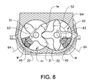
- Figure 8 shows a transverse cross-section of a second embodiment of the inventive Roots-type blower.
- the second end wall 44 of the cylindrical chambers 41, 42 is provided with two bleed recesses 45, one in each cylindrical chamber 41, 42.
- Each bleed recess 45 has typically a depth of a few millimetres, e.g. 2-10 mm, but smaller, larger or variable depths are also possible.
- the angular width w of the bleed recess 45 is larger than the angular width lw of the lobes 51, 52, such that the bleed recess 45 provides a passage between the end surface of the lobe 51, 52 and the second end wall 44. This passage enables fluid to leak between two adjacent control volumes.
- the angular width w of the bleed recess 45 is typically in the range of 1.1 - 2.0 times larger than the angular width lw of the lobes 51, 52.
- the angular width of a lobe 51, 52 or bleed recess 45 is defined as the average width of the lobe 51, 52 or bleed recess 45.
- the width w of the bleed recess 45 is typically smaller than the lobe pair width lpw, i.e. the total width of a pair of lobes, in order not to provide passage between three control volumes. The position, size and and form of the recess is selected according to the specific circumstances.
- a three lobed rotor generally requires a wider bleed recess due the wider lobe width lw, etc.
- the positioning and size of the bleed recess is preferably also selected to avoid that working fluid may bleed from the outlet port to the inlet port.
- the bleed recess may have a width w in the range of 45 - 90 degrees, preferably in the range of 60 - 80 degrees.
- An angle between an angular centre 64 of the bleed recess 45 and a position where the lobe is directed towards the outlet port, in the direction of rotation, may be in the range of 90 - 180 degrees, preferably in the range of 110 - 150 degrees.
- the second embodiment may be successfully implemented on blowers having a large variety of twist angles and a helix angles HA, for example with a twist angle in the range of 0 - 360 degrees.
- helix angle referrers to the angle between a lobe and the axis of the rotor on which the lobe is provided.
- the helix angle is typically calculated at the pitch circle (or pitch diameter) of the rotors.
- twist angle refers to the angle described by a lobe when "travelling" from one end surface to the other end surface of the rotor.
- each bleed recess may be divided into two or more bleed recesses having different angular extensions and/or positions, the location of the inlet port and outlet port may be modified. Accordingly, the drawings and the description thereto are to be regarded as illustrative in nature, and not restrictive.
Landscapes
- Engineering & Computer Science (AREA)
- Mechanical Engineering (AREA)
- General Engineering & Computer Science (AREA)
- Chemical & Material Sciences (AREA)
- Combustion & Propulsion (AREA)
- Applications Or Details Of Rotary Compressors (AREA)
- Wind Motors (AREA)
Abstract
Description
- This invention relates to Roots-type blowers and more particularly to such blowers in which the lobes are twisted. Such Roots-type blowers are commonly used for pumping volumes of air in applications such as boosting or supercharging internal combustion engines of vehicles.
- In vehicle motor applications, Roots-type blower superchargers are used for transferring volumes of air into the combustion chambers of an engine. The transferred volumes of air are greater than the displacement of the engine, thereby increasing the air pressure within the combustion chambers which results in greater engine output power.
- A Roots-type blower is a positive displacement lobe pump which operates by pumping a fluid with a pair of meshing, lobed rotors provided in overlapping rotor chambers. Fluid is trapped in pockets surrounding the lobes and carried from the intake side to an outlet side.
- Modern Roots-type blowers typically have twisted lobes, i.e. the rotor lobes define a helix angle greater than zero relative to the axial direction of the rotor. Another significant parameter in a Roots-type blower is the twist angle of each lobe, i.e. the angular displacement in degrees when travelling along a lobe from one end of the rotor to the other end of the rotor.
- A long-known problem with Roots-type blowers is that they generate high levels of pulsation noise. As disclosed in
US 2006/0263230 A1 , the noise can be reduced by increasing the helix angle of the lobes. A large helix angle results in many "blowholes" being formed in connection with meshing of the lobes as the rotors rotate. The blowholes permit communication between adjacent pockets of fluid, which allows for pressure equalization prior to opening the outlet port. Pressure equalization is known to reduce air turbulence (pulsation) and hence pulsation noise. - However, even with many blowholes a Roots-type blower still may produce a considerable amount of noise. Especially, a Roots-type blower may cause a lot of nuisance in a vehicle if run hard at low engine speeds, as the engine at low speeds does not produce sufficient noise to drown the noise from the Roots-type blower.
- There is thus a need for an improved Roots-type blower at least partly removing the above mentioned disadvantage.
- An object of the present invention is to provide a Roots-type blower having a reduced level of NVH (Noise Vibration Harshness). This object is achieved by the features of
claim - The invention concerns a roots-type blower. The blower comprising a housing defining first and second transversely overlapping cylindrical chambers, and the housing comprising a first end wall and a second end wall. The housing defining at least one inlet port adjacent said first end wall and at least one outlet port adjacent said second end wall. The blower further comprises first and second meshed, lobed rotors disposed, respectively, in said first and second cylindrical chambers. Each rotor includes a plurality of lobes. Each lobe having first and second axially facing end surfaces sealingly cooperating with said first and second end walls, respectively, and a top land sealingly cooperating with said cylindrical chambers. Each lobe further having its first and second axially facing end surfaces defining a twist angle and a helix angle. The blower further comprises a plurality of control volumes for transfer of fluid from the at least one inlet port to the at least one outlet port. Each control volume being defined by a pair of adjacent lobes on one of the rotors, and at least one of the cylindrical chambers, first end wall, and/or second end wall. The blower also has a leakage mechanism for effecting a leakage of fluid between adjacent control volumes. The leakage mechanism including blowholes formed within the cylindrical chambers in connection with meshing of the lobes of the first and second rotors.
- According to one aspect of the invention the Roots-type blower comprises an additional leakage mechanism in form of at least one backflow slot extending through the housing wall of each cylindrical chamber for effecting a leakage of fluid from downstream the at least one outlet port into a control volume prior to traversal of the at least one outlet port boundaries by the top land of the lead lobe of said control volume.
- During operation of the blower the fluid pressure downstream the outlet will generally be significantly larger than the fluid pressure at the inlet port due to the pumping effect of the blower. The fluid pressure within the control volumes will thus also be significantly smaller than the pressure downstream the outlet port. When the control volume opens to the outlet port high pressure fluid will consequently rapidly flow into the control volume and thereby generating turbulence and noise. Roots-type blowers having blowholes as leakage mechanism provides a certain level of pressure equalisation between adjacent control volumes prior to opening to the outlet port. However, it has been found that Roots-type blowers having blowholes as their only leakage mechanism suffer from insufficient pressure equalisation. The insufficient pressure equalisation occurs even when a relatively high twist angle is used, e.g. at least 90 degrees, whereby an increased twist angle results in increased internal leakage for several reasons. For example, with maintained rotor and housing length, maintained rotor speed and merely increased twist angle, an increased number of blowholes are generally present simultaneously in the blower, the existence of each blow hole over time is prolonged, and since the axial air speed within each control volume is reduced there is less likelihood of generating a vacuum at the inlet port, such that increased air pressure within each control volume and reduced turbulence is enabled. The advantage of providing at least one additional leakage mechanism according to the invention is further improved pressure equalisation between adjacent control volumes prior to opening to the outlet port, such that the NVH level generated by the Roots-type blower is further reduced.
- According to a further aspect of the invention the Roots-type blower comprises a leakage mechanism for effecting a leakage of fluid between adjacent control volumes, wherein said leakage mechanism comprises at least one bleed recess provided in the second end wall, and wherein said bleed recess provides a passage between the second axially facing end surface of a lobe and the second end wall such that fluid is enabled to leak between adjacent control volumes. This solution, which is technically different but exhibiting essentially the same technical effect and solving essentially the same problem, also provides pressure equalisation between adjacent control volumes prior to opening to the outlet port, and thereby also and a reduced NVH level. The size, shape and positioning of the bleed recess can be selected according to the specific circumstances to obtain a desired balance of noise dampening and pumping efficiency. Bleed recesses and backflow slots are not mutually exclusive, but may be used in the same blower.
- Further advantages are achieved by implementing one or several of the features of the dependent claims.
- In one aspect of the invention, the additional leakage mechanism comprises at least one individual backflow slot provided on each side of a centre line extending axially in a wall of the housing. A backflow slot is an opening in the housing. The at least one backflow slot allows the control volume to at least partly equalize in pressure with the outflow duct prior to opening to the outlet port. Hence, the aforementioned pressure difference is reduced prior to opening to the outlet port which results in reduced noise.
- Moreover, by providing each cylindrical chamber with at least one individual backflow slot any interference between the working chambers caused by the backflow slot may be eliminated.
- The design, e.g. number, size, shape, and position, of the at least one backflow slot may be adapted to minimize noise in a specific installation of the blower. A specific installation may be for example a specific model of a vehicle. The specific design of each model of a vehicle determines the acoustics within the vehicle. Usually, sound of some frequencies fade away quite immediately, while other frequencies are more long-lived or even amplified. The frequency of the fundamental tone of the noise generated by the Roots-type blower corresponds to the rotational frequency of the rotors. Several overtones, i.e. multiples of the fundamental frequency, are also generated. The size, shape and position of the at least one backflow slot affects which overtones that are generated and to what extent. Thus, the backflow slots may be designed to get rid of certain overtones that would otherwise be long-lived or even amplified in the specific installation.
- The at least one backflow slot may have a substantially rectangular shape. The at least one backflow slot may have an elongated shape and a length in range of 3 - 25 millimetres, preferably 4 - 20 millimetres, and more preferably 4-15 millimetres.
- The additional leakage mechanism may comprise at least two individual backflow slots provided on each side of a centre line, more preferably at least three individual backflow slots provided on each side of a centre line. Provision of many backflow slots enables more fluid to leak and therefore better pressure equalization. Alternatively, one or a few backflow slot of large size could be used instead of a plurality of smaller backflow slots. However, design elements such as reinforcement lines in the housing may hinder the use of large backflow slots, while smaller backflow slots readily may fit between the hindering design elements.
- The individual backflow slots on either side of the centre line are preferably arranged along a slot axis having a slot axis angle to the longitudinal direction of the housing, wherein said slot axis angle is smaller than the helix angle of the lobes, such that the individual backflow slots along each slot axis sequentially enables a fluid flow passage to the control volume as the top land of the lead lobe of the control volume progressively traverses the slot axis. The advantage of such an arrangement is that the pressure within the control volume gradually is equalized with the pressure in the outflow duct as more and more backflow slots open. This gradual pressure equalization reduces turbulence even more, and hence results in even more efficient noise reduction.
- The at least one bleed recess has an angular width greater than an angular width of the lobe.
- In one aspect of the invention, at least two bleed recesses are provided in the second end wall, wherein at least one bleed recess is associated with each individual cylindrical chamber. This arrangement reduces interference between the first and second control volumes.
- Each rotor may typically comprise between three and five lobes. More specifically, each rotor comprises four lobes.
- The twist angle of the lobes may be at least 120°, and more specifically at least 140°. A higher twist angle enables a higher helix angle for a rotor of a given length. And an increased helix angle gives rise to a larger number of blowholes being created within the cylindrical chambers. And furthermore, an increased helix angle results in a lower linear velocity of the blowholes along the rotor. In other words, an increased helix angle leads to more blowholes, which blowholes are also present for a longer period of time. Consequently, there are more blowholes for fluid to leak through, and the leakage can take place during a longer period of time. This results in increased leakage and hence in increased pressure equalization through the blowholes and therefore reduced noise.
- Said twist angle may also be less than 360°, more specifically less than 300°, and even more specifically less than 240°.
- In the detailed description of the invention given below reference is made to the following figures, in which:
- Figure 1
- shows a schematic overview of an engine aspiration assembly comprising a Roots-type blower,
- Figure 2
- shows an external, perspective view of the inventive Roots-type blower,
- Figure 3
- shows a perspective overview of the rotors of the inventive Roots-type blower of
Figure 2 , - Figure 4
- shows a longitudinal cross-section of the Roots-type blower shown in perspective in
Figure 2 , - Figure 5
- shows a transverse cross-section of the Roots-type blower in
figure 2 , - Figure 6
- shows a cross-section along line A-A in
Figure 5 , - Figure 7
- shows a top view of the outlet flange of the inventive Roots-type blower of
Figure 2 , - Figure 8
- shows a transverse cross-section of a second embodiment of the inventive Roots-type blower.
- Various aspects of the invention will hereinafter be described in conjunction with the appended drawings to illustrate and not to limit the invention, wherein like designations denote like elements, and variations of the inventive aspects are not restricted to the specifically shown embodiments, but are applicable on other variations of the invention.
-
Figure 1 shows a schematic overview of anengine aspiration assembly 100 comprising a Roots-type blower 1. Typically, such an engine assembly is found in a motor vehicle, such as for example an automobile, truck, bus or the like. In this example, the Roots-type blower 1 is used in combination with aturbocharger 8 for transferring air into the combustion chambers of theinternal combustion engine 10. The transferred volumes of air are greater than the displacement of theengine 10, thereby increasing the air pressure within the combustion chambers which results in greater engine output power. Air is let into theengine aspiration assembly 100 via anair intake 2 and passes via anair filter 3 for removal of particles harmful to theassembly 100. Abypass valve 4 controls if the incoming air fed via the Roots-type blower 1 or directly to theturbocharger 8. For example, the pumping of the Roots-type blower 1 may be needed at low engine speeds, while being superfluous at higher engine speeds. If thebypass valve 4 is open towards the Roots-type blower 1, air is fed into the Roots-type blower 1 via aninflow duct 5. The pumping mechanism of the Roots-type blower is mechanically driven by adrive belt 7 connected to the engine crankshaft. After being pumped, the air leaves the Roots-type blower 1 via anoutflow duct 6 and is passed on to theturbocharger 8 in which the air may be further pumped. After having passed theturbocharger 8, the air is cooled by anintercooler 9 before entering the combustion chambers of theengine 10. After combustion, exhaust gases are ejected from theengine 10. The exhaust gases drive theturbocharger 8 before leaving theengine aspiration assembly 100 via anexhaust outlet 11. -
Figure 2 shows an external, perspective view of a first embodiment of the inventive Roots-type blower 1 having a longitudinal direction A and a transverse direction B. The Roots-type blower 1 includes ahousing 20. Air enters theblower 1 via theinlet port 23 which is defined by an opening adjacent one end of thehousing 20. Aninlet flange 46 surrounds theinlet port 23 and provides means for connection toinflow duct 5. Anoutlet port 25 is provided on the upper side ofhousing 20. In this example, thesingle outlet port 25 is defined partly by anend surface 28 which extends in the transverse direction B and a pair of inclined side surfaces 26, 27, such that theoutlet port 25 has a substantially triangular shape. The inclined side surfaces 26, 27 are inclined with respect to the longitudinal direction A. The inclination angle is preferably selected to correspond to the helix angle of tworotors housing 20. Anoutlet flange 47 surrounds theoutlet port 25 and provides means for connection to theoutflow duct 6. Theoutlet flange 47 has a rectangular form and encloses an area significantly larger than the flow area of theoutlet port 25. Theexterior surface 48 of thehousing 20 occupies the area enclosed within theoutlet flange 47 that is not part of theoutlet port 25. The housing is reinforced by means of a plurality of transversally extendingreinforcement ribs 49 that are spaced apart in the longitudinal direction A. - A
first rotor 31 and asecond rotor 32 are partly glimpsed through theoutlet port 25. As thelobed rotors inlet port 23 to theoutlet port 25 as the rotors rotate. To provide improved pressure equalisation between consecutive control volumes prior to opening to theoutlet port 25, the housing is provided withbackflow slots 29 which allow the control volume to at least partly equalize in pressure with theoutflow duct 8 prior to opening to theoutlet port 25. The mechanical input to drive therotors belt 7. -
Figure 3 shows a cross-section of theblower housing 20 offigure 2 , as well as thecomplete rotors rotors second rotor shaft rotor shaft housing 20. The twist angle of the rotors is in the shown example 160 degrees. The twist angle refers to the difference in angular orientation of any lobe at a first axially facingend surface 61 and a second axially facingend surface 62. In this example, eachrotor lobes first rotor 31 is connected to thepulley 21 via ashaft 50. - The internal design of the blower will now be described more in detail, wherein
Figure 4 show a centrally located cross-section of the blower in the longitudinal direction A andFigure 5 shows a corresponding cross-section of the blower in the transverse direction B. Theblower housing 20 defines a pair of transversely overlappingcylindrical chambers cylindrical chambers inlet cusp 40a which is in-line with theinlet port 23 and at anoutlet cusp 40b which is in-line with and interrupted by theoutlet port 25. At a first end of thecylindrical chambers housing 20 defines afirst end wall 43 which comprises theinlet port 23. At the opposite end of thechambers housing 23 defines asecond end wall 44. Theoutlet port 25 is formed at an intersection of the first andsecond chambers second end wall 44. - Referring now primarily to
Figure 5 , it may be seen that disposed within the firstcylindrical chamber 41 is afirst rotor 31 and disposed within the secondcylindrical chamber 42 is asecond rotor 32. When viewing the rotors from the inlet as inFigure 5 , thefirst rotor 31 rotates clockwise while the second rotor rotates counter-clockwise. Thefirst rotor 31 includes fourlobes 51 and thesecond rotor 32 includes fourlobes 52. The first and second axially facing end surfaces 61, 62 of the lobes sealingly cooperate with the first andsecond end walls housing 23, and thetop land cylindrical chambers cylindrical chambers inlet port 23 will flow into a volume, which is defined by two consecutiveadjacent lobes same rotor outlet port 25. In other words, the term "control volume" refers, primarily, to the region or volume between two adjacent unmeshed lobes, after the trailing lobe has traversed theinlet cusp 40a, and before the leading lobe has traversed theoutlet cusp 40b. A more detailed description of the movements of the lobes and the corresponding control volumes is provided in for exampleUS 2006/0263230 A1 . -
Figure 6 shows a cross-sectional cut along line A-A inFigure 5 for illustrating the internal leakage that inherently results from a Roots-type blower having a relatively large twist angle. As therotors lobes lobes outlet cusp 40b. A blowhole 55 is an opening through which a preceding control volume is permitted to communicate with an adjacent control volume. Consequently, blowholes 55 provide a possibility for a control volume to equalize in pressure with an adjacent control volume prior to opening to theoutlet port 25. As understood by those skilled in the art, the formation of blowholes 55 occurs in a cyclic manner, i.e., one blowhole 55 is formed by two meshinglobes outlet port 25 as the lobe mesh moves linearly in the same direction. There can be several blowholes 55 present in the Roots-type blower 1 at any one time. The greater the twist angle of thelobes lobes outlet port 25. - In
Figure 6 , aleakage flow 60 is illustrates entering theoutlet port 25 and flowing through a first blowhole 55 formed between afirst lobe 51a of thefirst rotor 31 and a first lobe 52a of thesecond rotor 32, thereby enabling a certain level of pressure equalisation between the pressure downstream theoutlet port 25 and afirst control volume 70, which is defined by a first andsecond lobe 51a, 51b of thefirst rotor 31. Theleakage flow 60 may subsequently continue from thefirst control volume 70 to asecond control volume 71, which is defined by a first and second lobe 52a, 52b of thesecond rotor 32, thereby enabling a certain level of pressure equalisation between the pressure downstream theoutlet port 25 and the first andsecond control volumes second rotor 32 has in this example not yet traversed the boundary of theoutlet port 25. Athird control volume 72 trailing thefirst control volume 70 of thefirst rotor 31 is still closed to theleakage flow 60. -
Figure 7 shows a top view of the first embodiment of the inventive Roots-type blower 1. In this example, threebackflow slots 29 are provided on each side of an axially extending centre line CL in a wall of thehousing 20, i.e. in total six backflow slots. The centre line CL extends in the longitudinal direction A in the centre between the first andsecond rotor Figure 7 . Eachbackflow slot 29 is an opening extending through thehousing 20 for effectuating a leakage of fluid between a control volume and a volume outside of theoutlet port 25. At each side of theoutlet port 25, the three backflow slots are provided substantially along aslot axis 22 which makes an angle α to the longitudinal direction A of thehousing 20. Theslots 29 may have their elongation axis arranged parallel with the associatedslot axis 22. The centre of eachslot 29 may be located on the slot axis. Alternatively, the centre of one ormore slots 29 may be slightly displaced from theslot axis 22. The longitudinal direction A of thehousing 20 coincides with a longitudinal axis of therotors lobes backflow slots 29 one after the other are brought into contact with the control volume as thetop land lead lobe slot axis 22. Consequently, the twobackflow slot 29 located closest to the inlet port will first provide a backflow passage, thereafter the fourbackflow slots 29 located closest to the inlet port will provide a backflow passage, and thereafter all six backflow will provide a backflow passages. In this example, there are sixbackflow slots 29 located in a V-shaped formation around theoutlet port 25. Eachbackflow slot 29 has an elongated, substantially rectangular shape. Thebackflow slot 29 has an elongated shape and a length L1 in range of 3 - 25 millimetres, preferably 4 - 20 millimetres, and more preferably 4 - 15 millimetres. Furthermore, thebackflow slot 29 has preferably a width L2 in range of 1 - 5 millimetres, more preferably 1-3 millimetres. However, other numbers, shapes and positions ofbackflow slots 29 are also possible. Preferably, the design, e.g. number, size, shape, and position, of thebackflow slots 29 is adapted to minimize noise in the specific environment of the Roots-type blower, e.g. in a specific model of a vehicle. The frequency of the fundamental tone of the noise generated by the Roots-type blower corresponds to the rotational frequency of therotors backflow slots 29 effect which overtones that are generated. The inclination angle β of the side surfaces 26, 27 are here indicated. -
Figure 8 shows a transverse cross-section of a second embodiment of the inventive Roots-type blower. In this embodiment, thesecond end wall 44 of thecylindrical chambers cylindrical chamber bleed recess 45 has typically a depth of a few millimetres, e.g. 2-10 mm, but smaller, larger or variable depths are also possible. The angular width w of thebleed recess 45 is larger than the angular width lw of thelobes bleed recess 45 provides a passage between the end surface of thelobe second end wall 44. This passage enables fluid to leak between two adjacent control volumes. The angular width w of thebleed recess 45 is typically in the range of 1.1 - 2.0 times larger than the angular width lw of thelobes lobe recess 45 is defined as the average width of thelobe recess 45. The width w of thebleed recess 45 is typically smaller than the lobe pair width lpw, i.e. the total width of a pair of lobes, in order not to provide passage between three control volumes. The position, size and and form of the recess is selected according to the specific circumstances. A three lobed rotor generally requires a wider bleed recess due the wider lobe width lw, etc. The positioning and size of the bleed recess is preferably also selected to avoid that working fluid may bleed from the outlet port to the inlet port. In the specific example shown infig. 8 , the bleed recess may have a width w in the range of 45 - 90 degrees, preferably in the range of 60 - 80 degrees. An angle between anangular centre 64 of thebleed recess 45 and a position where the lobe is directed towards the outlet port, in the direction of rotation, may be in the range of 90 - 180 degrees, preferably in the range of 110 - 150 degrees. The second embodiment may be successfully implemented on blowers having a large variety of twist angles and a helix angles HA, for example with a twist angle in the range of 0 - 360 degrees. - The term helix angle herein referrers to the angle between a lobe and the axis of the rotor on which the lobe is provided. The helix angle is typically calculated at the pitch circle (or pitch diameter) of the rotors. The term twist angle herein refers to the angle described by a lobe when "travelling" from one end surface to the other end surface of the rotor.
- Reference signs mentioned in the claims should not be seen as limiting the extent of the matter protected by the claims, and their sole function is to make claims easier to understand. As will be realised, the invention is capable of modification in various obvious respects, all without departing from the scope of the appended claims. For example, each bleed recess may be divided into two or more bleed recesses having different angular extensions and/or positions, the location of the inlet port and outlet port may be modified. Accordingly, the drawings and the description thereto are to be regarded as illustrative in nature, and not restrictive.
Claims (15)
- A Roots-type blower (1) comprising:- a housing (20) defining first and second transversely overlapping cylindrical chambers (41, 42), said housing (20) comprising a first end wall (43) and a second end wall (44), said housing (20) defining at least one inlet port (23) adjacent said first end wall (43) and at least one outlet port (25) adjacent said second end wall (44);- first and second meshed, lobed rotors (31, 32) disposed, respectively, in said first and second cylindrical chambers (41, 42); each rotor including a plurality N of lobes (51, 52), each lobe having first and second axially facing end surfaces sealingly cooperating with said first and second end walls (43, 44), respectively, and a top land (53, 54) sealingly cooperating with said cylindrical chambers (41, 42), each lobe (51, 52) having its first and second axially facing end surfaces (61, 62) defining a twist angle of at least 90°, and each lobe (51, 52) defining a helix angle (HA);- a plurality of control volumes for transfer of fluid from the at least one inlet port (23) to the at least one outlet port (25), each control volume being defined by a pair of adjacent lobes (51, 52) on one of the rotors (31, 32), and at least one of the cylindrical chambers (41, 42), first end wall (43), and/or second end wall (44); and- a leakage mechanism for effecting a leakage of fluid between adjacent control volumes, said leakage mechanism including blowholes (55) formed within the cylindrical chambers (41, 42) in connection with meshing of the lobes (51, 52) of the first and second rotors (31, 32);characterized in that the Roots-type blower (1) comprises an additional leakage mechanism (29) in form of at least one backflow slot (29) extending through the housing (20) wall of each cylindrical chamber (41, 42) for effecting a leakage of fluid from downstream the at least one outlet port (25) into a control volume prior to traversal of the at least one outlet port (25) boundaries by the top land (53, 54) of the lead lobe (51, 52) of said control volume.
- A Roots-type blower (1) according to claim 1, characterized in that the additional leakage mechanism comprises at least one individual backflow slot (29) provided on each side of an axially extending centre line (CL) in a wall of the housing (20).
- A Roots-type blower (1) according to any of the preceding claims, characterized in that the additional leakage mechanism comprises at least two individual backflow slots (29) provided on each side of a centre line (CL), more preferably at least three individual backflow slots (29) provided on each side of a centre line (CL).
- A Roots-type blower (1) according to claim 3, characterized in that the individual backflow slots (29) on either side of the centre line (CL) are arranged along a slot axis (22) having a slot axis angle (α) to the longitudinal direction (A) of the housing (20), wherein said slot axis angle (α) is smaller than the helix angle (HA) of the lobes (51, 52), such that the individual backflow slots (29) along each slot axis (22) sequentially enables a fluid flow passage to the control volume as the top land (53, 54) of the lead lobe (51, 52) of the control volume progressively traverses the slot axis (22).
- A Roots-type blower (1) according to any of preceding claims 1- 4, characterized in that said at least one backflow slot (29) has a substantially rectangular shape.
- A Roots-type blower (1) according to any of preceding claim 5, characterized in that said at least one backflow slot (29) has an elongated shape and a length (L1) in range of 3 - 25 millimetres, preferably 4 - 20 millimetres, and more preferably 4 - 15 millimetres.
- A Roots-type blower (1) according to any of preceding claims 2 - 6, characterized in that at least one backflow slot (29) is provided on either side of the outlet port (25).
- A Roots-type blower (1) according to any of preceding claims 3 - 7, characterized in that the housing (20) comprises at least one reinforcing rib (21) projecting outwardly from an exterior surface (35) of the housing (20) and extending in a direction perpendicular to the longitudinal direction (A), and the at least two individual backflow slots (29) provided on each side of a centre line (CL) are provided on each side of the reinforcing rib (21).
- A Roots-type blower (1) according to any of the preceding claims, characterized in that the blowhole (55) between adjacent control volumes is formed in regions along the longitudinal direction (A) of the blower (1) where the lobe (51, 52) of any rotor (31, 32) is located between an angular position where the top land (53, 54) has passed the outlet cusp (40b) and an angular position where the lobe sealingly closes the control volume upon meshing with lobes (52, 51) of the other rotor (32, 31).
- A Roots-type blower (1) comprising:- a housing (20) defining first and second transversely overlapping cylindrical chambers (41, 42), said housing (20) comprising a first end wall (43) and a second end wall (44), said housing (20) defining at least one inlet port (23) adjacent said first end wall (43) and at least one outlet port (25) adjacent said second end wall (44);- first and second meshed, lobed rotors (31, 32) disposed, respectively, in said first and second cylindrical chambers (41, 42); each rotor including a plurality N of lobes (51, 52), each lobe having first and second axially facing end surfaces sealingly cooperating with said first and second end walls (43, 44), respectively, and a top land (53, 54) sealingly cooperating with said cylindrical chambers (41, 42), each lobe (51, 52) having its first and second axially facing end surfaces defining a twist angle and each lobe (51, 52) defining a helix angle (HA); and- a plurality of control volumes for transfer of fluid from the at least one inlet port (23) to the at least one outlet port (25), each control volume being defined by a pair of adjacent lobes (51, 52) on one of the rotors (31, 32), and at least one of the cylindrical chambers (41, 42), first end wall (43), and/or second end wall (44);characterized in that the Roots-type blower (1) comprises a leakage mechanism for effecting a leakage of fluid between adjacent control volumes, said leakage mechanism comprises at least one bleed recess (45) provided in the second end wall (44), wherein said bleed recess (45) provides a passage between the second axially facing end surface (62) of a lobe (51, 52) and the second end wall (44) such that fluid is enabled to leak between adjacent control volumes.
- A Roots-type blower (1) according to claim 10, characterized in that at least two bleed recesses (45) are provided in the second end wall (44), wherein at least one bleed recess (45) is associated with each individual cylindrical chamber (41, 42).
- A Roots-type blower (1) according to any of the preceding claims 10 - 11, characterized in that each of the at least two bleed recesses (45) has an angular width (w) greater than an angular width (lw) of a lobe.
- A Roots-type blower (1) according to any of the preceding claims 10 - 12, characterized in that said at least one bleed recess (45) associated with each individual cylindrical chamber (41, 42) is located to enable a leakage of fluid between adjacent control volumes only after each of said adjacent control volumes is lacking fluid communication with the inlet port (23).
- A Roots-type blower (1) according to any of the preceding claims, characterized in that said twist angle of the lobes (51, 52) is at least 120°, specifically at least 140°.
- A Roots-type blower (1) according to any of the preceding claims, characterized in that said twist angle of the lobes (51, 52) is less than 360°, specifically less than 300°, and more specifically less than 240°.
Priority Applications (3)
| Application Number | Priority Date | Filing Date | Title |
|---|---|---|---|
| EP13192052.2A EP2871367B1 (en) | 2013-11-08 | 2013-11-08 | Roots-style blower with leakage mechanisms |
| US14/535,831 US9617998B2 (en) | 2013-11-08 | 2014-11-07 | Roots-style blower with leakage mechanisms |
| CN201410858300.3A CN104632618B (en) | 2013-11-08 | 2014-11-10 | Roots-type wind turbine with leakage mechanism |
Applications Claiming Priority (1)
| Application Number | Priority Date | Filing Date | Title |
|---|---|---|---|
| EP13192052.2A EP2871367B1 (en) | 2013-11-08 | 2013-11-08 | Roots-style blower with leakage mechanisms |
Publications (2)
| Publication Number | Publication Date |
|---|---|
| EP2871367A1 true EP2871367A1 (en) | 2015-05-13 |
| EP2871367B1 EP2871367B1 (en) | 2016-04-27 |
Family
ID=49551536
Family Applications (1)
| Application Number | Title | Priority Date | Filing Date |
|---|---|---|---|
| EP13192052.2A Active EP2871367B1 (en) | 2013-11-08 | 2013-11-08 | Roots-style blower with leakage mechanisms |
Country Status (3)
| Country | Link |
|---|---|
| US (1) | US9617998B2 (en) |
| EP (1) | EP2871367B1 (en) |
| CN (1) | CN104632618B (en) |
Cited By (1)
| Publication number | Priority date | Publication date | Assignee | Title |
|---|---|---|---|---|
| CN115773243A (en) * | 2022-12-08 | 2023-03-10 | 西安交通大学 | A Roots Hydrogen Pump Applied to Fuel Cell Vehicle System |
Families Citing this family (13)
| Publication number | Priority date | Publication date | Assignee | Title |
|---|---|---|---|---|
| US10436197B2 (en) | 2005-05-23 | 2019-10-08 | Eaton Intelligent Power Limited | Optimized helix angle rotors for roots-style supercharger |
| US11286932B2 (en) | 2005-05-23 | 2022-03-29 | Eaton Intelligent Power Limited | Optimized helix angle rotors for roots-style supercharger |
| US9683521B2 (en) * | 2013-10-31 | 2017-06-20 | Eaton Corporation | Thermal abatement systems |
| USD788174S1 (en) * | 2015-10-26 | 2017-05-30 | Eaton Corporation | Supercharger housing |
| USD819084S1 (en) | 2015-11-02 | 2018-05-29 | Eaton Corporation | Supercharger housing having integrated cooling fins |
| USD786934S1 (en) * | 2015-11-02 | 2017-05-16 | Eaton Corporation | Supercharger housing having integrated cooling fins |
| WO2018093999A1 (en) * | 2016-11-17 | 2018-05-24 | Eaton Corporation | Optimized helix angle rotors for roots-style supercharger |
| USD894239S1 (en) | 2017-09-15 | 2020-08-25 | Eaton Corporation | Supercharger |
| CN109915365B (en) * | 2019-04-04 | 2023-11-17 | 烟台东德氢能技术有限公司 | Roots type air compressor |
| CN109973391A (en) * | 2019-05-05 | 2019-07-05 | 烟台菱辰能源有限公司 | A kind of denoising device of Roots's air compressor machine for fuel cell |
| CN110307154A (en) * | 2019-07-15 | 2019-10-08 | 烟台菱辰能源有限公司 | A kind of roots-type hydrogen gas circulating pump |
| CN116663266A (en) * | 2023-05-16 | 2023-08-29 | 山东省章丘鼓风机股份有限公司 | A Design Method of Low Noise Roots Blower |
| CN118188532B (en) * | 2024-05-15 | 2024-08-13 | 江苏兆胜空调有限公司 | Marine high-pressure explosion-proof fan |
Citations (5)
| Publication number | Priority date | Publication date | Assignee | Title |
|---|---|---|---|---|
| EP0225070A1 (en) * | 1985-11-18 | 1987-06-10 | Eaton Corporation | Port arrangement for rotary positive displacement blower |
| JP2004270545A (en) * | 2003-03-07 | 2004-09-30 | Shin Meiwa Ind Co Ltd | Roots type fluid machine |
| US20040194766A1 (en) * | 2003-04-04 | 2004-10-07 | Prior Gregory P. | Supercharger with multiple backflow ports for noise control |
| US20060263230A1 (en) * | 2005-05-23 | 2006-11-23 | Matthew G. Swartzlander | Optimized helix angle rotors for Roots-style supercharger |
| US20120014825A1 (en) * | 2010-07-14 | 2012-01-19 | Kabushiki Kaisha Toyota Jidoshokki | Roots type fluid machine |
Family Cites Families (4)
| Publication number | Priority date | Publication date | Assignee | Title |
|---|---|---|---|---|
| JP2884067B2 (en) * | 1996-06-28 | 1999-04-19 | 株式会社アンレット | Roots blower |
| JP2001295780A (en) * | 2000-04-17 | 2001-10-26 | Ishikawajima Harima Heavy Ind Co Ltd | Roots type supercharger and its noise reduction method |
| EP1286053A1 (en) * | 2001-08-21 | 2003-02-26 | Ford Global Technologies, Inc., A subsidiary of Ford Motor Company | Rotary pump with backflow |
| CN201836050U (en) * | 2010-11-01 | 2011-05-18 | 山东章晃机械工业有限公司 | Roots blower with pressure-balancing counter-current holes |
-
2013
- 2013-11-08 EP EP13192052.2A patent/EP2871367B1/en active Active
-
2014
- 2014-11-07 US US14/535,831 patent/US9617998B2/en active Active
- 2014-11-10 CN CN201410858300.3A patent/CN104632618B/en active Active
Patent Citations (5)
| Publication number | Priority date | Publication date | Assignee | Title |
|---|---|---|---|---|
| EP0225070A1 (en) * | 1985-11-18 | 1987-06-10 | Eaton Corporation | Port arrangement for rotary positive displacement blower |
| JP2004270545A (en) * | 2003-03-07 | 2004-09-30 | Shin Meiwa Ind Co Ltd | Roots type fluid machine |
| US20040194766A1 (en) * | 2003-04-04 | 2004-10-07 | Prior Gregory P. | Supercharger with multiple backflow ports for noise control |
| US20060263230A1 (en) * | 2005-05-23 | 2006-11-23 | Matthew G. Swartzlander | Optimized helix angle rotors for Roots-style supercharger |
| US20120014825A1 (en) * | 2010-07-14 | 2012-01-19 | Kabushiki Kaisha Toyota Jidoshokki | Roots type fluid machine |
Cited By (2)
| Publication number | Priority date | Publication date | Assignee | Title |
|---|---|---|---|---|
| CN115773243A (en) * | 2022-12-08 | 2023-03-10 | 西安交通大学 | A Roots Hydrogen Pump Applied to Fuel Cell Vehicle System |
| CN115773243B (en) * | 2022-12-08 | 2023-10-24 | 西安交通大学 | Roots hydrogen pump applied to fuel cell automobile system |
Also Published As
| Publication number | Publication date |
|---|---|
| US20150132171A1 (en) | 2015-05-14 |
| US9617998B2 (en) | 2017-04-11 |
| CN104632618B (en) | 2018-05-29 |
| EP2871367B1 (en) | 2016-04-27 |
| CN104632618A (en) | 2015-05-20 |
Similar Documents
| Publication | Publication Date | Title |
|---|---|---|
| EP2871367B1 (en) | Roots-style blower with leakage mechanisms | |
| KR102056112B1 (en) | Compressors, Exhaust Gas Turbochargers and Internal Combustion Engines | |
| JP6413980B2 (en) | Turbocharger exhaust turbine | |
| US7866966B2 (en) | Optimized helix angle rotors for Roots-style supercharger | |
| CN105464789B (en) | Twin-scroll turbocharger device for internal combustion engine and control method thereof | |
| US9822781B2 (en) | Optimized helix angle rotors for roots-style supercharger | |
| US20150063989A1 (en) | Compressor of turbocharger | |
| US10436197B2 (en) | Optimized helix angle rotors for roots-style supercharger | |
| CN102046927A (en) | Variable capacity turbine | |
| WO2016035329A1 (en) | Exhaust turbine for turbocharger | |
| CN103174470A (en) | Throttling assembly of a throttling gear for controlling and/or adjusting brake operation of motor | |
| CN103541899B (en) | Screw compressor | |
| CN102046980B (en) | Screw compressors with asymmetric ports | |
| JP2016053352A (en) | Turbocharger exhaust turbine | |
| CN102337992B (en) | Variable intake-type air cleaner | |
| US20140165561A1 (en) | Supercharger Turbocharger Bypass Back Draft Inlet Damper for Series Operation | |
| US11286932B2 (en) | Optimized helix angle rotors for roots-style supercharger | |
| JP2000064919A (en) | Intake device | |
| KR100579747B1 (en) | Continuous Variable Intake System for Automotive | |
| KR20030039476A (en) | Resonator apparatus | |
| JP4410772B2 (en) | Intake device for multi-cylinder internal combustion engine | |
| KR100836042B1 (en) | Variable Intake System for Automotive | |
| KR100372232B1 (en) | Variable resonator | |
| JPH0821250A (en) | Supercharger | |
| JP2010151100A (en) | Turbo supercharger for internal combustion engine |
Legal Events
| Date | Code | Title | Description |
|---|---|---|---|
| PUAI | Public reference made under article 153(3) epc to a published international application that has entered the european phase |
Free format text: ORIGINAL CODE: 0009012 |
|
| 17P | Request for examination filed |
Effective date: 20131108 |
|
| AK | Designated contracting states |
Kind code of ref document: A1 Designated state(s): AL AT BE BG CH CY CZ DE DK EE ES FI FR GB GR HR HU IE IS IT LI LT LU LV MC MK MT NL NO PL PT RO RS SE SI SK SM TR |
|
| AX | Request for extension of the european patent |
Extension state: BA ME |
|
| R17P | Request for examination filed (corrected) |
Effective date: 20151113 |
|
| RBV | Designated contracting states (corrected) |
Designated state(s): AL AT BE BG CH CY CZ DE DK EE ES FI FR GB GR HR HU IE IS IT LI LT LU LV MC MK MT NL NO PL PT RO RS SE SI SK SM TR |
|
| RIC1 | Information provided on ipc code assigned before grant |
Ipc: F04C 29/06 20060101ALI20151204BHEP Ipc: F04C 29/12 20060101AFI20151204BHEP Ipc: F04C 15/00 20060101ALI20151204BHEP Ipc: F04C 18/107 20060101ALI20151204BHEP Ipc: F04C 18/12 20060101ALI20151204BHEP |
|
| GRAP | Despatch of communication of intention to grant a patent |
Free format text: ORIGINAL CODE: EPIDOSNIGR1 |
|
| INTG | Intention to grant announced |
Effective date: 20160126 |
|
| GRAS | Grant fee paid |
Free format text: ORIGINAL CODE: EPIDOSNIGR3 |
|
| GRAA | (expected) grant |
Free format text: ORIGINAL CODE: 0009210 |
|
| AK | Designated contracting states |
Kind code of ref document: B1 Designated state(s): AL AT BE BG CH CY CZ DE DK EE ES FI FR GB GR HR HU IE IS IT LI LT LU LV MC MK MT NL NO PL PT RO RS SE SI SK SM TR |
|
| REG | Reference to a national code |
Ref country code: GB Ref legal event code: FG4D |
|
| REG | Reference to a national code |
Ref country code: CH Ref legal event code: EP |
|
| REG | Reference to a national code |
Ref country code: AT Ref legal event code: REF Ref document number: 795131 Country of ref document: AT Kind code of ref document: T Effective date: 20160515 |
|
| REG | Reference to a national code |
Ref country code: IE Ref legal event code: FG4D |
|
| REG | Reference to a national code |
Ref country code: DE Ref legal event code: R096 Ref document number: 602013006937 Country of ref document: DE |
|
| REG | Reference to a national code |
Ref country code: SE Ref legal event code: TRGR |
|
| REG | Reference to a national code |
Ref country code: LT Ref legal event code: MG4D |
|
| REG | Reference to a national code |
Ref country code: NL Ref legal event code: MP Effective date: 20160427 |
|
| REG | Reference to a national code |
Ref country code: AT Ref legal event code: MK05 Ref document number: 795131 Country of ref document: AT Kind code of ref document: T Effective date: 20160427 |
|
| PG25 | Lapsed in a contracting state [announced via postgrant information from national office to epo] |
Ref country code: NL Free format text: LAPSE BECAUSE OF FAILURE TO SUBMIT A TRANSLATION OF THE DESCRIPTION OR TO PAY THE FEE WITHIN THE PRESCRIBED TIME-LIMIT Effective date: 20160427 |
|
| PG25 | Lapsed in a contracting state [announced via postgrant information from national office to epo] |
Ref country code: NO Free format text: LAPSE BECAUSE OF FAILURE TO SUBMIT A TRANSLATION OF THE DESCRIPTION OR TO PAY THE FEE WITHIN THE PRESCRIBED TIME-LIMIT Effective date: 20160727 Ref country code: PL Free format text: LAPSE BECAUSE OF FAILURE TO SUBMIT A TRANSLATION OF THE DESCRIPTION OR TO PAY THE FEE WITHIN THE PRESCRIBED TIME-LIMIT Effective date: 20160427 Ref country code: LT Free format text: LAPSE BECAUSE OF FAILURE TO SUBMIT A TRANSLATION OF THE DESCRIPTION OR TO PAY THE FEE WITHIN THE PRESCRIBED TIME-LIMIT Effective date: 20160427 Ref country code: FI Free format text: LAPSE BECAUSE OF FAILURE TO SUBMIT A TRANSLATION OF THE DESCRIPTION OR TO PAY THE FEE WITHIN THE PRESCRIBED TIME-LIMIT Effective date: 20160427 |
|
| PG25 | Lapsed in a contracting state [announced via postgrant information from national office to epo] |
Ref country code: RS Free format text: LAPSE BECAUSE OF FAILURE TO SUBMIT A TRANSLATION OF THE DESCRIPTION OR TO PAY THE FEE WITHIN THE PRESCRIBED TIME-LIMIT Effective date: 20160427 Ref country code: AT Free format text: LAPSE BECAUSE OF FAILURE TO SUBMIT A TRANSLATION OF THE DESCRIPTION OR TO PAY THE FEE WITHIN THE PRESCRIBED TIME-LIMIT Effective date: 20160427 Ref country code: ES Free format text: LAPSE BECAUSE OF FAILURE TO SUBMIT A TRANSLATION OF THE DESCRIPTION OR TO PAY THE FEE WITHIN THE PRESCRIBED TIME-LIMIT Effective date: 20160427 Ref country code: PT Free format text: LAPSE BECAUSE OF FAILURE TO SUBMIT A TRANSLATION OF THE DESCRIPTION OR TO PAY THE FEE WITHIN THE PRESCRIBED TIME-LIMIT Effective date: 20160829 Ref country code: HR Free format text: LAPSE BECAUSE OF FAILURE TO SUBMIT A TRANSLATION OF THE DESCRIPTION OR TO PAY THE FEE WITHIN THE PRESCRIBED TIME-LIMIT Effective date: 20160427 Ref country code: GR Free format text: LAPSE BECAUSE OF FAILURE TO SUBMIT A TRANSLATION OF THE DESCRIPTION OR TO PAY THE FEE WITHIN THE PRESCRIBED TIME-LIMIT Effective date: 20160728 Ref country code: LV Free format text: LAPSE BECAUSE OF FAILURE TO SUBMIT A TRANSLATION OF THE DESCRIPTION OR TO PAY THE FEE WITHIN THE PRESCRIBED TIME-LIMIT Effective date: 20160427 |
|
| PG25 | Lapsed in a contracting state [announced via postgrant information from national office to epo] |
Ref country code: IT Free format text: LAPSE BECAUSE OF FAILURE TO SUBMIT A TRANSLATION OF THE DESCRIPTION OR TO PAY THE FEE WITHIN THE PRESCRIBED TIME-LIMIT Effective date: 20160427 Ref country code: BE Free format text: LAPSE BECAUSE OF FAILURE TO SUBMIT A TRANSLATION OF THE DESCRIPTION OR TO PAY THE FEE WITHIN THE PRESCRIBED TIME-LIMIT Effective date: 20160427 |
|
| REG | Reference to a national code |
Ref country code: DE Ref legal event code: R097 Ref document number: 602013006937 Country of ref document: DE |
|
| PG25 | Lapsed in a contracting state [announced via postgrant information from national office to epo] |
Ref country code: EE Free format text: LAPSE BECAUSE OF FAILURE TO SUBMIT A TRANSLATION OF THE DESCRIPTION OR TO PAY THE FEE WITHIN THE PRESCRIBED TIME-LIMIT Effective date: 20160427 Ref country code: CZ Free format text: LAPSE BECAUSE OF FAILURE TO SUBMIT A TRANSLATION OF THE DESCRIPTION OR TO PAY THE FEE WITHIN THE PRESCRIBED TIME-LIMIT Effective date: 20160427 Ref country code: RO Free format text: LAPSE BECAUSE OF FAILURE TO SUBMIT A TRANSLATION OF THE DESCRIPTION OR TO PAY THE FEE WITHIN THE PRESCRIBED TIME-LIMIT Effective date: 20160427 Ref country code: DK Free format text: LAPSE BECAUSE OF FAILURE TO SUBMIT A TRANSLATION OF THE DESCRIPTION OR TO PAY THE FEE WITHIN THE PRESCRIBED TIME-LIMIT Effective date: 20160427 Ref country code: SK Free format text: LAPSE BECAUSE OF FAILURE TO SUBMIT A TRANSLATION OF THE DESCRIPTION OR TO PAY THE FEE WITHIN THE PRESCRIBED TIME-LIMIT Effective date: 20160427 |
|
| PG25 | Lapsed in a contracting state [announced via postgrant information from national office to epo] |
Ref country code: SM Free format text: LAPSE BECAUSE OF FAILURE TO SUBMIT A TRANSLATION OF THE DESCRIPTION OR TO PAY THE FEE WITHIN THE PRESCRIBED TIME-LIMIT Effective date: 20160427 |
|
| PLBE | No opposition filed within time limit |
Free format text: ORIGINAL CODE: 0009261 |
|
| STAA | Information on the status of an ep patent application or granted ep patent |
Free format text: STATUS: NO OPPOSITION FILED WITHIN TIME LIMIT |
|
| 26N | No opposition filed |
Effective date: 20170130 |
|
| PG25 | Lapsed in a contracting state [announced via postgrant information from national office to epo] |
Ref country code: SI Free format text: LAPSE BECAUSE OF FAILURE TO SUBMIT A TRANSLATION OF THE DESCRIPTION OR TO PAY THE FEE WITHIN THE PRESCRIBED TIME-LIMIT Effective date: 20160427 |
|
| REG | Reference to a national code |
Ref country code: CH Ref legal event code: PL |
|
| PG25 | Lapsed in a contracting state [announced via postgrant information from national office to epo] |
Ref country code: CH Free format text: LAPSE BECAUSE OF NON-PAYMENT OF DUE FEES Effective date: 20161130 Ref country code: LI Free format text: LAPSE BECAUSE OF NON-PAYMENT OF DUE FEES Effective date: 20161130 |
|
| REG | Reference to a national code |
Ref country code: IE Ref legal event code: MM4A |
|
| REG | Reference to a national code |
Ref country code: FR Ref legal event code: ST Effective date: 20170731 |
|
| PG25 | Lapsed in a contracting state [announced via postgrant information from national office to epo] |
Ref country code: LU Free format text: LAPSE BECAUSE OF NON-PAYMENT OF DUE FEES Effective date: 20161130 |
|
| PG25 | Lapsed in a contracting state [announced via postgrant information from national office to epo] |
Ref country code: FR Free format text: LAPSE BECAUSE OF NON-PAYMENT OF DUE FEES Effective date: 20161130 |
|
| PG25 | Lapsed in a contracting state [announced via postgrant information from national office to epo] |
Ref country code: IE Free format text: LAPSE BECAUSE OF NON-PAYMENT OF DUE FEES Effective date: 20161108 |
|
| PG25 | Lapsed in a contracting state [announced via postgrant information from national office to epo] |
Ref country code: HU Free format text: LAPSE BECAUSE OF FAILURE TO SUBMIT A TRANSLATION OF THE DESCRIPTION OR TO PAY THE FEE WITHIN THE PRESCRIBED TIME-LIMIT; INVALID AB INITIO Effective date: 20131108 |
|
| PG25 | Lapsed in a contracting state [announced via postgrant information from national office to epo] |
Ref country code: MC Free format text: LAPSE BECAUSE OF FAILURE TO SUBMIT A TRANSLATION OF THE DESCRIPTION OR TO PAY THE FEE WITHIN THE PRESCRIBED TIME-LIMIT Effective date: 20160427 Ref country code: MK Free format text: LAPSE BECAUSE OF FAILURE TO SUBMIT A TRANSLATION OF THE DESCRIPTION OR TO PAY THE FEE WITHIN THE PRESCRIBED TIME-LIMIT Effective date: 20160427 Ref country code: IS Free format text: LAPSE BECAUSE OF FAILURE TO SUBMIT A TRANSLATION OF THE DESCRIPTION OR TO PAY THE FEE WITHIN THE PRESCRIBED TIME-LIMIT Effective date: 20160427 Ref country code: CY Free format text: LAPSE BECAUSE OF FAILURE TO SUBMIT A TRANSLATION OF THE DESCRIPTION OR TO PAY THE FEE WITHIN THE PRESCRIBED TIME-LIMIT Effective date: 20160427 |
|
| PG25 | Lapsed in a contracting state [announced via postgrant information from national office to epo] |
Ref country code: BG Free format text: LAPSE BECAUSE OF FAILURE TO SUBMIT A TRANSLATION OF THE DESCRIPTION OR TO PAY THE FEE WITHIN THE PRESCRIBED TIME-LIMIT Effective date: 20160427 |
|
| PG25 | Lapsed in a contracting state [announced via postgrant information from national office to epo] |
Ref country code: MT Free format text: LAPSE BECAUSE OF NON-PAYMENT OF DUE FEES Effective date: 20161108 |
|
| PG25 | Lapsed in a contracting state [announced via postgrant information from national office to epo] |
Ref country code: AL Free format text: LAPSE BECAUSE OF FAILURE TO SUBMIT A TRANSLATION OF THE DESCRIPTION OR TO PAY THE FEE WITHIN THE PRESCRIBED TIME-LIMIT Effective date: 20160427 Ref country code: TR Free format text: LAPSE BECAUSE OF FAILURE TO SUBMIT A TRANSLATION OF THE DESCRIPTION OR TO PAY THE FEE WITHIN THE PRESCRIBED TIME-LIMIT Effective date: 20160427 |
|
| PGFP | Annual fee paid to national office [announced via postgrant information from national office to epo] |
Ref country code: SE Payment date: 20181116 Year of fee payment: 6 |
|
| PGFP | Annual fee paid to national office [announced via postgrant information from national office to epo] |
Ref country code: GB Payment date: 20181114 Year of fee payment: 6 |
|
| REG | Reference to a national code |
Ref country code: SE Ref legal event code: EUG |
|
| PG25 | Lapsed in a contracting state [announced via postgrant information from national office to epo] |
Ref country code: SE Free format text: LAPSE BECAUSE OF NON-PAYMENT OF DUE FEES Effective date: 20191109 |
|
| GBPC | Gb: european patent ceased through non-payment of renewal fee |
Effective date: 20191108 |
|
| PG25 | Lapsed in a contracting state [announced via postgrant information from national office to epo] |
Ref country code: GB Free format text: LAPSE BECAUSE OF NON-PAYMENT OF DUE FEES Effective date: 20191108 |
|
| P01 | Opt-out of the competence of the unified patent court (upc) registered |
Effective date: 20231212 |
|
| PGFP | Annual fee paid to national office [announced via postgrant information from national office to epo] |
Ref country code: DE Payment date: 20251022 Year of fee payment: 13 |