EP2871343A1 - Method to control a wastegate valve in a turbocharged internal combustion engine - Google Patents
Method to control a wastegate valve in a turbocharged internal combustion engine Download PDFInfo
- Publication number
- EP2871343A1 EP2871343A1 EP20140192926 EP14192926A EP2871343A1 EP 2871343 A1 EP2871343 A1 EP 2871343A1 EP 20140192926 EP20140192926 EP 20140192926 EP 14192926 A EP14192926 A EP 14192926A EP 2871343 A1 EP2871343 A1 EP 2871343A1
- Authority
- EP
- European Patent Office
- Prior art keywords
- contribution
- obj
- objective
- wastegate valve
- function
- Prior art date
- Legal status (The legal status is an assumption and is not a legal conclusion. Google has not performed a legal analysis and makes no representation as to the accuracy of the status listed.)
- Granted
Links
- 238000002485 combustion reaction Methods 0.000 title claims abstract description 71
- 238000000034 method Methods 0.000 title claims abstract description 31
- 230000006835 compression Effects 0.000 claims description 30
- 238000007906 compression Methods 0.000 claims description 30
- 238000011144 upstream manufacturing Methods 0.000 claims description 27
- 238000013461 design Methods 0.000 claims description 4
- 238000012545 processing Methods 0.000 claims description 2
- 230000006870 function Effects 0.000 description 46
- 230000002000 scavenging effect Effects 0.000 description 43
- 238000004364 calculation method Methods 0.000 description 33
- 239000012528 membrane Substances 0.000 description 13
- 230000003044 adaptive effect Effects 0.000 description 10
- 230000001052 transient effect Effects 0.000 description 9
- 239000007789 gas Substances 0.000 description 8
- 230000009471 action Effects 0.000 description 7
- 230000036316 preload Effects 0.000 description 6
- 230000010355 oscillation Effects 0.000 description 5
- 230000033001 locomotion Effects 0.000 description 4
- 230000001464 adherent effect Effects 0.000 description 3
- 230000006399 behavior Effects 0.000 description 3
- 238000010586 diagram Methods 0.000 description 3
- 238000009499 grossing Methods 0.000 description 3
- 238000005259 measurement Methods 0.000 description 3
- 230000004044 response Effects 0.000 description 3
- 239000003054 catalyst Substances 0.000 description 2
- 238000010276 construction Methods 0.000 description 2
- 239000000110 cooling liquid Substances 0.000 description 2
- 238000012937 correction Methods 0.000 description 2
- 239000006185 dispersion Substances 0.000 description 2
- 238000006073 displacement reaction Methods 0.000 description 2
- 230000003534 oscillatory effect Effects 0.000 description 2
- 230000009467 reduction Effects 0.000 description 2
- 230000002238 attenuated effect Effects 0.000 description 1
- 238000006243 chemical reaction Methods 0.000 description 1
- 238000011217 control strategy Methods 0.000 description 1
- 238000001816 cooling Methods 0.000 description 1
- 230000000694 effects Effects 0.000 description 1
- 238000002347 injection Methods 0.000 description 1
- 239000007924 injection Substances 0.000 description 1
- 230000001788 irregular Effects 0.000 description 1
- 238000007620 mathematical function Methods 0.000 description 1
- 239000011159 matrix material Substances 0.000 description 1
- 230000003584 silencer Effects 0.000 description 1
Images




Classifications
-
- F—MECHANICAL ENGINEERING; LIGHTING; HEATING; WEAPONS; BLASTING
- F02—COMBUSTION ENGINES; HOT-GAS OR COMBUSTION-PRODUCT ENGINE PLANTS
- F02D—CONTROLLING COMBUSTION ENGINES
- F02D41/00—Electrical control of supply of combustible mixture or its constituents
- F02D41/0002—Controlling intake air
- F02D41/0007—Controlling intake air for control of turbo-charged or super-charged engines
-
- F—MECHANICAL ENGINEERING; LIGHTING; HEATING; WEAPONS; BLASTING
- F02—COMBUSTION ENGINES; HOT-GAS OR COMBUSTION-PRODUCT ENGINE PLANTS
- F02B—INTERNAL-COMBUSTION PISTON ENGINES; COMBUSTION ENGINES IN GENERAL
- F02B25/00—Engines characterised by using fresh charge for scavenging cylinders
- F02B25/14—Engines characterised by using fresh charge for scavenging cylinders using reverse-flow scavenging, e.g. with both outlet and inlet ports arranged near bottom of piston stroke
- F02B25/145—Engines characterised by using fresh charge for scavenging cylinders using reverse-flow scavenging, e.g. with both outlet and inlet ports arranged near bottom of piston stroke with intake and exhaust valves exclusively in the cylinder head
-
- F—MECHANICAL ENGINEERING; LIGHTING; HEATING; WEAPONS; BLASTING
- F02—COMBUSTION ENGINES; HOT-GAS OR COMBUSTION-PRODUCT ENGINE PLANTS
- F02B—INTERNAL-COMBUSTION PISTON ENGINES; COMBUSTION ENGINES IN GENERAL
- F02B37/00—Engines characterised by provision of pumps driven at least for part of the time by exhaust
- F02B37/12—Control of the pumps
- F02B37/16—Control of the pumps by bypassing charging air
- F02B37/162—Control of the pumps by bypassing charging air by bypassing, e.g. partially, intake air from pump inlet to pump outlet
-
- F—MECHANICAL ENGINEERING; LIGHTING; HEATING; WEAPONS; BLASTING
- F02—COMBUSTION ENGINES; HOT-GAS OR COMBUSTION-PRODUCT ENGINE PLANTS
- F02B—INTERNAL-COMBUSTION PISTON ENGINES; COMBUSTION ENGINES IN GENERAL
- F02B37/00—Engines characterised by provision of pumps driven at least for part of the time by exhaust
- F02B37/12—Control of the pumps
- F02B37/18—Control of the pumps by bypassing exhaust from the inlet to the outlet of turbine or to the atmosphere
- F02B37/183—Arrangements of bypass valves or actuators therefor
-
- F—MECHANICAL ENGINEERING; LIGHTING; HEATING; WEAPONS; BLASTING
- F02—COMBUSTION ENGINES; HOT-GAS OR COMBUSTION-PRODUCT ENGINE PLANTS
- F02D—CONTROLLING COMBUSTION ENGINES
- F02D13/00—Controlling the engine output power by varying inlet or exhaust valve operating characteristics, e.g. timing
- F02D13/02—Controlling the engine output power by varying inlet or exhaust valve operating characteristics, e.g. timing during engine operation
- F02D13/0261—Controlling the valve overlap
-
- F—MECHANICAL ENGINEERING; LIGHTING; HEATING; WEAPONS; BLASTING
- F02—COMBUSTION ENGINES; HOT-GAS OR COMBUSTION-PRODUCT ENGINE PLANTS
- F02D—CONTROLLING COMBUSTION ENGINES
- F02D23/00—Controlling engines characterised by their being supercharged
-
- F—MECHANICAL ENGINEERING; LIGHTING; HEATING; WEAPONS; BLASTING
- F02—COMBUSTION ENGINES; HOT-GAS OR COMBUSTION-PRODUCT ENGINE PLANTS
- F02D—CONTROLLING COMBUSTION ENGINES
- F02D41/00—Electrical control of supply of combustible mixture or its constituents
- F02D41/02—Circuit arrangements for generating control signals
- F02D41/14—Introducing closed-loop corrections
- F02D41/1401—Introducing closed-loop corrections characterised by the control or regulation method
-
- F—MECHANICAL ENGINEERING; LIGHTING; HEATING; WEAPONS; BLASTING
- F02—COMBUSTION ENGINES; HOT-GAS OR COMBUSTION-PRODUCT ENGINE PLANTS
- F02D—CONTROLLING COMBUSTION ENGINES
- F02D41/00—Electrical control of supply of combustible mixture or its constituents
- F02D41/02—Circuit arrangements for generating control signals
- F02D41/14—Introducing closed-loop corrections
- F02D41/1401—Introducing closed-loop corrections characterised by the control or regulation method
- F02D2041/1413—Controller structures or design
-
- F—MECHANICAL ENGINEERING; LIGHTING; HEATING; WEAPONS; BLASTING
- F02—COMBUSTION ENGINES; HOT-GAS OR COMBUSTION-PRODUCT ENGINE PLANTS
- F02D—CONTROLLING COMBUSTION ENGINES
- F02D41/00—Electrical control of supply of combustible mixture or its constituents
- F02D41/02—Circuit arrangements for generating control signals
- F02D41/14—Introducing closed-loop corrections
- F02D41/1401—Introducing closed-loop corrections characterised by the control or regulation method
- F02D2041/1433—Introducing closed-loop corrections characterised by the control or regulation method using a model or simulation of the system
-
- Y—GENERAL TAGGING OF NEW TECHNOLOGICAL DEVELOPMENTS; GENERAL TAGGING OF CROSS-SECTIONAL TECHNOLOGIES SPANNING OVER SEVERAL SECTIONS OF THE IPC; TECHNICAL SUBJECTS COVERED BY FORMER USPC CROSS-REFERENCE ART COLLECTIONS [XRACs] AND DIGESTS
- Y02—TECHNOLOGIES OR APPLICATIONS FOR MITIGATION OR ADAPTATION AGAINST CLIMATE CHANGE
- Y02T—CLIMATE CHANGE MITIGATION TECHNOLOGIES RELATED TO TRANSPORTATION
- Y02T10/00—Road transport of goods or passengers
- Y02T10/10—Internal combustion engine [ICE] based vehicles
- Y02T10/12—Improving ICE efficiencies
Definitions
- the present invention relates to a method to control a wastegate valve in an internal combustion engine turbocharged by means of a turbocharger.
- turbochargher supercharging system which is able to increase the power developed by the engine by exploiting the enthalpy of exhaust gases for compressing the air drawn by the engine and thus increase the volumetric efficiency of the intake.
- a turbochargher supercharging system comprises a turbocharger provided with a turbine, which is arranged along an exhaust conduit for rotating at high speed under the thrust of the exhaust gases expelled from the engine, and a compressor, which is brought in rotation by the turbine and is arranged along the air supply conduit to compress the air drawn by the engine.
- a turbochargher supercharging system it is necessary to maintain the operating range of the turbocharger within a useful zone depending on the engine point both for functional reasons (i.e. to prevent irregular operation or in any case low efficiency), and for structural reasons (i.e. to prevent damage to the turbocharger).
- the supercharging pressure i.e.
- a by-pass conduit controlled by a wastegate valve is arranged in parallel to the turbine; when the wastegate valve opens, a part of the exhaust gases flows along the by-pass conduit, and thus by-passes the turbine, and this leads to a reduction in the rotation speed of the impeller and, thereby, to a a reduction in the supercharge.
- a pneumatic actuator controlled by a control solenoid valve which allows controlling the intervention of the wastegate valve.
- the pneumatic actuator comprises a sealed shell which internally supports a flexible membrane, which divides the sealed shell in two mutually watertight chambers.
- the flexible membrane is mechanically connected to a rigid rod which controls the wastegate valve for controlling the opening and closing of the wastegate valve itself.
- a first chamber is connected to the atmospheric pressure while a second chamber is connected to the supercharging pressure and is also connectable to the atmospheric pressure through a conduit controlled by the proportional control solenoid valve which is adapted to choke the conduit between a closed position, in which the conduit is completely closed, and a maximum opening position.
- a contrast spring is arranged in the first chamber which is compressed between a wall of the shell and the flexible membrane 28 and leans on the flexible membrane on the opposite side of the rod.
- an intervention threshold determined by the preload of the contrast spring
- the rod keeps the wastegate valve in a fully closed position
- the contrast spring starts to compress under the thrust of the flexible membrane which thus gets deformed, causing a displacement of the rod which accordingly moves the wastegate valve towards the opening position.
- the control solenoid valve By controlling the control solenoid valve it is possible to connect the second chamber to the atmospheric pressure with a variable passage gap, thus it is possible to adjust the pressure difference between the two chambers which, in turn, causes the opening or closing of the wastegate valve. It should be noted that until the difference between the supercharging pressure and the atmospheric pressure does not exceed the intervention threshold (equal to the preload generated by the contrast spring divided by the flexible membrane area), the wastegate valve cannot be opened by the action that is exerted by the control solenoid valve (which can only reduce and not increase the difference between the supercharging pressure and the atmospheric pressure).
- an objective supercharging pressure is generated which is used to generate a control of the wastegate valve by adding an open loop contribution and a closed loop contribution: the open loop contribution is generated by using a control map obtained experimentally while the closed loop contribution is provided by a PID regulator which tries to cancel a pressure error, i.e. a difference between the objective supercharging pressure and the actual supercharging pressure measured by a sensor.
- the preload generated by the contrast spring of the pneumatic actuator has a high construction dispersion, a considerable thermal drift, and also a certain time drift.
- the pneumatic actuator has a considerable hysteresis, i.e. the behavior of the pneumatic actuator significantly varies between the opening movement and the contrary closing movement. Accordingly, the control map used for determining the closed loop contribution is strongly non-linear and the pursuing of the objective supercharging pressure is complicated; therefore, in known internal combustion engines, pursuing the objective supercharging pressure tends to have large overshoots or undershoots (i.e.
- the actual supercharging pressure exceeds or is even considerably lower than the objective supercharging pressure), and thus generate oscillations, especially when the supercharging pressure is astride the intervention threshold below which the wastegate valve cannot be opened by the action exerted by the control solenoid valve.
- Overshoots (i.e. peaks) of the supercharging pressure are particularly annoying since they cause significant (and therefore potentially harmful in time) stresses in the mechanical components of the internal combustion engine and since they may generate both a noise perceptible by the occupants of the vehicle, and corresponding undesired oscillations in the drive torque generated by the internal combustion engine.
- patent EP2314850 describes a method for controlling the wastegate valve comprising the steps of determining, in a design step, a control law which provides an objective opening of an actuator controlling the wastegate valve as a function of a supercharging pressure; determining an objective supercharging pressure; measuring an actual supercharging pressure; determining a first open loop contribution of an objective position of the actuator controlling the wastegate valve by the control law and as a function of the objective supercharging pressure; determining a second closed loop contribution of the objective position of the actuator controlling the wastegate valve; calculating the objective position of the actuator controlling the wastegate valve by adding the two contributions; and controlling the actuator controlling the wastegate valve for pursuing the objective position of the actuator controlling the wastegate valve.
- the step of determining the second closed loop contribution provides for determining a fictitious position of the actuator controlling the wastegate valve by the control law and as a function of the actual supercharging pressure; calculating a position error by calculating the difference between the first open loop contribution of the objective position of the actuator controlling the wastegate valve and the fictitious position of the actuator controlling the wastegate valve; and determining the second closed loop contribution by processing the position error by a first regulator which tries to cancel the position error itself.
- the object of the present invention is to provide a method to control a wastegate valve in an internal combustion engine turbocharged by means of a turbocharger, which correction method is free from the drawbacks described above and, in particular, is easy and cost-effective to be implemented.
- reference numeral 1 globally indicates an internal combustion engine supercharged by means of a turbocharger supercharging system 2.
- the internal combustion engine 1 comprises four cylinders 3, each of which is connected to an intake manifold 4 by means of at least one respective intake valve (not shown) and to an exhaust manifold 5 by means of at least one respective exhaust valve (not shown).
- the intake manifold 4 receives fresh air (i.e. air from the external environment) through an intake conduit 6, which is provided with an air filter 7 and is controlled by a throttle valve 8.
- An intercooler 9 having the function of cooling the intake air is arranged along the intake conduit 6.
- An exhaust conduit 10 is connected to the exhaust manifold 5 which feeds the exhaust gases produced by the combustion to an exhaust system, which releases the gases produced by combustion into the atmosphere and normally comprises at least one catalyst 11 and at least one silencer (not shown) arranged downstream of catalyst 11.
- the supercharging system 2 of the internal combustion engine 1 comprises a turbocharger 12 provided with a turbine 13, which is arranged along the exhaust conduit 10 to rotate at high speed under the action of the exhaust gases ejected through cylinders 3, and a compressor 14, which is arranged along the intake conduit 6 and is mechanically connected to turbine 13 to be rotated by turbine 13 itself so as to increase the pressure of the air fed in the feeding conduit 6.
- a by-pass conduit 15 is provided along the exhaust conduit 10, which is connected in parallel to turbine 13 so as to have the ends thereof connected upstream and downstream of turbine 13 itself; a wastegate valve 16 is arranged along the by-pass conduit 15, which is adapted to control the flow rate of the exhaust gases flowing through the by-pass conduit 15 and is controlled by a pneumatic actuator 17.
- a by-pass conduit 18 is provided along the intake conduit 6, which is connected in parallel to compressor 14 so as to have the ends thereof connected upstream and downstream of compressor 14 itself; a valve Poff 19 is arranged along the by-pass conduit 18, which is adapted to control the air flow rate flowing through the by-pass conduit 18 and is controlled by an electrical actuator 20.
- the internal combustion engine 1 is controlled by an electronic control unit 21, which supervises the operation of all components of the internal combustion engine 1, among which the supercharging system 2.
- the electronic control unit 21 controls actuators 17 and 20 of the wastegate valve 16 and of the Poff valve 19.
- the electronic control unit 21 is connected to sensors 22 which measure the temperature and the pressure along the intake conduit 6 upstream of compressor 14, to sensors 23 which measure the temperature and the pressure along the intake conduit 6 upstream of the throttle valve 8, and to sensors 24 which measure the temperature and the pressure inside the intake manifold 4.
- the electronic control unit 21 is connected to a sensor 25 which measures the angular position (and thus the rotation speed) of a drive shaft of the internal combustion engine 1 and a sensor 26 which measures the phase of the intake and/or exhaust valves.
- the pneumatic actuator 17 of the wastegate valve 16 comprises a sealed shell 27 which internally supports a flexible membrane 28, which divides the sealed shell 27 into two mutually isolated chambers 29 and 30.
- the flexible membrane 28 is mechanically connected to a rigid rod 31 which controls the wastegate valve 16 for controlling the opening and closing of the wastegate valve 16 itself.
- Chamber 29 is connected by a conduit 32 to the pressure upstream of compressor 14 (which may or may not coincide with the atmospheric pressure P ATM ), while chamber 30 is connected by a conduit 33 to the supercharging pressure (drawn downstream of compressor 14) and is connected by a conduit 34 to the pressure upstream of compressor 14 (which may or may not coincide with the atmospheric pressure P atm ).
- Conduit 34 is not free but is controlled by a control solenoid valve 35 which is adapted to choke conduit 34 between a closed position, in which conduit 34 is completely closed, and a maximum opening position.
- a contrast spring 36 is arranged in chamber 29 which is compressed between a wall of shell 27 and the flexible membrane 28 and leans on the flexible membrane 28 on the opposite side of rod 31.
- rod 31 keeps the wastegate valve 16 in a fully closed position, while when the pressure difference between chamber 30 and chamber 29 is higher than the intervention threshold, the contrast spring 36 starts to compress under the thrust of the flexible membrane 28 which thus gets deformed, causing a displacement of rod 31 which accordingly moves the wastegate valve 16 towards the opening position.
- the wastegate valve 16 cannot be opened by the action that is exerted by the control solenoid valve 35 (which can only reduce and not increase the difference between the supercharging pressure P and the pressure upstream of compressor 14 which may or may not coincide with the atmospheric pressure P atm ). Due to the construction dispersion, to the thermal drift, and to the time drift, the preload generated by the contrast spring 36 is known only with a quite relevant uncertainty (in the order of ⁇ 20%).
- a control law CL is determined experimentally which provides an objective opening WG of the solenoid valve 35 controlling the wastegate valve 16 as a function of a supercharging pressure P (or rather a supercharging ratio RP which is equal to the ratio between the supercharging pressure P and the pressure upstream of compressor 14, which may or may not coincide with the atmospheric pressure P atm ) and a reduced mass flow rate M R of compressor 14.
- the control law CL provides the opening WG of the solenoid valve 35 controlling the wastegate valve 16 which should allow obtaining a desired supercharging pressure P (or rather a desired supercharging ratio RP) in the presence of a certain reduced mass flow rate M R .
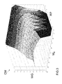
- control law CL consists of an experimental map (i.e. a table or rather a matrix) (which, as is clear in figure 3 , is strongly non-linear); alternatively, the control law CL may consist of a mathematical function.
- the control law CL is stored to a memory of the electronic control unit 21 to be used as described hereafter.
- the electronic control unit 21 measures the actual supercharging pressure P (i.e. the air pressure along the intake conduit 6 downstream of compressor 14), measures or estimates (in a known manner) the pressure upstream of compressor 14 (which may or may not coincide with the atmospheric pressure P atm ) and estimates (in known manner) the actual reduced mass flow rate M R of compressor 14. Furthermore, during the normal operation of the internal combustion engine 1, the electronic control unit 21 determines in a known manner an objective supercharging pressure P obj that must be pursued by controlling, if necessary, the solenoid valve 35 controlling the wastegate valve 16. In order to control the solenoid valve 35 controlling the wastegate valve 16, the electronic control unit 21 determines an objective position WG obj of the solenoid valve 35 controlling the wastegate valve 16 which is generally implemented with an open loop control.
- the objective position WG obj of the solenoid valve 35 controlling the wastegate valve 16 is calculated by algebraically (i.e. taking the sign into account) adding four contributions: an open loop contribution WG OL , a closed loop contribution WG CL1 , a closed loop contribution WG CL2 , and an adaptive contribution WG A .
- the open loop contribution WG OL is determined using the control law CL: an objective compression ratio RP obj (which is equal to the ratio between the objective supercharging pressure P obj and the pressure upstream of compressor 14 which may or may not coincide with the atmospheric pressure P ATM ) is determined as a function of the objective supercharging pressure P obj ; then, the objective compression ratio RP obj and the actual reduced mass flow rate M R are provided to a calculation block 37 which, using the control law CL, provides the open loop contribution WG OL .
- an objective compression ratio RP obj (which is equal to the ratio between the objective supercharging pressure P obj and the pressure upstream of compressor 14 which may or may not coincide with the atmospheric pressure P ATM ) is determined as a function of the objective supercharging pressure P obj ; then, the objective compression ratio RP obj and the actual reduced mass flow rate M R are provided to a calculation block 37 which, using the control law CL, provides the open loop contribution WG OL
- the objective compression ratio RP obj is filtered by means of a low-pass filter 38 of the first order to reduce the variation rate; in other words, the objective compression ratio RP obj is filtered by means of the low-pass filter 38 so as to slow down the evolution of the objective compression ratio RP obj , thus "smoothing" any step changes.
- the function of the low-pass filter 38 is to make the evolution of the objective compression ratio RP obj more "real" (i.e. more adherent to what occurs in reality), since it is clear that step (or in any case very fast) changes in the actual supercharging pressure P are not possible due to obvious physical limits due to the inertia involved.
- a cutoff frequency of the low-pass filter 38 is determined as a function of the reduced mass flow rate M R of compressor 14 and of the actual supercharging ratio RP according to a law determined experimentally.
- the open loop contribution WG OL provided by the calculation block 37 is first compensated by means of three compensation parameters K atm , K H2O and K air and is then filtered through a low-pass filter 39 of the first order to reduce the variation rate.
- the compensation parameter K air is determined by a calculation block 40 as a function of the temperature T air of the intake air and using a linear equation having experimentally determined coefficients
- the compensation parameter K H2O is determined by a calculation block 41 as a function of the temperature T H2O of a cooling liquid of the internal combustion engine 1 and using a linear equation having experimentally determined coefficients
- the compensation parameter K atm is determined by a calculation block 42 as a function of the pressure upstream of compressor 14 (which may or may not coincide with the atmospheric pressure P atm ) and using a linear equation having experimentally determined coefficients
- the coefficients of the linear equation which provides the compensation parameter K atm as a function of the pressure upstream of compressor 14 may not be constant but vary as a function of the reduced mass flow rate M R of compressor 14 and of the actual supercharging ratio RP according to a law determined experimentally.
- the open loop contribution WG OL is filtered by means of the low-pass filter 39 so as to slow down the evolution of the open loop contribution WG OL thus "smoothing" any step changes.
- the function of the low-pass filter 39 is to make the evolution of the open loop contribution WG OL more "real" (i.e. more adherent to what occurs in reality), since it is clear that step (or in any case very fast) changes in the position of the control solenoid valve 35 are not possible due to obvious physical limits due to the inertia involved.
- a cutoff frequency of the low-pass filter 39 is determined as a function of the actual supercharging ratio RP according to a law determined experimentally.
- the open loop contribution WG OL is filtered by means of the low-pass filter 39 asymmetrically: the open loop contribution WG OL is filtered by means of the low-pass filter 39 only when the open loop contribution WG OL varies to open the wastegate valve 16 and not when the open loop contribution WG OL varies to close the wastegate valve 16; in this way, the intervention of compressor 14 is faster (more reactive), thus favoring the response promptness of the internal combustion engine 1 (thus reducing the "turbo-lag") while the switching off of compressor 14 is smoother.
- the closed loop contribution WG CL1 of the objective position WG obj of the controlling solenoid valve 35 controlling the wastegate valve 16 is obtained by using as a feedback variable a fictitious position WGF of the wastegate valve 16 (thus a control magnitude which has no precise correspondence in physical reality) which is determined not by a direct measurement with an actual measurement sensor but using as a sensor measuring the control law CL.
- a calculation block 43 provides the fictitious position WGF of the wastegate valve 16 by applying the control law CL as a function of the actual supercharging pressure P (or rather the actual supercharging ratio RP) and of the reduced mass flow rate M R of compressor 14; therefore, the fictitious position WGF of the wastegate valve 16 corresponding to the position that the wastegate valve 16 should have according to the control law CL (and thus affected by all the errors of the control law CL) in conjunction with the actual supercharging ratio RP and the actual reduced mass flow rate M R of compressor 14.
- the fictitious position WGF of the wastegate valve 16 is compared with the open loop contribution WG OL that corresponds to the position that the wastegate valve 16 should have according to the control law CL (and thus affected by all the errors of the control law CL) in conjunction with the objective compression ratio RP obj and the actual reduced mass flow rate M R of compressor 14; in other words, the open loop contribution WG OL represents an objective of the fictitious position WGF as it is calculated using the objective compression ratio RP obj .
- a position error ⁇ WG is calculated by calculating the difference between the open loop contribution WG OL of the objective position WG obj of the solenoid valve 35 controlling the wastegate valve 16 and the fictitious position WGF of the wastegate valve 16 and such a position error ⁇ WG is provided to a PID regulator 44 which tries to cancel the position error ⁇ WG itself.
- the PID regulator 44 may work with greater stability and the calibration of the control parameters (i.e. proportional, integrative, derivative coefficients and saturation thresholds) of the PID regulator 44 is relatively simple. Furthermore, the control loop of the PID regulator 44 is self-compensated with respect to the temperature T air of the intake air, the temperature T H2O of a cooling liquid of the internal combustion engine 1, and the atmospheric pressure P atm .
- the closed loop contribution WG CL2 of the objective position WG obj of the solenoid valve 35 controlling the wastegate valve 16 is determined by using the supercharging pressure P as feedback variable; then, a pressure error ⁇ P is calculated by calculating the difference between the objective supercharging pressure P obj and the actual supercharging pressure P and the pressure error ⁇ WG is provided to a PID regulator 45 which tries to cancel the pressure error ⁇ WG itself.
- the objective supercharging pressure P obj is filtered by means of a low-pass filter 46 of the first order to reduce the variation rate; in other words, the objective supercharging pressure P obj is filtered by means of the low-pass filter 46 so as to slow down the evolution of the objective supercharging pressure P obj, thus "smoothing" any step changes.
- the function of the low-pass filter 46 is to make the evolution of the objective supercharging pressure P obj more "real" (i.e.
- a cutoff frequency of the low-pass filter 46 is determined as a function of the reduced mass flow rate M R of compressor 14 and of the actual supercharging ratio RP according to a law determined experimentally.
- regulator 44 is essentially proportional and derivative (i.e. has high proportional and derivative coefficients and a small integral coefficient) in order to be ready (i.e. act quickly) while regulator 45 is essentially integral (i.e. has small proportional and derivative coefficients and a high integral coefficient) to ensure the convergence between the objective supercharging pressure P obj and the actual supercharging pressure P.
- regulator 44 is used to react quickly and promptly to the variations in the objective supercharging pressure P obj , while regulator 45 is used to make the actual supercharging pressure P converge to the objective supercharging pressure P obj at the end of the transient.
- the adaptive contribution WG A of the objective position WG obj of the solenoid valve 35 controlling the wastegate valve 16 is essentially a "historical memory" of the previous implementations of the wastegate valve 16 and takes into account the control interventions carried out in the past.
- the adaptive contribution WG A is stored to a memory 47 of the electronic control unit 21 and is cyclically updated when turbocharger 12 is at a steady speed (for example when the reduced mass flow rate M R of compressor 14 and the supercharging ratio RP remain approximately constant for at least a time interval of predetermined duration) and using an integral term of the PID regulator 45 and/or of the PID regulator 44; basically, the adaptive contribution WG A is equal to an "average" of the past integral terms of the PID regulator 45 and/or of the PID regulator 44 at steady schemes of turbocharger 12.
- the adaptive contribution WG A stored to memory 47 is updated when turbocharger 12 is at a steady speed, using the integral term of the PID regulator 45 and/or of the PID regulator 44 weighed by means of a weight W which is essentially a function of the actual position WG of the solenoid valve 35 controlling the wastegate valve 16 in such a way that weight W is minimum when the hysteresis in the control of the wastegate valve 16 is maximum; in this way, the adaptivity is always gradual (i.e. the last integral term of the PID regulator 45 and/or of the PID regulator 44 cannot alter the adaptive contribution WG A stored to memory 47), and uploading hysteresis-deformed values to the adaptive contribution WG A is prevented.
- the adaptive contribution WG A is variable as a function of the reduced mass flow rate M R of compressor 14 and of the supercharging ratio RP.
- the adaptive contribution WG A is filtered by means of a low-pass filter 48 of the first order to reduce the variation rate; in other words, the adaptive contribution WG A is not provided abruptly but is provided gradually to prevent step interventions which never correspond to the physical reality and thus to facilitate the control convergence.
- the cutoff frequency of the low-pass filter 48 is constant; alternatively, the cutoff frequency of the low-pass filter 48 may be varied as a function of the reduced mass flow rate M R of compressor 14 and of the supercharging ratio RP.
- the integral term of the PID regulators 44 and 45 contains a "memory" of the errors that have occurred in the recent past; therefore, when changes occur in boundary conditions, the "memory" of the errors that have occurred in the recent past contained in the integral term of the PID regulators 44 and 45 may have negative effects as it is a situation that no longer exists.
- the electronic control unit 21 resets (or possibly “freezes”, i.e. prevents a further growth of) each integral term of the PID regulators 44 and 45 in case of rapid variation, i.e. strong transient, of the objective supercharging pressure P obj if the integral term itself is high, that is, is higher in absolute value than a predefined threshold value; in other words, when there is a rapid variation in the objective supercharging pressure P obj and an integral term of the PID regulators 44 and 45 is higher in absolute value than a predefined threshold value, then the integral term itself is reset or frozen (i.e. is no longer made to vary until the end of strong transient).
- the electronic control unit 21 compares the objective supercharging pressure P obj with an objective supercharging pressure P obj-F filtered by means of a low-pass filter 38' to determine a gradient ⁇ P obj of the objective supercharging pressure P obj which indicates the variation rate of the objective supercharging pressure P obj .
- the gradient ⁇ P obj of the objective supercharging pressure P obj is calculated by calculating the difference between the objective supercharging pressure P obj and the objective supercharging pressure P obj-F filtered by means of the low-pass filter 38'.
- the electronic control unit 21 establishes the presence of a strong transient of the objective supercharging pressure P obj (i.e.
- a cutoff frequency of the low-pass filter 38' is determined as a function of the reduced mass flow rate M R of compressor 14 and of the actual supercharging ratio RP according to a law determined experimentally.
- the electronic control unit 21 varies the integral coefficients of the PID regulators 44 and 45 as a function of the pressure error ⁇ P , so as to vary the characteristics of the control upon the variation of the extent of the pressure error ⁇ P .
- the electronic control unit 21 varies the integral coefficients of the PID regulators 44 and 45 in a manner inversely proportional to the pressure error ⁇ P in such a way that the smaller the pressure error ⁇ P , the higher the integral coefficients of the PID regulators 44 and 45, and varies the proportional coefficients of the PID regulators 44 and 45 in a manner directly proportional to the pressure error ⁇ P in such a way that the higher the pressure error ⁇ P , the higher the proportional coefficients of the PID regulators 44 and 45.
- the integral term of the PID regulators 44 and 45 (directly proportional to the integral coefficients of the PID regulators 44 and 45) serves to guarantee the convergence between the actual supercharging pressure P and the objective supercharging pressure P obj but such a convergence is reached at the end of a transient when the pressure error ⁇ P is relatively small; at the beginning of the transient, when the pressure error ⁇ P is high, the integral term of the PID regulators 44 and 45 may generate oscillations and therefore, in order to prevent this risk, the integral coefficients of the PID regulators 44 and 45 are reduced at the beginning of the transient when the pressure error ⁇ P is high.
- the cutoff frequency is determined as a function of the reduced mass flow rate M R of compressor 14 and of the actual supercharging ratio RP; according to an equivalent embodiment, the cutoff frequency is determined as a function of the rotation speed of the internal combustion engine 1 and as a function of a gear engaged in a gearbox which receives motion from the internal combustion engine 1.
- turbocharger 12 varies substantially as a function of the gear engaged, since in the lower gears the increase in the rotation speed of the internal combustion engine 1 is fast, thus the increase in the rotation speed of turbocharger 12 is equally rapid; on the other hand, in higher gears the increase in the rotation speed of the internal combustion engine 1 is slow, so the increase in the rotation speed of turbocharger 12 is just as slow.
- the threshold value with which the gradient ⁇ P obj of the objective supercharging pressure P obj is compared to determine whether there is a strong transient of the objective supercharging pressure P obj may be a function of the reduced mass flow rate M R of compressor 14 and of the actual supercharging ratio RP or it may be a function of the rotation speed of the internal combustion engine 1 of a gear engaged in a gearbox which receives motion from the internal combustion engine 1.
- the supercharging pressure P and the supercharging ratio RP are perfectly equivalent to each other, since the pressure upstream of compressor 14 (which may or may not coincide with the atmospheric pressure P atm ) is approximately constant and has a value around the unit value; then, using the supercharging ratio RP is equivalent to using the supercharging pressure P and vice versa.
- the supercharging ratio RP is used but according to an equivalent embodiment not shown, the supercharging pressure P may be used instead of the supercharging ratio RP.
- the control law CL provides an objective opening WG of the solenoid valve 35 controlling the wastegate valve 16 as a function of a supercharging pressure P (or rather a supercharging ratio RP which is equal to the ratio between the supercharging pressure P and the pressure upstream of compressor 14 which may or may not coincide with the atmospheric pressure P atm ) and of a reduced mass flow rate M R of compressor 14; according to an equivalent embodiment, the control law CL provides an objective opening WG of the solenoid valve 35 controlling the wastegate valve 16 as a function of a power supplied by the internal combustion engine 1 and of a volumetric efficiency of the internal combustion engine 1, or as a function of a rotation speed of the internal combustion engine 1 and of a volumetric efficiency of the internal combustion engine 1 (of course, different combinations of the parameters of the internal combustion engine 1 are also possible).
- the electronic control unit 21 is further suited to control the supercharged internal combustion engine 1 so as to reduce as much as possible the phenomenon known as turbo lag, i.e. the delay in the response of the supercharging by turbocharger 12.
- the electronic control unit 21 is suited to control the supercharged internal combustion engine 1 for operating in "scavenging" mode, in which a significant air flow is provided from the intake manifold 4 directly into the exhaust conduit 10 of the internal combustion engine 1.
- the air flow from the intake manifold 4 directly into the exhaust conduit 10 is implemented by means of a suitable timing of the intake valves (not shown) which connect each cylinder 3 to the intake manifold 4 and of the exhaust valves (not shown) which connect each cylinder 3 to the exhaust manifold 5 to allow the flow of fresh air directly from the intake manifold 4 to the exhaust manifold 5 and hence in the exhaust conduit 10 of the internal combustion engine 1.
- the electronic control unit 21 is further suited to control the supercharged internal combustion engine 1 so as to increase the mass and volume flow rate of air and/or exhaust gases which flow through compressor 14 and turbine 13, with respect to the air flow rate actually used by the supercharged internal combustion engine 1 in combustion to generate the desired power.
- the electronic control unit 21 is suited to differentiate the management of cylinders 3, in particular, to differentiate the flow rate of the intake air and of the air trapped in each cylinder 3, and to differentiate the mode of operation.
- the electronic control unit 21 is suited to generate the objective torque required by the vehicle's driver with only a part of cylinders 3 in combustion, while the remaining cylinders 3 draw as much air as possible.
- two cylinders 3 are active and produce the desired torque by drawing a mass of air that is approximately twice the mass of air they would draw in normal operating conditions (that is to say, if all four cylinders 3 were active).
- the remaining two cylinders 3 are not active and are controlled to draw the maximum air but are not involved in the combustion. Since the mass of air that flows through the two non active cylinders does not participate in the combustion, it flows directly from the intake manifold to the exhaust.
- the open loop contribution WG OL in the calculation block 37 allows obtaining an open loop contribution WG OL corrected as a function of the "scavenging" mode, in which a significant air flow is provided from the intake manifold 4 directly into the exhaust conduit 10 of the internal combustion engine 1.
- the contribution WG NOSCAV in the absence of the "scavenging" mode i.e. in the absence of a significant air flow from the intake manifold 4 directly into the exhaust conduit 10 of the internal combustion engine 1, is determined in the calculation block 49.
- An objective compression ratio RP obj (which is equal to the ratio between the objective supercharging pressure P obj and the pressure upstream of compressor 14 which may or may not coincide with the atmospheric pressure P atm ) is determined as a function of the objective supercharging pressure; then, the objective compression ratio and the actual reduced mass flow rate M R are provided to the calculation block 49 which provides the contribution WG NOSCAV in the absence of the "scavenging" mode.
- the contribution WG MAXSCAV in maximum "scavenging" mode conditions i.e. when the air flow from the intake manifold 4 directly into the exhaust conduit 10 of the internal combustion engine 1 is the maximum possible, is determined in the calculation block 50.
- An objective compression ratio RP obj (which is equal to the ratio between the objective supercharging pressure P obj and the pressure upstream of compressor 14 which may or may not coincide with the atmospheric pressure P atm ) is determined as a function of the objective supercharging pressure; then, the objective compression ratio and the actual reduced mass flow rate M R are provided to a calculation block 50 which provides the contribution WG MAXSCAV in maximum "scavenging" mode conditions.
- the contribution WG MAXSCAV in maximum "scavenging" mode conditions thus corresponds to the position that the wastegate valve 16 should have according to the control law CL (thus affected by all the errors of the control law CL) in conjunction with the maximum air flow from the intake manifold 4 directly into the exhaust conduit 10 of the internal combustion engine 1.
- the contribution WG NOSCAV in the absence of the "scavenging” mode is compared with the contribution WG MAXSCAV in maximum “scavenging” mode conditions.
- a "scavenging" contribution ⁇ SCAV is calculated by calculating the difference between the contribution WG MAXSCAV in maximum “scavenging” mode conditions and the contribution WG NOSCAV in the absence of "scavenging” mode and such a “scavenging” contribution ⁇ SCAV is provided to a calculation block 51.
- the efficiency ⁇ SCAV_MAX in maximum "scavenging" mode conditions i.e. when the air flow from the intake manifold 4 directly into the exhaust conduit 10 of the internal combustion engine 1 is maximum, is determined in the calculation block 52.
- An objective compression ratio RP obj (which is equal to the ratio between the objective supercharging pressure P obj and the pressure upstream of compressor 14 which may or may not coincide with the atmospheric pressure P atm ) is determined as a function of the objective supercharging pressure; then, the objective compression ratio and the actual reduced mass flow rate M R are provided to a calculation block 52 which provides the efficiency ⁇ SCAV_MAX in maximum "scavenging" mode conditions.
- the efficiency ⁇ SCAV_MAX in maximum “scavenging” mode conditions is compared with the "scavenging" efficiency ⁇ SCAV of cylinders 3 obtained by the ratio between the mass flow rate m, preferably the reduced mass flow rate, of total air flowing through the internal combustion engine 1 and the mass flow rate m com of air trapped in cylinders 3, which participates in the combustion.
- a relative “scavenging" efficiency ⁇ SCAV_rel obtained from the ratio between the “scavenging efficiency ⁇ SCAV and the efficiency ⁇ SCAV_MAX in maximum “scavenging” mode conditions is calculated and such a “scavenging" efficiency ⁇ SCAV_rel is provided to a calculation block 53.
- a factor f ( ⁇ SCAV_rel ) is determined in block 53 which is a function of the relative "scavenging" efficiency ⁇ SCAV_rel described above.
- the factor f ( ⁇ SCAV_rel ) which is a function of the relative "scavenging" efficiency ⁇ SCAV_rel is compared in the calculation block 51 with the "scavenging" contribution E SCAV .
- an actual contribution WG SCAVeff obtained by the product between factor f ( ⁇ SCAV_rel ) is calculated, which is a function of the relative "scavenging" efficiency ⁇ SCAV_rel and the "scavenging" contribution ⁇ SCAV .
- the actual contribution WG SCAVeff obtained by the product of factor f ( ⁇ SCAV_rel ) and the "scavenging" contribution ⁇ SCAV is an indicator of the quantity of air that flows from the intake manifold 4 directly into the exhaust conduit 10 of the internal combustion engine 1; that is, it represents the contribution in controlling the solenoid valve 35 controlling the wastegate valve 16 due solely to the "scavenging" mode.
- the actual contribution WG SCAVeff in "scavenging" mode conditions is determined in the calculation block 51 and then added in the calculation block 54 to the contribution WG NOSCAV in the absence of the "scavenging" mode to obtain the open loop contribution WG OL in the calculation block 37.
- Figure 6 shows a block diagram totally similar to the block diagram in figure 5 which provides the open loop contribution WG OL in the calculation block 37 and where possible, common parts are indicated with the same reference numerals.
- Figure 6 comprises a calculation block 55 which determines the rotation speed N t of turbocharger 12 starting from some characteristic maps, which are typically provided by the manufacturer of turbocharger 12, as a function of the objective compression ratio RP obj and of the actual reduced mass flow rate M R .
- an objective compression ratio RP obj (which is equal to the ratio between the objective supercharging pressure P obj and the pressure upstream of compressor 14 which may or may not coincide with the atmospheric pressure P atm ) is determined as a function of the objective supercharging pressure; then, the objective compression ratio RP obj and the actual reduced mass flow rate M R are provided to the calculation block 55 which provides the rotation speed N t of turbocharger 12.
- Such a rotation speed N t of turbocharger 12 is provided to a calculation block 53'.
- the relative "scavenging" efficiency ⁇ SCAV_rel obtained from the ratio between the efficiency ⁇ SCAV_MAX in maximum “scavenging” mode conditions and the “scavenging” efficiency ⁇ SCAV is provided to the calculation block 53' together with the rotation speed N t of turbocharger 12.
- a factor f ( ⁇ SCAV_rel, N t ) is determined in the calculation block 53' which is a function of both the relative "scavenging" efficiency ⁇ SCAV_rel, i.e. the ratio between the efficiency ⁇ SCAV_MAX in maximum “scavenging” mode conditions and the “scavenging” efficiency ⁇ SCAV , and of the rotation speed N t of turbocharger 12.
- the above method for determining the open loop contribution WG OL in the calculation block 37 may be used in combination with the method of correction of the reduced mass flow rate Mr of a compressor 14 in a turbocharged internal combustion engine 1 described in patent application BO2013A000480 , entirely incorporated herein by reference.
- control law CL described above further allows using the open loop contribution WG OL of the objective position WG obj of actuator 35 controlling the wastegate valve 16 obtained in the calculation block 37 for determining the closed loop contribution WG CL1 .
- control law CL described above is used in the calculation block 43 to provide the fictitious position WGF of the wastegate valve 16 which is in turn used to determine the closed loop contribution WG CL1 .
- the control law CL used in the calculation block 43 differs from the control law CL used in block 37 only in that the actual supercharging pressure P or rather the actual supercharging ratio RP is used instead of the objective compression ratio RP obj .
- the above method for determining the open loop contribution WG OL in the calculation block 37 has several advantages.
- it allows calculating an open loop contribution WG OL corrected as a function of the "scavenging" mode, i.e. as a function of the quantity of air that actually flows from the intake manifold 4 directly into the exhaust conduit 10 of the internal combustion engine 1 in an effective way but, at the same time, it is simple and cost-effective to be implemented in an electronic control unit 21 of an internal combustion engine 1 as it uses measurements provided by sensors which are always present in modern internal combustion engines 1 and does require neither a large computing capacity nor a large memory.
- the above method of calculating the open loop contribution WG OL corrected as a function of the "scavenging" mode allows making the control of the wastegate valve 16 sturdy, ready and free from oscillations in all operating conditions; in particular, also in the operating condition in which there is a significant air flow from the intake manifold directly to the exhaust of the internal combustion engine 1.
Landscapes
- Engineering & Computer Science (AREA)
- Chemical & Material Sciences (AREA)
- Combustion & Propulsion (AREA)
- Mechanical Engineering (AREA)
- General Engineering & Computer Science (AREA)
- Supercharger (AREA)
Abstract

Description
- The present invention relates to a method to control a wastegate valve in an internal combustion engine turbocharged by means of a turbocharger.
- As is known, some internal combustion engines are provided with a turbochargher supercharging system which is able to increase the power developed by the engine by exploiting the enthalpy of exhaust gases for compressing the air drawn by the engine and thus increase the volumetric efficiency of the intake.
- A turbochargher supercharging system comprises a turbocharger provided with a turbine, which is arranged along an exhaust conduit for rotating at high speed under the thrust of the exhaust gases expelled from the engine, and a compressor, which is brought in rotation by the turbine and is arranged along the air supply conduit to compress the air drawn by the engine. In a turbochargher supercharging system it is necessary to maintain the operating range of the turbocharger within a useful zone depending on the engine point both for functional reasons (i.e. to prevent irregular operation or in any case low efficiency), and for structural reasons (i.e. to prevent damage to the turbocharger). In order to limit the supercharging pressure (i.e. the pressure of the compressed air downstream of the compressor), a by-pass conduit controlled by a wastegate valve is arranged in parallel to the turbine; when the wastegate valve opens, a part of the exhaust gases flows along the by-pass conduit, and thus by-passes the turbine, and this leads to a reduction in the rotation speed of the impeller and, thereby, to a a reduction in the supercharge.
- In order to control the wastegate valve, a pneumatic actuator controlled by a control solenoid valve is used which allows controlling the intervention of the wastegate valve. The pneumatic actuator comprises a sealed shell which internally supports a flexible membrane, which divides the sealed shell in two mutually watertight chambers. The flexible membrane is mechanically connected to a rigid rod which controls the wastegate valve for controlling the opening and closing of the wastegate valve itself. A first chamber is connected to the atmospheric pressure while a second chamber is connected to the supercharging pressure and is also connectable to the atmospheric pressure through a conduit controlled by the proportional control solenoid valve which is adapted to choke the conduit between a closed position, in which the conduit is completely closed, and a maximum opening position.
- A contrast spring is arranged in the first chamber which is compressed between a wall of the shell and the
flexible membrane 28 and leans on the flexible membrane on the opposite side of the rod. When the pressure difference between the two chambers is lower than an intervention threshold (determined by the preload of the contrast spring), the rod keeps the wastegate valve in a fully closed position, while when the pressure difference between the two chambers is higher than the intervention threshold, the contrast spring starts to compress under the thrust of the flexible membrane which thus gets deformed, causing a displacement of the rod which accordingly moves the wastegate valve towards the opening position. By controlling the control solenoid valve it is possible to connect the second chamber to the atmospheric pressure with a variable passage gap, thus it is possible to adjust the pressure difference between the two chambers which, in turn, causes the opening or closing of the wastegate valve. It should be noted that until the difference between the supercharging pressure and the atmospheric pressure does not exceed the intervention threshold (equal to the preload generated by the contrast spring divided by the flexible membrane area), the wastegate valve cannot be opened by the action that is exerted by the control solenoid valve (which can only reduce and not increase the difference between the supercharging pressure and the atmospheric pressure). - In internal combustion engines known, an objective supercharging pressure is generated which is used to generate a control of the wastegate valve by adding an open loop contribution and a closed loop contribution: the open loop contribution is generated by using a control map obtained experimentally while the closed loop contribution is provided by a PID regulator which tries to cancel a pressure error, i.e. a difference between the objective supercharging pressure and the actual supercharging pressure measured by a sensor.
- However, the preload generated by the contrast spring of the pneumatic actuator has a high construction dispersion, a considerable thermal drift, and also a certain time drift. Furthermore, the pneumatic actuator has a considerable hysteresis, i.e. the behavior of the pneumatic actuator significantly varies between the opening movement and the contrary closing movement. Accordingly, the control map used for determining the closed loop contribution is strongly non-linear and the pursuing of the objective supercharging pressure is complicated; therefore, in known internal combustion engines, pursuing the objective supercharging pressure tends to have large overshoots or undershoots (i.e. the actual supercharging pressure exceeds or is even considerably lower than the objective supercharging pressure), and thus generate oscillations, especially when the supercharging pressure is astride the intervention threshold below which the wastegate valve cannot be opened by the action exerted by the control solenoid valve.
- Overshoots (i.e. peaks) of the supercharging pressure are particularly annoying since they cause significant (and therefore potentially harmful in time) stresses in the mechanical components of the internal combustion engine and since they may generate both a noise perceptible by the occupants of the vehicle, and corresponding undesired oscillations in the drive torque generated by the internal combustion engine.
- In order to reduce the extent of overshoots, it is possible to reduce the additional contribution of the PID regulator used to calculate the closed loop control contribution of the wastegate valve.
- For example, patent
EP2314850 describes a method for controlling the wastegate valve comprising the steps of determining, in a design step, a control law which provides an objective opening of an actuator controlling the wastegate valve as a function of a supercharging pressure; determining an objective supercharging pressure; measuring an actual supercharging pressure; determining a first open loop contribution of an objective position of the actuator controlling the wastegate valve by the control law and as a function of the objective supercharging pressure; determining a second closed loop contribution of the objective position of the actuator controlling the wastegate valve; calculating the objective position of the actuator controlling the wastegate valve by adding the two contributions; and controlling the actuator controlling the wastegate valve for pursuing the objective position of the actuator controlling the wastegate valve. - Wherein the step of determining the second closed loop contribution provides for determining a fictitious position of the actuator controlling the wastegate valve by the control law and as a function of the actual supercharging pressure; calculating a position error by calculating the difference between the first open loop contribution of the objective position of the actuator controlling the wastegate valve and the fictitious position of the actuator controlling the wastegate valve; and determining the second closed loop contribution by processing the position error by a first regulator which tries to cancel the position error itself.
- However, the control method described in patent
EP2314850 is quite robust, ready and free from oscillations only in the operating condition in which there is no significant air flow from the intake manifold directly to the exhaust of theinternal combustion engine 1. - The object of the present invention is to provide a method to control a wastegate valve in an internal combustion engine turbocharged by means of a turbocharger, which correction method is free from the drawbacks described above and, in particular, is easy and cost-effective to be implemented.
- According to the present invention, a method to control a wastegate valve in an internal combustion engine turbocharged by means of a turbocharger is provided according to the accompanying claims.
- The present invention will now be described with reference to the accompanying drawings, which show a non-limiting example thereof, in which:
-
f igure 1 is a schematic view of an internal combustion engine supercharged by means of a turbocharger and provided with a control unit which implements the method to control a wastegate valve object of the present invention; -
f igure 2 is a schematic view of a pneumatic actuator of the wastegate valve; - f igure 3 is a graph showing an experimental control map; and
-
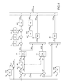
f igures 4 to 6 are block diagrams of a control logic of the wastegate valve. - In
figure 1 ,reference numeral 1 globally indicates an internal combustion engine supercharged by means of aturbocharger supercharging system 2. - The
internal combustion engine 1 comprises four cylinders 3, each of which is connected to anintake manifold 4 by means of at least one respective intake valve (not shown) and to anexhaust manifold 5 by means of at least one respective exhaust valve (not shown). Theintake manifold 4 receives fresh air (i.e. air from the external environment) through anintake conduit 6, which is provided with anair filter 7 and is controlled by athrottle valve 8. Anintercooler 9 having the function of cooling the intake air is arranged along theintake conduit 6. Anexhaust conduit 10 is connected to theexhaust manifold 5 which feeds the exhaust gases produced by the combustion to an exhaust system, which releases the gases produced by combustion into the atmosphere and normally comprises at least onecatalyst 11 and at least one silencer (not shown) arranged downstream ofcatalyst 11. - The
supercharging system 2 of theinternal combustion engine 1 comprises aturbocharger 12 provided with aturbine 13, which is arranged along theexhaust conduit 10 to rotate at high speed under the action of the exhaust gases ejected through cylinders 3, and acompressor 14, which is arranged along theintake conduit 6 and is mechanically connected toturbine 13 to be rotated byturbine 13 itself so as to increase the pressure of the air fed in thefeeding conduit 6. - A by-
pass conduit 15 is provided along theexhaust conduit 10, which is connected in parallel toturbine 13 so as to have the ends thereof connected upstream and downstream ofturbine 13 itself; awastegate valve 16 is arranged along the by-pass conduit 15, which is adapted to control the flow rate of the exhaust gases flowing through the by-pass conduit 15 and is controlled by apneumatic actuator 17. A by-pass conduit 18 is provided along theintake conduit 6, which is connected in parallel tocompressor 14 so as to have the ends thereof connected upstream and downstream ofcompressor 14 itself; avalve Poff 19 is arranged along the by-pass conduit 18, which is adapted to control the air flow rate flowing through the by-pass conduit 18 and is controlled by anelectrical actuator 20. - The
internal combustion engine 1 is controlled by anelectronic control unit 21, which supervises the operation of all components of theinternal combustion engine 1, among which thesupercharging system 2. In particular, theelectronic control unit 21 controlsactuators wastegate valve 16 and of thePoff valve 19. Theelectronic control unit 21 is connected tosensors 22 which measure the temperature and the pressure along theintake conduit 6 upstream ofcompressor 14, tosensors 23 which measure the temperature and the pressure along theintake conduit 6 upstream of thethrottle valve 8, and tosensors 24 which measure the temperature and the pressure inside theintake manifold 4. Moreover, theelectronic control unit 21 is connected to asensor 25 which measures the angular position (and thus the rotation speed) of a drive shaft of theinternal combustion engine 1 and asensor 26 which measures the phase of the intake and/or exhaust valves. - As shown in
figure 2 , thepneumatic actuator 17 of thewastegate valve 16 comprises a sealedshell 27 which internally supports aflexible membrane 28, which divides the sealedshell 27 into two mutually isolatedchambers flexible membrane 28 is mechanically connected to arigid rod 31 which controls thewastegate valve 16 for controlling the opening and closing of thewastegate valve 16 itself.Chamber 29 is connected by aconduit 32 to the pressure upstream of compressor 14 (which may or may not coincide with the atmospheric pressure PATM), whilechamber 30 is connected by aconduit 33 to the supercharging pressure (drawn downstream of compressor 14) and is connected by aconduit 34 to the pressure upstream of compressor 14 (which may or may not coincide with the atmospheric pressure Patm).Conduit 34 is not free but is controlled by acontrol solenoid valve 35 which is adapted tochoke conduit 34 between a closed position, in whichconduit 34 is completely closed, and a maximum opening position. - A
contrast spring 36 is arranged inchamber 29 which is compressed between a wall ofshell 27 and theflexible membrane 28 and leans on theflexible membrane 28 on the opposite side ofrod 31. When the pressure difference betweenchamber 30 andchamber 29 is lower than an intervention threshold (determined by the preload of the contrast spring 36),rod 31 keeps thewastegate valve 16 in a fully closed position, while when the pressure difference betweenchamber 30 andchamber 29 is higher than the intervention threshold, thecontrast spring 36 starts to compress under the thrust of theflexible membrane 28 which thus gets deformed, causing a displacement ofrod 31 which accordingly moves thewastegate valve 16 towards the opening position. By controlling thecontrol solenoid valve 35 it is possible to connectchamber 30 to the atmospheric pressure with a variable passage gap, thus it is possible to adjust the pressure difference between the twochambers wastegate valve 16. - It should be noted that until the difference between the supercharging pressure P and the pressure upstream of compressor 14 (which may or may not coincide with the atmospheric pressure Patm) does not exceed the intervention threshold (equal to the preload generated by the
contrast spring 36 divided by theflexible membrane 28 area), thewastegate valve 16 cannot be opened by the action that is exerted by the control solenoid valve 35 (which can only reduce and not increase the difference between the supercharging pressure P and the pressure upstream ofcompressor 14 which may or may not coincide with the atmospheric pressure Patm). Due to the construction dispersion, to the thermal drift, and to the time drift, the preload generated by thecontrast spring 36 is known only with a quite relevant uncertainty (in the order of ±20%). - In a design step of the
internal combustion engine 1, a control law CL is determined experimentally which provides an objective opening WG of thesolenoid valve 35 controlling thewastegate valve 16 as a function of a supercharging pressure P (or rather a supercharging ratio RP which is equal to the ratio between the supercharging pressure P and the pressure upstream ofcompressor 14, which may or may not coincide with the atmospheric pressure Patm) and a reduced mass flow rate MR ofcompressor 14. In other words, the control law CL provides the opening WG of thesolenoid valve 35 controlling thewastegate valve 16 which should allow obtaining a desired supercharging pressure P (or rather a desired supercharging ratio RP) in the presence of a certain reduced mass flow rate MR. According to a preferred embodiment shown for example infigure 3 , the control law CL consists of an experimental map (i.e. a table or rather a matrix) (which, as is clear infigure 3 , is strongly non-linear); alternatively, the control law CL may consist of a mathematical function. The control law CL is stored to a memory of theelectronic control unit 21 to be used as described hereafter. - In use, during the normal operation of the
internal combustion engine 1, theelectronic control unit 21 measures the actual supercharging pressure P (i.e. the air pressure along theintake conduit 6 downstream of compressor 14), measures or estimates (in a known manner) the pressure upstream of compressor 14 (which may or may not coincide with the atmospheric pressure Patm) and estimates (in known manner) the actual reduced mass flow rate MR ofcompressor 14. Furthermore, during the normal operation of theinternal combustion engine 1, theelectronic control unit 21 determines in a known manner an objective supercharging pressure Pobj that must be pursued by controlling, if necessary, thesolenoid valve 35 controlling thewastegate valve 16. In order to control thesolenoid valve 35 controlling thewastegate valve 16, theelectronic control unit 21 determines an objective position WGobj of thesolenoid valve 35 controlling thewastegate valve 16 which is generally implemented with an open loop control. - As shown in
figure 4 , the objective position WGobj of thesolenoid valve 35 controlling thewastegate valve 16 is calculated by algebraically (i.e. taking the sign into account) adding four contributions: an open loop contribution WGOL, a closed loop contribution WGCL1, a closed loop contribution WGCL2, and an adaptive contribution WGA. - The open loop contribution WGOL is determined using the control law CL: an objective compression ratio RPobj (which is equal to the ratio between the objective supercharging pressure Pobj and the pressure upstream of
compressor 14 which may or may not coincide with the atmospheric pressure PATM) is determined as a function of the objective supercharging pressure Pobj; then, the objective compression ratio RPobj and the actual reduced mass flow rate MR are provided to acalculation block 37 which, using the control law CL, provides the open loop contribution WGOL. - Preferably, before being provided to the
calculation block 37, the objective compression ratio RPobj is filtered by means of a low-pass filter 38 of the first order to reduce the variation rate; in other words, the objective compression ratio RPobj is filtered by means of the low-pass filter 38 so as to slow down the evolution of the objective compression ratio RPobj, thus "smoothing" any step changes. The function of the low-pass filter 38 is to make the evolution of the objective compression ratio RPobj more "real" (i.e. more adherent to what occurs in reality), since it is clear that step (or in any case very fast) changes in the actual supercharging pressure P are not possible due to obvious physical limits due to the inertia involved. According to a preferred embodiment, a cutoff frequency of the low-pass filter 38 is determined as a function of the reduced mass flow rate MR ofcompressor 14 and of the actual supercharging ratio RP according to a law determined experimentally. - According to a preferred embodiment, the open loop contribution WGOL provided by the
calculation block 37 is first compensated by means of three compensation parameters Katm, KH2O and Kair and is then filtered through a low-pass filter 39 of the first order to reduce the variation rate. The compensation parameter Kair is determined by acalculation block 40 as a function of the temperature Tair of the intake air and using a linear equation having experimentally determined coefficients, the compensation parameter KH2O is determined by acalculation block 41 as a function of the temperature TH2O of a cooling liquid of theinternal combustion engine 1 and using a linear equation having experimentally determined coefficients, and the compensation parameter Katm is determined by acalculation block 42 as a function of the pressure upstream of compressor 14 (which may or may not coincide with the atmospheric pressure Patm) and using a linear equation having experimentally determined coefficients; the coefficients of the linear equation which provides the compensation parameter Katm as a function of the pressure upstream of compressor 14 (which may or may not coincide with the atmospheric pressure Patm) may not be constant but vary as a function of the reduced mass flow rate MR ofcompressor 14 and of the actual supercharging ratio RP according to a law determined experimentally. - The open loop contribution WGOL is filtered by means of the low-
pass filter 39 so as to slow down the evolution of the open loop contribution WGOL thus "smoothing" any step changes. The function of the low-pass filter 39 is to make the evolution of the open loop contribution WGOL more "real" (i.e. more adherent to what occurs in reality), since it is clear that step (or in any case very fast) changes in the position of thecontrol solenoid valve 35 are not possible due to obvious physical limits due to the inertia involved. According to a preferred embodiment, a cutoff frequency of the low-pass filter 39 is determined as a function of the actual supercharging ratio RP according to a law determined experimentally. According to a preferred embodiment, the open loop contribution WGOL is filtered by means of the low-pass filter 39 asymmetrically: the open loop contribution WGOL is filtered by means of the low-pass filter 39 only when the open loop contribution WGOL varies to open thewastegate valve 16 and not when the open loop contribution WGOL varies to close thewastegate valve 16; in this way, the intervention ofcompressor 14 is faster (more reactive), thus favoring the response promptness of the internal combustion engine 1 (thus reducing the "turbo-lag") while the switching off ofcompressor 14 is smoother. It should be noted that when the maximum performance is sought, an "abrupt" reaction of theinternal combustion engine 1 is accepted (indeed, in some cases desired), while in other situations a "smooth" behavior, i.e. devoid of too rapid and strong interventions, is essentially desired. It should be noted that thanks to the presence of the low-pass filter 39, any oscillatory phenomena in thepneumatic actuator 17 of thewastegate valve 16 are also eliminated or greatly attenuated; this result is achieved by virtue of the fact that the action of the low-pass filter 39 prevents providing theflexible membrane 28 and thecontrast spring 36 with too rapid stresses which may trigger oscillatory phenomena. - The closed loop contribution WGCL1 of the objective position WGobj of the controlling
solenoid valve 35 controlling thewastegate valve 16 is obtained by using as a feedback variable a fictitious position WGF of the wastegate valve 16 (thus a control magnitude which has no precise correspondence in physical reality) which is determined not by a direct measurement with an actual measurement sensor but using as a sensor measuring the control law CL. In other words, acalculation block 43 provides the fictitious position WGF of thewastegate valve 16 by applying the control law CL as a function of the actual supercharging pressure P (or rather the actual supercharging ratio RP) and of the reduced mass flow rate MR ofcompressor 14; therefore, the fictitious position WGF of thewastegate valve 16 corresponding to the position that thewastegate valve 16 should have according to the control law CL (and thus affected by all the errors of the control law CL) in conjunction with the actual supercharging ratio RP and the actual reduced mass flow rate MR ofcompressor 14. The fictitious position WGF of thewastegate valve 16 is compared with the open loop contribution WGOL that corresponds to the position that thewastegate valve 16 should have according to the control law CL (and thus affected by all the errors of the control law CL) in conjunction with the objective compression ratio RPobj and the actual reduced mass flow rate MR ofcompressor 14; in other words, the open loop contribution WGOL represents an objective of the fictitious position WGF as it is calculated using the objective compression ratio RPobj. In particular, a position error εWG is calculated by calculating the difference between the open loop contribution WGOL of the objective position WGobj of thesolenoid valve 35 controlling thewastegate valve 16 and the fictitious position WGF of thewastegate valve 16 and such a position error εWG is provided to aPID regulator 44 which tries to cancel the position error εWG itself. - The fact of comparing two values (the open loop contribution WGOL representing an objective of the fictitious position WGF and the fictitious position WGF) obtained by the control law CL allows compensating the errors of the control law CL and linearizing the strongly non-linear behavior of the
wastegate valve 16; in this way, thePID regulator 44 may work with greater stability and the calibration of the control parameters (i.e. proportional, integrative, derivative coefficients and saturation thresholds) of thePID regulator 44 is relatively simple. Furthermore, the control loop of thePID regulator 44 is self-compensated with respect to the temperature Tair of the intake air, the temperature TH2O of a cooling liquid of theinternal combustion engine 1, and the atmospheric pressure Patm. - The closed loop contribution WGCL2 of the objective position WGobj of the
solenoid valve 35 controlling thewastegate valve 16 is determined by using the supercharging pressure P as feedback variable; then, a pressure error εP is calculated by calculating the difference between the objective supercharging pressure Pobj and the actual supercharging pressure P and the pressure error εWG is provided to aPID regulator 45 which tries to cancel the pressure error εWG itself. - Preferably, before being compared with the actual supercharging pressure P, the objective supercharging pressure Pobj is filtered by means of a low-
pass filter 46 of the first order to reduce the variation rate; in other words, the objective supercharging pressure Pobj is filtered by means of the low-pass filter 46 so as to slow down the evolution of the objective supercharging pressure Pobj, thus "smoothing" any step changes. The function of the low-pass filter 46 is to make the evolution of the objective supercharging pressure Pobj more "real" (i.e. more adherent to what occurs in reality), since it is clear that step (or in any case very fast) changes in the actual supercharging pressure P are not possible due to obvious physical limits due to the inertia involved. According to a preferred embodiment, a cutoff frequency of the low-pass filter 46 is determined as a function of the reduced mass flow rate MR ofcompressor 14 and of the actual supercharging ratio RP according to a law determined experimentally. - In order to prevent harmful interferences between the action of
regulator 44 and the action ofregulator 45, the dynamics ofregulator 44 is different from the dynamics ofregulator 45; in particular,regulator 44 is essentially proportional and derivative (i.e. has high proportional and derivative coefficients and a small integral coefficient) in order to be ready (i.e. act quickly) whileregulator 45 is essentially integral (i.e. has small proportional and derivative coefficients and a high integral coefficient) to ensure the convergence between the objective supercharging pressure Pobj and the actual supercharging pressure P. Therefore,regulator 44 is used to react quickly and promptly to the variations in the objective supercharging pressure Pobj, whileregulator 45 is used to make the actual supercharging pressure P converge to the objective supercharging pressure Pobj at the end of the transient. - The adaptive contribution WGA of the objective position WGobj of the
solenoid valve 35 controlling thewastegate valve 16 is essentially a "historical memory" of the previous implementations of thewastegate valve 16 and takes into account the control interventions carried out in the past. The adaptive contribution WGA is stored to amemory 47 of theelectronic control unit 21 and is cyclically updated whenturbocharger 12 is at a steady speed (for example when the reduced mass flow rate MR ofcompressor 14 and the supercharging ratio RP remain approximately constant for at least a time interval of predetermined duration) and using an integral term of thePID regulator 45 and/or of thePID regulator 44; basically, the adaptive contribution WGA is equal to an "average" of the past integral terms of thePID regulator 45 and/or of thePID regulator 44 at steady schemes ofturbocharger 12. The adaptive contribution WGA stored tomemory 47 is updated whenturbocharger 12 is at a steady speed, using the integral term of thePID regulator 45 and/or of thePID regulator 44 weighed by means of a weight W which is essentially a function of the actual position WG of thesolenoid valve 35 controlling thewastegate valve 16 in such a way that weight W is minimum when the hysteresis in the control of thewastegate valve 16 is maximum; in this way, the adaptivity is always gradual (i.e. the last integral term of thePID regulator 45 and/or of thePID regulator 44 cannot alter the adaptive contribution WGA stored to memory 47), and uploading hysteresis-deformed values to the adaptive contribution WGA is prevented. - Generally, the adaptive contribution WGA is variable as a function of the reduced mass flow rate MR of
compressor 14 and of the supercharging ratio RP. Moreover, the adaptive contribution WGA is filtered by means of a low-pass filter 48 of the first order to reduce the variation rate; in other words, the adaptive contribution WGA is not provided abruptly but is provided gradually to prevent step interventions which never correspond to the physical reality and thus to facilitate the control convergence. According to a preferred embodiment, the cutoff frequency of the low-pass filter 48 is constant; alternatively, the cutoff frequency of the low-pass filter 48 may be varied as a function of the reduced mass flow rate MR ofcompressor 14 and of the supercharging ratio RP. - The integral term of the
PID regulators PID regulators - The
electronic control unit 21 resets (or possibly "freezes", i.e. prevents a further growth of) each integral term of thePID regulators PID regulators - In order to determine the presence of a strong transient of the objective supercharging pressure Pobj (i.e. a rapid variation in the objective supercharging pressure Pobj), the
electronic control unit 21 compares the objective supercharging pressure Pobj with an objective supercharging pressure Pobj-F filtered by means of a low-pass filter 38' to determine a gradient ΔPobj of the objective supercharging pressure Pobj which indicates the variation rate of the objective supercharging pressure Pobj. In other words, the gradient ΔPobj of the objective supercharging pressure Pobj is calculated by calculating the difference between the objective supercharging pressure Pobj and the objective supercharging pressure Pobj-F filtered by means of the low-pass filter 38'. When the gradient ΔPobj of the objective supercharging pressure Pobj is higher than a threshold value, then theelectronic control unit 21 establishes the presence of a strong transient of the objective supercharging pressure Pobj (i.e. a rapid variation in the objective supercharging pressure Pobj) and thus resets (or possibly "freezes") the integral term of thePID regulators compressor 14. According to a preferred embodiment, a cutoff frequency of the low-pass filter 38' is determined as a function of the reduced mass flow rate MR ofcompressor 14 and of the actual supercharging ratio RP according to a law determined experimentally. - According to a preferred embodiment, the
electronic control unit 21 varies the integral coefficients of thePID regulators electronic control unit 21 varies the integral coefficients of thePID regulators PID regulators PID regulators PID regulators PID regulators 44 and 45 (directly proportional to the integral coefficients of thePID regulators 44 and 45) serves to guarantee the convergence between the actual supercharging pressure P and the objective supercharging pressure Pobj but such a convergence is reached at the end of a transient when the pressure error εP is relatively small; at the beginning of the transient, when the pressure error εP is high, the integral term of thePID regulators PID regulators PID regulators 44 and 45 (directly proportional to the proportional and derivative coefficients of thePID regulators 44 and 45) which must be high when the pressure error εP is high to ensure response promptness and must be small when the pressure error εP is small to ensure convergence. - In the low-
pass filters compressor 14 and of the actual supercharging ratio RP; according to an equivalent embodiment, the cutoff frequency is determined as a function of the rotation speed of theinternal combustion engine 1 and as a function of a gear engaged in a gearbox which receives motion from theinternal combustion engine 1. In this regard, it is important to note that the dynamics ofturbocharger 12 varies substantially as a function of the gear engaged, since in the lower gears the increase in the rotation speed of theinternal combustion engine 1 is fast, thus the increase in the rotation speed ofturbocharger 12 is equally rapid; on the other hand, in higher gears the increase in the rotation speed of theinternal combustion engine 1 is slow, so the increase in the rotation speed ofturbocharger 12 is just as slow. - Likewise, also the threshold value with which the gradient ΔPobj of the objective supercharging pressure Pobj is compared to determine whether there is a strong transient of the objective supercharging pressure Pobj may be a function of the reduced mass flow rate MR of
compressor 14 and of the actual supercharging ratio RP or it may be a function of the rotation speed of theinternal combustion engine 1 of a gear engaged in a gearbox which receives motion from theinternal combustion engine 1. - It should be noted that the supercharging pressure P and the supercharging ratio RP are perfectly equivalent to each other, since the pressure upstream of compressor 14 (which may or may not coincide with the atmospheric pressure Patm) is approximately constant and has a value around the unit value; then, using the supercharging ratio RP is equivalent to using the supercharging pressure P and vice versa. In the control scheme shown in
figure 4 and described above, the supercharging ratio RP is used but according to an equivalent embodiment not shown, the supercharging pressure P may be used instead of the supercharging ratio RP. - In the embodiment described above, the control law CL provides an objective opening WG of the
solenoid valve 35 controlling thewastegate valve 16 as a function of a supercharging pressure P (or rather a supercharging ratio RP which is equal to the ratio between the supercharging pressure P and the pressure upstream ofcompressor 14 which may or may not coincide with the atmospheric pressure Patm) and of a reduced mass flow rate MR ofcompressor 14; according to an equivalent embodiment, the control law CL provides an objective opening WG of thesolenoid valve 35 controlling thewastegate valve 16 as a function of a power supplied by theinternal combustion engine 1 and of a volumetric efficiency of theinternal combustion engine 1, or as a function of a rotation speed of theinternal combustion engine 1 and of a volumetric efficiency of the internal combustion engine 1 (of course, different combinations of the parameters of theinternal combustion engine 1 are also possible). - The
electronic control unit 21 is further suited to control the superchargedinternal combustion engine 1 so as to reduce as much as possible the phenomenon known as turbo lag, i.e. the delay in the response of the supercharging byturbocharger 12. - In particular, the
electronic control unit 21 is suited to control the superchargedinternal combustion engine 1 for operating in "scavenging" mode, in which a significant air flow is provided from theintake manifold 4 directly into theexhaust conduit 10 of theinternal combustion engine 1. - Two different operating configurations are therefore possible, of which a first configuration hereafter referred to as normal or conventional configuration and a second configuration hereafter referred to as scavenging configuration, in which there is a significant air flow to the
intake manifold 4 directly in theexhaust conduit 10 of theinternal combustion engine 1. - Typically, the air flow from the
intake manifold 4 directly into theexhaust conduit 10 is implemented by means of a suitable timing of the intake valves (not shown) which connect each cylinder 3 to theintake manifold 4 and of the exhaust valves (not shown) which connect each cylinder 3 to theexhaust manifold 5 to allow the flow of fresh air directly from theintake manifold 4 to theexhaust manifold 5 and hence in theexhaust conduit 10 of theinternal combustion engine 1. - It is clear that the implementation of the intake valves (not shown) which connect each cylinder 3 to the
intake manifold 4 and of the exhaust valves (not shown) which connect each cylinder 3 to theexhaust manifold 5 may be accomplished by a known actuator, such as a VVT (Variable Valve Timing) actuator, or even with an electromagnetic or electrohydraulic camless actuator. - According to a further variant, the
electronic control unit 21 is further suited to control the superchargedinternal combustion engine 1 so as to increase the mass and volume flow rate of air and/or exhaust gases which flow throughcompressor 14 andturbine 13, with respect to the air flow rate actually used by the superchargedinternal combustion engine 1 in combustion to generate the desired power. - In order to implement the above control strategy, the
electronic control unit 21 is suited to differentiate the management of cylinders 3, in particular, to differentiate the flow rate of the intake air and of the air trapped in each cylinder 3, and to differentiate the mode of operation. Theelectronic control unit 21 is suited to generate the objective torque required by the vehicle's driver with only a part of cylinders 3 in combustion, while the remaining cylinders 3 draw as much air as possible. For example, in a superchargedinternal combustion engine 1 with four cylinders 3, two cylinders 3 are active and produce the desired torque by drawing a mass of air that is approximately twice the mass of air they would draw in normal operating conditions (that is to say, if all four cylinders 3 were active). The remaining two cylinders 3 are not active and are controlled to draw the maximum air but are not involved in the combustion. Since the mass of air that flows through the two non active cylinders does not participate in the combustion, it flows directly from the intake manifold to the exhaust. - Two different operating configurations are therefore possible, of which a first configuration with four cylinders active in the combustion (hereafter referred to as normal configuration) and a second configuration with two cylinders 3 active in the combustion and two cylinders 3 which are controlled in intake but are not involved in the injection and combustion (hereafter referred to as "scavenging" configuration or mode).
- The strategies for controlling the scavenging or virtual scavenging configuration and the normal configuration are described in patent applications
B02012A000322 B02012A000323 B02012A000324 - The control law CL which provides the open loop contribution WGOL in the
calculation block 37 is described hereafter. - In particular, the open loop contribution WGOL in the
calculation block 37 allows obtaining an open loop contribution WGOL corrected as a function of the "scavenging" mode, in which a significant air flow is provided from theintake manifold 4 directly into theexhaust conduit 10 of theinternal combustion engine 1. - As shown in
figure 5 , the contribution WGNOSCAV in the absence of the "scavenging" mode, i.e. in the absence of a significant air flow from theintake manifold 4 directly into theexhaust conduit 10 of theinternal combustion engine 1, is determined in thecalculation block 49. An objective compression ratio RPobj (which is equal to the ratio between the objective supercharging pressure Pobj and the pressure upstream ofcompressor 14 which may or may not coincide with the atmospheric pressure Patm) is determined as a function of the objective supercharging pressure; then, the objective compression ratio and the actual reduced mass flow rate MR are provided to thecalculation block 49 which provides the contribution WGNOSCAV in the absence of the "scavenging" mode. - The contribution WGMAXSCAV in maximum "scavenging" mode conditions, i.e. when the air flow from the
intake manifold 4 directly into theexhaust conduit 10 of theinternal combustion engine 1 is the maximum possible, is determined in thecalculation block 50. An objective compression ratio RPobj (which is equal to the ratio between the objective supercharging pressure Pobj and the pressure upstream ofcompressor 14 which may or may not coincide with the atmospheric pressure Patm) is determined as a function of the objective supercharging pressure; then, the objective compression ratio and the actual reduced mass flow rate MR are provided to acalculation block 50 which provides the contribution WGMAXSCAV in maximum "scavenging" mode conditions. - The contribution WGMAXSCAV in maximum "scavenging" mode conditions thus corresponds to the position that the
wastegate valve 16 should have according to the control law CL (thus affected by all the errors of the control law CL) in conjunction with the maximum air flow from theintake manifold 4 directly into theexhaust conduit 10 of theinternal combustion engine 1. - The contribution WGNOSCAV in the absence of "scavenging" mode, on the other hand, corresponds to the position that the
wastegate valve 16 should have according to the control law CL (thus affected by all the errors of the control law CL) in the absence of air flow from theintake manifold 4 directly into theexhaust conduit 10 of theinternal combustion engine 1. - The contribution WGNOSCAV in the absence of the "scavenging" mode is compared with the contribution WGMAXSCAV in maximum "scavenging" mode conditions. In particular, a "scavenging" contribution εSCAV is calculated by calculating the difference between the contribution WGMAXSCAV in maximum "scavenging" mode conditions and the contribution WGNOSCAV in the absence of "scavenging" mode and such a "scavenging" contribution εSCAV is provided to a
calculation block 51. - The efficiency ηSCAV_MAX in maximum "scavenging" mode conditions, i.e. when the air flow from the
intake manifold 4 directly into theexhaust conduit 10 of theinternal combustion engine 1 is maximum, is determined in thecalculation block 52. An objective compression ratio RPobj (which is equal to the ratio between the objective supercharging pressure Pobj and the pressure upstream ofcompressor 14 which may or may not coincide with the atmospheric pressure Patm) is determined as a function of the objective supercharging pressure; then, the objective compression ratio and the actual reduced mass flow rate MR are provided to acalculation block 52 which provides the efficiency ηSCAV_MAX in maximum "scavenging" mode conditions. - The efficiency ηSCAV_MAX in maximum "scavenging" mode conditions is compared with the "scavenging" efficiency ηSCAV of cylinders 3 obtained by the ratio between the mass flow rate m, preferably the reduced mass flow rate, of total air flowing through the
internal combustion engine 1 and the mass flow rate mcom of air trapped in cylinders 3, which participates in the combustion. - In particular, a relative "scavenging" efficiency ηSCAV_rel obtained from the ratio between the "scavenging efficiency ηSCAV and the efficiency ηSCAV_MAX in maximum "scavenging" mode conditions is calculated and such a "scavenging" efficiency ηSCAV_rel is provided to a
calculation block 53. - A factor f (ηSCAV_rel) is determined in
block 53 which is a function of the relative "scavenging" efficiency ηSCAV_rel described above. - The factor f (ηSCAV_rel) which is a function of the relative "scavenging" efficiency ηSCAV_rel is compared in the
calculation block 51 with the "scavenging" contribution ESCAV. - In particular, an actual contribution WGSCAVeff obtained by the product between factor f (ηSCAV_rel) is calculated, which is a function of the relative "scavenging" efficiency ηSCAV_rel and the "scavenging" contribution εSCAV. The actual contribution WGSCAVeff obtained by the product of factor f (ηSCAV_rel) and the "scavenging" contribution εSCAV is an indicator of the quantity of air that flows from the
intake manifold 4 directly into theexhaust conduit 10 of theinternal combustion engine 1; that is, it represents the contribution in controlling thesolenoid valve 35 controlling thewastegate valve 16 due solely to the "scavenging" mode. - Then, the actual contribution WGSCAVeff in "scavenging" mode conditions is determined in the
calculation block 51 and then added in thecalculation block 54 to the contribution WGNOSCAV in the absence of the "scavenging" mode to obtain the open loop contribution WGOL in thecalculation block 37. -
Figure 6 shows a block diagram totally similar to the block diagram infigure 5 which provides the open loop contribution WGOL in thecalculation block 37 and where possible, common parts are indicated with the same reference numerals. -
Figure 6 comprises acalculation block 55 which determines the rotation speed Nt ofturbocharger 12 starting from some characteristic maps, which are typically provided by the manufacturer ofturbocharger 12, as a function of the objective compression ratio RPobj and of the actual reduced mass flow rate MR. - In other words, an objective compression ratio RPobj (which is equal to the ratio between the objective supercharging pressure Pobj and the pressure upstream of
compressor 14 which may or may not coincide with the atmospheric pressure Patm) is determined as a function of the objective supercharging pressure; then, the objective compression ratio RPobj and the actual reduced mass flow rate MR are provided to thecalculation block 55 which provides the rotation speed Nt ofturbocharger 12. - Such a rotation speed Nt of
turbocharger 12 is provided to a calculation block 53'. - The relative "scavenging" efficiency ηSCAV_rel obtained from the ratio between the efficiency ηSCAV_MAX in maximum "scavenging" mode conditions and the "scavenging" efficiency ηSCAV is provided to the calculation block 53' together with the rotation speed Nt of
turbocharger 12. - A factor f (ηSCAV_rel, Nt) is determined in the calculation block 53' which is a function of both the relative "scavenging" efficiency ηSCAV_rel, i.e. the ratio between the efficiency ηSCAV_MAX in maximum "scavenging" mode conditions and the "scavenging" efficiency ηSCAV, and of the rotation speed Nt of
turbocharger 12. - The above method for determining the open loop contribution WGOL in the
calculation block 37 may be used in combination with the method of correction of the reduced mass flow rate Mr of acompressor 14 in a turbochargedinternal combustion engine 1 described in patent applicationBO2013A000480 - The control law CL described above further allows using the open loop contribution WGOL of the objective position WGobj of
actuator 35 controlling thewastegate valve 16 obtained in thecalculation block 37 for determining the closed loop contribution WGCL1. - In other words, the control law CL described above is used in the
calculation block 43 to provide the fictitious position WGF of thewastegate valve 16 which is in turn used to determine the closed loop contribution WGCL1. The control law CL used in thecalculation block 43 differs from the control law CL used inblock 37 only in that the actual supercharging pressure P or rather the actual supercharging ratio RP is used instead of the objective compression ratio RPobj. - It is clear that method of determining the open loop contribution WGOL in the
calculation block 37 described may find advantageous application not only to control thesolenoid valve 35 controlling thewastegate valve 16, or to determine an objective position WGobj of thesolenoid valve 35 controlling thewastegate valve 16, but also in the case of a mechanical adjustment of the wastegate valve 16 (for example by means of an electromechanical actuator) to determine an objective position WGobj of thewastegate valve 16 itself. - The above method for determining the open loop contribution WGOL in the
calculation block 37 has several advantages. In particular, it allows calculating an open loop contribution WGOL corrected as a function of the "scavenging" mode, i.e. as a function of the quantity of air that actually flows from theintake manifold 4 directly into theexhaust conduit 10 of theinternal combustion engine 1 in an effective way but, at the same time, it is simple and cost-effective to be implemented in anelectronic control unit 21 of aninternal combustion engine 1 as it uses measurements provided by sensors which are always present in moderninternal combustion engines 1 and does require neither a large computing capacity nor a large memory. Furthermore, the above method of calculating the open loop contribution WGOL corrected as a function of the "scavenging" mode allows making the control of thewastegate valve 16 sturdy, ready and free from oscillations in all operating conditions; in particular, also in the operating condition in which there is a significant air flow from the intake manifold directly to the exhaust of theinternal combustion engine 1.
Claims (14)
- A method to control a wastegate valve (16) in an internal combustion engine (1) turbocharged by means of a turbocharger (12) provided with a turbine (13) and with a compressor (14); the internal combustion engine (1) comprising an intake manifold (4) and an exhaust manifold (5) and being suited to allow air to directly flow from the intake manifold (4) to the exhaust manifold (5); the method comprises the steps of:determining an objective supercharging pressure (Pobj) ;measuring an actual supercharging pressure (P);determining, in a design phase, a control law (CL), which provides an objective opening of an actuator (35) controlling the wastegate valve (16) as a function of the mass flow rate (MR), preferably the reduced mass flow rate, of the compressor (14) and, selectively, as a function of the objective compression ratio (RPobj) resulting from the ratio between the objective supercharging pressure (Pobj) and the pressure upstream of the compressor (14) or of the compression ratio (RP) resulting from the ratio between the actual supercharging pressure (P) and the pressure upstream of the compressor (14);determining a first open loop contribution (WGOL) of an objective position (WGobj) of the actuator (35) controlling the wastegate valve (16) by means of the control law (CL), which is a function of the objective compression ratio (RPobj);determining a second closed loop contribution (WGOL) of the objective position (WGobj) of the actuator (35) controlling the wastegate valve (16) by means of the control law (CL), which is a function of the compression ratio (RP);calculating the objective position (WGobj) of the actuator (35) controlling the wastegate valve (16) by adding the first open loop contribution (WGOL) and the second closed loop contribution (WGCL1); andcontrolling the actuator (35) controlling the wastegate valve (16) so as to pursue the objective position (WGobj) of the actuator (35) controlling the wastegate valve (16);the control method is characterised in that the step of determining, in a design phase, a control law (CL), which provides an objective opening of an actuator (35) controlling the wastegate valve (16), comprises the sub-steps of:determining a contribution (WGNOSCAV) of the objective position (WGobj) of the actuator (35) controlling the wastegate valve (16) in the absence of air directly flowing from the intake manifold (4) to the exhaust manifold (5);determining a contribution (WGSCAVeff) of the objective position (WGobj) of the actuator (35) controlling the wastegate valve (16), which indicates the quantity of air directly flowing from the intake manifold (4) to the exhaust manifold (5); anddetermining the first open loop contribution (WGOL) of an objective position (WGobj) of the actuator (35) controlling the wastegate valve (16) and/or the second closed loop contribution (WGCL1) of the objective position (WGobj) of the actuator (35) controlling the wastegate valve (16) by means of the algebraic sum of the contribution (WGNOSCAV) in the absence of air directly flowing from the intake manifold (4) to the exhaust manifold (5) and of the contribution (WGSCAVeff) indicating the quantity of air directly flowing from the intake manifold (4) to the exhaust manifold (5).
- A control method according to claim 1, wherein a contribution (WGMAXSCAV) with the greatest air flow possible directly flowing from the intake manifold (4) to the exhaust manifold (5) and the contribution (WGNOSCAV) in the absence of air directly flowing from the intake manifold (4) to the exhaust manifold (5) can vary as a function of the mass flow rate (MR), preferably the reduced mass flow rate, of the compressor (14) and, selectively, of the objective compression ratio (RPobj) resulting from the ratio between the objective supercharging pressure (Pobj) and the pressure upstream of the compressor (14) or of the compression ratio (RP) resulting from the ratio between the actual supercharging pressure (P) and the pressure upstream of the compressor (14).
- A control method according to claim 1 or 2 and comprising the further steps of:determining the contribution (WGMAXSCAV) of the objective position (WGobj) of the actuator (35) controlling the wastegate valve (16) with the greatest air flow possible directly flowing from the intake manifold (4) to the exhaust manifold (5); anddetermining the contribution (WGSCAVeff) indicating the quantity of air directly flowing from the intake manifold (4) to the exhaust manifold (5) as a function of the contribution (WGMAXSCAV) of the objective position (WGobj) of the actuator (35) controlling the wastegate valve (16) with the greatest air flow possible directly flowing from the intake manifold (4) to the exhaust manifold (5).
- A control method according to claim 3 and comprising the further step of determining the contribution (WGSCAVeff) indicating the quantity of air directly flowing from the intake manifold (4) to the exhaust manifold (5) as a function of the contribution (WGNOSCAV) in the absence of air directly flowing from the intake manifold (4) to the exhaust manifold (5).
- A control method according to claim 4 and comprising the further step of determining the contribution (WGSCAVeff) indicating the quantity of air directly flowing from the intake manifold (4) to the exhaust manifold (5) as a function of the difference between the contribution (WGMAXSCAV) with the greatest air flow possible directly flowing from the intake manifold (4) to the exhaust manifold (5) and the contribution (WGNOSCAV) in the absence of air directly flowing from the intake manifold (4) to the exhaust manifold (5).
- A control method according to any of the previous claims and comprising the further steps of:determining an indicator (f (ηSCAV_rel, Nt)), which is a function of the quantity of air directly flowing from the intake manifold (4) to the exhaust manifold (5); anddetermining the contribution (WGSCAVeff) indicating the quantity of air directly flowing from the intake manifold (4) to the exhaust manifold (5) as a function of the indicator (f (ηSCAV_rel, Nt)), which is a function of the quantity of air directly flowing from the intake manifold (4) to the exhaust manifold (5).
- A control method according to claims 5 and 6 and comprising the further step of determining the contribution (WGSCAVeff) indicating the quantity of air directly flowing from the intake manifold (4) to the exhaust manifold (5) as a function of the product between the indicator (f (ηSCAV_rel, Nt)), which is a function of the quantity of air directly flowing from the intake manifold (4) to the exhaust manifold (5), and the difference between the contribution (WGMAXSCAV) with the greatest air flow possible directly flowing from the intake manifold (4) to the exhaust manifold (5) and the contribution (WGNOSCAV) in the absence of air directly flowing from the intake manifold (4) to the exhaust manifold (5).
- A control method according to claim 6 or 7 and comprising the further step of determining the indicator (f (ηSCAV_rel, Nt)) as a function of the rotation speed (Nt) of the turbocharger (12).
- A control method according to claim 8 and comprising the further step of calculating the rotation speed (Nt) of the turbocharger (12) as a function of the mass flow rate (MR), preferably the reduced mass flow rate, of the compressor (14) and, selectively, as a function of the objective compression ratio (RPobj) resulting from the ratio between the objective supercharging pressure (Pobj) and the pressure upstream of the compressor (14) or of the compression ratio (RP) resulting from the ratio between the actual supercharging pressure (P) and the pressure upstream of the compressor (14).
- A control method according to any of the claims from 6 to 9 and comprising the further step of determining the indicator (f(ηSCAV_rel, Nt)) as a function of the ratio (ηSCAV_rel) between the actual efficiency (ηSCAV) and the efficiency (ηSCAV_MAX) under conditions of greatest air flow possible directly flowing from the intake manifold (4) to the exhaust manifold (5).
- A control method according to claim 10, wherein the efficiency (ηSCAV_MAX) under conditions of greatest air flow possible directly flowing from the intake manifold (4) to the exhaust manifold (5) can vary as a function of the mass flow rate (MR), preferably the reduced mass flow rate, of the compressor (14) and, selectively, of the objective compression ratio (RPobj) resulting from the ratio between the objective supercharging pressure (Pobj) and the pressure upstream of the compressor (14) or of the compression ratio (RP) resulting from the ratio between the actual supercharging pressure (P) and the pressure upstream of the compressor (14).
- A control method according to claim 10 or 11, wherein the actual efficiency (ηSCAV) is calculated by means of the ratio between the mass flow rate (m), preferably the reduced mass flow rate, of total air flowing through the internal combustion engine (1) and the mass flow rate (mcom) of air trapped in the cylinders (3), which participates in the combustion.
- A control method according to any of the previous claims, wherein the step of determining a second closed loop contribution (WGCL1) of the objective position (WGobj) of the actuator (35) controlling the wastegate valve (16) by means of the control law (CL), which is a function of the compression ratio (RP), comprises the sub-steps of:determining a fictitious position (WGF) of the actuator (35) controlling the wastegate valve (16) by means of the control law (CL) and as a function of the compression ratio (RP);calculating a position error (εWG) by carrying out the difference between the first open loop contribution (WGOL) of the objective position (WGobj) of the actuator (35) controlling the wastegate valve (16) and the fictitious position (WGF) of the actuator (35) controlling the wastegate valve (16); anddetermining the second closed loop contribution (WGCL1) as a function of the position error (εWG) calculated by carrying out the difference between the first open loop contribution (WGOL) of the objective position (WGobj) of the actuator (35) controlling the wastegate valve (16) and the fictitious position (WGF) of the actuator (35) controlling the wastegate valve (16).
- A control method according to claim 13 and comprising the further step of processing the position error (εWG) by means of a first regulator (44), which tries to cancel the position error (εWG) itself.
Applications Claiming Priority (1)
| Application Number | Priority Date | Filing Date | Title |
|---|---|---|---|
| IT000618A ITBO20130618A1 (en) | 2013-11-12 | 2013-11-12 | METHOD OF CONTROL OF A WASTEGATE VALVE IN A TURBOCHARED INTERNAL COMBUSTION ENGINE |
Publications (2)
| Publication Number | Publication Date |
|---|---|
| EP2871343A1 true EP2871343A1 (en) | 2015-05-13 |
| EP2871343B1 EP2871343B1 (en) | 2016-07-06 |
Family
ID=49683830
Family Applications (1)
| Application Number | Title | Priority Date | Filing Date |
|---|---|---|---|
| EP14192926.5A Not-in-force EP2871343B1 (en) | 2013-11-12 | 2014-11-12 | Method to control a wastegate valve in a turbocharged internal combustion engine |
Country Status (4)
| Country | Link |
|---|---|
| US (1) | US9926863B2 (en) |
| EP (1) | EP2871343B1 (en) |
| CN (1) | CN104632359B (en) |
| IT (1) | ITBO20130618A1 (en) |
Cited By (1)
| Publication number | Priority date | Publication date | Assignee | Title |
|---|---|---|---|---|
| CN107939514A (en) * | 2016-10-12 | 2018-04-20 | 三菱电机株式会社 | The control device and control method of internal combustion engine |
Families Citing this family (6)
| Publication number | Priority date | Publication date | Assignee | Title |
|---|---|---|---|---|
| US9587556B2 (en) * | 2014-07-09 | 2017-03-07 | Ford Global Technologies, Llc | Wastegate control |
| US10400693B2 (en) * | 2017-07-07 | 2019-09-03 | GM Global Technology Operations LLC | Vehicle turbocharger systems and methods with improved aftertreatment activation |
| US10415457B2 (en) * | 2017-11-07 | 2019-09-17 | Fca Us Llc | Boost control techniques for a turbocharged engine with scavenging |
| CN113027922B (en) * | 2021-03-12 | 2021-12-07 | 山东赛马力发电设备有限公司 | High-speed air suspension bearing |
| CN115263572B (en) * | 2022-06-15 | 2023-08-18 | 东风汽车集团股份有限公司 | Vehicle, engine noise reduction control method and related equipment |
| CN117072306A (en) * | 2023-09-28 | 2023-11-17 | 东风商用车有限公司 | A supercharger transient protection control method and device |
Citations (5)
| Publication number | Priority date | Publication date | Assignee | Title |
|---|---|---|---|---|
| US20070251233A1 (en) * | 2006-04-26 | 2007-11-01 | Dr. Ing. H.C. F. Porsche Ag | Method and control unit for adjusting a variable turbocharger turbine flow cross section |
| US20090070014A1 (en) * | 2005-05-17 | 2009-03-12 | Toyota Jidosha Kabushiki Kaisha | Control system for internal combustion engine |
| EP2094959A2 (en) * | 2006-12-21 | 2009-09-02 | Toyota Jidosha Kabushiki Kaisha | Control apparatus and control method for internal combustion engine |
| EP2208877A1 (en) * | 2007-11-13 | 2010-07-21 | Toyota Jidosha Kabushiki Kaisha | Internal combustion engine controller |
| EP2314850A1 (en) | 2009-10-15 | 2011-04-27 | Magneti Marelli S.p.A. | Method for controlling a wastegate in a turbocharged internal combustion engine |
Family Cites Families (4)
| Publication number | Priority date | Publication date | Assignee | Title |
|---|---|---|---|---|
| US4982567A (en) * | 1988-01-29 | 1991-01-08 | Mazda Motor Corporation | Air supply control systems for turbocharged internal combustion engines |
| IT1395984B1 (en) * | 2009-10-15 | 2012-11-09 | Magneti Marelli Spa | METHOD OF CONTROL WITH ADAPTIVITY OF A WASTEGATE VALVE IN AN INTERNAL TURBOCHARED COMBUSTION ENGINE |
| EP2592247A1 (en) * | 2010-07-07 | 2013-05-15 | Toyota Jidosha Kabushiki Kaisha | Internal combustion engine |
| ITBO20130480A1 (en) * | 2013-09-10 | 2015-03-11 | Magneti Marelli Spa | METHOD OF CORRECTION OF THE REDUCED MASS CAPACITY OF A COMPRESSOR IN AN INTERNAL TURBOCHROME COMBUSTION ENGINE BY A TURBOCHARGER |
-
2013
- 2013-11-12 IT IT000618A patent/ITBO20130618A1/en unknown
-
2014
- 2014-11-11 US US14/538,079 patent/US9926863B2/en not_active Expired - Fee Related
- 2014-11-12 EP EP14192926.5A patent/EP2871343B1/en not_active Not-in-force
- 2014-11-12 CN CN201410645285.4A patent/CN104632359B/en not_active Expired - Fee Related
Patent Citations (5)
| Publication number | Priority date | Publication date | Assignee | Title |
|---|---|---|---|---|
| US20090070014A1 (en) * | 2005-05-17 | 2009-03-12 | Toyota Jidosha Kabushiki Kaisha | Control system for internal combustion engine |
| US20070251233A1 (en) * | 2006-04-26 | 2007-11-01 | Dr. Ing. H.C. F. Porsche Ag | Method and control unit for adjusting a variable turbocharger turbine flow cross section |
| EP2094959A2 (en) * | 2006-12-21 | 2009-09-02 | Toyota Jidosha Kabushiki Kaisha | Control apparatus and control method for internal combustion engine |
| EP2208877A1 (en) * | 2007-11-13 | 2010-07-21 | Toyota Jidosha Kabushiki Kaisha | Internal combustion engine controller |
| EP2314850A1 (en) | 2009-10-15 | 2011-04-27 | Magneti Marelli S.p.A. | Method for controlling a wastegate in a turbocharged internal combustion engine |
Cited By (1)
| Publication number | Priority date | Publication date | Assignee | Title |
|---|---|---|---|---|
| CN107939514A (en) * | 2016-10-12 | 2018-04-20 | 三菱电机株式会社 | The control device and control method of internal combustion engine |
Also Published As
| Publication number | Publication date |
|---|---|
| CN104632359B (en) | 2018-12-28 |
| EP2871343B1 (en) | 2016-07-06 |
| US9926863B2 (en) | 2018-03-27 |
| US20150128586A1 (en) | 2015-05-14 |
| CN104632359A (en) | 2015-05-20 |
| ITBO20130618A1 (en) | 2015-05-13 |
Similar Documents
| Publication | Publication Date | Title |
|---|---|---|
| US9322323B2 (en) | Method for correcting the reduced mass flow rate of a compressor in an internal combustion engine turbocharged with a turbocharger | |
| EP2314847B1 (en) | Zone controlled method for controlling a wastegate in a turbocharged internal combustion engine | |
| EP2314850B1 (en) | Method for controlling a wastegate in a turbocharged internal combustion engine | |
| EP2871343B1 (en) | Method to control a wastegate valve in a turbocharged internal combustion engine | |
| EP2314846B1 (en) | Method for controlling with adaptivity a wastegate in a turbocharged internal combustion engine | |
| CN105673219B (en) | Use the boosting rectifier control based on energy balance of feedback linearization | |
| JP2009270518A (en) | Fuel control device of diesel engine | |
| CN104471205A (en) | Control device of internal combustion engine equipped with turbo supercharger | |
| JP6900034B2 (en) | Engine control method using engine state observer, engine control program and engine control device | |
| JP2007127121A (en) | Method and apparatus for controlling the shape of a variable turbocharger, particularly for automotive internal combustion engines | |
| EP2439393B1 (en) | Control method of a wastegate valve in a turbocharged internal combustion engine | |
| EP2439391B1 (en) | Turbosupercharged internal combustion engine control method | |
| JP6141959B2 (en) | Variable capacity turbine vane control system with learning and linearization | |
| EP2439392B1 (en) | Zone control method of a wastegate valve in a turbocharged internal combustion engine | |
| KR102360580B1 (en) | Method for operating of an internal combustion engine | |
| JP4466449B2 (en) | Control device for supercharged engine |
Legal Events
| Date | Code | Title | Description |
|---|---|---|---|
| PUAI | Public reference made under article 153(3) epc to a published international application that has entered the european phase |
Free format text: ORIGINAL CODE: 0009012 |
|
| 17P | Request for examination filed |
Effective date: 20150317 |
|
| AK | Designated contracting states |
Kind code of ref document: A1 Designated state(s): AL AT BE BG CH CY CZ DE DK EE ES FI FR GB GR HR HU IE IS IT LI LT LU LV MC MK MT NL NO PL PT RO RS SE SI SK SM TR |
|
| AX | Request for extension of the european patent |
Extension state: BA ME |
|
| GRAP | Despatch of communication of intention to grant a patent |
Free format text: ORIGINAL CODE: EPIDOSNIGR1 |
|
| INTG | Intention to grant announced |
Effective date: 20160121 |
|
| RIC1 | Information provided on ipc code assigned before grant |
Ipc: F02B 37/18 20060101ALI20160111BHEP Ipc: F02B 37/12 20060101ALI20160111BHEP Ipc: F02D 13/02 20060101ALN20160111BHEP Ipc: F02D 23/00 20060101ALI20160111BHEP Ipc: F02D 41/14 20060101ALN20160111BHEP Ipc: F02B 25/14 20060101AFI20160111BHEP Ipc: F02D 41/00 20060101ALI20160111BHEP |
|
| GRAS | Grant fee paid |
Free format text: ORIGINAL CODE: EPIDOSNIGR3 |
|
| GRAA | (expected) grant |
Free format text: ORIGINAL CODE: 0009210 |
|
| AK | Designated contracting states |
Kind code of ref document: B1 Designated state(s): AL AT BE BG CH CY CZ DE DK EE ES FI FR GB GR HR HU IE IS IT LI LT LU LV MC MK MT NL NO PL PT RO RS SE SI SK SM TR |
|
| REG | Reference to a national code |
Ref country code: GB Ref legal event code: FG4D |
|
| REG | Reference to a national code |
Ref country code: AT Ref legal event code: REF Ref document number: 810902 Country of ref document: AT Kind code of ref document: T Effective date: 20160715 Ref country code: CH Ref legal event code: EP |
|
| REG | Reference to a national code |
Ref country code: IE Ref legal event code: FG4D |
|
| REG | Reference to a national code |
Ref country code: DE Ref legal event code: R096 Ref document number: 602014002578 Country of ref document: DE |
|
| REG | Reference to a national code |
Ref country code: FR Ref legal event code: PLFP Year of fee payment: 3 |
|
| REG | Reference to a national code |
Ref country code: NL Ref legal event code: MP Effective date: 20160706 |
|
| REG | Reference to a national code |
Ref country code: LT Ref legal event code: MG4D |
|
| REG | Reference to a national code |
Ref country code: AT Ref legal event code: MK05 Ref document number: 810902 Country of ref document: AT Kind code of ref document: T Effective date: 20160706 |
|
| PG25 | Lapsed in a contracting state [announced via postgrant information from national office to epo] |
Ref country code: NL Free format text: LAPSE BECAUSE OF FAILURE TO SUBMIT A TRANSLATION OF THE DESCRIPTION OR TO PAY THE FEE WITHIN THE PRESCRIBED TIME-LIMIT Effective date: 20160706 Ref country code: FI Free format text: LAPSE BECAUSE OF FAILURE TO SUBMIT A TRANSLATION OF THE DESCRIPTION OR TO PAY THE FEE WITHIN THE PRESCRIBED TIME-LIMIT Effective date: 20160706 Ref country code: RS Free format text: LAPSE BECAUSE OF FAILURE TO SUBMIT A TRANSLATION OF THE DESCRIPTION OR TO PAY THE FEE WITHIN THE PRESCRIBED TIME-LIMIT Effective date: 20160706 Ref country code: LT Free format text: LAPSE BECAUSE OF FAILURE TO SUBMIT A TRANSLATION OF THE DESCRIPTION OR TO PAY THE FEE WITHIN THE PRESCRIBED TIME-LIMIT Effective date: 20160706 Ref country code: NO Free format text: LAPSE BECAUSE OF FAILURE TO SUBMIT A TRANSLATION OF THE DESCRIPTION OR TO PAY THE FEE WITHIN THE PRESCRIBED TIME-LIMIT Effective date: 20161006 Ref country code: IS Free format text: LAPSE BECAUSE OF FAILURE TO SUBMIT A TRANSLATION OF THE DESCRIPTION OR TO PAY THE FEE WITHIN THE PRESCRIBED TIME-LIMIT Effective date: 20161106 Ref country code: HR Free format text: LAPSE BECAUSE OF FAILURE TO SUBMIT A TRANSLATION OF THE DESCRIPTION OR TO PAY THE FEE WITHIN THE PRESCRIBED TIME-LIMIT Effective date: 20160706 |
|
| PG25 | Lapsed in a contracting state [announced via postgrant information from national office to epo] |
Ref country code: ES Free format text: LAPSE BECAUSE OF FAILURE TO SUBMIT A TRANSLATION OF THE DESCRIPTION OR TO PAY THE FEE WITHIN THE PRESCRIBED TIME-LIMIT Effective date: 20160706 Ref country code: PL Free format text: LAPSE BECAUSE OF FAILURE TO SUBMIT A TRANSLATION OF THE DESCRIPTION OR TO PAY THE FEE WITHIN THE PRESCRIBED TIME-LIMIT Effective date: 20160706 Ref country code: AT Free format text: LAPSE BECAUSE OF FAILURE TO SUBMIT A TRANSLATION OF THE DESCRIPTION OR TO PAY THE FEE WITHIN THE PRESCRIBED TIME-LIMIT Effective date: 20160706 Ref country code: BE Free format text: LAPSE BECAUSE OF NON-PAYMENT OF DUE FEES Effective date: 20160706 Ref country code: SE Free format text: LAPSE BECAUSE OF FAILURE TO SUBMIT A TRANSLATION OF THE DESCRIPTION OR TO PAY THE FEE WITHIN THE PRESCRIBED TIME-LIMIT Effective date: 20160706 Ref country code: GR Free format text: LAPSE BECAUSE OF FAILURE TO SUBMIT A TRANSLATION OF THE DESCRIPTION OR TO PAY THE FEE WITHIN THE PRESCRIBED TIME-LIMIT Effective date: 20161007 Ref country code: LV Free format text: LAPSE BECAUSE OF FAILURE TO SUBMIT A TRANSLATION OF THE DESCRIPTION OR TO PAY THE FEE WITHIN THE PRESCRIBED TIME-LIMIT Effective date: 20160706 Ref country code: PT Free format text: LAPSE BECAUSE OF FAILURE TO SUBMIT A TRANSLATION OF THE DESCRIPTION OR TO PAY THE FEE WITHIN THE PRESCRIBED TIME-LIMIT Effective date: 20161107 |
|
| REG | Reference to a national code |
Ref country code: DE Ref legal event code: R097 Ref document number: 602014002578 Country of ref document: DE |
|
| PG25 | Lapsed in a contracting state [announced via postgrant information from national office to epo] |
Ref country code: RO Free format text: LAPSE BECAUSE OF FAILURE TO SUBMIT A TRANSLATION OF THE DESCRIPTION OR TO PAY THE FEE WITHIN THE PRESCRIBED TIME-LIMIT Effective date: 20160706 Ref country code: EE Free format text: LAPSE BECAUSE OF FAILURE TO SUBMIT A TRANSLATION OF THE DESCRIPTION OR TO PAY THE FEE WITHIN THE PRESCRIBED TIME-LIMIT Effective date: 20160706 |
|
| PGFP | Annual fee paid to national office [announced via postgrant information from national office to epo] |
Ref country code: TR Payment date: 20161108 Year of fee payment: 3 |
|
| PLBE | No opposition filed within time limit |
Free format text: ORIGINAL CODE: 0009261 |
|
| STAA | Information on the status of an ep patent application or granted ep patent |
Free format text: STATUS: NO OPPOSITION FILED WITHIN TIME LIMIT |
|
| PG25 | Lapsed in a contracting state [announced via postgrant information from national office to epo] |
Ref country code: SM Free format text: LAPSE BECAUSE OF FAILURE TO SUBMIT A TRANSLATION OF THE DESCRIPTION OR TO PAY THE FEE WITHIN THE PRESCRIBED TIME-LIMIT Effective date: 20160706 Ref country code: DK Free format text: LAPSE BECAUSE OF FAILURE TO SUBMIT A TRANSLATION OF THE DESCRIPTION OR TO PAY THE FEE WITHIN THE PRESCRIBED TIME-LIMIT Effective date: 20160706 Ref country code: SK Free format text: LAPSE BECAUSE OF FAILURE TO SUBMIT A TRANSLATION OF THE DESCRIPTION OR TO PAY THE FEE WITHIN THE PRESCRIBED TIME-LIMIT Effective date: 20160706 Ref country code: CZ Free format text: LAPSE BECAUSE OF FAILURE TO SUBMIT A TRANSLATION OF THE DESCRIPTION OR TO PAY THE FEE WITHIN THE PRESCRIBED TIME-LIMIT Effective date: 20160706 Ref country code: BG Free format text: LAPSE BECAUSE OF FAILURE TO SUBMIT A TRANSLATION OF THE DESCRIPTION OR TO PAY THE FEE WITHIN THE PRESCRIBED TIME-LIMIT Effective date: 20161006 |
|
| 26N | No opposition filed |
Effective date: 20170407 |
|
| REG | Reference to a national code |
Ref country code: IE Ref legal event code: MM4A |
|
| PG25 | Lapsed in a contracting state [announced via postgrant information from national office to epo] |
Ref country code: SI Free format text: LAPSE BECAUSE OF FAILURE TO SUBMIT A TRANSLATION OF THE DESCRIPTION OR TO PAY THE FEE WITHIN THE PRESCRIBED TIME-LIMIT Effective date: 20160706 |
|
| PG25 | Lapsed in a contracting state [announced via postgrant information from national office to epo] |
Ref country code: LU Free format text: LAPSE BECAUSE OF NON-PAYMENT OF DUE FEES Effective date: 20161130 |
|
| REG | Reference to a national code |
Ref country code: FR Ref legal event code: PLFP Year of fee payment: 4 |
|
| PG25 | Lapsed in a contracting state [announced via postgrant information from national office to epo] |
Ref country code: IE Free format text: LAPSE BECAUSE OF NON-PAYMENT OF DUE FEES Effective date: 20161112 |
|
| PG25 | Lapsed in a contracting state [announced via postgrant information from national office to epo] |
Ref country code: HU Free format text: LAPSE BECAUSE OF FAILURE TO SUBMIT A TRANSLATION OF THE DESCRIPTION OR TO PAY THE FEE WITHIN THE PRESCRIBED TIME-LIMIT; INVALID AB INITIO Effective date: 20141112 |
|
| PG25 | Lapsed in a contracting state [announced via postgrant information from national office to epo] |
Ref country code: MK Free format text: LAPSE BECAUSE OF FAILURE TO SUBMIT A TRANSLATION OF THE DESCRIPTION OR TO PAY THE FEE WITHIN THE PRESCRIBED TIME-LIMIT Effective date: 20160706 Ref country code: CY Free format text: LAPSE BECAUSE OF FAILURE TO SUBMIT A TRANSLATION OF THE DESCRIPTION OR TO PAY THE FEE WITHIN THE PRESCRIBED TIME-LIMIT Effective date: 20160706 Ref country code: MC Free format text: LAPSE BECAUSE OF FAILURE TO SUBMIT A TRANSLATION OF THE DESCRIPTION OR TO PAY THE FEE WITHIN THE PRESCRIBED TIME-LIMIT Effective date: 20160706 |
|
| PG25 | Lapsed in a contracting state [announced via postgrant information from national office to epo] |
Ref country code: CH Free format text: LAPSE BECAUSE OF NON-PAYMENT OF DUE FEES Effective date: 20171130 Ref country code: LI Free format text: LAPSE BECAUSE OF NON-PAYMENT OF DUE FEES Effective date: 20171130 |
|
| PG25 | Lapsed in a contracting state [announced via postgrant information from national office to epo] |
Ref country code: MT Free format text: LAPSE BECAUSE OF NON-PAYMENT OF DUE FEES Effective date: 20161112 |
|
| REG | Reference to a national code |
Ref country code: FR Ref legal event code: PLFP Year of fee payment: 5 |
|
| PG25 | Lapsed in a contracting state [announced via postgrant information from national office to epo] |
Ref country code: AL Free format text: LAPSE BECAUSE OF FAILURE TO SUBMIT A TRANSLATION OF THE DESCRIPTION OR TO PAY THE FEE WITHIN THE PRESCRIBED TIME-LIMIT Effective date: 20160706 |
|
| GBPC | Gb: european patent ceased through non-payment of renewal fee |
Effective date: 20181112 |
|
| PG25 | Lapsed in a contracting state [announced via postgrant information from national office to epo] |
Ref country code: GB Free format text: LAPSE BECAUSE OF NON-PAYMENT OF DUE FEES Effective date: 20181112 |
|
| PGFP | Annual fee paid to national office [announced via postgrant information from national office to epo] |
Ref country code: DE Payment date: 20201020 Year of fee payment: 7 Ref country code: FR Payment date: 20201021 Year of fee payment: 7 Ref country code: IT Payment date: 20201021 Year of fee payment: 7 |
|
| REG | Reference to a national code |
Ref country code: DE Ref legal event code: R119 Ref document number: 602014002578 Country of ref document: DE |
|
| PG25 | Lapsed in a contracting state [announced via postgrant information from national office to epo] |
Ref country code: TR Free format text: LAPSE BECAUSE OF NON-PAYMENT OF DUE FEES Effective date: 20171112 |
|
| PG25 | Lapsed in a contracting state [announced via postgrant information from national office to epo] |
Ref country code: DE Free format text: LAPSE BECAUSE OF NON-PAYMENT OF DUE FEES Effective date: 20220601 |
|
| PG25 | Lapsed in a contracting state [announced via postgrant information from national office to epo] |
Ref country code: FR Free format text: LAPSE BECAUSE OF NON-PAYMENT OF DUE FEES Effective date: 20211130 |
|
| PG25 | Lapsed in a contracting state [announced via postgrant information from national office to epo] |
Ref country code: IT Free format text: LAPSE BECAUSE OF NON-PAYMENT OF DUE FEES Effective date: 20211112 |