EP2871303B1 - A temporary edge protection system - Google Patents
A temporary edge protection system Download PDFInfo
- Publication number
- EP2871303B1 EP2871303B1 EP13192178.5A EP13192178A EP2871303B1 EP 2871303 B1 EP2871303 B1 EP 2871303B1 EP 13192178 A EP13192178 A EP 13192178A EP 2871303 B1 EP2871303 B1 EP 2871303B1
- Authority
- EP
- European Patent Office
- Prior art keywords
- post
- bar
- edge protection
- bars
- barrier panel
- Prior art date
- Legal status (The legal status is an assumption and is not a legal conclusion. Google has not performed a legal analysis and makes no representation as to the accuracy of the status listed.)
- Active
Links
Images







Classifications
-
- E—FIXED CONSTRUCTIONS
- E04—BUILDING
- E04G—SCAFFOLDING; FORMS; SHUTTERING; BUILDING IMPLEMENTS OR AIDS, OR THEIR USE; HANDLING BUILDING MATERIALS ON THE SITE; REPAIRING, BREAKING-UP OR OTHER WORK ON EXISTING BUILDINGS
- E04G21/00—Preparing, conveying, or working-up building materials or building elements in situ; Other devices or measures for constructional work
- E04G21/32—Safety or protective measures for persons during the construction of buildings
- E04G21/3204—Safety or protective measures for persons during the construction of buildings against falling down
- E04G21/3223—Means supported by building floors or flat roofs, e.g. safety railings
-
- E—FIXED CONSTRUCTIONS
- E04—BUILDING
- E04G—SCAFFOLDING; FORMS; SHUTTERING; BUILDING IMPLEMENTS OR AIDS, OR THEIR USE; HANDLING BUILDING MATERIALS ON THE SITE; REPAIRING, BREAKING-UP OR OTHER WORK ON EXISTING BUILDINGS
- E04G5/00—Component parts or accessories for scaffolds
- E04G5/14—Railings
Definitions
- the present invention relates to a temporary edge protection system comprising a barrier panel including a set of aluminum bars.
- Edge protection systems are built by means of barrier panels and mounting parts for mounting the barrier panels along an edge of a building. Since the edge protection systems involve manual work in mounting and demounting the weight of the system parts is an interesting factor. Conventionally, all parts are made of steel, making for instance the panels relatively heavy and cumbersome to handle. Therefore, in recent years efforts have been made to use less heavy materials where it is possible. Sofar the barrier panels have been partly made of aluminum.
- barrier panels manufactured by Ischebeck where the frame of the panel is made of aluminum bars, while the area within the frame is covered by a steel mesh. However, such a mesh is not suitable for, and does not fulfil the requirements for, all edge protection applications.
- US. Patent Application Pub. No. US2010/0025645 A1 discloses a premanufactured fence system which is constructed of hollow horizontal rail posts, that form a fence field surface or area, and pickets or panels that complete the field.
- Nut members each provided with two threaded holes is vertically entered into a large cavity of top and bottom rail posts, respectively. Further, two screws are horizontally entered into the same cavity and are screwed into the holes of the nut member.
- Each nut member is engaged at its ends with two seats at two walls of the bar, and the screws are additionally engaged with a side bar.
- DE 102009044483 relates to a side guard mesh comprising at least one wire mesh comprising longitudinal bars and transverse bars, and an outer frame bounding the wire mesh.
- the outer frame comprises at least four frame segments, of which each frame segment extends along an edge section of the wire mesh.
- Two frame segments made of an aluminum alloy, each are releaseably connected to each other at the corners of the wire mesh, in particular screwed together, such that a longitudinal groove comprising at least one undercut is formed on the frame segments.
- the edge side longitudinal bars and the edge side transverse bars of the wire mesh engage in the undercut of the longitudinal groove on the positionally associated frame segment.
- DE 42 10 998 A1 discloses a protective grid with fixed frame parts.
- DE 42 10 998 A1 discloses the features of the preamble of claim 1.
- a barrier panel comprising a set of aluminum bars including top bar, a bottom bar, two side bars, and an intermediate bar, wherein the side bars are connected at their ends with first respectively second ends of the top and bottom bars to form a rectangular section.
- the intermediate bar is attached to the side bars between the top and bottom bars.
- the intermediate bar is provided with a top groove extending along its length and facing the top bar, and a bottom groove extending along its length and facing the bottom bar.
- the top and bottom connection grooves are connectable with a material covering for the openings between the bars by means of a complementary connection element.
- Each side bar is provided with several bar attachment portions spaced along the side bar.
- the barrier panel is a main part of the temporary edge protection system, and it is light weight and flexibly mountable for different applications, thereby providing the system with the same properties.
- the intermediate bar/bars is/are mountable at different positions along the side bars, and in different numbers. Due to the connection grooves material covering the openings between the bars can be easily connected by means of a complementary connection element.
- each bar attachment portion comprises a through hole extending in parallel with the top bar.
- the width of a mouth of each groove is smaller than the largest width of the groove.
- the above-mentioned complementary connection element can be e.g. bulb shaped and intended to be inserted into the connection groove from its end.
- the temporary edge protection system of the current invention further comprises fastening members, wherein a first fastening member is engaged with one of the side bars at a bar attachment portion thereof, and is received in and engaged with one of the connection grooves of the intermediate bar at one end thereof, and wherein a second fastening member is engaged with the other side bar at a bar attachment portion thereof, and is received in and engaged with one of the connection grooves of the intermediate bar at the other end thereof.
- the connection grooves are also used for connecting the bars with each other.
- each side bar is provided with at least one friction element on its surface facing the opposite side bar.
- the friction element (s) is (are) arranged to engage with an end surface of a bar which is connected with the side bar. The friction element increases the engagement between the bars.
- the friction element comprises a rib extending along the length of the side bar.
- the barrier panel further comprises a toe board arranged between an intermediate bar and the bottom bar and engaged with a bottom connection groove of the intermediate bar and a top connection groove of the bottom bar.
- the toe board is required by safety regulations for many applications, and is easy to mount in the connection grooves, thereby covering the opening between the bottom bar and the intermediate bar, or closest intermediate bar if several.
- the toe board is a plastic plate, and in a particular case it is made of corrugated plastic.
- Plastic is light and strong, in particular corrugated plastic is very strong in relation to its weight.
- the barrier panel described above is most useful in a temporary edge protection system, which further comprises a post holder arranged to be provided on a base, and to receive a post, wherein the post holder comprises a post tightening assembly.
- the tightening assembly comprises a movable element and a fixed element, wherein the movable element is arranged to exert a tightening force on a surface of the post when moved to a tightening position.
- the movable element constitutes a filling piece between the fixed element and the surface of the post, and at least one of the movable element and the fixed element comprises a guide surface, which is inclined relative to the surface of the post.
- a temporary edge protection system comprising a barrier panel as described above, and further comprising a panel holder which is adjustably mountable on a post.
- the panel holder comprises an elongate post slider, movably arrange able at the post to extend in parallel with the post, and two panel supports, attached to the post slider at a distance from each other, each panel support comprising an adjustable clamping element and an adjusting element arranged to change the distance between the clamping element and the post slider.
- each panel support comprises a horizontal elongated support portion, on which the edge protection members are to rest, and a vertical tongue portion arranged to clamp the edge protection members against a clamp surface of the post slider.
- the post slider comprises an elongated guide portion and upper and lower post engagement portions, respectively arranged at top and bottom end portions of the guide portion.
- the support portion is comprised in the clamping element.
- the tongue portion is attached to the support portion, and the support portion is longitudinally displaceably connected with the post engagement portion.
- the temporary edge protection system comprises a post holder arranged to be provided on a base, wherein the post holder comprises a post tightening assembly.
- the temporary edge protection system 1 comprises barrier panels 2, 3, 4, posts 5, panel holders 6 adjustably mountable on the posts 5, and post holders 7.
- the post holders 7 are arranged on a base 8, such as a floor, a concrete slab, or some other structure of a building.
- the edge protection system 1 is arranged close to the edge of the base, often several floors up, i.e. tens of meters above ground.
- the present edge protection system 1 is easily adaptable to the requirement of different standards due to its flexibility.
- the weight of the system parts is an important factor, since they often assemble several hundreds of system parts during a working day. Therefore it is not optimal to provide one single embodiment which qualifies for the highest standard, since it becomes unnecessarily heavy for use in large volumes of lower standard applications.
- the barrier panels 2-4 which are most cumbersome to handle, and the weight of which is particularly important, are made flexible to be easily adaptable to different standards, and applications. Furthermore, aluminum has been applied to a high extent for manufacturing different parts of the system. However even plastics has been found usable to some extent as will be explained below.
- the flexibility is illustrated with three example assemblies in Figs. 4 to 6 . In order to obtain this flexibility, as shown in these figures as well as more detailed in Figs. 7-10 , the barrier panels 2-4 comprise at least three types of bars in slightly different combinations.
- each barrier panel 2-4 comprises a set of aluminum bars including a top bar 10, a bottom bar 11, two side bars 12, and an intermediate bar 13.
- three different types of bars i.e. aluminum profiles, have been employed, where the side bars 12 are of the same kind, and so are the top and bottom bars 10, 11.
- the three types employed in this embodiment have individual advantages for the chosen use as will be evident below.
- the side bars 12 are connected at their ends with first respectively second ends of the top and bottom bars to form a rectangular section.
- the intermediate bar 13 is attached to the side bars 12 between the top and bottom bars 10, 11, wherein the intermediate bar 13 is provided with a top connection groove 18 extending along its length and facing the top bar 10, and a bottom connection groove 19 extending along its length and facing the bottom bar 11, wherein each side bar 12 is provided with several bar attachment portions 22 spaced along the side bar.
- the top bar 10 is provided with a connection groove, or bottom connection groove, 20 facing the intermediate bar 13, and the bottom bar 11 has a connection groove, or top connection groove, 21, which faces the intermediate bar 13 as well.
- each bar attachment portion 22 has a through hole 23 extending laterally through the side bar 12, i.e. in parallel with the top bar 10, and the bottom bar 11.
- a fastening member 24, here a screw has been inserted through the hole 23 and received in as well as engaged with, here threaded into, one of the connection grooves 18, 19, from the end of the connection groove 18, 19.
- This mounting is easily done by simply screwing the screw into the groove 18, 19, which has an internal diameter that is slightly less than the outer diameter of the thread of the screw 24.
- the aluminum is soft enough to admit this, and additionally the screw 24 can be designed to have a particular cutting thread.
- connection grooves 18-21 are used for connecting cover elements 28, 29, 30 having complementary connection elements which are designed to be received in the grooves.
- the complementary connection element in cross-section can have a bulb shape or the like.
- a cover element 28-30 is connected with a bar by sliding the complementary element into the groove from one of its ends. Then the bar and cover element assembly is connected with the side bars 12.
- cover elements and their mutual positions are shown.
- the barrier panel 2 has two intermediate bars 13, and one cover element, which is a toe board 28, arranged between a lower one of the intermediate bars 13 and the bottom bar 11 and engaged with the bottom connection groove 19 of the intermediate bar 13 and the top connection groove 21 of the bottom bar 11. The openings between the intermediate bars 13 and between the top bar 10 and an upper one of the intermediate bars 13 are uncovered.
- a second barrier panel embodiment 3 has the same parts as the first barrier panel embodiment, and additionally a lower mesh section 29a arranged between the intermediate bars 13, and a similar upper mesh section 29b, arranged between the upper one of the intermediate bars 13 and the top bar 10.
- a third barrier panel embodiment 4 has one intermediate bar 13, a toe board 28, and a mesh section 30 arranged between the top bar 10 and the intermediate bar 13.
- each side bar 12 is provided with at least one friction element 35, e.g. two friction elements 35 as shown in Fig. 7 , on its inner surface 36 facing the opposite side bar.
- the side bar 12 is provided with a groove 37 extending along the length thereof at said inner surface 36, having a primary function of connecting mesh, plastic or other types of infill to the side of the frame.
- the friction elements 35 are provided as parallel ribs at either side of the groove 37 and extend along the whole length of the side bar 12.
- the friction elements are arranged to engage with an end surface 38, 39 of each bar 10, 11, 13, which is connected with the side bar 12.
- the height of the friction elements 35 is low, they are merely like ribs slightly raised from the surface, i.e.
- the friction elements 35 raise the resistance against turning of the horizontal bar 10, 11, 13, when only one fastening element 24, in particular a screw, is used.
- the use of a single fastening element 24 is advantageous in that it is simpler to prepare the end of the horizontal bar 10, 11, 13 for one fastening element than two or more.
- plastic materials are employable, at least for the toe board 28, which can be a plastic plate, and in particular a corrugated plastic plate. Properly oriented the corrugated plastic is strong enough already at thin and light dimensions, counted as weight per area unit.
- adjustable panel supports 42, 43 are provided, as shown in Figs. 11-13 .
- the panel holder 6 is capable of supporting many different kinds of edge protection members, such as the barrier panels 2-4, more particularly the aluminum bars 10, 12 thereof, the rails 9, and any combination of them, from a single bar 10, 12, which is the thinnest alternative, to two rails 9, which is the thickest alternative of these edge protection members.
- the first embodiment of the panel holder 6 comprises a post slider 40, movably arrangeable at a post 5 to extend in parallel with the post, and arranged to be locked in an arbitrary position along the post 5.
- the post slider 40 comprises an elongated guide portion 41, and upper and lower post engagement portions 43, 44, respectively arranged at top and bottom end portions 45, 46 of the guide portion 41.
- the guide portion 41 is plate shaped and is arranged to be received in a groove 85, which extends along the length of the post 5 at one side thereof. More particularly, the post 5 is rectangular in cross-section and has a longitudinal flange 86 at each of its corners, see Fig. 17 .
- the flanges 86 are arranged in pairs at opposite sides of the post 5, and protrude from a base surface 87 of the post, thereby defining the groove 85 between them. In other words the post 5 has two opposite grooves 85, at opposite sides of the post 5.
- Each one of the upper and lower post engagement portions 43, 44 extends around the post when mounted, and comprises a respective channel portion 55, 56 generally U-shaped in cross-section, which is for instance obtained by bending a plate.
- the upper channel portion 55 it has three walls; a base wall 57, and first and second side walls 58, 59, which are opposite to each other.
- it comprises a locking element 60, which is engaged with the side walls 58, 59, and is arranged to clamp them towards each other, and thus clamp the post 5 between them, to thereby lock the panel holder 6 in the chosen position.
- the locking element 60 can simply be a screw extending through holes of the first and second side walls 58, 59 and through a nut 66 attached to the second wall 59 in alignment with the hole.
- the lower channel portion 56 is similar to the upper channel portion 55, having a base wall 61 and side walls 62, 63, but instead of having a locking element connecting the side walls 62, 63, it has a general connection element 64 just closing the opening between the side walls 62, 63, since it has appeared that the upper locking element generates enough locking force to prevent the panel holder 6 from moving unintentionally.
- Two panel supports 47, 48 are connected with the post slider 40 at a distance from each other. More particularly, the panel supports 47, 48 are connected with the upper and lower post engagement portions 43, 44, respectively.
- Each panel support 47, 48 comprises an adjustable clamping element 49, 50 and an adjustment element 51, 52 arranged to change the distance between the clamping element 49, 50 and the post slider 40.
- Each clamping element 49, 50 comprises a horizontal elongated support portion 91, 92, on which the barrier panels/rails are to rest, and a vertical tongue portion 93, 94 attached to one end of the support portion 91, 92.
- the support portion 91, 92 is longitudinally displaceably connected with the post engagement portion 43, 44.
- the support portion 91, 92 is channel shaped, having its opening turned sideways towards the first wall 58, 62 of the channel portion 55, 56.
- Each one of the upper and lower post engagement portions 43, 44 comprises a panel clamping surface 53, 54 positioned opposite of the tongue portion 93, 94 of the clamping element 49, 50, and the barrier panels/rails are clamped between them by operating the adjustment element 51, 52 for displacing the clamping element 49, 50 relative to the post engagement portion 43, 44.
- each panel support 47, 48 is a screw, which is rotationally connected with the support portion 91, 92, and is in threaded engagement with a sleeve 95, 96 which is comprised in the post engagement portion 43, 44.
- the post engagement portion 43, 44 comprises an angle bar 97, 98 attached to the first side wall 58, 62 at the outside thereof.
- the angle bar 97, 98 includes a vertical wall portion containing the clamp surface 53, 54, which is placed adjacent to the base wall 57, 61 and extends in the same plane as the base wall, and a bottom plate portion 99, 100 extending perpendicular to the clamp surface 53, 54.
- the sleeve 95 is attached to the outside of the first wall 58, 62, and the support portion 91, 92 extends adjacent to and in parallel with the first side wall 58, 62.
- the sleeve 95, 96 is received in the groove formed by the walls of the support portion 91, 92.
- the screw 51, 52 is longitudinally fixed relative to the support portion 91, 92, and extends along the full length of the support portion 91, 92.
- the screw 51, 52 is operated it brings the clamping element 49, 50 along with it, while the support portion 91, 92 slides along the sleeve 95, 96, thereby adjusting the distance between the tongue portion 93, 94 and the clamp surface 53, 54 of the post engagement portion 43, 44.
- the panel holder 6 when mounting the temporary edge protection, the panel holder 6 is mounted on a post 5 by slipping the post engagement portions 43, 44 onto the post 5 from one end thereof, such that the guide element 41 is received in a corresponding groove 85 extending along the post 5. Then the panel holder 6 is moved to the desired position along the post 5, and the locking element 60 is tightened.
- the barrier panel(s) and/or rail(s) are placed on the panel supports 47, 48, i.e. they are received in the space between the clamping elements 49, 50 and the panel clamping surfaces 53, 54.
- the adjustment elements 51, 52 are operated to fix the barrier panels/rails by reducing the space and thus clamp the barrier panels/rails between the clamping elements 49, 50 and the post slider 40.
- the panel holder 110 comprises a post slider 111, having an elongated guide portion 112 and upper and lower port engagement portions 113, 114 arranged at end portions of the guide element; and upper and lower panel supports 115, 116 connected with a respective one of the post engagement portions 113, 114.
- each panel holder 115, 116 comprises a bracket 117, 118, which protrudes from the base wall 119, 120 of the channel portion 121, 122 of the post engagement portion 113, 114.
- the legs of the bracket 117, 118 are substantially longer than its width.
- the panel holder comprises an adjustment element 123, 124, which is a screw extending within the bracket 117, 118.
- the screw 123, 124 is rotatable and has a fixed longitudinal position, by extending through a hole of the bracket portion 125, 126 joining the legs at the outer ends thereof, and a hole of an opposite cross wall 127, 128 extending between the legs close to the base wall 119, 120 of the post slider 112, and having a screw head and a fixed nut at its respective ends.
- the clamping element 129, 130 is engaged with the threads of the screw 123, 124, and is limited in its lateral movement by the legs of the bracket 117, 118, thereby moving along the screw 123, 124 when the screw is rotated.
- the barrier panels/rails are clamped between the clamping element 129, 130 and the base wall 119, 120.
- the post holder 7 comprises an elongated vertical post retaining portion 67, and a base support portion 68 protruding horizontally from the post retaining portion 67, and arranged to rest on the base 8.
- the post retaining portion 67 is generally channel-shaped and has a bottom wall 80, and opposite side walls 81 raising from the bottom wall 80, the side walls 81 having a J-shaped cross-section.
- the post 5 has a snap lock device 71, which comprises a spring biased locking pin 72, which is received in a recess 73 of the post holder when the post 5 is in the mounted state.
- This kind of post shape and connection of the post holder 7 and the post 5 is advantageous in that the opposite side of the post, having a similar groove shape, is free to use in the full length of the post for connecting other parts.
- the post holder 7 comprises a post tightening assembly 70.
- the post tightening assembly 70 comprises a movable element 74 and a fixed element 75, wherein the movable element 74 is arranged to exert a tightening force on a surface 76 of the post 5 when moved to a tightening position.
- the surface 76 extends between the flanges 86 that the side wall edges of the post holder 7 are engaged with. It should be noted that this post surface 76 is typically opposite to the above mentioned post surface 63 facing the panel holder 6. That is, the post holder 7 and the panel holder 6 are mounted on opposite sides of the post 5.
- the movable element 74 constitutes a filling piece between the fixed element 75 and the surface 76 of the post 5.
- the fixed element 75 is arranged within the post retaining portion 67.
- the fixed element 75 comprises a guide surface 84, which is inclined relative to the surface 76 of the post, and relative to the bottom wall 80.
- the movable element 74 is vertically adjusted by means of a tightening screw 82, which is arranged in a fixed nut element 83, and which is loosely connected with the movable element 74.
- the nut element is arranged at an outside of the post retaining portion 67, and the movable element 74, constituted by a bent plate, extends into the retaining portion 67 from an upper end thereof, and abuts against the guide surface 84 of the fixed element 75.
- the movable element 74 When tightening the tightening screw 82, the movable element 74 is forced downwards between the guide surface 84 and the surface 76 of the post 5 like a wedge. Thereby the post 5, and more particularly the flanges 86 thereof, is pushed against the edges of the side walls 81 of the post retaining portion 67.
- the post tightening assembly is eqully applicable for other post shapes, such as a conventional tube shaped post, rectangular or circular, which is received in a slightly wider, tube portion of the post holder. That is, the tube portion of the post holder can be provided with a similar arrangement of fixed and movable parts and inclined surface(s), as understood by the person skilled in the art.
Landscapes
- Engineering & Computer Science (AREA)
- Architecture (AREA)
- Mechanical Engineering (AREA)
- Civil Engineering (AREA)
- Structural Engineering (AREA)
- Fencing (AREA)
Description
- The present invention relates to a temporary edge protection system comprising a barrier panel including a set of aluminum bars.
- Edge protection systems are built by means of barrier panels and mounting parts for mounting the barrier panels along an edge of a building. Since the edge protection systems involve manual work in mounting and demounting the weight of the system parts is an interesting factor. Conventionally, all parts are made of steel, making for instance the panels relatively heavy and cumbersome to handle. Therefore, in recent years efforts have been made to use less heavy materials where it is possible. Sofar the barrier panels have been partly made of aluminum. One example thereof is barrier panels manufactured by Ischebeck, where the frame of the panel is made of aluminum bars, while the area within the frame is covered by a steel mesh. However, such a mesh is not suitable for, and does not fulfil the requirements for, all edge protection applications.
- US. Patent Application Pub. No.
US2010/0025645 A1 discloses a premanufactured fence system which is constructed of hollow horizontal rail posts, that form a fence field surface or area, and pickets or panels that complete the field. Nut members, each provided with two threaded holes is vertically entered into a large cavity of top and bottom rail posts, respectively. Further, two screws are horizontally entered into the same cavity and are screwed into the holes of the nut member. Each nut member is engaged at its ends with two seats at two walls of the bar, and the screws are additionally engaged with a side bar.
DE 102009044483 relates to a side guard mesh comprising at least one wire mesh comprising longitudinal bars and transverse bars, and an outer frame bounding the wire mesh. To provide a side guard mesh of the type indicated above, a solution is provided in which the outer frame comprises at least four frame segments, of which each frame segment extends along an edge section of the wire mesh. Two frame segments made of an aluminum alloy, each are releaseably connected to each other at the corners of the wire mesh, in particular screwed together, such that a longitudinal groove comprising at least one undercut is formed on the frame segments. The edge side longitudinal bars and the edge side transverse bars of the wire mesh engage in the undercut of the longitudinal groove on the positionally associated frame segment. -
DE 42 10 998 A1 discloses a protective grid with fixed frame parts.DE 42 10 998 A1 discloses the features of the preamble of claim 1. - It would be advantageous to provide an edge protection system which is flexible and simply adaptable to different edge protection applications.
- To address this concern, in a first aspect of the invention there is presented a barrier panel according to claim 1, comprising a set of aluminum bars including top bar, a bottom bar, two side bars, and an intermediate bar, wherein the side bars are connected at their ends with first respectively second ends of the top and bottom bars to form a rectangular section. The intermediate bar is attached to the side bars between the top and bottom bars. The intermediate bar is provided with a top groove extending along its length and facing the top bar, and a bottom groove extending along its length and facing the bottom bar. The top and bottom connection grooves are connectable with a material covering for the openings between the bars by means of a complementary connection element. Each side bar is provided with several bar attachment portions spaced along the side bar. The barrier panel is a main part of the temporary edge protection system, and it is light weight and flexibly mountable for different applications, thereby providing the system with the same properties. The intermediate bar/bars is/are mountable at different positions along the side bars, and in different numbers. Due to the connection grooves material covering the openings between the bars can be easily connected by means of a complementary connection element.
- In accordance with an embodiment of the barrier panel, each bar attachment portion comprises a through hole extending in parallel with the top bar. Thereby simple fastening elements can be used.
- In accordance with an embodiment of the barrier panel, the width of a mouth of each groove is smaller than the largest width of the groove. Thus, the above-mentioned complementary connection element can be e.g. bulb shaped and intended to be inserted into the connection groove from its end.
- The temporary edge protection system of the current invention further comprises fastening members, wherein a first fastening member is engaged with one of the side bars at a bar attachment portion thereof, and is received in and engaged with one of the connection grooves of the intermediate bar at one end thereof, and wherein a second fastening member is engaged with the other side bar at a bar attachment portion thereof, and is received in and engaged with one of the connection grooves of the intermediate bar at the other end thereof. Thus, the connection grooves are also used for connecting the bars with each other.
- To continue, each side bar is provided with at least one friction element on its surface facing the opposite side bar. The friction element (s) is (are) arranged to engage with an end surface of a bar which is connected with the side bar. The friction element increases the engagement between the bars.
- In accordance with an embodiment of the barrier panel, the friction element comprises a rib extending along the length of the side bar.
- In accordance with an embodiment of the barrier panel, it further comprises a toe board arranged between an intermediate bar and the bottom bar and engaged with a bottom connection groove of the intermediate bar and a top connection groove of the bottom bar. The toe board is required by safety regulations for many applications, and is easy to mount in the connection grooves, thereby covering the opening between the bottom bar and the intermediate bar, or closest intermediate bar if several.
- In accordance with an embodiment of the barrier panel, the toe board is a plastic plate, and in a particular case it is made of corrugated plastic. Plastic is light and strong, in particular corrugated plastic is very strong in relation to its weight.
- The barrier panel described above is most useful in a temporary edge protection system, which further comprises a post holder arranged to be provided on a base, and to receive a post, wherein the post holder comprises a post tightening assembly.
- In accordance with an embodiment of the temporary edge protection system, the tightening assembly comprises a movable element and a fixed element, wherein the movable element is arranged to exert a tightening force on a surface of the post when moved to a tightening position. The movable element constitutes a filling piece between the fixed element and the surface of the post, and at least one of the movable element and the fixed element comprises a guide surface, which is inclined relative to the surface of the post. Thereby, after the post has been mounted it can be tightened by means of operating the movable element.
- In accordance with the invention there is also provided a temporary edge protection system comprising a barrier panel as described above, and further comprising a panel holder which is adjustably mountable on a post. The panel holder comprises an elongate post slider, movably arrange able at the post to extend in parallel with the post, and two panel supports, attached to the post slider at a distance from each other, each panel support comprising an adjustable clamping element and an adjusting element arranged to change the distance between the clamping element and the post slider.
- In accordance with an embodiment of the last mentioned temporary edge protection system, each panel support comprises a horizontal elongated support portion, on which the edge protection members are to rest, and a vertical tongue portion arranged to clamp the edge protection members against a clamp surface of the post slider.
- In accordance with a further embodiment of the temporary edge protection system, the post slider comprises an elongated guide portion and upper and lower post engagement portions, respectively arranged at top and bottom end portions of the guide portion. The support portion is comprised in the clamping element. The tongue portion is attached to the support portion, and the support portion is longitudinally displaceably connected with the post engagement portion.
- In accordance with a further embodiment of the temporary edge protection system, it comprises a post holder arranged to be provided on a base, wherein the post holder comprises a post tightening assembly.
- The invention will now be described in more detail and with reference to the appended drawings in which:
-
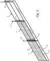
Figs. 1 and2 are perspective views of an embodiment of the temporary edge protection system according to the present invention, in an assembled state; -
Fig. 3 shows enlarged details of the edge protection system ofFig. 1 a. -
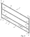
Figs. 4 to 6 are perspective views of different embodiments of barrier panels according to the invention; -
Figs. 7 to 9 are perspective partial views of different embodiments of bars according to the invention; -
Fig. 10 is a part view illustrating an embodiment of a bar coupling according to the invention; -
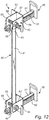
Figs. 11 and12 are perspective views of an embodiment of a panel holder according to this invention; -
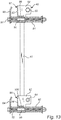
Fig. 13 is a partly cut-away view of a part of the panel holder ofFig. 11 ; -
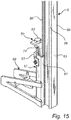
Figs. 14 and15 are perspective views of an embodiment of a post holder according to this invention; -
Fig. 16 is a cross-sectional view of the post holder inFig. 14 ; -
Fig. 17 is a perspective view of the panel holder inFig. 11 in a mounted state; and -
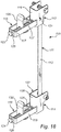
Fig. 18 is a perspective view of another embodiment of a panel holder according to this invention. - According to an embodiment of the temporary edge protection system 1, as shown in
Figs. 1 ,2 and3 it comprisesbarrier panels posts 5,panel holders 6 adjustably mountable on theposts 5, and postholders 7. Thepost holders 7 are arranged on abase 8, such as a floor, a concrete slab, or some other structure of a building. The edge protection system 1 is arranged close to the edge of the base, often several floors up, i.e. tens of meters above ground. There are different standards stating the requirements that the edge protection system must fulfill in order to be allowed for a particular use. For flat surfaces, and/or close to the ground, the requirements are of course lower than for sloping bases and/or high heights. Other parameters have an influence as well. The present edge protection system 1 is easily adaptable to the requirement of different standards due to its flexibility. For the users the weight of the system parts is an important factor, since they often assemble several hundreds of system parts during a working day. Therefore it is not optimal to provide one single embodiment which qualifies for the highest standard, since it becomes unnecessarily heavy for use in large volumes of lower standard applications. - According to the illustrated embodiment, the barrier panels 2-4, which are most cumbersome to handle, and the weight of which is particularly important, are made flexible to be easily adaptable to different standards, and applications. Furthermore, aluminum has been applied to a high extent for manufacturing different parts of the system. However even plastics has been found usable to some extent as will be explained below. The flexibility is illustrated with three example assemblies in
Figs. 4 to 6 . In order to obtain this flexibility, as shown in these figures as well as more detailed inFigs. 7-10 , the barrier panels 2-4 comprise at least three types of bars in slightly different combinations. - In other words, each barrier panel 2-4 comprises a set of aluminum bars including a
top bar 10, abottom bar 11, twoside bars 12, and anintermediate bar 13. According to one embodiment three different types of bars, i.e. aluminum profiles, have been employed, where the side bars 12 are of the same kind, and so are the top andbottom bars top bar 10 are connected, and at bottom ends 16 of the side bars 12 theends 17 of thebottom bar 11 are connected. Theintermediate bar 13 is attached to the side bars 12 between the top andbottom bars intermediate bar 13 is provided with atop connection groove 18 extending along its length and facing thetop bar 10, and abottom connection groove 19 extending along its length and facing thebottom bar 11, wherein eachside bar 12 is provided with severalbar attachment portions 22 spaced along the side bar. Thetop bar 10 is provided with a connection groove, or bottom connection groove, 20 facing theintermediate bar 13, and thebottom bar 11 has a connection groove, or top connection groove, 21, which faces theintermediate bar 13 as well. - More particularly, each
bar attachment portion 22 has a throughhole 23 extending laterally through theside bar 12, i.e. in parallel with thetop bar 10, and thebottom bar 11. For instance, at theintermediate bar 13, afastening member 24, here a screw, has been inserted through thehole 23 and received in as well as engaged with, here threaded into, one of theconnection grooves connection groove groove screw 24. The aluminum is soft enough to admit this, and additionally thescrew 24 can be designed to have a particular cutting thread. - The width of the
mouth cover elements barrier panel embodiment 2, thebarrier panel 2 has twointermediate bars 13, and one cover element, which is atoe board 28, arranged between a lower one of theintermediate bars 13 and thebottom bar 11 and engaged with thebottom connection groove 19 of theintermediate bar 13 and thetop connection groove 21 of thebottom bar 11. The openings between theintermediate bars 13 and between thetop bar 10 and an upper one of theintermediate bars 13 are uncovered. A secondbarrier panel embodiment 3 has the same parts as the first barrier panel embodiment, and additionally alower mesh section 29a arranged between theintermediate bars 13, and a similarupper mesh section 29b, arranged between the upper one of theintermediate bars 13 and thetop bar 10. A thirdbarrier panel embodiment 4 has oneintermediate bar 13, atoe board 28, and amesh section 30 arranged between thetop bar 10 and theintermediate bar 13. - Furthermore, according to embodiments of the barrier panel 2-4, each
side bar 12 is provided with at least onefriction element 35, e.g. twofriction elements 35 as shown inFig. 7 , on itsinner surface 36 facing the opposite side bar. Here theside bar 12 is provided with agroove 37 extending along the length thereof at saidinner surface 36, having a primary function of connecting mesh, plastic or other types of infill to the side of the frame. Thefriction elements 35 are provided as parallel ribs at either side of thegroove 37 and extend along the whole length of theside bar 12. The friction elements are arranged to engage with anend surface bar side bar 12. The height of thefriction elements 35 is low, they are merely like ribs slightly raised from the surface, i.e. like a surface pattern. Thefriction elements 35 raise the resistance against turning of thehorizontal bar fastening element 24, in particular a screw, is used. The use of asingle fastening element 24 is advantageous in that it is simpler to prepare the end of thehorizontal bar - As mentioned above, also plastic materials are employable, at least for the
toe board 28, which can be a plastic plate, and in particular a corrugated plastic plate. Properly oriented the corrugated plastic is strong enough already at thin and light dimensions, counted as weight per area unit. - In order to support the flexibility of the system while keeping the number of parts down, according to an embodiment of this invention adjustable panel supports 42, 43 are provided, as shown in
Figs. 11-13 . Thepanel holder 6 is capable of supporting many different kinds of edge protection members, such as the barrier panels 2-4, more particularly the aluminum bars 10, 12 thereof, therails 9, and any combination of them, from asingle bar rails 9, which is the thickest alternative of these edge protection members. Hence, the first embodiment of thepanel holder 6 comprises apost slider 40, movably arrangeable at apost 5 to extend in parallel with the post, and arranged to be locked in an arbitrary position along thepost 5. Thepost slider 40 comprises anelongated guide portion 41, and upper and lowerpost engagement portions bottom end portions guide portion 41. Theguide portion 41 is plate shaped and is arranged to be received in agroove 85, which extends along the length of thepost 5 at one side thereof. More particularly, thepost 5 is rectangular in cross-section and has alongitudinal flange 86 at each of its corners, seeFig. 17 . Theflanges 86 are arranged in pairs at opposite sides of thepost 5, and protrude from abase surface 87 of the post, thereby defining thegroove 85 between them. In other words thepost 5 has twoopposite grooves 85, at opposite sides of thepost 5. - Each one of the upper and lower
post engagement portions respective channel portion upper channel portion 55, it has three walls; abase wall 57, and first andsecond side walls element 60, which is engaged with theside walls post 5 between them, to thereby lock thepanel holder 6 in the chosen position. Like in this embodiment the lockingelement 60 can simply be a screw extending through holes of the first andsecond side walls nut 66 attached to thesecond wall 59 in alignment with the hole. Thelower channel portion 56 is similar to theupper channel portion 55, having abase wall 61 andside walls side walls general connection element 64 just closing the opening between theside walls panel holder 6 from moving unintentionally. - Two panel supports 47, 48 are connected with the
post slider 40 at a distance from each other. More particularly, the panel supports 47, 48 are connected with the upper and lowerpost engagement portions panel support adjustable clamping element adjustment element element post slider 40. Each clampingelement elongated support portion vertical tongue portion support portion support portion post engagement portion support portion first wall channel portion post engagement portions panel clamping surface tongue portion element adjustment element element post engagement portion - In this embodiment, the adjustment element of each
panel support support portion sleeve post engagement portion post engagement portion angle bar first side wall angle bar clamp surface base wall bottom plate portion clamp surface sleeve 95 is attached to the outside of thefirst wall support portion first side wall sleeve support portion screw support portion support portion screw element support portion sleeve tongue portion clamp surface post engagement portion - Thus, when mounting the temporary edge protection, the
panel holder 6 is mounted on apost 5 by slipping thepost engagement portions post 5 from one end thereof, such that theguide element 41 is received in a correspondinggroove 85 extending along thepost 5. Then thepanel holder 6 is moved to the desired position along thepost 5, and the lockingelement 60 is tightened. The barrier panel(s) and/or rail(s) are placed on the panel supports 47, 48, i.e. they are received in the space between the clampingelements adjustment elements elements post slider 40. - According to another embodiment of the
panel holder 110, as shown inFig. 18 , similar to the above embodiment, it comprises apost slider 111, having anelongated guide portion 112 and upper and lowerport engagement portions post engagement portions panel holder bracket base wall channel portion post engagement portion bracket adjustment element bracket screw bracket portion opposite cross wall base wall post slider 112, and having a screw head and a fixed nut at its respective ends. The clampingelement screw bracket screw element base wall - Referring to
Figs. 14 to 16 , thepost holder 7 comprises an elongated verticalpost retaining portion 67, and abase support portion 68 protruding horizontally from thepost retaining portion 67, and arranged to rest on thebase 8. Thepost retaining portion 67 is generally channel-shaped and has abottom wall 80, andopposite side walls 81 raising from thebottom wall 80, theside walls 81 having a J-shaped cross-section. Thus, when thepost 5 is in a mounted state, the edges of theside walls 81 are engaged with twoflanges 86, a portion of thepost 5 thus extending through thepost retaining portion 67. Thepost 5 has asnap lock device 71, which comprises a springbiased locking pin 72, which is received in arecess 73 of the post holder when thepost 5 is in the mounted state. This kind of post shape and connection of thepost holder 7 and thepost 5 is advantageous in that the opposite side of the post, having a similar groove shape, is free to use in the full length of the post for connecting other parts. - Furthermore, the
post holder 7 comprises apost tightening assembly 70. Thepost tightening assembly 70 comprises amovable element 74 and a fixedelement 75, wherein themovable element 74 is arranged to exert a tightening force on asurface 76 of thepost 5 when moved to a tightening position. Thesurface 76 extends between theflanges 86 that the side wall edges of thepost holder 7 are engaged with. It should be noted that thispost surface 76 is typically opposite to the above mentionedpost surface 63 facing thepanel holder 6. That is, thepost holder 7 and thepanel holder 6 are mounted on opposite sides of thepost 5. Themovable element 74 constitutes a filling piece between the fixedelement 75 and thesurface 76 of thepost 5. The fixedelement 75 is arranged within thepost retaining portion 67. The fixedelement 75 comprises aguide surface 84, which is inclined relative to thesurface 76 of the post, and relative to thebottom wall 80. Themovable element 74 is vertically adjusted by means of a tighteningscrew 82, which is arranged in a fixednut element 83, and which is loosely connected with themovable element 74. The nut element is arranged at an outside of thepost retaining portion 67, and themovable element 74, constituted by a bent plate, extends into the retainingportion 67 from an upper end thereof, and abuts against theguide surface 84 of the fixedelement 75. When tightening the tighteningscrew 82, themovable element 74 is forced downwards between theguide surface 84 and thesurface 76 of thepost 5 like a wedge. Thereby thepost 5, and more particularly theflanges 86 thereof, is pushed against the edges of theside walls 81 of thepost retaining portion 67. - The post tightening assembly is eqully applicable for other post shapes, such as a conventional tube shaped post, rectangular or circular, which is received in a slightly wider, tube portion of the post holder. That is, the tube portion of the post holder can be provided with a similar arrangement of fixed and movable parts and inclined surface(s), as understood by the person skilled in the art.
- While the invention has been illustrated and described in detail in the drawings and foregoing description, such illustration and description are to be considered illustrative or exemplary and not restrictive; the invention is not limited to the disclosed embodiments.
- Other variations to the disclosed embodiments can be understood and effected by those skilled in the art in practicing the claimed invention, without departing from the scope as defined by the appended claims. In the claims, the word "comprising" does not exclude other elements or steps, and the indefinite article "a" or "an" does not exclude a plurality. The mere fact that certain measures are recited in mutually different dependent claims does not indicate that a combination of these measured cannot be used to advantage. Any reference signs in the claims should not be construed as limiting the scope.
Claims (13)
- A barrier panel for a temporary edge protection system, the barrier panel (2-4) comprising a set of aluminum bars including a top bar (10), a bottom bar (11), two side bars (12), and an intermediate bar (13), wherein the side bars are connected at their ends (14, 16) with first respectively second ends (15, 17) of the top and bottom bars to form a rectangular section, wherein the intermediate bar is attached to the side bars between the top and bottom bars, wherein the intermediate bar is provided with a top connection groove (18) extending along its length and facing the top bar, and a bottom connection groove (19) extending along its length and facing the bottom bar, characterized in that:the top and bottom connection grooves are connectable with a material covering the openings between the bars by means of a complementary connection element, wherein each side bar is provided with several bar attachment portions (22) spaced along the side bar, the barrier panel further comprising fastening members (24), wherein a first fastening member is engaged with one of the side bars at one of its bar attachment portions, and is received in one of the connection grooves (18, 19) of the intermediate bar at one end thereof and engaged with that connection groove, wherein a second fastening member is engaged with the other side bar at one of its bar attachment portions, and is received in one of the connection grooves of the intermediate bar at the other end thereof and engaged with that connection groove, and wherein each side bar is provided with a friction element (35) on its surface (36) facing the opposite side bar, said friction element being arranged to engage with an end surface (38, 39) of each bar which is connected with the side bar.
- The barrier panel according to claim 1, wherein each bar attachment portion (22) comprises a through hole (23) extending in parallel with the top bar (10).
- The barrier panel according to claim 1 or 2, wherein the width of a mouth (25) of each connection groove (18, 19) is smaller than the largest width of the connection groove.
- The barrier panel according to any one of the preceding claims, said friction element (35) comprising a rib (35) extending along the length of the side bar (12).
- The barrier panel according to any one of the preceding claims, further comprising a toe board (28) arranged between an intermediate bar (13) and the bottom bar (11) and engaged with a bottom connection groove (19) of the intermediate bar and a top connection groove (21) of the bottom bar.
- The barrier panel according to claim 5, wherein the toe board (28) is a plastic plate.
- The barrier panel according to claim 6, wherein the toe board (28) is made of corrugated plastic.
- A temporary edge protection system comprising a barrier panel according to any one of the preceding claims, further comprising a post holder (7) being arranged to be provided on a base (8), and to receive a post (5), wherein the post holder comprises a post tightening assembly (70).
- The temporary edge protection system according to claim 8, wherein the post tightening assembly (70) comprises a movable element (74) and a fixed element (75), wherein the movable element is arranged to exert a tightening force on a surface (76) of the post when moved to a tightening position, wherein the movable element constitutes a filling piece between the fixed element and the surface of the post, and wherein at least one of the movable element and the fixed element comprises a guide surface (84), which is inclined relative to the surface of the post.
- A temporary edge protection system comprising a barrier panel according to any one of claims 1 to 7, further comprising a panel holder (6, 110) adjustably mountable on a post, wherein the panel holder comprises an elongate post slider (40, 111), movably arrangeable at the post to extend in parallel with the post, and two panel supports (47, 48, 115, 116), attached to the post slider at a distance from each other, each panel support comprising an adjustable clamping element (49, 50, 129, 130), and an adjusting element (51, 52, 123, 124) arranged to change the distance between the clamping element and the post slider.
- The temporary edge protection system according to claim 10, each panel support (47, 48, 115, 116) comprising a horizontal elongated support portion (91, 92, 117, 118), on which edge protection members (2-4, 9) are to rest, and a vertical tongue portion (93, 94, 129, 130) arranged to clamp the edge protection members (2-4, 9) against a clamp surface (53, 54, 119, 120) of the post slider (40, 111).
- The temporary edge protection system according to claim 10 or 11, wherein the post slider (40, 111) comprises an elongated guide portion (41, 112), and upper and lower post engagement portions (43, 44, 121, 122) respectively arranged at top and bottom end portions (45, 46) of the guide portion (41, 112), wherein the support portion (91, 92) is comprised in the clamping element (49, 50), wherein the tongue portion (93, 94) is attached to the support portion, and wherein the support portion is longitudinally displaceably connected with the post engagement portion (43, 44).
- The temporary edge protection system according to any one of claims 10 to 12, further comprising a post holder (7) arranged to be provided on a base (8), wherein the post holder comprises a post tightening assembly (70).
Priority Applications (4)
| Application Number | Priority Date | Filing Date | Title |
|---|---|---|---|
| LTEP13192178.5T LT2871303T (en) | 2013-11-08 | 2013-11-08 | A temporary edge protection system |
| PL13192178T PL2871303T3 (en) | 2013-11-08 | 2013-11-08 | A temporary edge protection system |
| EP13192178.5A EP2871303B1 (en) | 2013-11-08 | 2013-11-08 | A temporary edge protection system |
| DK13192178.5T DK2871303T3 (en) | 2013-11-08 | 2013-11-08 | Temporary edge protection system |
Applications Claiming Priority (1)
| Application Number | Priority Date | Filing Date | Title |
|---|---|---|---|
| EP13192178.5A EP2871303B1 (en) | 2013-11-08 | 2013-11-08 | A temporary edge protection system |
Publications (2)
| Publication Number | Publication Date |
|---|---|
| EP2871303A1 EP2871303A1 (en) | 2015-05-13 |
| EP2871303B1 true EP2871303B1 (en) | 2017-02-01 |
Family
ID=49554105
Family Applications (1)
| Application Number | Title | Priority Date | Filing Date |
|---|---|---|---|
| EP13192178.5A Active EP2871303B1 (en) | 2013-11-08 | 2013-11-08 | A temporary edge protection system |
Country Status (4)
| Country | Link |
|---|---|
| EP (1) | EP2871303B1 (en) |
| DK (1) | DK2871303T3 (en) |
| LT (1) | LT2871303T (en) |
| PL (1) | PL2871303T3 (en) |
Cited By (1)
| Publication number | Priority date | Publication date | Assignee | Title |
|---|---|---|---|---|
| NL1044380B1 (en) * | 2022-08-16 | 2024-02-21 | B Struijk Holding B V | MultySafe safety system (MultySafe) |
Families Citing this family (5)
| Publication number | Priority date | Publication date | Assignee | Title |
|---|---|---|---|---|
| GB2530478B (en) * | 2014-08-04 | 2017-10-04 | Sayfa Systems Uk Ltd | A safety barrier, a kit of parts for constructing a safety barrier, a method of constructing a safety barrier and an elongate member |
| GB201601315D0 (en) * | 2016-01-25 | 2016-03-09 | Brand Energy & Infrastructure Services Uk Ltd | A safety screen |
| CN111236609A (en) * | 2020-01-16 | 2020-06-05 | 中铁二局集团有限公司 | Super high-rise climbing frame operation layer platform protection system |
| CN112576095B (en) * | 2020-11-25 | 2025-04-11 | 国网宁夏电力有限公司中卫供电公司 | Safety fence that is easy to install |
| CN116677257B (en) * | 2023-08-04 | 2023-10-20 | 上海建工集团股份有限公司 | Prefabricated enclosure system convenient to install and detach and use method thereof |
Citations (3)
| Publication number | Priority date | Publication date | Assignee | Title |
|---|---|---|---|---|
| US3037593A (en) * | 1959-06-25 | 1962-06-05 | Clifford L Webster | Partition construction |
| DE4210998A1 (en) * | 1991-04-03 | 1992-10-22 | Papst Hans Dieter | Protective grid with fixed frame parts - has holder element formed as bar, with longitudinal groove in which side edge of surface pattern is accommodated |
| US20100025648A1 (en) * | 2008-08-01 | 2010-02-04 | Walpole Herbert L | Pre-manufactured fence system |
Family Cites Families (5)
| Publication number | Priority date | Publication date | Assignee | Title |
|---|---|---|---|---|
| US3851858A (en) * | 1973-10-29 | 1974-12-03 | Sybron Corp | Toeboard |
| US20100327246A1 (en) * | 2009-06-24 | 2010-12-30 | Mckell James W | Modular fence system and method |
| DE102009037977A1 (en) * | 2009-08-13 | 2012-04-12 | Siegmar Baum | Shut-off element e.g. building fence, for use with pivoting device, has separating element whose adapted molding element is engaged with groove-like receiver, where separating element is fixed at frame of pipe elements |
| DE102009044483A1 (en) * | 2009-11-10 | 2011-05-12 | Friedr. Ischebeck Gmbh | Side guard and side protection system |
| US20130240817A1 (en) * | 2012-03-16 | 2013-09-19 | Adjustable Forms, Inc. | Guardrail System |
-
2013
- 2013-11-08 PL PL13192178T patent/PL2871303T3/en unknown
- 2013-11-08 EP EP13192178.5A patent/EP2871303B1/en active Active
- 2013-11-08 LT LTEP13192178.5T patent/LT2871303T/en unknown
- 2013-11-08 DK DK13192178.5T patent/DK2871303T3/en active
Patent Citations (3)
| Publication number | Priority date | Publication date | Assignee | Title |
|---|---|---|---|---|
| US3037593A (en) * | 1959-06-25 | 1962-06-05 | Clifford L Webster | Partition construction |
| DE4210998A1 (en) * | 1991-04-03 | 1992-10-22 | Papst Hans Dieter | Protective grid with fixed frame parts - has holder element formed as bar, with longitudinal groove in which side edge of surface pattern is accommodated |
| US20100025648A1 (en) * | 2008-08-01 | 2010-02-04 | Walpole Herbert L | Pre-manufactured fence system |
Cited By (1)
| Publication number | Priority date | Publication date | Assignee | Title |
|---|---|---|---|---|
| NL1044380B1 (en) * | 2022-08-16 | 2024-02-21 | B Struijk Holding B V | MultySafe safety system (MultySafe) |
Also Published As
| Publication number | Publication date |
|---|---|
| EP2871303A1 (en) | 2015-05-13 |
| PL2871303T3 (en) | 2017-08-31 |
| LT2871303T (en) | 2017-04-10 |
| DK2871303T3 (en) | 2017-05-08 |
Similar Documents
| Publication | Publication Date | Title |
|---|---|---|
| DK2871303T3 (en) | Temporary edge protection system | |
| US9249577B2 (en) | Cable railing | |
| CA2878342C (en) | Railing system and tensioned posts used therein | |
| US20250052088A1 (en) | Vertical cable rail barrier | |
| EP2238871B1 (en) | System for the production of a multifunction wall which can be mounted on a wall, in particular a room divider, and method for producing and mounting a multifunction wall | |
| US20150300041A1 (en) | Railing assembly with interference fit-based coupling | |
| EP2707561B1 (en) | Safety barricade system | |
| US9228372B2 (en) | Fence rail and bracket system | |
| US20120018692A1 (en) | Fence rail support system | |
| GB2512150A (en) | Support for rigid panel | |
| US20230212875A1 (en) | Modular fencing system | |
| EP2871302B1 (en) | Mounting arrangement for a temporary edge protection system | |
| KR101582539B1 (en) | fixing apparatus of pillar | |
| AU2009100361A4 (en) | Modular panel construction | |
| EP1712711B1 (en) | Fencing system | |
| CA2638297A1 (en) | Adjustable fencing system | |
| CN108495971A (en) | Fences with concealed fasteners and noise reduction | |
| US20200378148A1 (en) | System And Method For Constructing A Railing | |
| CA2621690A1 (en) | Storage kit | |
| GB2530478A (en) | A safety barrier, a kit of parts for constructing a safety barrier, a method of constructing a safety barrier and an elongate member | |
| KR20140135574A (en) | A fixing member for fixing a glass | |
| JP2004036298A (en) | Vane of blindfold fence and structure of blindfold fence | |
| KR20140004352U (en) | Connecting structure of cantilever beam and horizontal beam for shelter | |
| CA2376692A1 (en) | Railing apparatus with variable positionable rails | |
| HK1196650B (en) | Safety barricade system |
Legal Events
| Date | Code | Title | Description |
|---|---|---|---|
| PUAI | Public reference made under article 153(3) epc to a published international application that has entered the european phase |
Free format text: ORIGINAL CODE: 0009012 |
|
| 17P | Request for examination filed |
Effective date: 20131108 |
|
| AK | Designated contracting states |
Kind code of ref document: A1 Designated state(s): AL AT BE BG CH CY CZ DE DK EE ES FI FR GB GR HR HU IE IS IT LI LT LU LV MC MK MT NL NO PL PT RO RS SE SI SK SM TR |
|
| AX | Request for extension of the european patent |
Extension state: BA ME |
|
| R17P | Request for examination filed (corrected) |
Effective date: 20151113 |
|
| RBV | Designated contracting states (corrected) |
Designated state(s): AL AT BE BG CH CY CZ DE DK EE ES FI FR GB GR HR HU IE IS IT LI LT LU LV MC MK MT NL NO PL PT RO RS SE SI SK SM TR |
|
| 17Q | First examination report despatched |
Effective date: 20151221 |
|
| GRAP | Despatch of communication of intention to grant a patent |
Free format text: ORIGINAL CODE: EPIDOSNIGR1 |
|
| INTG | Intention to grant announced |
Effective date: 20160901 |
|
| GRAS | Grant fee paid |
Free format text: ORIGINAL CODE: EPIDOSNIGR3 |
|
| GRAJ | Information related to disapproval of communication of intention to grant by the applicant or resumption of examination proceedings by the epo deleted |
Free format text: ORIGINAL CODE: EPIDOSDIGR1 |
|
| GRAL | Information related to payment of fee for publishing/printing deleted |
Free format text: ORIGINAL CODE: EPIDOSDIGR3 |
|
| GRAP | Despatch of communication of intention to grant a patent |
Free format text: ORIGINAL CODE: EPIDOSNIGR1 |
|
| INTC | Intention to grant announced (deleted) | ||
| INTG | Intention to grant announced |
Effective date: 20161130 |
|
| GRAA | (expected) grant |
Free format text: ORIGINAL CODE: 0009210 |
|
| AK | Designated contracting states |
Kind code of ref document: B1 Designated state(s): AL AT BE BG CH CY CZ DE DK EE ES FI FR GB GR HR HU IE IS IT LI LT LU LV MC MK MT NL NO PL PT RO RS SE SI SK SM TR |
|
| REG | Reference to a national code |
Ref country code: GB Ref legal event code: FG4D |
|
| REG | Reference to a national code |
Ref country code: CH Ref legal event code: EP Ref country code: AT Ref legal event code: REF Ref document number: 865747 Country of ref document: AT Kind code of ref document: T Effective date: 20170215 |
|
| REG | Reference to a national code |
Ref country code: IE Ref legal event code: FG4D |
|
| REG | Reference to a national code |
Ref country code: DE Ref legal event code: R096 Ref document number: 602013016949 Country of ref document: DE |
|
| REG | Reference to a national code |
Ref country code: DK Ref legal event code: T3 Effective date: 20170502 |
|
| REG | Reference to a national code |
Ref country code: SE Ref legal event code: TRGR |
|
| REG | Reference to a national code |
Ref country code: EE Ref legal event code: FG4A Ref document number: E013558 Country of ref document: EE Effective date: 20170314 |
|
| REG | Reference to a national code |
Ref country code: NL Ref legal event code: MP Effective date: 20170201 |
|
| REG | Reference to a national code |
Ref country code: NO Ref legal event code: T2 Effective date: 20170201 |
|
| REG | Reference to a national code |
Ref country code: AT Ref legal event code: MK05 Ref document number: 865747 Country of ref document: AT Kind code of ref document: T Effective date: 20170201 |
|
| PG25 | Lapsed in a contracting state [announced via postgrant information from national office to epo] |
Ref country code: IS Free format text: LAPSE BECAUSE OF FAILURE TO SUBMIT A TRANSLATION OF THE DESCRIPTION OR TO PAY THE FEE WITHIN THE PRESCRIBED TIME-LIMIT Effective date: 20170601 Ref country code: GR Free format text: LAPSE BECAUSE OF FAILURE TO SUBMIT A TRANSLATION OF THE DESCRIPTION OR TO PAY THE FEE WITHIN THE PRESCRIBED TIME-LIMIT Effective date: 20170502 Ref country code: HR Free format text: LAPSE BECAUSE OF FAILURE TO SUBMIT A TRANSLATION OF THE DESCRIPTION OR TO PAY THE FEE WITHIN THE PRESCRIBED TIME-LIMIT Effective date: 20170201 |
|
| PG25 | Lapsed in a contracting state [announced via postgrant information from national office to epo] |
Ref country code: BG Free format text: LAPSE BECAUSE OF FAILURE TO SUBMIT A TRANSLATION OF THE DESCRIPTION OR TO PAY THE FEE WITHIN THE PRESCRIBED TIME-LIMIT Effective date: 20170501 Ref country code: RS Free format text: LAPSE BECAUSE OF FAILURE TO SUBMIT A TRANSLATION OF THE DESCRIPTION OR TO PAY THE FEE WITHIN THE PRESCRIBED TIME-LIMIT Effective date: 20170201 Ref country code: ES Free format text: LAPSE BECAUSE OF FAILURE TO SUBMIT A TRANSLATION OF THE DESCRIPTION OR TO PAY THE FEE WITHIN THE PRESCRIBED TIME-LIMIT Effective date: 20170201 Ref country code: PT Free format text: LAPSE BECAUSE OF FAILURE TO SUBMIT A TRANSLATION OF THE DESCRIPTION OR TO PAY THE FEE WITHIN THE PRESCRIBED TIME-LIMIT Effective date: 20170601 Ref country code: AT Free format text: LAPSE BECAUSE OF FAILURE TO SUBMIT A TRANSLATION OF THE DESCRIPTION OR TO PAY THE FEE WITHIN THE PRESCRIBED TIME-LIMIT Effective date: 20170201 Ref country code: NL Free format text: LAPSE BECAUSE OF FAILURE TO SUBMIT A TRANSLATION OF THE DESCRIPTION OR TO PAY THE FEE WITHIN THE PRESCRIBED TIME-LIMIT Effective date: 20170201 |
|
| REG | Reference to a national code |
Ref country code: SK Ref legal event code: T3 Ref document number: E 23798 Country of ref document: SK |
|
| PG25 | Lapsed in a contracting state [announced via postgrant information from national office to epo] |
Ref country code: IT Free format text: LAPSE BECAUSE OF FAILURE TO SUBMIT A TRANSLATION OF THE DESCRIPTION OR TO PAY THE FEE WITHIN THE PRESCRIBED TIME-LIMIT Effective date: 20170201 Ref country code: RO Free format text: LAPSE BECAUSE OF FAILURE TO SUBMIT A TRANSLATION OF THE DESCRIPTION OR TO PAY THE FEE WITHIN THE PRESCRIBED TIME-LIMIT Effective date: 20170201 |
|
| REG | Reference to a national code |
Ref country code: DE Ref legal event code: R097 Ref document number: 602013016949 Country of ref document: DE |
|
| REG | Reference to a national code |
Ref country code: FR Ref legal event code: PLFP Year of fee payment: 5 |
|
| PG25 | Lapsed in a contracting state [announced via postgrant information from national office to epo] |
Ref country code: SM Free format text: LAPSE BECAUSE OF FAILURE TO SUBMIT A TRANSLATION OF THE DESCRIPTION OR TO PAY THE FEE WITHIN THE PRESCRIBED TIME-LIMIT Effective date: 20170201 |
|
| PLBE | No opposition filed within time limit |
Free format text: ORIGINAL CODE: 0009261 |
|
| STAA | Information on the status of an ep patent application or granted ep patent |
Free format text: STATUS: NO OPPOSITION FILED WITHIN TIME LIMIT |
|
| 26N | No opposition filed |
Effective date: 20171103 |
|
| PG25 | Lapsed in a contracting state [announced via postgrant information from national office to epo] |
Ref country code: SI Free format text: LAPSE BECAUSE OF FAILURE TO SUBMIT A TRANSLATION OF THE DESCRIPTION OR TO PAY THE FEE WITHIN THE PRESCRIBED TIME-LIMIT Effective date: 20170201 |
|
| PG25 | Lapsed in a contracting state [announced via postgrant information from national office to epo] |
Ref country code: MC Free format text: LAPSE BECAUSE OF FAILURE TO SUBMIT A TRANSLATION OF THE DESCRIPTION OR TO PAY THE FEE WITHIN THE PRESCRIBED TIME-LIMIT Effective date: 20170201 |
|
| PG25 | Lapsed in a contracting state [announced via postgrant information from national office to epo] |
Ref country code: LI Free format text: LAPSE BECAUSE OF NON-PAYMENT OF DUE FEES Effective date: 20171130 Ref country code: CH Free format text: LAPSE BECAUSE OF NON-PAYMENT OF DUE FEES Effective date: 20171130 |
|
| PG25 | Lapsed in a contracting state [announced via postgrant information from national office to epo] |
Ref country code: LU Free format text: LAPSE BECAUSE OF NON-PAYMENT OF DUE FEES Effective date: 20171108 |
|
| REG | Reference to a national code |
Ref country code: BE Ref legal event code: MM Effective date: 20171130 |
|
| REG | Reference to a national code |
Ref country code: IE Ref legal event code: MM4A |
|
| PG25 | Lapsed in a contracting state [announced via postgrant information from national office to epo] |
Ref country code: MT Free format text: LAPSE BECAUSE OF NON-PAYMENT OF DUE FEES Effective date: 20171108 |
|
| REG | Reference to a national code |
Ref country code: FR Ref legal event code: PLFP Year of fee payment: 6 |
|
| PG25 | Lapsed in a contracting state [announced via postgrant information from national office to epo] |
Ref country code: IE Free format text: LAPSE BECAUSE OF NON-PAYMENT OF DUE FEES Effective date: 20171108 |
|
| PG25 | Lapsed in a contracting state [announced via postgrant information from national office to epo] |
Ref country code: BE Free format text: LAPSE BECAUSE OF NON-PAYMENT OF DUE FEES Effective date: 20171130 |
|
| PG25 | Lapsed in a contracting state [announced via postgrant information from national office to epo] |
Ref country code: HU Free format text: LAPSE BECAUSE OF FAILURE TO SUBMIT A TRANSLATION OF THE DESCRIPTION OR TO PAY THE FEE WITHIN THE PRESCRIBED TIME-LIMIT; INVALID AB INITIO Effective date: 20131108 |
|
| PG25 | Lapsed in a contracting state [announced via postgrant information from national office to epo] |
Ref country code: CY Free format text: LAPSE BECAUSE OF FAILURE TO SUBMIT A TRANSLATION OF THE DESCRIPTION OR TO PAY THE FEE WITHIN THE PRESCRIBED TIME-LIMIT Effective date: 20170201 |
|
| PG25 | Lapsed in a contracting state [announced via postgrant information from national office to epo] |
Ref country code: MK Free format text: LAPSE BECAUSE OF FAILURE TO SUBMIT A TRANSLATION OF THE DESCRIPTION OR TO PAY THE FEE WITHIN THE PRESCRIBED TIME-LIMIT Effective date: 20170201 |
|
| PG25 | Lapsed in a contracting state [announced via postgrant information from national office to epo] |
Ref country code: TR Free format text: LAPSE BECAUSE OF FAILURE TO SUBMIT A TRANSLATION OF THE DESCRIPTION OR TO PAY THE FEE WITHIN THE PRESCRIBED TIME-LIMIT Effective date: 20170201 |
|
| PG25 | Lapsed in a contracting state [announced via postgrant information from national office to epo] |
Ref country code: AL Free format text: LAPSE BECAUSE OF FAILURE TO SUBMIT A TRANSLATION OF THE DESCRIPTION OR TO PAY THE FEE WITHIN THE PRESCRIBED TIME-LIMIT Effective date: 20170201 |
|
| PGFP | Annual fee paid to national office [announced via postgrant information from national office to epo] |
Ref country code: DE Payment date: 20251016 Year of fee payment: 13 |
|
| PGFP | Annual fee paid to national office [announced via postgrant information from national office to epo] |
Ref country code: LT Payment date: 20251027 Year of fee payment: 13 Ref country code: GB Payment date: 20251016 Year of fee payment: 13 |
|
| PGFP | Annual fee paid to national office [announced via postgrant information from national office to epo] |
Ref country code: NO Payment date: 20251021 Year of fee payment: 13 |
|
| PGFP | Annual fee paid to national office [announced via postgrant information from national office to epo] |
Ref country code: FI Payment date: 20251014 Year of fee payment: 13 Ref country code: DK Payment date: 20251015 Year of fee payment: 13 |
|
| PGFP | Annual fee paid to national office [announced via postgrant information from national office to epo] |
Ref country code: FR Payment date: 20251016 Year of fee payment: 13 |
|
| PGFP | Annual fee paid to national office [announced via postgrant information from national office to epo] |
Ref country code: SE Payment date: 20251015 Year of fee payment: 13 |
|
| PGFP | Annual fee paid to national office [announced via postgrant information from national office to epo] |
Ref country code: CZ Payment date: 20251105 Year of fee payment: 13 |
|
| PGFP | Annual fee paid to national office [announced via postgrant information from national office to epo] |
Ref country code: LV Payment date: 20251116 Year of fee payment: 13 |
|
| PGFP | Annual fee paid to national office [announced via postgrant information from national office to epo] |
Ref country code: PL Payment date: 20251002 Year of fee payment: 13 |
|
| PGFP | Annual fee paid to national office [announced via postgrant information from national office to epo] |
Ref country code: EE Payment date: 20251120 Year of fee payment: 13 |
|
| PGFP | Annual fee paid to national office [announced via postgrant information from national office to epo] |
Ref country code: SK Payment date: 20251104 Year of fee payment: 13 |