EP2871295B1 - Sanitary cleansing device - Google Patents
Sanitary cleansing device Download PDFInfo
- Publication number
- EP2871295B1 EP2871295B1 EP13813147.9A EP13813147A EP2871295B1 EP 2871295 B1 EP2871295 B1 EP 2871295B1 EP 13813147 A EP13813147 A EP 13813147A EP 2871295 B1 EP2871295 B1 EP 2871295B1
- Authority
- EP
- European Patent Office
- Prior art keywords
- cleansing
- water
- water level
- nozzle
- tank
- Prior art date
- Legal status (The legal status is an assumption and is not a legal conclusion. Google has not performed a legal analysis and makes no representation as to the accuracy of the status listed.)
- Active
Links
Images


Classifications
-
- E—FIXED CONSTRUCTIONS
- E03—WATER SUPPLY; SEWERAGE
- E03D—WATER-CLOSETS OR URINALS WITH FLUSHING DEVICES; FLUSHING VALVES THEREFOR
- E03D9/00—Sanitary or other accessories for lavatories ; Devices for cleaning or disinfecting the toilet room or the toilet bowl; Devices for eliminating smells
- E03D9/08—Devices in the bowl producing upwardly-directed sprays; Modifications of the bowl for use with such devices ; Bidets; Combinations of bowls with urinals or bidets; Hot-air or other devices mounted in or on the bowl, urinal or bidet for cleaning or disinfecting
Definitions
- the present invention relates to flow rate control of cleansing water in a sanitary cleansing device.
- a sanitary cleansing device described in PTL 1 includes a flow sensor at an upstream side of a heat exchanger for heating cleansing water.
- the flow sensor is configured by a swirl chamber in which cleansing water flows in a substantially U-shape, a rotor having a swirler, a photo interrupter, and the like. Then, the photo interrupter detects light interruption by the swirler rotated by the cleansing water that flows in the swirl chamber of the flow sensor, and detects a flow rate. Consequently, it is possible to detect the flow rate of the cleansing water with high detection precision, and to heat the cleansing water to a proper temperature with a heater of the heat exchanger.
- a sanitary cleansing device of the present invention includes: a cleansing nozzle configured to discharge cleansing water; and a cleansing water flow passage configured to allow the cleansing water from a supply source to flow toward the cleansing nozzle.
- the cleansing water flow passage has: a displacement pump configured to control a flow rate of the cleansing water discharged from the cleansing nozzle; an atmosphere open part disposed at an upstream side of the displacement pump, configured to open a part of the cleansing water flow passage to atmosphere, and having a tank for storing the cleansing water, and a water level sensor for detecting a water level in the tank to output a signal; a solenoid valve configured to pass and block the cleansing water supplied from the supply source to the atmosphere open part; and a controller configured to control the displacement pump and the solenoid valve. Furthermore, the controller calculates flow rate of the cleansing water supplied per unit time from the supply source based on the signal of the water level sensor, and corrects control of the displacement pump.
- the displacement pump is disposed downstream of the atmosphere open part, so that a number of rotations of the displacement pump is controlled with no influence of supply pressure of the water supply source, and the flow rate of the cleansing water discharged from the cleansing nozzle is controlled.
- the water level sensor measures a flow rate of cleansing water that has actually passed, and feeds back the measured flow rate to the controller, so that the control of the displacement pump is corrected. Consequently, the flow rate detected by the water level sensor is corrected, and the flow rate of the cleansing water jetted from the displacement pump can be controlled with no influence of variations in components, aged deterioration, or the like.
- FIG. 1 a sanitary cleansing device according to a first exemplary embodiment of the present invention, and a toilet device with the same will be described with reference to FIG. 1 .
- FIG. 1 is a perspective view of the toilet device mounted with the sanitary cleansing device according to the first exemplary embodiment of the present invention.
- Toilet device 1000 is installed in a toilet room.
- toilet device 1000 of this exemplary embodiment includes at least sanitary cleansing device 100, toilet bowl 700, room entry detection sensor 600, and the like, and is mounted with sanitary cleansing device 100 on toilet bowl 700.
- Sanitary cleansing device 100 is configured by main body 200, remote controller 300, toilet seat 400, lid 500, and the like.
- Main body part 200 incorporates a cleansing water supply mechanism (see FIG. 3 ) that is controlled by sitting sensor 610 and controller 4 provided on a front upper part, and is openably mounted with toilet seat 400 and lid 500.
- Sitting sensor 610 is configured by, for example, a reflective infrared sensor, and detects an infrared ray reflected from a human body, to detect whether or not a user is present on toilet seat 400.
- the cleansing water supply mechanism incorporated in main body 200 has one end connected to toilet bowl nozzle 40 provided on a front lower part of main body 200 and the other end connected to a tap water piping.
- FIG. 1 shows a state where toilet bowl nozzle 40 protrudes inside toilet bowl 700. Consequently, the cleansing water supply mechanism supplies cleansing water supplied from the tap water piping to toilet bowl nozzle 40.
- the supplied cleansing water is jetted from toilet bowl nozzle 40 into a wide range of an inner surface of toilet bowl 700.
- the cleansing water is jetted from toilet bowl nozzle 40 to a rear surface side of the inner surface of toilet bowl 700.
- a cleansing water supply mechanism incorporated in main body 200 is connected to nozzle part 20 configured by buttock nozzle 1 that serves as a private part cleansing nozzle, bidet nozzle 2 that serves as a bidet cleansing nozzle, nozzle cleansing nozzle 3, toilet bowl nozzle 40, and the like, which configure a cleansing nozzle (see FIG. 3 ). Consequently, the cleansing water supply mechanism supplies cleansing water supplied from a tap water piping, to nozzle part 20. Then, the supplied cleansing water is jetted from buttock nozzle 1, bidet nozzle 2, or the like to a private part of a user. Additionally, cleansing water supplied to nozzle cleansing nozzle 3 of nozzle part 20 is jet to nozzle part 20 such as buttock nozzle 1 and bidet nozzle 2, thereby cleansing the nozzles.
- Operation part such as remote controller 300 has a plurality of switches for selecting cleansing modes of cleansing a plurality of cleansing nozzles, and is mounted on, for example, a place where the user sitting on toilet seat 400 can operate.
- Room entry detection sensor 600 is configured by, for example, a reflective infrared sensor, and is mounted on an entrance of the toilet room or the like. In a case where room entry detection sensor 600 detects an infrared ray reflected from the human body, room entry detection sensor 600 detects that the user entered the toilet room.
- Controller 4 (see FIG. 3 ) of main body 200 controls operation of respective parts of sanitary cleansing device 100 based on signals transmitted from remote controller 300, room entry detection sensor 600, and sitting sensor 610.
- remote controller 300 of sanitary cleansing device 100 will be described with reference to FIG. 2 .
- FIG. 2 is a front view of the remote controller of the sanitary cleansing device according to this exemplary embodiment.
- remote controller 300 includes wide cleansing switch 305, rhythm cleansing switch 306, water force setting switches 307 and 308, move cleansing switch 309, and cleansing position setting switches 310 and 311 which are provided on an upper part of controller main body 301, and stop switch 302 for instructing cleansing operation, buttock switch 303, and bidet switch 304 which are provided on a lower part of controller main body 301.
- Controller 4 controls operation of respective components of main body 200 and toilet seat 400 based on the received signals. For example, in a case where the user depresses buttock cleansing button 303 or bidet cleansing button 304, controller 4 moves nozzle part 20 of main body 200, such as buttock nozzle 1 and bidet nozzle 2, jets cleansing water, and cleanses the private part of the user.
- controller 4 controls quantity of cleansing water to be jetted from nozzle part 20, to cleanse the private part.
- FIG. 3 is a schematic diagram showing a configuration of the main body of the sanitary cleansing device according to this exemplary embodiment.
- main body 200 of sanitary cleansing device 100 is configured by controller 4 having water level controller 4s, branch faucet 5, strainer 6, solenoid valve 7, atmosphere open part 8, flow regulating valve 9, heat exchanger 12, temperature sensors 13a and 13b, displacement pump 14, buffer tank 15, switching valve 16, nozzle part 20, toilet bowl nozzle motor 40m, and the like.
- nozzle part 20 of main body 200 is configured by buttock nozzle 1, bidet nozzle 2, and nozzle cleansing nozzle 3, toilet bowl nozzle 40, and the like, and switching valve 16 includes switching valve motor 16m.
- branch faucet 5 is inserted into tap water piping 201 that serves as a supply source of cleansing water, and is connected to cleansing water flow passage 202 that reaches buttock nozzle 1 and bidet nozzle 2 which configure the cleansing nozzle.
- cleansing water flow passage 202 strainer 6, flow regulating valve 9, solenoid valve 7, atmosphere open part 8 having tank 8a including vacuum braker 31 and relief valve 51, temperature sensor 13a, heat exchanger 12, temperature sensor 13b, buffer tank 15, displacement pump 14, and switching valve 16 are sequentially inserted from branch faucet 5.
- toilet bowl nozzle 40 that configures nozzle part 20 is connected to an end of toilet bowl cleansing water flow passage 205 branched from cleansing water flow passage 202 by switching valve 16.
- Toilet bowl nozzle 40 is mounted with toilet bowl nozzle motor 40m.
- tap water that flows through tap water piping 201 is supplied to strainer 6 as cleansing water by branch faucet 5. Then, strainer 6 removes dust, impurities, and the like included in the cleansing water.
- Controller 4 controls solenoid valve 7 to switch a supply state of the cleansing water. At this time, pressure of cleansing water that passes through flow regulating valve 9 formed from a rubber variable orifice having an orifice diameter changed by action water pressure, and flows in cleansing water flow passage 202 is reduced.
- the cleansing water controlled by solenoid valve 7 is supplied to heat exchanger 12 having a heater provided downstream of atmosphere open part 8, and upstream of displacement pump 14, via atmosphere open part 8 which is hereinafter described in detail.
- Heater 12h of heat exchanger 12 heats the cleansing water supplied through cleansing water flow passage 202 to a predetermined temperature (temperature set by a cleansing temperature setting part (not shown) of the operation part such as the remote controller), for example, 39°C.
- displacement pump 14 (hereinafter, referred to as a "displacement pump") that serves as a pulsation pump connected to heat exchanger 12 is driven and controlled by water level controller 4s of controller 4, and cleansing water having a flow rate according to operation speed of displacement pump 14 is discharged from buttock nozzle 1 or bidet nozzle 2 that serves as the cleansing nozzle. Therefore, controller 4 controls heating operation by heater 12h of heat exchanger 12 based on measured temperature values measured by temperature sensors 13a and 13b and a flow rate of cleansing water controlled by displacement pump 14.
- switching valve 16 The cleansing water heated by heater 12h of heat exchanger 12 is pumped to switching valve 16 through buffer tank 15 by displacement pump 14. Then, switching valve 16 is switched to buttock nozzle 1 or bidet nozzle 2 that serves as the human body cleansing nozzle, or nozzle cleansing nozzle 3 for cleansing a nozzle, by controller 4. Additionally, switching valve 16 is switched to toilet bowl nozzle 40 that discharges the cleansing water to a toilet bowl surface in order to perform the pre-cleansing of the toilet bowl, back part cleansing of the toilet bowl, and the like.
- buffer tank 15 acts as a temperature buffer part of the heated cleansing water. That is, the cleansing water pumped to switching valve 16 controls generation of temperature irregularity.
- Total capacity of heat exchanger 12 and buffer tank 15 is preferably from 15 cc to 30 cc, and more preferably from 20 cc to 25 cc. Consequently, in a general sanitary cleansing device, temperature fluctuation of cleansing water can be suppressed with optimum responsiveness.
- controller 4 controls operation of switching valve motor 16m, switching valve 16 is switched to any of buttock nozzle 1, bidet nozzle 2, nozzle cleansing nozzle 3, and toilet bowl nozzle 40, which configure nozzle part 20 of the cleansing nozzle, and the cleansing water pumped from displacement pump 14 is supplied. Consequently, the cleansing water is jetted from any of buttock nozzle 1, bidet nozzle 2, nozzle cleansing nozzle 3, and toilet bowl nozzle 40.
- Buttock nozzle 1, and bidet nozzle 2 are used to cleanse the private part of the user.
- Nozzle cleansing nozzle 3 is used to cleanse parts of buttock nozzle 1 and bidet nozzle 2 that protrude inside toilet bowl 700.
- toilet bowl nozzle 40 is used to cleanse the inside of the toilet bowl.
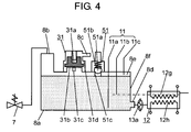
- FIG. 4 is a schematic diagram showing an example of the atmosphere open part of the sanitary cleansing device according to this exemplary embodiment.
- atmosphere open part 8 is configured by at least tank 8a having water inlet 8b, water outlet 8d, and atmosphere open hole 8c, water level sensor 11, vacuum braker 31, relief valve 51, and the like.
- Water inlet 8b of tank 8a is provided at an upstream side of tank 8a, and cleansing water such as tap water is injected in tank 8a via solenoid valve 7 of main body 200.
- Water outlet 8d of tank 8a flows cleansing water to heat exchanger 12 that is provided at a downstream side of tank 8a.
- Water level sensor 11 detects a water level of cleansing water stored in tank 8a, to output, for example, a conduction signal.
- Atmosphere open hole 8c of tank 8a is provided on an upper part of vacuum braker 31 provided in tank 8a, and an upper part of inside of tank 8a is opened to atmosphere, so that air layer 8e is formed.
- a pipe that guides cleansing water overflown from tank 8a due to failure into toilet bowl 700 is connected to atmosphere open hole 8c of tank 8a.
- tank 8a that configures atmosphere open part 8 temporarily stores cleansing water such as tap water supplied from a supply source, in which a temperature is fluctuated depending on a surrounding environment, and suppresses the temperature to almost an indoor environment temperature. That is, tank 8a acts as an inflow water temperature buffer part of cleansing water. Therefore, temperature dispersion of cleansing water that enters from the supply source is buffered to some extent, and cleansing water whose temperature is not rapidly changed can be supplied from tank 8a to heat exchanger 12. Consequently, a burden of electric power or the like can be reduced, when heater 12h of heat exchanger 12 heats cleansing water. Additionally, it is possible to further reduce discharge temperature irregularity of cleansing water along with temperature buffer action of buffer tank 15.
- Vacuum braker 31 is provided on an upper part of tank 8a, and prevents external leakage of the cleansing water in tank 8a in a case where tank 8a falls.
- Relief valve 51 is provided on the upper part of tank 8a, and opens (reduces) internal pressure in a case where internal pressure of tank 8a reaches predetermined pressure or more.
- Water level sensor 11 is configured by, for example, three electrodes of first sensor 11b, second sensor 11a, and third sensor 11c, lengths of which are different. Tip positions of first sensor 11b, second sensor 11a, and third sensor 11c are set so as to detect an upper limit water level or a lower limit water level by contact with cleansing water inside tank 8a.
- the lower limit water level is detected by a state where the longest second sensor 11a of water level sensor 11 is soaked in the cleansing water, and middle first sensor 11b is not soaked in the cleansing water, namely, by non-conduction between second sensor 11a and first sensor 11b.
- the tip position of first sensor 11b is disposed at at least the same position as, or a higher position than an upper end position 12g of heater 12h of heat exchanger 12 shown in FIG. 4 .
- the upper limit water level is detected in a case where tip positions of all of three first, second, third sensors 11b, 11a, and 11c are soaked in the cleansing water.
- water level sensor 11 shown in FIG. 4 is configured such that first sensor 11b, second sensor 11a, and third sensor 11c whose lengths are different are placed so as to protrude from the upper part of tank 8a in tank 8a, but is not limited to this.
- water level sensor 11 may be configured such that three sensors (not shown) whose lengths are the same are disposed at positions corresponding to the tip positions of first sensor 11b, second sensor 11a, and third sensor 11c whose lengths are different, shown in FIG. 4 , for example, high, middle and low height positions from side surface 8f of tank 8a. Consequently, the water level sensor can be configured by a single kind of sensors whose lengths are the same and short without using three kinds of sensors whose lengths are different. As a result, components that configure the sensors can be standardized from the three kinds to the single kind, and the sensors are configured by short sensors, thereby enabling reduction in a maintenance cost and a material cost.
- Relief valve 51 may be disposed at an upstream side of atmosphere open part 8, and may be integrated with solenoid valve 7. Consequently, atmosphere open part 8, a main body of the sanitary cleansing device, or the like can be made compact.
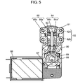
- FIG. 5 is a sectional view of the displacement pump of the sanitary cleansing device according to this exemplary embodiment.
- displacement pump 14 is configured by at least pump main body 81 having columnar space 82, pressure feeding piston 83, motor 86, link mechanism 89, and the like. At this time, pressure feeding piston 83 divides columnar space 82 of pump main body 81 into, pump chamber 82a and pump chamber 82b.
- Pump main body 81 has one side part provided with inflow parts 84 of cleansing water, and the other side part provided with outflow parts 85 of cleansing water.
- Inflow parts 84 are connected to heat exchanger 12 via cleansing water flow passage 202, and outflow parts 85 are connected to switching valve 16 via cleansing water flow passage 202.
- displacement pump 14 performs following operation.
- pressure feeding piston 83 by the upward and downward motion of pressure feeding piston 83, pressure is alternately applied to the cleansing water in pump chamber 82a and the cleansing water in pump chamber 82b. Additionally, reciprocating speed of pressure feeding piston 83 is changed during a single rotation, so that periodical pulsation can be applied to the cleansing water of inflow parts 84. At this time, as to pulsation pressure of the cleansing water, minimum pressure during pulsation is nearly equal to inflow pressure of displacement pump 14. On the other hand, maximum pressure of the pulsation pressure becomes pressure corresponding to a load of displacement pump 14 and speed of capacity change of displacement pump 14. Consequently, the cleansing water to which the pulsation pressure is applied is discharged from outflow parts 85 of displacement pump 14.
- opening to the atmosphere is allowed on an upstream side with respect to displacement pump 14 by atmosphere open part 8 inserted in cleansing water flow passage 202. That is, the inflow pressure of the cleansing water that flows into displacement pump 14 becomes atmospheric pressure (corresponding to 0 MPa at gauge pressure of an atmospheric pressure reference) without being affected by supply pressure of tap water being a supply source.
- cleansing water having a flow rate and pulsation pressure according to rotational speed of motor 86 of displacement pump 14 controlled by controller 4 are supplied to toilet bowl nozzle 40. Consequently, a jet flow of the cleansing water can be stably discharged into the toilet bowl from toilet bowl nozzle 40 at arbitrary pressure or an arbitrary flow rate without being affected by the supply pressure of the tap water being the supply source. As a result, the jet flow of the cleansing water discharged from toilet bowl nozzle 40 can be prevented from splashing outside the toilet bowl.
- An installation position in a height direction of displacement pump 14 is preferably installed at a position lower than a water level of atmosphere open part 8. Consequently, pump head capacity of displacement pump 14 is reduced, and an energy loss can be reduced.
- sanitary cleansing device 100 of this exemplary embodiment includes displacement pump 14 provided on an upstream side with respect to toilet bowl nozzle 40, atmosphere open part 8 that allows a part of cleansing water flow passage 202 disposed on the upstream side with respect to displacement pump 14 to be open to the atmosphere, and controller 4 that controls each part. Therefore, the flow rate of the cleansing water jetted from toilet bowl nozzle 40 and the maximum pressure of pulsation are not affected by supply pressure of tap water supplied from the tap water piping serving as the supply source. That is, the flow rate of the cleansing water jetted from toilet bowl nozzle 40 and the maximum pressure of pulsation can be arbitrarily adjusted in accordance with operation speed of displacement pump 14 by controller 4.
- the jet flow of the cleansing water discharged from toilet bowl nozzle 40 can be prevented from splashing outside the toilet bowl. Additionally, the toilet bowl surface is previously wetted by the jet flow of the cleansing water from toilet bowl nozzle 40, so that it is possible to prevent adhesion of feces. Furthermore, dirt already adhered to the toilet bowl surface can be effectively removed by the jet flow of the cleansing water from toilet bowl nozzle 40.
- the pressure of inflow parts 84 of displacement pump 14 becomes nearly atmospheric pressure. Therefore, the minimum pressure of the pulsation of displacement pump 14 becomes the atmospheric pressure.
- the maximum pressure of pulsation of the displacement pump 14 is changeable by a number of rotations of motor 86 of displacement pump 14, and the pulsation width can be increased.
- the toilet bowl is cleansed by the jet of the cleansing water from toilet bowl nozzle 40.
- the present invention is not limited thereto.
- the present invention may be applied to nozzle cleansing in a case where the private part of the human body is cleansed by buttock nozzle 1 or bidet nozzle 2 that serves as the cleansing nozzle, and operation and effects similar to those described below can be obtained.
- cleansing water on a primary side of displacement pump 14 is open to the atmosphere; therefore minimum pressure of pulsation pressure of cleansing water discharged from displacement pump 14 is atmospheric pressure, and maximum pressure is changeable by a number of rotations of motor 86 of displacement pump 14. Therefore, the flow rate is reduced by low speed rotation of motor 86 of displacement pump 14, so that it is possible to perform private part cleansing at small pressure amplitude of pulsation pressure with softer cleansing feeling.
- the flow rate of the cleansing water supplied to nozzle part 20 is increased by high speed rotation of motor 86 of displacement pump 14, so that pressure amplitude of pulsation pressure is increased, and it is possible to perform strong private part cleansing with stimulation feeling. That is, the pulsation width can be increased as the flow rate is increased. As a result, it is possible to provide a wider range of cleansing feeling to the user without being affected by the supply pressure of the tap water being the supply source.
- controller 4 controls the number of rotations of motor 86 to a flow rate according to water force set by water force setting switches 307 and 308 of the operation part of remote controller 300.
- sanitary cleansing device 100 of this exemplary embodiment performs variable control of the number of rotations of motor 86 of displacement pump 14 without providing any flow sensor or flow control valve, so that the flow rate of cleansing water can be controlled, and pulsation is applied to the cleansing water.
- sanitary cleansing device 100 of this exemplary embodiment includes water level sensor 11 that detects a water level of tank 8a, air layer 8e that opens the upper part of the inside of tank 8a to atmosphere, vacuum braker 31 that prevents external leakage of cleansing water in tank 8a, relief valve 51 that release the internal pressure of tank 8a, and the like, on an upper part of atmosphere open part 8 having tank 8a that stores cleansing water.
- water level sensor 11 that detects a water level of tank 8a
- air layer 8e that opens the upper part of the inside of tank 8a to atmosphere
- vacuum braker 31 that prevents external leakage of cleansing water in tank 8a
- relief valve 51 that release the internal pressure of tank 8a, and the like
- vacuum valve body 31a made of, for example, rubber, of vacuum braker 31 is generally in contact with lower valve seat 31b by gravity, so that the inside of tank 8a is brought into a seal state
- lower valve seat 31b of vacuum braker 31 includes communication slit 31c that serves as air vent. Therefore, communication slit 31c opens an upper part of the inside of tank 8a to the atmosphere to form air layer 8e.
- Vacuum braker 31 of this exemplary embodiment is provided in tank 8a. Therefore, in a case where a side close to the tap water piping that is the supply source becomes negative pressure, air is sucked from vacuum braker 31 provided in the upper part of tank 8a. As a result, cleansing water at the downstream side with respect to tank 8a can be prevented from flowing back to the tap water piping that is the supply source of the cleansing water.
- Relief valve 51 of this exemplary embodiment is configured by relief valve body 51a and relief spring 51b. Then, when tank 8a is turned upside down, set pressure of relief spring 51b of relief valve 51 is set to, for example, 0.1 MPa such that relief valve body 51a is not opened at water head pressure of the cleansing water. On the other hand, relief valve 51 is set so as to be opened at pressure lower than pressure at which tank 8a is damaged (for example, 0.4 MPa). Consequently, internal pressure of tank 8a is suppressed to a predetermined pressure or less, and reliability is enhanced.
- FIG. 6 is a time chart showing an example of operation of the sanitary cleansing device according to the first exemplary embodiment.
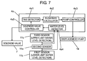
- FIG. 7 is a block diagram of the water level controller of the controller of the sanitary cleansing device according to the first exemplary embodiment.
- FIG. 6 shows a flow of operation from when a user enters a toilet room until when the user leaves a seat and leaves the room, in time series from time t1 to time t22.
- third sensor 11c of water level sensor 11 detects whether or not an amount of cleansing water in tank 8a is at the upper limit water level.
- the sanitary cleansing device is used, and after the user leaves the seat, water is supplied until the water level of tank 8a reaches a full level (upper limit water level) (until third sensor 11c detects the cleansing water), and preparation is made for next use.
- solenoid valve 7 is turned on and water is supplied until third sensor 11c detects the cleansing water.
- flow rate calculator 4s2 of water level controller 4s calculates a flow rate (referred to as flow rate reading in the figure), outputs a signal corresponding to the flow rate, and adjusts the number of rotations of displacement pump 14 through pump controller 4s3.
- flow rate calculator 4s2 first calculates an actual flow rate per unit time from reduction speed of the water level of tank 8a.
- controller 4 stops the toilet bowl cleansing and the preheating.
- a human body is detected, and in time t4 after, for example, 6 seconds, the user sits on a toilet seat.
- nozzle cleansing nozzle 3 After the user has relieved himself/herself, in time t5, when the user presses down buttock switch 303 (or bidet switch 304) of the operation part such as remote controller 300, nozzle cleansing nozzle 3 first performs nozzle cleansing at a position where buttock nozzle 1 (or bidet nozzle 2) is housed in a main body of the sanitary cleansing device. Then, after the nozzle cleansing is performed for a predetermined time, buttock nozzle 1 is made to protrude toward inside of the toilet bowl from the main body to a cleansing position, in time t6, and starts human body cleansing in time t7.
- the cleansing water in tank 8a is used, and displacement pump 14 and switching valve 16 are driven in accordance with a cleansing mode of each cleansing nozzle. Additionally, heater 12h of heat exchanger 12 is energized to heat cleansing water during use of the cleansing water.
- solenoid valve 7 When the water level of the inside of tank 8a is reduced up to first sensor 11b in time t8 during the human body cleansing with cleansing water force "weak", solenoid valve 7 is turned on while the human body cleansing is continued, and water is supplied till time t9 when third sensor 11c detects the upper limit water level (full level) of cleansing water.
- water flow rate calculator 4s2 of level controller 4s of controller 4 calculates an actual flow rate per unit time that is used during human body cleansing with "weak”, at timing of time t10 when the water level of the inside of tank 8a is reduced from third sensor 11c to second sensor 11a, and outputs a signal corresponding to the flow rate.
- water level controller 4s of controller 4 controls displacement pump 14 through pump controller 4s3, and corrects the number of rotations or the like to perform adjustment. Consequently, it is possible to accurately adjust a jetting amount of cleansing water controlled by displacement pump 14.
- the flow rate reading is not performed. That is, only in a case where the water level of the cleansing water in tank 8a is lowered from the upper limit water level of third sensor 11c to the lower limit water level of first sensor 11b in a single cleansing mode, the flow rate reading is performed, and adjustment by flow rate correction or the like is performed. Consequently, it is possible to accurately perform pumping at an accurate flow rate in each cleansing mode.
- an installation position is determined such that stored water quantity (capacity) of cleansing water between third sensor 11c and first sensor 11b of tank 8a is 60 cc. This reason is that, even in a case where the human body cleansing is performed, for example, at a minimum flow rate of about 300 cc/min (in a case where the buttock cleansing is performed with cleansing water force "weak") for only 15 seconds, a flow rate is always adjusted at least once.
- controller 4 and water level controller 4s stop driving of displacement pump 14, and heater 12h of heat exchanger 12. At this time, water is supplied until the water level of the cleansing water in tank 8a reaches the full level that is the upper limit water level (detected by third sensor 11c).
- controller 4 moves the cleansing nozzle from a protruding position to a housing position of the inside of the main body. Thereafter, in a period from time t17 to time t18, the nozzle that has been used at the housing position is after-cleansed, and the operation is stopped.
- water level controller 4s of controller 4 opens solenoid valve 7, and supplies cleansing water into tank 8a to make the cleansing water reach the full level.
- water level controller 4s of controller 4 suitably performs correction by a flow rate value measured by water level sensor 11, while basically controlling a flow rate of cleansing water discharged by displacement pump 14.
- the correction is not necessarily performed in each cleansing mode every time, but may be performed in a case where a flow rate gap is caused by variations in components, an influence of aged deterioration during use for a long period, or the like. Consequently, a proper flow rate can be jetted from the cleansing nozzle according to each cleansing mode for a long period.
- Controller 4 of sanitary cleansing device of this exemplary embodiment has a microcomputer (not shown), and previously stores an optimum flow rate in each cleansing mode, and an optimum flow rate in water force selected by the user. Then, controller 4 corrects the number of rotations of displacement pump 14 or the like based on output of water level sensor 11 to perform driving such that the flow rate becomes a flow rate corresponding to the cleansing mode.
- water level controller 4s of controller 4 of the sanitary cleansing device has at least time detector 4s1, flow rate calculator 4s2, pump controller 4s3, water level detector 4s4, and solenoid valve controller 4s5.
- Time detector 4s1 measures time until the water level of tank 8a reaches the lower limit water level from the upper limit water level, based on a signal of water level sensor 11.
- Flow rate calculator 4s2 calculates a flow rate discharged by displacement pump 14 by dividing a capacity from the upper limit water level to the lower limit water level of tank 8a (corresponding to a capacity of cleansing water) by the time measured by time detector 4s1.
- Pump controller 4s3 corrects and adjusts operation speed (the number of rotations, or the like) of displacement pump 14 such that the flow rate becomes a flow rate selected with water force setting switches 307 and 308 of the operation part by the user, based on a value of the flow rate calculated by flow rate calculator 4s2.
- Water level detector 4s4 detects the water level of the cleansing water in tank 8a, based on the signal detected by water level sensor 11 provided in tank 8a.
- Solenoid valve controller 4s5 controls solenoid valve 7 so as to maintain the cleansing water in tank 8a within a range from the upper limit water level to the lower limit water level, and supplies tap water into tank 8a.
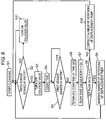
- FIG. 8 is a flowchart showing the correction operation of the water level controller of the controller in the sanitary cleansing device of this exemplary embodiment.
- FIG. 8 illustrates the correction operation of the water level controller in a case where the flow rate is reduced for a period from time t2 to time t3 of FIG. 6 , as an example.
- controller 4 first protrudes buttock nozzle 1 (or bidet nozzle 2) instructed by the operation part such as the remote controller 300, into toilet bowl 700 (nozzle protrusion). Then, a flow passage that leads to buttock nozzle 1 (or bidet nozzle 2) instructed by switching valve 16 is opened, and cleansing is started (Step S1).
- water level controller 4s causes water level detector 4s4 to determine whether or not third sensor 11c of water level sensor 11 is soaked in the cleansing water (Step S2). Second sensor 11a of water level sensor 11 is installed at the lowest position of a common sensor (is always soaked in the water).
- the water level of the cleansing water is at the upper limit water level of tank 8a. This state is determined by detection of a current between second sensor 11a and third sensor 11c of water level sensor 11 by water level detector 4s4.
- solenoid valve controller 4s5 of water level controller 4s controls so as to maintain a state where solenoid valve 7 is closed (turn off solenoid valve 7) (Step S3).
- Step S2 in a case where third sensor 11c of water level sensor 11 is not soaked in the cleansing water (NO in Step S2), a signal is output to solenoid valve controller 4s5 when water level detector 4s4 detects the lower limit water level at which first sensor 11b does not detect the cleansing water (not shown), solenoid valve 7 is turned on, and water is supplied up to the upper limit water level (Step S11).
- time detector 4s1 of water level controller 4s starts counting time from the state where third sensor 11c of water level sensor 11 is soaked in the cleansing water (Step S4).
- displacement pump 14 jets the cleansing water from buttock nozzle 1, so that the water level of the cleansing water in tank 8a is gradually lowered.
- Water level controller 4s causes water level detector 4s4 to determine whether or not first sensor 11b of water level sensor 11 is soaked in the cleansing water (Step S5). At this time, in a case where first sensor 11b of water level sensor 11 is not soaked in the cleansing water (NO in Step S5), the water level of the cleansing water is at the lower limit water level of tank 8a. That is, water level detector 4s4 does not detect a current between first sensor 11b and second sensor 11a. On the other hand, in a case where first sensor 11b of water level sensor 11 is soaked in the cleansing water (YES in Step S5), water level detector 4s4 waits until first sensor 11b is not soaked in the cleansing water.
- time detector 4s1 of water level controller 4s terminates the counting of the time (Step S6). Consequently, time t during which the cleansing water in tank 8a is reduced from the upper limit water level detected by third sensor 11c to the lower limit water level detected by first sensor 11b is measured.
- Water flow rate calculator 4s2 of level controller 4s calculates flow rate V by dividing capacity Q of the cleansing water in tank 8a from the upper limit water level detected by third sensor 11c to the lower limit water level detected by first sensor 11b, by time t described above.
- Step S8 set flow rate Vi previously jetted from displacement pump 14 in the cleansing mode is compared with flow rate V calculated in the above measurement (Step S8).
- pump controller 4s3 of water level controller 4s maintains the number of rotations of displacement pump 14 (Step S9), returns to Step S2, and performs similar processes subsequent to Step S2.
- pump controller 4s3 of water level controller 4s corrects and adjusts the number of rotations of displacement pump 14 such that set flow rate Vi is equal to calculated flow rate V (Step S10), returns to Step S2, and performs similar processes subsequent to Step S2.
- water level controller 4s of the sanitary cleansing device of this exemplary embodiment includes water level controller 4s that has at least time detector 4s1, flow rate calculator 4s2, and pump controller 4s3. Consequently, the operation speed (the number of rotations or the like) of displacement pump 14 is automatically adjusted so as to mantain a desired flow rate set with water force setting switches 307 and 308 by the user, without any additional flow sensor. Furthermore, in a case where a flow rate per unit time can be calculated based on the flow rate measured by water level sensor 11, the number of rotations of displacement pump 14 or the like can be corrected by use of a calculated value to perform control. As a result, it is possible to realize a downsized, compact and low-cost sanitary cleansing device that does not cause a gap with a set flow rate, and has a good feeling in use.
- relief valve 51 is not provided on a lower part or a bottom of tank 8a, but provided to face air layer 8e at the upper part of tank 8a. Therefore, valve seat contact surface 51c of relief valve body 51a is in the air in ordinary use, and therefore relief valve 51 is never exposed (soaked) to the cleansing water.
- relief valve 51 is not provided on the lower part or the bottom of tank 8a, but provided to face air layer 8e at the upper part of tank 8a, so that it is possible to further reduce a risk of no water heating by heat exchanger 12.
- controller 4 of this exemplary embodiment supplies water until the water level of the cleansing water in tank 8a reaches the upper limit water level (corresponding to a position of third sensor 11c), and thereafter solenoid valve controller 4s5 stops driving operation of solenoid valve 7 or the like. Consequently, the water level of the cleansing water in tank 8a can be made at a position higher than upper end position 12g of heater 12h of heat exchanger 12 shown in FIG. 4 . As a result, heater 12h of heat exchanger 12 is not exposed from the cleansing water, so that it is possible to prevent no water burning by heater 12h (no water heating of heat exchanger 12).
- Controller 4 of this exemplary embodiment causes the microcomputer of controller 4 to measure a predetermined time until the water level of the cleansing water in tank 8a normally sufficiently reaches the upper limit water level after solenoid valve 7 is opened (solenoid valve 7 is turned on). Then, in a case where solenoid valve 7 is not closed (solenoid valve 7 is not turned off) even when the measured predetermined time has elapsed, solenoid valve 7 is forcibly closed through solenoid valve controller 4s5 of water level controller 4s, and energization to heater 12h or the like is stopped. Consequently, even in a case where water level sensor 11 is broken, controller 4 can safely stop operation of main body 200 of the sanitary cleansing device.
- vacuum valve body 31a of vacuum braker 31 closes upper valve seat 31d to allow sealing.
- pressure in the tank is released from relief valve 51, and water is allow to escape into the toilet bowl.
- Controller 4 of this exemplary embodiment has water level controller 4s that maintains the water level of the inside of tank 8a and air layer 8e within predetermined ranges, by opening solenoid valve 7 when the water level of tank 8a is at the lower limit water level, and closing solenoid valve 7 when the water level is at the upper limit water level. Then, water level controller 4s controls opening/closing of solenoid valve 7 with the signal from water level sensor 11, thereby enabling a simple configuration that needs no reducing valve. Consequently, a water surface of tank 8a is maintained between the upper limit water level and the lower limit water level, and water is stably supplied to displacement pump 14 at water pressure in which the inside of the tank is open to the atmosphere. As a result, it is possible to realize a downsized and compact sanitary cleansing device.
- FIG. 9 is a schematic diagram of an atmosphere open part of the sanitary cleansing device according to the second exemplary embodiment of the present invention.
- the sanitary cleansing device of this exemplary embodiment is different from the sanitary cleansing device of the first exemplary embodiment in which atmosphere open part 8 and heat exchanger 12 are formed by separate components, in that atmosphere open part 8 and heat exchanger 12 are integrally formed.
- Other configurations are identical to those of the sanitary cleansing device of the first exemplary embodiment, and descriptions thereof are omitted.
- heater 12h of heat exchanger 12 is incorporated in and integrally formed with tank 8a of atmosphere open part 8.
- cleansing water is supplied so as to trace a surface of heater 12h of heat exchanger 12 from water inlet 8b of tank 8a. Consequently, heat exchange on the surface of heater 12h is facilitated, and the heat exchange efficiency to the cleansing water can be enhanced. As a result, warm water of the cleansing water stored in tank 8a is stirred, so that temperature irregularity of the cleansing water can be reduced.
- Other operation and effects are identical to those of the sanitary cleansing device of the first exemplary embodiment, and therefore descriptions thereof are omitted
- water inlet 8b is provided in the upper part of tank 8a so as to face air layer 8e.
- the position of water inlet 8b is not limited to this.
- water inlet 8b may be provided at at least a position where the cleansing water is present from a lower part of a side surface of tank 8a, so that the cleansing water is supplied into tank 8a. Consequently, it is possible to prevent generation of water supply noise in a case where water is supplied from the upper part of tank 8a to air layer 8e, or mixing of bubbles into the cleansing water in tank 8a. Additionally, the mixing of bubbles into the cleansing water is suppressed, so that it is possible to enhance reliability of water level detection of the cleansing water in tank 8a by water level sensor 11, and to improve measurement accuracy of a flow rate.
- water inlet 8b is provided on the lower part of the side surface of tank 8a.
- the position of water inlet 8b is not limited to this.
- water inlet 8b may be provided in the upper part of tank 8a so as to face air layer 8e. Consequently, the water supply noise can make the user recognize water supply of the cleansing water.
- the sanitary cleansing device includes the toilet bowl nozzle.
- the present invention is not limited to this.
- a sanitary cleansing device that includes no toilet bowl nozzle may be employed. Consequently, it is possible to realize a sanitary cleansing device having a simple configuration at a low cost.
- a sanitary cleansing device of the present invention includes: a cleansing nozzle configured to discharge cleansing water; and a cleansing water flow passage configured to allow the cleansing water from a supply source to flow toward the cleansing nozzle.
- the cleansing water flow passage has: a displacement pump configured to control a flow rate of the cleansing water discharged from the cleansing nozzle; an atmosphere open part disposed at an upstream side of the displacement pump, configured to open a part of the cleansing water flow passage to atmosphere, and having a tank for storing the cleansing water, and a water level sensor for detecting a water level in the tank to output a signal; a solenoid valve configured to pass and block the cleansing water supplied from the supply source to the atmosphere open part; and a controller configured to control the displacement pump and the solenoid valve. Furthermore, the controller calculates a flow rate of the cleansing water supplied per unit time from the supply source based on the signal of the water level sensor, and corrects control of the displacement pump.
- the displacement pump is disposed downstream of the atmosphere open part, so that the number of rotations of the displacement pump is controlled with no influence of supply pressure of the water supply source, and the flow rate of the cleansing water discharged from the cleansing nozzle is controlled. Furthermore, the water level sensor measures a flow rate of water that has actually passed, and feeds back the measured flow rate to the controller, so that contorol of the displacement pump is corrected. Consequently, with the correction of the flow rate detected by the water level sensor, the displacement pump can be controlled with no influence of variations in components, aged deterioration, or the like. As a result, it is possible to perform accurate and stable flow rate control over a long period without providing any flow sensor or flow control valve, and to realize a sanitary cleansing device that has a simple configuration and has a good feeling in use.
- the sanitary cleansing device of the present invention may include a heat exchanger having a heater for heating the cleansing water, between downstream of the atmosphere open part and upstream of the displacement pump, wherein the controller may control the heater.
- the water can be made to flow in the heat exchanger from the tank of the atmosphere open part by operation of the displacement pump, and therefore inflow water to the heat exchanger is stably controlled with no influence of supply pressure of the supply source.
- the displacement pump can reduce influence of a drawn flow rate due to an environmental factor of the supply source. Consequently, precision flow rate control improves precision of a heating temperature of the cleansing water by heating temperature control by the heater of the heat exchanger, and a stable jet can be discharged.
- the tank of the atmosphere open part may have a function of inflow water temperature buffer part.
- the temperature dispersion can be buffered to some extent. Therefore, cleansing water with no rapid temperature change can be supplied from the tank to the heat exchanger by the buffered cleansing water.
- the heater of the heat exchanger heats the cleansing water, a burden of electric power or the like can be reduced, and irregularity of a discharge temperature of the cleansing water can be prevented.
- the cleansing nozzle has a nozzle part including at least a private part cleansing nozzle for performing private part cleansing, and a bidet cleansing nozzle
- the sanitary cleansing device further includes an operation part configured to allow selection of a cleansing mode by the nozzle part.
- the controller may control a jet flow rate of the cleansing water in accordance with the cleansing mode of the nozzle part selected by the operation part, and correct flow rate control of the displacement pump based on a flow rate detected by the water level sensor at a time of cleansing in the cleansing mode selected by the operation part.
- the flow rate discharged from the displacement pump is corrected based on the flow rate detected by the water level sensor, to be controlled and adjusted, according to the cleansing mode selected by the operation part. Consequently, the flow rate according to the cleansing mode can be more accurately controlled by the displacement pump.
- the water level sensor may detect an upper limit water level and a lower limit water level in the tank
- the controller may have a water level controller configured to calculate a flow rate per unit time when the water level is changed from the upper limit water level to the lower limit water level, and a quantity of stored water from the lower limit water level to the upper limit water level may be set to be a quantity of water smaller than a total quantity of water used for a single standard cleansing time in any one of a plurality of the cleansing modes.
- the water level of the inside of the tank is changed from the upper limit water level to the lower limit water level at least once. Therefore, the flow rate per unit time is calculated, and the displacement pump is controlled, so that the flow rate of the cleansing water to be jetted is corrected. Therefore, the quantity of water stored in the tank can be minimized. Consequently, a main body can be downsized, and the flow rate can be suitably corrected without failure.
- the sanitary cleansing device of the present invention may include a heater of a heat exchanger is disposed inside the tank of the atmosphere open part for heating at least the stored cleansing water. Consequently, it is possible to reduce the number of components of the sanitary cleansing device. As a result, it is possible to realize a compact and low-cost sanitary cleansing device.
- the present invention is capable of stably supplying a jet flow having arbitrary pulsation from a cleansing nozzle, and therefore is useful not only for a warm water cleansing toilet seat, but a sanitary cleansing device for a face, a head, hands, feet, and the like, or a cleansing device for cleansing of animals such as pets or things other than living things.
Description
- The present invention relates to flow rate control of cleansing water in a sanitary cleansing device.
- Heretofore, in order to jet cleansing water to a private part of a human body at a proper temperature and a proper flow rate, various sanitary cleansing devices including high-precision flow sensors are developed (e.g., see
PTL 1, orUS 4 208 746 A ). - A sanitary cleansing device described in
PTL 1 includes a flow sensor at an upstream side of a heat exchanger for heating cleansing water. The flow sensor is configured by a swirl chamber in which cleansing water flows in a substantially U-shape, a rotor having a swirler, a photo interrupter, and the like. Then, the photo interrupter detects light interruption by the swirler rotated by the cleansing water that flows in the swirl chamber of the flow sensor, and detects a flow rate. Consequently, it is possible to detect the flow rate of the cleansing water with high detection precision, and to heat the cleansing water to a proper temperature with a heater of the heat exchanger. - However, in the above conventional configuration, a flow sensor having a complicated configuration is separately needed, and therefore a size of the sanitary cleansing device cannot be made compact, and there is a problem in costs. Additionally, there is a problem that a detection error is caused by bubbles mixed in the flow sensor along with the cleansing water.
- PTL 1:
Japanese Patent No. 3,620,215 - In order to solve the above problems, a sanitary cleansing device of the present invention includes: a cleansing nozzle configured to discharge cleansing water; and a cleansing water flow passage configured to allow the cleansing water from a supply source to flow toward the cleansing nozzle. The cleansing water flow passage has: a displacement pump configured to control a flow rate of the cleansing water discharged from the cleansing nozzle; an atmosphere open part disposed at an upstream side of the displacement pump, configured to open a part of the cleansing water flow passage to atmosphere, and having a tank for storing the cleansing water, and a water level sensor for detecting a water level in the tank to output a signal; a solenoid valve configured to pass and block the cleansing water supplied from the supply source to the atmosphere open part; and a controller configured to control the displacement pump and the solenoid valve. Furthermore, the controller calculates flow rate of the cleansing water supplied per unit time from the supply source based on the signal of the water level sensor, and corrects control of the displacement pump.
- According to this configuration, the displacement pump is disposed downstream of the atmosphere open part, so that a number of rotations of the displacement pump is controlled with no influence of supply pressure of the water supply source, and the flow rate of the cleansing water discharged from the cleansing nozzle is controlled. Furthermore, the water level sensor measures a flow rate of cleansing water that has actually passed, and feeds back the measured flow rate to the controller, so that the control of the displacement pump is corrected. Consequently, the flow rate detected by the water level sensor is corrected, and the flow rate of the cleansing water jetted from the displacement pump can be controlled with no influence of variations in components, aged deterioration, or the like. As a result, it is possible to perform accurate and stable flow rate control over a long period without providing any flow sensor or flow control valve, and to realize a sanitary cleansing device that has a simple configuration and has a good feeling in use.
-
-
FIG. 1 is a perspective view of a toilet device mounted with a sanitary cleansing device according to a first exemplary embodiment of the present invention. -
FIG. 2 is a front view of a remote controller of the sanitary cleansing device according to the first exemplary embodiment. -
FIG. 3 is a schematic diagram showing a configuration of a main body of the sanitary cleansing device according to the first exemplary embodiment. -
FIG. 4 is a schematic diagram showing an example of an atmosphere open part of the sanitary cleansing device according to the first exemplary embodiment. -
FIG. 5 is a sectional view of a displacement pump of the sanitary cleansing device according to the first exemplary embodiment. -
FIG. 6 is a time chart showing an example of operation of the sanitary cleansing device according to the first exemplary embodiment. -
FIG. 7 is a block diagram of a water level controller of a controller of the sanitary cleansing device according to the first exemplary embodiment. -
FIG. 8 is a flowchart showing correction operation of water level controller of the controller of the sanitary cleansing device according to the first exemplary embodiment. -
FIG. 9 is a schematic diagram of an atmosphere open part of a sanitary cleansing device according to a second exemplary embodiment of the present invention. - Hereinafter, a sanitary cleansing device according to exemplary embodiments of the present invention will be described with reference to the drawings. It should be noted that the present invention is not limited by these exemplary embodiments.
- Hereinafter, a sanitary cleansing device according to a first exemplary embodiment of the present invention, and a toilet device with the same will be described with reference to
FIG. 1 . -
FIG. 1 is a perspective view of the toilet device mounted with the sanitary cleansing device according to the first exemplary embodiment of the present invention.Toilet device 1000 is installed in a toilet room. - As shown in
FIG. 1 ,toilet device 1000 of this exemplary embodiment includes at leastsanitary cleansing device 100,toilet bowl 700, roomentry detection sensor 600, and the like, and is mounted withsanitary cleansing device 100 ontoilet bowl 700. -
Sanitary cleansing device 100 is configured bymain body 200,remote controller 300,toilet seat 400,lid 500, and the like.Main body part 200 incorporates a cleansing water supply mechanism (seeFIG. 3 ) that is controlled by sittingsensor 610 andcontroller 4 provided on a front upper part, and is openably mounted withtoilet seat 400 andlid 500. Sittingsensor 610 is configured by, for example, a reflective infrared sensor, and detects an infrared ray reflected from a human body, to detect whether or not a user is present ontoilet seat 400. - The cleansing water supply mechanism incorporated in
main body 200 has one end connected totoilet bowl nozzle 40 provided on a front lower part ofmain body 200 and the other end connected to a tap water piping.FIG. 1 shows a state wheretoilet bowl nozzle 40 protrudes insidetoilet bowl 700. Consequently, the cleansing water supply mechanism supplies cleansing water supplied from the tap water piping totoilet bowl nozzle 40. In a case of pre-cleansing of the toilet bowl, the supplied cleansing water is jetted fromtoilet bowl nozzle 40 into a wide range of an inner surface oftoilet bowl 700. In a case of back part cleansing of the toilet bowl, the cleansing water is jetted fromtoilet bowl nozzle 40 to a rear surface side of the inner surface oftoilet bowl 700. - Furthermore, a cleansing water supply mechanism incorporated in
main body 200 is connected tonozzle part 20 configured bybuttock nozzle 1 that serves as a private part cleansing nozzle,bidet nozzle 2 that serves as a bidet cleansing nozzle,nozzle cleansing nozzle 3,toilet bowl nozzle 40, and the like, which configure a cleansing nozzle (seeFIG. 3 ). Consequently, the cleansing water supply mechanism supplies cleansing water supplied from a tap water piping, to nozzlepart 20. Then, the supplied cleansing water is jetted frombuttock nozzle 1,bidet nozzle 2, or the like to a private part of a user. Additionally, cleansing water supplied tonozzle cleansing nozzle 3 ofnozzle part 20 is jet tonozzle part 20 such asbuttock nozzle 1 andbidet nozzle 2, thereby cleansing the nozzles. - Operation part such as
remote controller 300 has a plurality of switches for selecting cleansing modes of cleansing a plurality of cleansing nozzles, and is mounted on, for example, a place where the user sitting ontoilet seat 400 can operate. - Room
entry detection sensor 600 is configured by, for example, a reflective infrared sensor, and is mounted on an entrance of the toilet room or the like. In a case where roomentry detection sensor 600 detects an infrared ray reflected from the human body, roomentry detection sensor 600 detects that the user entered the toilet room. - Controller 4 (see
FIG. 3 ) ofmain body 200 controls operation of respective parts ofsanitary cleansing device 100 based on signals transmitted fromremote controller 300, roomentry detection sensor 600, andsitting sensor 610. - Hereinafter, a configuration of
remote controller 300 ofsanitary cleansing device 100 according to this exemplary embodiment will be described with reference toFIG. 2 . -
FIG. 2 is a front view of the remote controller of the sanitary cleansing device according to this exemplary embodiment. - As shown in
FIG. 2 ,remote controller 300 includeswide cleansing switch 305,rhythm cleansing switch 306, waterforce setting switches cleansing switch 309, and cleansingposition setting switches main body 301, andstop switch 302 for instructing cleansing operation,buttock switch 303, andbidet switch 304 which are provided on a lower part of controllermain body 301. - As shown in
FIG. 1 , when the user operates the respective switches of the operation part ofremote controller 300, predetermined signals according to the respective switches ofmain body 200 are transmitted fromremote controller 300, for example, by radio. Controller 4 (seeFIG. 3 ) ofmain body 200 controls operation of respective components ofmain body 200 andtoilet seat 400 based on the received signals. For example, in a case where the user depressesbuttock cleansing button 303 orbidet cleansing button 304,controller 4 movesnozzle part 20 ofmain body 200, such asbuttock nozzle 1 andbidet nozzle 2, jets cleansing water, and cleanses the private part of the user. At this time, the user sets one of a plurality of water force levels from cleansing water force "weak" to cleansing water force "strong" with waterforce setting switches controller 4 controls quantity of cleansing water to be jetted fromnozzle part 20, to cleanse the private part. - Hereinafter, configurations and actions of a water supply system and a control system in
main body 200 ofsanitary cleansing device 100 of this exemplary embodiment will be described with reference toFIG. 3 . -
FIG. 3 is a schematic diagram showing a configuration of the main body of the sanitary cleansing device according to this exemplary embodiment. - As shown in
FIG. 3 ,main body 200 ofsanitary cleansing device 100 is configured bycontroller 4 havingwater level controller 4s,branch faucet 5,strainer 6,solenoid valve 7, atmosphereopen part 8,flow regulating valve 9,heat exchanger 12,temperature sensors displacement pump 14,buffer tank 15, switchingvalve 16,nozzle part 20, toiletbowl nozzle motor 40m, and the like. As described above,nozzle part 20 ofmain body 200 is configured bybuttock nozzle 1,bidet nozzle 2, andnozzle cleansing nozzle 3,toilet bowl nozzle 40, and the like, and switchingvalve 16 includes switchingvalve motor 16m. - As shown in
FIG. 3 ,branch faucet 5 is inserted intotap water piping 201 that serves as a supply source of cleansing water, and is connected to cleansingwater flow passage 202 that reachesbuttock nozzle 1 andbidet nozzle 2 which configure the cleansing nozzle. Into cleansingwater flow passage 202,strainer 6,flow regulating valve 9,solenoid valve 7, atmosphereopen part 8 havingtank 8a includingvacuum braker 31 andrelief valve 51,temperature sensor 13a,heat exchanger 12,temperature sensor 13b,buffer tank 15,displacement pump 14, and switchingvalve 16 are sequentially inserted frombranch faucet 5. - Furthermore,
toilet bowl nozzle 40 that configuresnozzle part 20 is connected to an end of toilet bowl cleansingwater flow passage 205 branched from cleansingwater flow passage 202 by switchingvalve 16.Toilet bowl nozzle 40 is mounted with toiletbowl nozzle motor 40m. - Now, flow of cleansing water in
main body 200 ofsanitary cleansing device 100, and control of the respective components ofmain body 200 bycontroller 4 will be described with reference toFIG. 3 . - First, as shown in
FIG. 3 , tap water that flows throughtap water piping 201 is supplied tostrainer 6 as cleansing water bybranch faucet 5. Then,strainer 6 removes dust, impurities, and the like included in the cleansing water. -
Controller 4controls solenoid valve 7 to switch a supply state of the cleansing water. At this time, pressure of cleansing water that passes throughflow regulating valve 9 formed from a rubber variable orifice having an orifice diameter changed by action water pressure, and flows in cleansingwater flow passage 202 is reduced. - The cleansing water controlled by
solenoid valve 7 is supplied toheat exchanger 12 having a heater provided downstream of atmosphereopen part 8, and upstream ofdisplacement pump 14, via atmosphereopen part 8 which is hereinafter described in detail. -
Heater 12h ofheat exchanger 12 heats the cleansing water supplied through cleansingwater flow passage 202 to a predetermined temperature (temperature set by a cleansing temperature setting part (not shown) of the operation part such as the remote controller), for example, 39°C. At this time, displacement pump 14 (hereinafter, referred to as a "displacement pump") that serves as a pulsation pump connected toheat exchanger 12 is driven and controlled bywater level controller 4s ofcontroller 4, and cleansing water having a flow rate according to operation speed ofdisplacement pump 14 is discharged frombuttock nozzle 1 orbidet nozzle 2 that serves as the cleansing nozzle. Therefore,controller 4 controls heating operation byheater 12h ofheat exchanger 12 based on measured temperature values measured bytemperature sensors displacement pump 14. - The cleansing water heated by
heater 12h ofheat exchanger 12 is pumped to switchingvalve 16 throughbuffer tank 15 bydisplacement pump 14. Then, switchingvalve 16 is switched tobuttock nozzle 1 orbidet nozzle 2 that serves as the human body cleansing nozzle, ornozzle cleansing nozzle 3 for cleansing a nozzle, bycontroller 4. Additionally, switchingvalve 16 is switched totoilet bowl nozzle 40 that discharges the cleansing water to a toilet bowl surface in order to perform the pre-cleansing of the toilet bowl, back part cleansing of the toilet bowl, and the like. - At this time,
buffer tank 15 acts as a temperature buffer part of the heated cleansing water. That is, the cleansing water pumped to switchingvalve 16 controls generation of temperature irregularity. Total capacity ofheat exchanger 12 andbuffer tank 15 is preferably from 15 cc to 30 cc, and more preferably from 20 cc to 25 cc. Consequently, in a general sanitary cleansing device, temperature fluctuation of cleansing water can be suppressed with optimum responsiveness. - Then,
controller 4 controls operation of switchingvalve motor 16m, switchingvalve 16 is switched to any ofbuttock nozzle 1,bidet nozzle 2,nozzle cleansing nozzle 3, andtoilet bowl nozzle 40, which configurenozzle part 20 of the cleansing nozzle, and the cleansing water pumped fromdisplacement pump 14 is supplied. Consequently, the cleansing water is jetted from any ofbuttock nozzle 1,bidet nozzle 2,nozzle cleansing nozzle 3, andtoilet bowl nozzle 40. -
Buttock nozzle 1, andbidet nozzle 2 are used to cleanse the private part of the user.Nozzle cleansing nozzle 3 is used to cleanse parts ofbuttock nozzle 1 andbidet nozzle 2 that protrude insidetoilet bowl 700. Furthermore,toilet bowl nozzle 40 is used to cleanse the inside of the toilet bowl. - Now, the atmosphere open part provided in the main body of the sanitary cleansing device according to this exemplary embodiment will be described with reference to
FIG. 4 . -
FIG. 4 is a schematic diagram showing an example of the atmosphere open part of the sanitary cleansing device according to this exemplary embodiment. - As shown in
FIG. 4 , atmosphereopen part 8 is configured by at leasttank 8a havingwater inlet 8b,water outlet 8d, and atmosphereopen hole 8c,water level sensor 11,vacuum braker 31,relief valve 51, and the like.Water inlet 8b oftank 8a is provided at an upstream side oftank 8a, and cleansing water such as tap water is injected intank 8a viasolenoid valve 7 ofmain body 200.Water outlet 8d oftank 8a flows cleansing water toheat exchanger 12 that is provided at a downstream side oftank 8a.Water level sensor 11 detects a water level of cleansing water stored intank 8a, to output, for example, a conduction signal. Atmosphereopen hole 8c oftank 8a is provided on an upper part ofvacuum braker 31 provided intank 8a, and an upper part of inside oftank 8a is opened to atmosphere, so thatair layer 8e is formed. Although the figure does not show, a pipe that guides cleansing water overflown fromtank 8a due to failure intotoilet bowl 700 is connected to atmosphereopen hole 8c oftank 8a. - At this time,
tank 8a that configures atmosphereopen part 8 temporarily stores cleansing water such as tap water supplied from a supply source, in which a temperature is fluctuated depending on a surrounding environment, and suppresses the temperature to almost an indoor environment temperature. That is,tank 8a acts as an inflow water temperature buffer part of cleansing water. Therefore, temperature dispersion of cleansing water that enters from the supply source is buffered to some extent, and cleansing water whose temperature is not rapidly changed can be supplied fromtank 8a toheat exchanger 12. Consequently, a burden of electric power or the like can be reduced, whenheater 12h ofheat exchanger 12 heats cleansing water. Additionally, it is possible to further reduce discharge temperature irregularity of cleansing water along with temperature buffer action ofbuffer tank 15. -
Vacuum braker 31 is provided on an upper part oftank 8a, and prevents external leakage of the cleansing water intank 8a in a case wheretank 8a falls.Relief valve 51 is provided on the upper part oftank 8a, and opens (reduces) internal pressure in a case where internal pressure oftank 8a reaches predetermined pressure or more.Water level sensor 11 is configured by, for example, three electrodes offirst sensor 11b,second sensor 11a, andthird sensor 11c, lengths of which are different. Tip positions offirst sensor 11b,second sensor 11a, andthird sensor 11c are set so as to detect an upper limit water level or a lower limit water level by contact with cleansing water insidetank 8a. For example, the lower limit water level is detected by a state where the longestsecond sensor 11a ofwater level sensor 11 is soaked in the cleansing water, and middlefirst sensor 11b is not soaked in the cleansing water, namely, by non-conduction betweensecond sensor 11a andfirst sensor 11b. At this time, the tip position offirst sensor 11b is disposed at at least the same position as, or a higher position than anupper end position 12g ofheater 12h ofheat exchanger 12 shown inFIG. 4 . On the other hand, the upper limit water level is detected in a case where tip positions of all of three first, second,third sensors - As described above,
water level sensor 11 shown inFIG. 4 is configured such thatfirst sensor 11b,second sensor 11a, andthird sensor 11c whose lengths are different are placed so as to protrude from the upper part oftank 8a intank 8a, but is not limited to this. For example,water level sensor 11 may be configured such that three sensors (not shown) whose lengths are the same are disposed at positions corresponding to the tip positions offirst sensor 11b,second sensor 11a, andthird sensor 11c whose lengths are different, shown inFIG. 4 , for example, high, middle and low height positions fromside surface 8f oftank 8a. Consequently, the water level sensor can be configured by a single kind of sensors whose lengths are the same and short without using three kinds of sensors whose lengths are different. As a result, components that configure the sensors can be standardized from the three kinds to the single kind, and the sensors are configured by short sensors, thereby enabling reduction in a maintenance cost and a material cost. -
Relief valve 51 may be disposed at an upstream side of atmosphereopen part 8, and may be integrated withsolenoid valve 7. Consequently, atmosphereopen part 8, a main body of the sanitary cleansing device, or the like can be made compact. - Now, a configuration and operation of the displacement pump that serves as the pulsation pump provided in the main body of the sanitary cleansing device will be described with reference to
FIG. 5 . -
FIG. 5 is a sectional view of the displacement pump of the sanitary cleansing device according to this exemplary embodiment. - As shown in
FIG. 5 ,displacement pump 14 is configured by at least pumpmain body 81 havingcolumnar space 82,pressure feeding piston 83,motor 86,link mechanism 89, and the like. At this time,pressure feeding piston 83 divides columnarspace 82 of pumpmain body 81 into, pumpchamber 82a and pumpchamber 82b. - Pump
main body 81 has one side part provided withinflow parts 84 of cleansing water, and the other side part provided withoutflow parts 85 of cleansing water.Inflow parts 84 are connected toheat exchanger 12 via cleansingwater flow passage 202, andoutflow parts 85 are connected to switchingvalve 16 via cleansingwater flow passage 202. -
Gear 87 mounted on a rotational shaft ofmotor 86, and gear 88 connected to linkmechanism 89 mesh with each other, so that rotary motion ofmotor 86 is converted into reciprocating motion ofpressure feeding piston 83 vialink mechanism 89. That is, whenmotor 86 rotates,pressure feeding piston 83 reciprocates viagear 87, gear 88, andlink mechanism 89. - Consequently,
displacement pump 14 performs following operation. - When
pressure feeding piston 83 moves downward, and capacity ofpump chamber 82a increases, pressure ofpump chamber 82a becomes lower than pressure ofinflow parts 84. Therefore, cleansing water insideheat exchanger 12 is supplied frominflow part 84a to pumpchamber 82a. - On the other hand, when
pressure feeding piston 83 moves upward and capacity ofpump chamber 82a is reduced, the pressure ofpump chamber 82a becomes higher than pressure ofoutflow parts 85. Therefore, cleansing water supplied to pumpchamber 82a is discharged tooutflow part 85a. - Consequently, when the cleansing water in
pump chamber 82a is discharged fromoutflow part 85a, the cleansing water is supplied intopump chamber 82b frominflow part 84b. Then, when the cleansing water inpump chamber 82a is supplied frominflow part 84a, the cleansing water inpump chamber 82b is discharged fromoutflow part 85b. - That is, by the upward and downward motion of
pressure feeding piston 83, pressure is alternately applied to the cleansing water inpump chamber 82a and the cleansing water inpump chamber 82b. Additionally, reciprocating speed ofpressure feeding piston 83 is changed during a single rotation, so that periodical pulsation can be applied to the cleansing water ofinflow parts 84. At this time, as to pulsation pressure of the cleansing water, minimum pressure during pulsation is nearly equal to inflow pressure ofdisplacement pump 14. On the other hand, maximum pressure of the pulsation pressure becomes pressure corresponding to a load ofdisplacement pump 14 and speed of capacity change ofdisplacement pump 14. Consequently, the cleansing water to which the pulsation pressure is applied is discharged fromoutflow parts 85 ofdisplacement pump 14. - At this time, as shown in
FIG. 3 , opening to the atmosphere is allowed on an upstream side with respect todisplacement pump 14 by atmosphereopen part 8 inserted in cleansingwater flow passage 202. That is, the inflow pressure of the cleansing water that flows intodisplacement pump 14 becomes atmospheric pressure (corresponding to 0 MPa at gauge pressure of an atmospheric pressure reference) without being affected by supply pressure of tap water being a supply source. - Therefore, for example, in a case where switching
valve 16 switches totoilet bowl nozzle 40, cleansing water having a flow rate and pulsation pressure according to rotational speed ofmotor 86 ofdisplacement pump 14 controlled bycontroller 4 are supplied totoilet bowl nozzle 40. Consequently, a jet flow of the cleansing water can be stably discharged into the toilet bowl fromtoilet bowl nozzle 40 at arbitrary pressure or an arbitrary flow rate without being affected by the supply pressure of the tap water being the supply source. As a result, the jet flow of the cleansing water discharged fromtoilet bowl nozzle 40 can be prevented from splashing outside the toilet bowl. An installation position in a height direction ofdisplacement pump 14 is preferably installed at a position lower than a water level of atmosphereopen part 8. Consequently, pump head capacity ofdisplacement pump 14 is reduced, and an energy loss can be reduced. - That is,
sanitary cleansing device 100 of this exemplary embodiment includesdisplacement pump 14 provided on an upstream side with respect totoilet bowl nozzle 40, atmosphereopen part 8 that allows a part of cleansingwater flow passage 202 disposed on the upstream side with respect todisplacement pump 14 to be open to the atmosphere, andcontroller 4 that controls each part. Therefore, the flow rate of the cleansing water jetted fromtoilet bowl nozzle 40 and the maximum pressure of pulsation are not affected by supply pressure of tap water supplied from the tap water piping serving as the supply source. That is, the flow rate of the cleansing water jetted fromtoilet bowl nozzle 40 and the maximum pressure of pulsation can be arbitrarily adjusted in accordance with operation speed ofdisplacement pump 14 bycontroller 4. Consequently, the jet flow of the cleansing water discharged fromtoilet bowl nozzle 40 can be prevented from splashing outside the toilet bowl. Additionally, the toilet bowl surface is previously wetted by the jet flow of the cleansing water fromtoilet bowl nozzle 40, so that it is possible to prevent adhesion of feces. Furthermore, dirt already adhered to the toilet bowl surface can be effectively removed by the jet flow of the cleansing water fromtoilet bowl nozzle 40. - Hereinafter, reasons why the above operation and effects are obtained will be described.
- Generally, in a case where the supply pressure of tap water acts on
inflow parts 84 ofdisplacement pump 14, the minimum pressure of the pulsation ofdisplacement pump 14 becomes the supply pressure of tap water. At this time, when a load is constant at the maximum pressure of pulsation, the load is hardly changed, and therefore a pulsation width is reduced. - However, as in this exemplary embodiment, when opening to the atmosphere is allowed on the upstream side with respect to
displacement pump 14 by atmosphereopen part 8 of cleansingwater flow passage 202, the pressure ofinflow parts 84 ofdisplacement pump 14 becomes nearly atmospheric pressure. Therefore, the minimum pressure of the pulsation ofdisplacement pump 14 becomes the atmospheric pressure. On the other hand, the maximum pressure of pulsation of thedisplacement pump 14 is changeable by a number of rotations ofmotor 86 ofdisplacement pump 14, and the pulsation width can be increased. - In this exemplary embodiment, the toilet bowl is cleansed by the jet of the cleansing water from
toilet bowl nozzle 40. However, the present invention is not limited thereto. For example, the present invention may be applied to nozzle cleansing in a case where the private part of the human body is cleansed bybuttock nozzle 1 orbidet nozzle 2 that serves as the cleansing nozzle, and operation and effects similar to those described below can be obtained. - That is, as described above, cleansing water on a primary side of
displacement pump 14 is open to the atmosphere; therefore minimum pressure of pulsation pressure of cleansing water discharged fromdisplacement pump 14 is atmospheric pressure, and maximum pressure is changeable by a number of rotations ofmotor 86 ofdisplacement pump 14. Therefore, the flow rate is reduced by low speed rotation ofmotor 86 ofdisplacement pump 14, so that it is possible to perform private part cleansing at small pressure amplitude of pulsation pressure with softer cleansing feeling. On the other hand, the flow rate of the cleansing water supplied tonozzle part 20 is increased by high speed rotation ofmotor 86 ofdisplacement pump 14, so that pressure amplitude of pulsation pressure is increased, and it is possible to perform strong private part cleansing with stimulation feeling. That is, the pulsation width can be increased as the flow rate is increased. As a result, it is possible to provide a wider range of cleansing feeling to the user without being affected by the supply pressure of the tap water being the supply source. - Then, the number of rotations of
displacement pump 14 is controlled, so that the flow rate of the cleansing water discharged from the cleansing nozzle is controlled, andcontroller 4 controls the number of rotations ofmotor 86 to a flow rate according to water force set by waterforce setting switches remote controller 300. With this control, a user's desired flow rate is precisely maintained, thereby enabling an optimum flow rate in each cleansing. As a result, it is possible to realize a sanitary cleansing device with a good feeling in use. - As described above,
sanitary cleansing device 100 of this exemplary embodiment performs variable control of the number of rotations ofmotor 86 ofdisplacement pump 14 without providing any flow sensor or flow control valve, so that the flow rate of cleansing water can be controlled, and pulsation is applied to the cleansing water. - As shown in
FIG. 4 ,sanitary cleansing device 100 of this exemplary embodiment includeswater level sensor 11 that detects a water level oftank 8a,air layer 8e that opens the upper part of the inside oftank 8a to atmosphere, vacuum braker 31 that prevents external leakage of cleansing water intank 8a,relief valve 51 that release the internal pressure oftank 8a, and the like, on an upper part of atmosphereopen part 8 havingtank 8a that stores cleansing water. For example, in a case wheretank 8a is inclined to be turned upside down, and the cleansing water intank 8a is about to be flown out whensanitary cleansing device 100 is detached fromtoilet bowl 700, and clean the toilet bowl,vacuum valve body 31a ofvacuum braker 31 closesupper valve seat 31d. Consequently, it is possible to close a flow passage that allows cleansing water to leak fromtank 8a to outside. As a result, cleansing water can be prevented from leaking/dropping fromtank 8a onto a floor or the like. - While
vacuum valve body 31a made of, for example, rubber, ofvacuum braker 31 is generally in contact withlower valve seat 31b by gravity, so that the inside oftank 8a is brought into a seal state,lower valve seat 31b ofvacuum braker 31 includescommunication slit 31c that serves as air vent. Therefore,communication slit 31c opens an upper part of the inside oftank 8a to the atmosphere to formair layer 8e. -
Vacuum braker 31 of this exemplary embodiment is provided intank 8a. Therefore, in a case where a side close to the tap water piping that is the supply source becomes negative pressure, air is sucked fromvacuum braker 31 provided in the upper part oftank 8a. As a result, cleansing water at the downstream side with respect totank 8a can be prevented from flowing back to the tap water piping that is the supply source of the cleansing water. -
Relief valve 51 of this exemplary embodiment is configured byrelief valve body 51a andrelief spring 51b. Then, whentank 8a is turned upside down, set pressure ofrelief spring 51b ofrelief valve 51 is set to, for example, 0.1 MPa such thatrelief valve body 51a is not opened at water head pressure of the cleansing water. On the other hand,relief valve 51 is set so as to be opened at pressure lower than pressure at whichtank 8a is damaged (for example, 0.4 MPa). Consequently, internal pressure oftank 8a is suppressed to a predetermined pressure or less, and reliability is enhanced. - Hereinafter, operation of the sanitary cleansing device of this exemplary embodiment will be described with reference to
FIG. 1 ,FIG. 3 ,FIG. 6 andFIG. 7 . -
FIG. 6 is a time chart showing an example of operation of the sanitary cleansing device according to the first exemplary embodiment.FIG. 7 is a block diagram of the water level controller of the controller of the sanitary cleansing device according to the first exemplary embodiment. -
FIG. 6 shows a flow of operation from when a user enters a toilet room until when the user leaves a seat and leaves the room, in time series from time t1 to time t22. Each item of operation ofsolenoid valve 7, a water level oftank 8a, output of a signal for regulating a flow rate fromwater level controller 4s, an operation mode ofdisplacement pump 14, a switching flow passage of switchingvalve 16, andheater 12h ofheat exchanger 12, shown inFIG. 6 shows operation corresponding to time series from time t1 to time t22. - As shown in
FIG. 6 andFIG. 7 , in time t1, when roomentry detection sensor 600 detects that the user has entered the toilet room,third sensor 11c ofwater level sensor 11 detects whether or not an amount of cleansing water intank 8a is at the upper limit water level. Generally, the sanitary cleansing device is used, and after the user leaves the seat, water is supplied until the water level oftank 8a reaches a full level (upper limit water level) (untilthird sensor 11c detects the cleansing water), and preparation is made for next use. However, in a case where the water level oftank 8a does not reach the full level (upper limit water level) when the entry of the user is detected,solenoid valve 7 is turned on and water is supplied untilthird sensor 11c detects the cleansing water. - Then, when the cleansing water in
tank 8a is at the upper limit water level,displacement pump 14 is driven, and switchingvalve 16 is switched to a flow passage for toilet bowl cleansing to start toilet bowl cleansing. At the same time,heater 12h ofheat exchanger 12 is energized, and "preheating" for previously heating the cleansing water intank 8a is performed. - In time t2 during toilet bowl cleansing, when the cleansing water is reduced up to
first sensor 11b that detects the lower limit water level, flow rate calculator 4s2 ofwater level controller 4s calculates a flow rate (referred to as flow rate reading in the figure), outputs a signal corresponding to the flow rate, and adjusts the number of rotations ofdisplacement pump 14 through pump controller 4s3. At this time,displacement pump 14 is driven at the number of rotations previously set in a cleansing mode of toilet bowl cleansing. However, a gap between a flow rate actually discharged, and a set flow rate previously set in the toilet bowl cleansing may be caused by aged deterioration, variations in components, or the like. Therefore, flow rate calculator 4s2 first calculates an actual flow rate per unit time from reduction speed of the water level oftank 8a. Then, when a gap between the actual flow rate and the set flow rate in toilet bowl cleansing is present, the number of rotations ofdisplacement pump 14 or the like is corrected to be adjusted based on a value of the calculated flow rate. Consequently, it is possible to pump out cleansing water from inside oftank 8a at a more accurate flow rate. - In time t3,
controller 4 stops the toilet bowl cleansing and the preheating. - Then, a human body is detected, and in time t4 after, for example, 6 seconds, the user sits on a toilet seat.
- After the user has relieved himself/herself, in time t5, when the user presses down buttock switch 303 (or bidet switch 304) of the operation part such as
remote controller 300,nozzle cleansing nozzle 3 first performs nozzle cleansing at a position where buttock nozzle 1 (or bidet nozzle 2) is housed in a main body of the sanitary cleansing device. Then, after the nozzle cleansing is performed for a predetermined time,buttock nozzle 1 is made to protrude toward inside of the toilet bowl from the main body to a cleansing position, in time t6, and starts human body cleansing in time t7. - At this time, during the nozzle cleansing, the cleansing water in
tank 8a is used, anddisplacement pump 14 and switchingvalve 16 are driven in accordance with a cleansing mode of each cleansing nozzle. Additionally,heater 12h ofheat exchanger 12 is energized to heat cleansing water during use of the cleansing water. - Following description covers an example of a case where the user first sets cleansing water force "weak" with the operation part such as
remote controller 300 such as remote control, starts human body cleansing for a period from time t7 to time t12, changes cleansing water force to "strong", and performs human body cleansing for a period from time t12 to time t16. - When the water level of the inside of
tank 8a is reduced up tofirst sensor 11b in time t8 during the human body cleansing with cleansing water force "weak",solenoid valve 7 is turned on while the human body cleansing is continued, and water is supplied till time t9 whenthird sensor 11c detects the upper limit water level (full level) of cleansing water. - Then, during buttock cleansing with cleansing water force "weak", water flow rate calculator 4s2 of
level controller 4s ofcontroller 4 calculates an actual flow rate per unit time that is used during human body cleansing with "weak", at timing of time t10 when the water level of the inside oftank 8a is reduced fromthird sensor 11c tosecond sensor 11a, and outputs a signal corresponding to the flow rate. At this time, when a gap between a set flow rate with water force of buttock cleansing "weak" previously set, and an actual flow rate is present,water level controller 4s ofcontroller 4controls displacement pump 14 through pump controller 4s3, and corrects the number of rotations or the like to perform adjustment. Consequently, it is possible to accurately adjust a jetting amount of cleansing water controlled bydisplacement pump 14. In time t8, when the water level of the cleansing water intank 8a is lowered up tofirst sensor 11b that detects the lower limit water level, water supply is needed. However, in this case, the flow rate is not adjusted. This reason is that when the water level of the inside oftank 8a is lowered from the upper limit water level ofthird sensor 11c up to the lower limit water level offirst sensor 11b, the control is performed during transition between a cleansing mode of the nozzle cleansing and a cleansing mode of the buttock cleansing with cleansing water force "weak". That is, during a period from water supply to next water supply, in a case where flow rate control by the number of rotations ofdisplacement pump 14 is in transition between different cleansing modes, or includes a lapse of time such as driving for protruding a nozzle, the flow rate reading is not performed. That is, only in a case where the water level of the cleansing water intank 8a is lowered from the upper limit water level ofthird sensor 11c to the lower limit water level offirst sensor 11b in a single cleansing mode, the flow rate reading is performed, and adjustment by flow rate correction or the like is performed. Consequently, it is possible to accurately perform pumping at an accurate flow rate in each cleansing mode. - Generally, it is estimated that standard cleansing time for continuing a single human body cleansing is around 30 seconds. Therefore, an installation position is determined such that stored water quantity (capacity) of cleansing water between
third sensor 11c andfirst sensor 11b oftank 8a is 60 cc. This reason is that, even in a case where the human body cleansing is performed, for example, at a minimum flow rate of about 300 cc/min (in a case where the buttock cleansing is performed with cleansing water force "weak") for only 15 seconds, a flow rate is always adjusted at least once. - Then, in a case where the human body cleansing is performed with cleansing water force "strong" for a period from time t12 to time t16, when it is detected that the water level of the cleansing water in
tank 8a is reduced in time t13, water is supplied totank 8a. However, in this case, as described above, cleansing water is reduced during transition between different cleansing modes (from cleansing water force "weak" to cleansing water force "strong") of flow rate setting, and therefore the flow rate is not adjusted. - Thereafter, in a period from time t14 to time t15, in a case where the cleansing water in
tank 8a is reduced, the control is in the same cleansing mode of the human body cleansing with cleansing water force "strong", and thereforewater level controller 4s calculates a flow rate, and corrects the number of rotations ofdisplacement pump 14 as necessary to perform adjustment. - In time t16, when the user presses down
stop switch 302 of the operation part such asremote controller 300,controller 4 andwater level controller 4s stop driving ofdisplacement pump 14, andheater 12h ofheat exchanger 12. At this time, water is supplied until the water level of the cleansing water intank 8a reaches the full level that is the upper limit water level (detected bythird sensor 11c). - In a period from time t16 to time t17,
controller 4 moves the cleansing nozzle from a protruding position to a housing position of the inside of the main body. Thereafter, in a period from time t17 to time t18, the nozzle that has been used at the housing position is after-cleansed, and the operation is stopped. - In a period from time t19 to time t20, when the user leaves the toilet seat, nozzle cleansing after the leaving from the toilet seat is performed.
- In order to prepare for use by a next user after the user leaves the toilet room, during the nozzle cleansing after the leaving from the toilet seat, or after the nozzle cleansing after the leaving from the toilet seat, in a period from time t21 to time t22,
water level controller 4s ofcontroller 4 openssolenoid valve 7, and supplies cleansing water intotank 8a to make the cleansing water reach the full level. - Thus, a series of operation of the sanitary cleansing device of this exemplary embodiment is performed.
- At this time,
water level controller 4s ofcontroller 4 suitably performs correction by a flow rate value measured bywater level sensor 11, while basically controlling a flow rate of cleansing water discharged bydisplacement pump 14. The correction is not necessarily performed in each cleansing mode every time, but may be performed in a case where a flow rate gap is caused by variations in components, an influence of aged deterioration during use for a long period, or the like. Consequently, a proper flow rate can be jetted from the cleansing nozzle according to each cleansing mode for a long period. - Hereinafter, a configuration of
water level controller 4s ofcontroller 4 of sanitary cleansing device of this exemplary embodiment will be described in detail with reference toFIG. 7 . -
Controller 4 of sanitary cleansing device of this exemplary embodiment has a microcomputer (not shown), and previously stores an optimum flow rate in each cleansing mode, and an optimum flow rate in water force selected by the user. Then,controller 4 corrects the number of rotations ofdisplacement pump 14 or the like based on output ofwater level sensor 11 to perform driving such that the flow rate becomes a flow rate corresponding to the cleansing mode. - As shown in
FIG. 7 ,water level controller 4s ofcontroller 4 of the sanitary cleansing device has at least time detector 4s1, flow rate calculator 4s2, pump controller 4s3, water level detector 4s4, and solenoid valve controller 4s5. Time detector 4s1 measures time until the water level oftank 8a reaches the lower limit water level from the upper limit water level, based on a signal ofwater level sensor 11. Flow rate calculator 4s2 calculates a flow rate discharged bydisplacement pump 14 by dividing a capacity from the upper limit water level to the lower limit water level oftank 8a (corresponding to a capacity of cleansing water) by the time measured by time detector 4s1. Pump controller 4s3 corrects and adjusts operation speed (the number of rotations, or the like) ofdisplacement pump 14 such that the flow rate becomes a flow rate selected with waterforce setting switches tank 8a, based on the signal detected bywater level sensor 11 provided intank 8a. Solenoid valve controller 4s5 controlssolenoid valve 7 so as to maintain the cleansing water intank 8a within a range from the upper limit water level to the lower limit water level, and supplies tap water intotank 8a. - Hereinafter, correction operation of the pump controller of the water level controller of the controller in the sanitary cleansing device of this exemplary embodiment will be described with reference to
FIG. 7 andFIG. 8 . -
FIG. 8 is a flowchart showing the correction operation of the water level controller of the controller in the sanitary cleansing device of this exemplary embodiment. -
FIG. 8 illustrates the correction operation of the water level controller in a case where the flow rate is reduced for a period from time t2 to time t3 ofFIG. 6 , as an example. - As shown in
FIG. 8 ,controller 4 first protrudes buttock nozzle 1 (or bidet nozzle 2) instructed by the operation part such as theremote controller 300, into toilet bowl 700 (nozzle protrusion). Then, a flow passage that leads to buttock nozzle 1 (or bidet nozzle 2) instructed by switchingvalve 16 is opened, and cleansing is started (Step S1). - Next,
water level controller 4s causes water level detector 4s4 to determine whether or notthird sensor 11c ofwater level sensor 11 is soaked in the cleansing water (Step S2).Second sensor 11a ofwater level sensor 11 is installed at the lowest position of a common sensor (is always soaked in the water). - In a case where
third sensor 11c ofwater level sensor 11 is soaked in the cleansing water (YES in Step S2), the water level of the cleansing water is at the upper limit water level oftank 8a. This state is determined by detection of a current betweensecond sensor 11a andthird sensor 11c ofwater level sensor 11 by water level detector 4s4. - Then, solenoid valve controller 4s5 of
water level controller 4s controls so as to maintain a state wheresolenoid valve 7 is closed (turn off solenoid valve 7) (Step S3). - On the other hand, in a case where
third sensor 11c ofwater level sensor 11 is not soaked in the cleansing water (NO in Step S2), a signal is output to solenoid valve controller 4s5 when water level detector 4s4 detects the lower limit water level at whichfirst sensor 11b does not detect the cleansing water (not shown),solenoid valve 7 is turned on, and water is supplied up to the upper limit water level (Step S11). - Then, time detector 4s1 of
water level controller 4s starts counting time from the state wherethird sensor 11c ofwater level sensor 11 is soaked in the cleansing water (Step S4). At this time,displacement pump 14 jets the cleansing water frombuttock nozzle 1, so that the water level of the cleansing water intank 8a is gradually lowered. -
Water level controller 4s causes water level detector 4s4 to determine whether or notfirst sensor 11b ofwater level sensor 11 is soaked in the cleansing water (Step S5). At this time, in a case wherefirst sensor 11b ofwater level sensor 11 is not soaked in the cleansing water (NO in Step S5), the water level of the cleansing water is at the lower limit water level oftank 8a. That is, water level detector 4s4 does not detect a current betweenfirst sensor 11b andsecond sensor 11a. On the other hand, in a case wherefirst sensor 11b ofwater level sensor 11 is soaked in the cleansing water (YES in Step S5), water level detector 4s4 waits untilfirst sensor 11b is not soaked in the cleansing water. - When
first sensor 11b ofwater level sensor 11 is not soaked in the cleansing water, time detector 4s1 ofwater level controller 4s terminates the counting of the time (Step S6). Consequently, time t during which the cleansing water intank 8a is reduced from the upper limit water level detected bythird sensor 11c to the lower limit water level detected byfirst sensor 11b is measured. - Water flow rate calculator 4s2 of
level controller 4s calculates flow rate V by dividing capacity Q of the cleansing water intank 8a from the upper limit water level detected bythird sensor 11c to the lower limit water level detected byfirst sensor 11b, by time t described above. - Next, for example, set flow rate Vi previously jetted from
displacement pump 14 in the cleansing mode is compared with flow rate V calculated in the above measurement (Step S8). At this time, in a case where set flow rate Vi is equal to calculated flow rate V (YES in Step S8), pump controller 4s3 ofwater level controller 4s maintains the number of rotations of displacement pump 14 (Step S9), returns to Step S2, and performs similar processes subsequent to Step S2. - On the other hand, in a case where set flow rate Vi is different from calculated flow rate V (NO in Step S8), pump controller 4s3 of
water level controller 4s corrects and adjusts the number of rotations ofdisplacement pump 14 such that set flow rate Vi is equal to calculated flow rate V (Step S10), returns to Step S2, and performs similar processes subsequent to Step S2. - As described above,
water level controller 4s of the sanitary cleansing device of this exemplary embodiment includeswater level controller 4s that has at least time detector 4s1, flow rate calculator 4s2, and pump controller 4s3. Consequently, the operation speed (the number of rotations or the like) ofdisplacement pump 14 is automatically adjusted so as to mantain a desired flow rate set with waterforce setting switches water level sensor 11, the number of rotations ofdisplacement pump 14 or the like can be corrected by use of a calculated value to perform control. As a result, it is possible to realize a downsized, compact and low-cost sanitary cleansing device that does not cause a gap with a set flow rate, and has a good feeling in use. - In the sanitary cleansing device of this exemplary embodiment,
relief valve 51 is not provided on a lower part or a bottom oftank 8a, but provided to faceair layer 8e at the upper part oftank 8a. Therefore, valveseat contact surface 51c ofrelief valve body 51a is in the air in ordinary use, and thereforerelief valve 51 is never exposed (soaked) to the cleansing water. In a case whererelief valve 51 is provided on the lower part or the bottom oftank 8a, valveseat contact surface 51c ofrelief valve body 51a is exposed (soaked) to the cleansing water; therefore, there is a possibility of causing failure such as no operation due to adhesion of water scale, and no water heating ofheat exchanger 12 caused by escaping of cleansing water intank 8a andheat exchanger 12 due to generation of refuse clogging on valveseat contact surface 51c ofrelief valve body 51a. Therefore,relief valve 51 is not provided on the lower part or the bottom oftank 8a, but provided to faceair layer 8e at the upper part oftank 8a, so that it is possible to further reduce a risk of no water heating byheat exchanger 12. - In a case where
water level sensor 11 and water level detector 4s4 ofwater level controller 4s detect the lower limit water level of the cleansing water intank 8a, and in a case where the user leavestoilet seat 400 and a predetermined time elapses,controller 4 of this exemplary embodiment supplies water until the water level of the cleansing water intank 8a reaches the upper limit water level (corresponding to a position ofthird sensor 11c), and thereafter solenoid valve controller 4s5 stops driving operation ofsolenoid valve 7 or the like. Consequently, the water level of the cleansing water intank 8a can be made at a position higher thanupper end position 12g ofheater 12h ofheat exchanger 12 shown inFIG. 4 . As a result,heater 12h ofheat exchanger 12 is not exposed from the cleansing water, so that it is possible to prevent no water burning byheater 12h (no water heating of heat exchanger 12). -
Controller 4 of this exemplary embodiment causes the microcomputer ofcontroller 4 to measure a predetermined time until the water level of the cleansing water intank 8a normally sufficiently reaches the upper limit water level aftersolenoid valve 7 is opened (solenoid valve 7 is turned on). Then, in a case wheresolenoid valve 7 is not closed (solenoid valve 7 is not turned off) even when the measured predetermined time has elapsed,solenoid valve 7 is forcibly closed through solenoid valve controller 4s5 ofwater level controller 4s, and energization toheater 12h or the like is stopped. Consequently, even in a case wherewater level sensor 11 is broken,controller 4 can safely stop operation ofmain body 200 of the sanitary cleansing device. For example, in a case wherewater level sensor 11 is not operated, andtank 8a reaches the full level,vacuum valve body 31a ofvacuum braker 31 closesupper valve seat 31d to allow sealing. When the inside oftank 8a reaches relief pressure or more, pressure in the tank is released fromrelief valve 51, and water is allow to escape into the toilet bowl. -
Controller 4 of this exemplary embodiment haswater level controller 4s that maintains the water level of the inside oftank 8a andair layer 8e within predetermined ranges, by openingsolenoid valve 7 when the water level oftank 8a is at the lower limit water level, and closingsolenoid valve 7 when the water level is at the upper limit water level. Then,water level controller 4s controls opening/closing ofsolenoid valve 7 with the signal fromwater level sensor 11, thereby enabling a simple configuration that needs no reducing valve. Consequently, a water surface oftank 8a is maintained between the upper limit water level and the lower limit water level, and water is stably supplied todisplacement pump 14 at water pressure in which the inside of the tank is open to the atmosphere. As a result, it is possible to realize a downsized and compact sanitary cleansing device. - Hereinafter, a sanitary cleansing device according to a second exemplary embodiment of the present invention, and a toilet device with the same will be described with reference to
FIG. 9 . -
FIG. 9 is a schematic diagram of an atmosphere open part of the sanitary cleansing device according to the second exemplary embodiment of the present invention. - That is, the sanitary cleansing device of this exemplary embodiment is different from the sanitary cleansing device of the first exemplary embodiment in which atmosphere
open part 8 andheat exchanger 12 are formed by separate components, in that atmosphereopen part 8 andheat exchanger 12 are integrally formed. Other configurations are identical to those of the sanitary cleansing device of the first exemplary embodiment, and descriptions thereof are omitted. - That is, as shown in
FIG. 9 , in the sanitary cleansing device of this exemplary embodiment,heater 12h ofheat exchanger 12 is incorporated in and integrally formed withtank 8a of atmosphereopen part 8. - Consequently, a number of components of the sanitary cleansing device can be reduced. As a result, it is possible to implement a more compact and low-cost sanitary cleansing device.
- As shown in
FIG. 9 , cleansing water is supplied so as to trace a surface ofheater 12h ofheat exchanger 12 fromwater inlet 8b oftank 8a. Consequently, heat exchange on the surface ofheater 12h is facilitated, and the heat exchange efficiency to the cleansing water can be enhanced. As a result, warm water of the cleansing water stored intank 8a is stirred, so that temperature irregularity of the cleansing water can be reduced. Other operation and effects are identical to those of the sanitary cleansing device of the first exemplary embodiment, and therefore descriptions thereof are omitted - In the first exemplary embodiment,
water inlet 8b is provided in the upper part oftank 8a so as to faceair layer 8e. However, the position ofwater inlet 8b is not limited to this. For example, similarly to a configuration of the second exemplary embodiment,water inlet 8b may be provided at at least a position where the cleansing water is present from a lower part of a side surface oftank 8a, so that the cleansing water is supplied intotank 8a. Consequently, it is possible to prevent generation of water supply noise in a case where water is supplied from the upper part oftank 8a toair layer 8e, or mixing of bubbles into the cleansing water intank 8a. Additionally, the mixing of bubbles into the cleansing water is suppressed, so that it is possible to enhance reliability of water level detection of the cleansing water intank 8a bywater level sensor 11, and to improve measurement accuracy of a flow rate. - In the second exemplary embodiment,
water inlet 8b is provided on the lower part of the side surface oftank 8a. However, the position ofwater inlet 8b is not limited to this. For example, in a case where the generation of water supply noise, or the mixing of bubbles into the cleansing water intank 8a is not a problem,water inlet 8b may be provided in the upper part oftank 8a so as to faceair layer 8e. Consequently, the water supply noise can make the user recognize water supply of the cleansing water. - In each of the above exemplary embodiments, the sanitary cleansing device includes the toilet bowl nozzle. However, the present invention is not limited to this. A sanitary cleansing device that includes no toilet bowl nozzle may be employed. Consequently, it is possible to realize a sanitary cleansing device having a simple configuration at a low cost.
- As described above, a sanitary cleansing device of the present invention includes: a cleansing nozzle configured to discharge cleansing water; and a cleansing water flow passage configured to allow the cleansing water from a supply source to flow toward the cleansing nozzle. The cleansing water flow passage has: a displacement pump configured to control a flow rate of the cleansing water discharged from the cleansing nozzle; an atmosphere open part disposed at an upstream side of the displacement pump, configured to open a part of the cleansing water flow passage to atmosphere, and having a tank for storing the cleansing water, and a water level sensor for detecting a water level in the tank to output a signal; a solenoid valve configured to pass and block the cleansing water supplied from the supply source to the atmosphere open part; and a controller configured to control the displacement pump and the solenoid valve. Furthermore, the controller calculates a flow rate of the cleansing water supplied per unit time from the supply source based on the signal of the water level sensor, and corrects control of the displacement pump.
- According to this configuration, the displacement pump is disposed downstream of the atmosphere open part, so that the number of rotations of the displacement pump is controlled with no influence of supply pressure of the water supply source, and the flow rate of the cleansing water discharged from the cleansing nozzle is controlled. Furthermore, the water level sensor measures a flow rate of water that has actually passed, and feeds back the measured flow rate to the controller, so that contorol of the displacement pump is corrected. Consequently, with the correction of the flow rate detected by the water level sensor, the displacement pump can be controlled with no influence of variations in components, aged deterioration, or the like. As a result, it is possible to perform accurate and stable flow rate control over a long period without providing any flow sensor or flow control valve, and to realize a sanitary cleansing device that has a simple configuration and has a good feeling in use.
- The sanitary cleansing device of the present invention may include a heat exchanger having a heater for heating the cleansing water, between downstream of the atmosphere open part and upstream of the displacement pump, wherein the controller may control the heater.
- According to this configuration, the water can be made to flow in the heat exchanger from the tank of the atmosphere open part by operation of the displacement pump, and therefore inflow water to the heat exchanger is stably controlled with no influence of supply pressure of the supply source. Furthermore, the displacement pump can reduce influence of a drawn flow rate due to an environmental factor of the supply source. Consequently, precision flow rate control improves precision of a heating temperature of the cleansing water by heating temperature control by the heater of the heat exchanger, and a stable jet can be discharged.
- In the sanitary cleansing device of the present invention, the tank of the atmosphere open part may have a function of inflow water temperature buffer part.
- According to this configuration, by the cleansing water that enters from the supply source is temporarily stored in the tank, the temperature dispersion can be buffered to some extent. Therefore, cleansing water with no rapid temperature change can be supplied from the tank to the heat exchanger by the buffered cleansing water. As a result, when the heater of the heat exchanger heats the cleansing water, a burden of electric power or the like can be reduced, and irregularity of a discharge temperature of the cleansing water can be prevented.
- In the sanitary cleansing device of the present invention, the cleansing nozzle has a nozzle part including at least a private part cleansing nozzle for performing private part cleansing, and a bidet cleansing nozzle, and the sanitary cleansing device further includes an operation part configured to allow selection of a cleansing mode by the nozzle part. The controller may control a jet flow rate of the cleansing water in accordance with the cleansing mode of the nozzle part selected by the operation part, and correct flow rate control of the displacement pump based on a flow rate detected by the water level sensor at a time of cleansing in the cleansing mode selected by the operation part.
- According to this configuration, the flow rate discharged from the displacement pump is corrected based on the flow rate detected by the water level sensor, to be controlled and adjusted, according to the cleansing mode selected by the operation part. Consequently, the flow rate according to the cleansing mode can be more accurately controlled by the displacement pump.
- In the sanitary cleansing device of the present invention, the water level sensor may detect an upper limit water level and a lower limit water level in the tank, the controller may have a water level controller configured to calculate a flow rate per unit time when the water level is changed from the upper limit water level to the lower limit water level, and a quantity of stored water from the lower limit water level to the upper limit water level may be set to be a quantity of water smaller than a total quantity of water used for a single standard cleansing time in any one of a plurality of the cleansing modes.
- According to this configuration, in a case of ordinary use, in a single cleansing, the water level of the inside of the tank is changed from the upper limit water level to the lower limit water level at least once. Therefore, the flow rate per unit time is calculated, and the displacement pump is controlled, so that the flow rate of the cleansing water to be jetted is corrected. Therefore, the quantity of water stored in the tank can be minimized. Consequently, a main body can be downsized, and the flow rate can be suitably corrected without failure.
- The sanitary cleansing device of the present invention may include a heater of a heat exchanger is disposed inside the tank of the atmosphere open part for heating at least the stored cleansing water. Consequently, it is possible to reduce the number of components of the sanitary cleansing device. As a result, it is possible to realize a compact and low-cost sanitary cleansing device.
- The present invention is capable of stably supplying a jet flow having arbitrary pulsation from a cleansing nozzle, and therefore is useful not only for a warm water cleansing toilet seat, but a sanitary cleansing device for a face, a head, hands, feet, and the like, or a cleansing device for cleansing of animals such as pets or things other than living things.
-
- 1
- cleansing nozzle (buttock nozzle)
- 2
- cleansing nozzle (bidet nozzle)
- 3
- nozzle cleansing nozzle
- 4
- controller
- 4s
- water level controller
- 4s1
- time detector
- 4s2
- flow rate calculator
- 4s3
- pump controller
- 4s4
- water level detector
- 4s5
- solenoid valve controller
- 5
- branch faucet
- 6
- strainer
- 7
- solenoid valve
- 8
- atmosphere open part
- 8a
- tank
- 8b
- water inlet
- 8c
- atmosphere open hole
- 8d
- water outlet
- 8e
- air layer
- 8f
- side surface
- 9
- flow regulating valve
- 11
- water level sensor
- 11a
- second sensor
- 11b
- first sensor
- 11c
- third sensor
- 12
- heat exchanger
- 12h
- heater
- 12g
- upper end position
- 13a, 13b
- temperature sensor
- 14
- pulsation pump (displacement pump)
- 15
- buffer tank
- 16
- switching valve
- 20
- nozzle part
- 31
- vacuum braker
- 31a
- vacuum valve body
- 31b
- lower valve seat
- 31c
- communication slit
- 31d
- upper valve seat
- 40
- toilet bowl nozzle
- 51
- relief valve
- 51a
- relief valve body
- 51b
- relief spring
- 51c
- valve seat contact surface
- 81
- pump main body
- 82
- columnar space
- 82a, 82b
- pump chamber
- 83
- pressure feeding piston
- 84, 84a, 84b
- inflow part
- 85, 85a, 85b
- outflow part
- 86
- motor
- 87, 88
- gear
- 89
- link mechanism
- 100
- sanitary cleansing device
- 200
- main body
- 201
- tap water piping
- 202
- cleansing water flow passage
- 205
- toilet bowl cleansing water flow passage
- 300
- remote controller
- 301
- controller main body
- 302
- stop switch
- 303
- buttock switch
- 304
- bidet switch
- 305
- wide cleansing switch
- 306
- rhythm cleansing switch
- 307
- water force setting switch
- 309
- move cleansing switch
- 310
- cleansing position setting switch
- 400
- toilet seat
- 500
- lid
- 600
- room entry detection sensor
- 610
- sitting sensor
- 700
- toilet bowl
- 1000
- toilet device
Claims (6)
- A sanitary cleansing device comprising:a cleansing nozzle (20) configured to discharge cleansing water;a cleansing water flow passage (202, 205) configured to allow the cleansing water from a supply source to flow toward the cleansing nozzle (20); anda controller (4), whereinthe cleansing water flow passage (202, 205) has:a displacement pump (14) configured to control a flow rate of the cleansing water discharged from the cleansing nozzle (20),an atmosphere open part (8) disposed at an upstream side of the displacement pump (14), configured to open a part of the cleansing water flow passage to atmosphere, and having a tank (8a) for storing the cleansing water, and a water level sensor (11) for detecting a water level in the tank (8a) to output a signal; anda solenoid valve (7) configured to pass and block the cleansing water supplied from the supply source to the atmosphere open part (8), characterised in thatthe controller (4) calculates a flow rate of the cleansing water supplied per unit time from the supply source based on the signal of the water level sensor (11), and corrects control of the displacement pump (14).
- The sanitary cleansing device according to claim 1, further comprising
a heat exchanger (12) having a heater (124) for heating the cleansing water, between downstream of the atmosphere open part (8) and upstream of the displacement pump (14), wherein the controlle (4) controls the heater (124). - The sanitary cleansing device according to claim 2, wherein
the tank (8a) of the atmosphere open part (8) has a function of an inflow water temperature buffer part. - The sanitary cleansing device according to claim 1, wherein
the cleansing nozzle (20) has a nozzle part including at least a private part cleansing nozzle (1) for performing private part cleansing, and a bidet cleansing nozzle (2),
the sanitary cleansing device further comprising
an operation part configured to allow selection of a cleansing mode by the nozzle part, wherein
the controller (4) controls a jet flow rate of the cleansing water in accordance with the cleansing mode of the nozzle part selected by the operation part, and corrects flow rate control of the displacement pump (14) based on a flow rate detected by the water level sensor (11) at a time of cleansing in the cleansing mode selected by the operation part. - The sanitary cleansing device according to claim 4, wherein
the water level sensor (11) detects an upper limit water level and a lower limit water level in the tank (8a),
the controller (4) has a water level controller (45) configured to calculate a flow rate per unit time when the water level is changed from the upper limit water level to the lower limit water level, and
a quantity of stored water from the lower limit water level to the upper limit water level is set to be a quantity of water smaller than a total quantity of water used for a single standard cleansing time in any one of a plurality of the cleansing modes. - The sanitary cleansing device according to claim 2, wherein the heater (124) of the heat exchanger (12) is disposed inside the tank (8a) of the atmosphere open part for heating at least the stored cleansing water.
Applications Claiming Priority (2)
| Application Number | Priority Date | Filing Date | Title |
|---|---|---|---|
| JP2012152464 | 2012-07-06 | ||
| PCT/JP2013/001514 WO2014006791A1 (en) | 2012-07-06 | 2013-03-08 | Sanitary cleansing device |
Publications (3)
| Publication Number | Publication Date |
|---|---|
| EP2871295A1 EP2871295A1 (en) | 2015-05-13 |
| EP2871295A4 EP2871295A4 (en) | 2015-11-18 |
| EP2871295B1 true EP2871295B1 (en) | 2016-11-30 |
Family
ID=49881569
Family Applications (1)
| Application Number | Title | Priority Date | Filing Date |
|---|---|---|---|
| EP13813147.9A Active EP2871295B1 (en) | 2012-07-06 | 2013-03-08 | Sanitary cleansing device |
Country Status (4)
| Country | Link |
|---|---|
| EP (1) | EP2871295B1 (en) |
| JP (1) | JP5578295B2 (en) |
| CN (1) | CN104411896B (en) |
| WO (1) | WO2014006791A1 (en) |
Families Citing this family (14)
| Publication number | Priority date | Publication date | Assignee | Title |
|---|---|---|---|---|
| JP6371972B2 (en) * | 2014-09-09 | 2018-08-15 | パナソニックIpマネジメント株式会社 | Sanitary washing device |
| JP6371974B2 (en) * | 2014-09-12 | 2018-08-15 | パナソニックIpマネジメント株式会社 | Sanitary washing device |
| ES2566452B1 (en) * | 2014-10-09 | 2016-10-13 | Roca Sanitario, S. A. | Device for a toilet seat with bidet functions, and toilet and toilet seat comprising said device |
| EP3222789B1 (en) * | 2014-11-21 | 2021-06-23 | Panasonic Intellectual Property Management Co., Ltd. | Hygienic cleaning device |
| CN104775490B (en) * | 2015-03-09 | 2016-06-08 | 厦门优胜卫厨科技有限公司 | A kind of cleaning device and clean method thereof |
| JP2018053443A (en) * | 2016-09-26 | 2018-04-05 | アイシン精機株式会社 | Warm water flushing toilet seat device |
| CN107340127B (en) * | 2017-08-09 | 2023-09-05 | 台州市质量技术监督检测研究院 | Intelligent toilet bowl nozzle extension time measuring device and measuring method |
| JP7010682B2 (en) * | 2017-09-25 | 2022-01-26 | リンナイ株式会社 | Bathtub cleaning device |
| IT201800003589A1 (en) * | 2018-03-15 | 2018-06-15 | Maurizio Masciullo | ELECTRIC AND HYDRAULIC SYSTEM FOR THE SPILLAGE OF WATER INSIDE THE SANITARY VESSEL |
| CN109098241A (en) * | 2018-08-09 | 2018-12-28 | 厦门瑞尔特卫浴科技股份有限公司 | A kind of self-cleaning control method of intelligent closestool and the intelligent closestool |
| IT201900000643A1 (en) * | 2019-01-15 | 2020-07-15 | Sea Eagle Ind Group S R L | HIDDEN SANITARY WITH "WASHLET" |
| CN111896282B (en) | 2020-06-28 | 2022-08-12 | 厦门科牧智能技术有限公司 | Waterway self-checking method and device |
| SI3995637T1 (en) * | 2020-11-04 | 2023-12-29 | Geberit International Ag | Toilet shower system |
| WO2023150841A1 (en) * | 2022-02-14 | 2023-08-17 | Caroma Industries Limited | Water cleansing system and method for water usage environment |
Family Cites Families (11)
| Publication number | Priority date | Publication date | Assignee | Title |
|---|---|---|---|---|
| DE2826059C3 (en) * | 1977-06-17 | 1981-06-25 | Aisin Seiki K.K., Kariya, Aichi | Shower device |
| JP2862162B2 (en) * | 1993-12-28 | 1999-02-24 | 東陶機器株式会社 | Sanitary washing equipment |
| JPH10131264A (en) * | 1996-10-29 | 1998-05-19 | Matsushita Electric Works Ltd | Hot water tank for hot water washing stool |
| JP3620215B2 (en) | 1997-04-24 | 2005-02-16 | 松下電器産業株式会社 | Human body local cleaning equipment |
| JPH1150971A (en) * | 1997-07-30 | 1999-02-23 | Eagle Ind Co Ltd | Pump for washing toilet seat |
| WO2004020752A1 (en) * | 2002-08-29 | 2004-03-11 | Matsushita Electric Industrial Co., Ltd. | Hygiene washing apparatus |
| DE202005000084U1 (en) * | 2005-01-04 | 2005-03-17 | Zuber Helmut | A method for ensuring hygienic cleansing of a toilet bowl has a pump and nozzle system to project a controlled water spray into the bowl |
| JP2007327307A (en) * | 2006-06-09 | 2007-12-20 | Toto Ltd | Biological information measuring toilet |
| JP2009002033A (en) * | 2007-06-21 | 2009-01-08 | Panasonic Corp | Toilet utilization device |
| CN102076918B (en) * | 2008-07-03 | 2012-12-26 | 松下电器产业株式会社 | Sanitary cleaning device |
| EP3680404B1 (en) * | 2008-09-11 | 2023-09-06 | Toto Ltd. | Sanitary washing device |
-
2013
- 2013-03-08 EP EP13813147.9A patent/EP2871295B1/en active Active
- 2013-03-08 WO PCT/JP2013/001514 patent/WO2014006791A1/en active Application Filing
- 2013-03-08 JP JP2014505432A patent/JP5578295B2/en active Active
- 2013-03-08 CN CN201380036037.3A patent/CN104411896B/en active Active
Also Published As
| Publication number | Publication date |
|---|---|
| JPWO2014006791A1 (en) | 2016-06-02 |
| EP2871295A4 (en) | 2015-11-18 |
| JP5578295B2 (en) | 2014-08-27 |
| WO2014006791A1 (en) | 2014-01-09 |
| CN104411896A (en) | 2015-03-11 |
| EP2871295A1 (en) | 2015-05-13 |
| CN104411896B (en) | 2015-09-23 |
Similar Documents
| Publication | Publication Date | Title |
|---|---|---|
| EP2871295B1 (en) | Sanitary cleansing device | |
| EP2312068B1 (en) | Sanitary cleaning device | |
| EP2848745A1 (en) | Sanitary cleansing device and toilet device with same | |
| EP3699370A1 (en) | Sanitary cleaning device | |
| EP2862981B1 (en) | System and method of controlling a flush toilet | |
| EP3299526B1 (en) | Hygienic cleaning device | |
| JP6603869B2 (en) | Sanitary washing device | |
| JP6467633B2 (en) | Sanitary washing device | |
| KR102306989B1 (en) | Auto shower apparatus | |
| ES2856499T3 (en) | Sanitary cleaning device | |
| WO2018010684A1 (en) | Water heater system and control method therefor | |
| KR102436333B1 (en) | Smart shower system with water saving function | |
| KR101765668B1 (en) | Bidet provided with a tank and method for controlling pressure in tank | |
| JP2020041754A (en) | Hot water supply system | |
| JP2010189935A (en) | Sanitary washing device | |
| KR20100072758A (en) | The chamber pot for removing bad smell | |
| JP4314935B2 (en) | Automatic faucet device | |
| JP4311137B2 (en) | Self-powered fixed stopcock | |
| JP2023123948A (en) | Bathtub device | |
| JP2006097415A (en) | Quantitative water cut-off device | |
| JP2001107435A (en) | Stool lid device | |
| CN115219256A (en) | Water inlet end flow abnormity detection method and system and intelligent closestool | |
| KR20090075763A (en) | Temperature and water level regulation system of bathtub | |
| JP2000120145A (en) | Hot water washing device and water temperature control method therefor | |
| JP2010196388A (en) | Warm water washing toilet seat device |
Legal Events
| Date | Code | Title | Description |
|---|---|---|---|
| PUAI | Public reference made under article 153(3) epc to a published international application that has entered the european phase |
Free format text: ORIGINAL CODE: 0009012 |
|
| 17P | Request for examination filed |
Effective date: 20141230 |
|
| AK | Designated contracting states |
Kind code of ref document: A1 Designated state(s): AL AT BE BG CH CY CZ DE DK EE ES FI FR GB GR HR HU IE IS IT LI LT LU LV MC MK MT NL NO PL PT RO RS SE SI SK SM TR |
|
| AX | Request for extension of the european patent |
Extension state: BA ME |
|
| DAX | Request for extension of the european patent (deleted) | ||
| RA4 | Supplementary search report drawn up and despatched (corrected) |
Effective date: 20151016 |
|
| RIC1 | Information provided on ipc code assigned before grant |
Ipc: E03D 9/08 20060101AFI20151012BHEP |
|
| GRAP | Despatch of communication of intention to grant a patent |
Free format text: ORIGINAL CODE: EPIDOSNIGR1 |
|
| INTG | Intention to grant announced |
Effective date: 20160623 |
|
| GRAS | Grant fee paid |
Free format text: ORIGINAL CODE: EPIDOSNIGR3 |
|
| GRAA | (expected) grant |
Free format text: ORIGINAL CODE: 0009210 |
|
| AK | Designated contracting states |
Kind code of ref document: B1 Designated state(s): AL AT BE BG CH CY CZ DE DK EE ES FI FR GB GR HR HU IE IS IT LI LT LU LV MC MK MT NL NO PL PT RO RS SE SI SK SM TR |
|
| REG | Reference to a national code |
Ref country code: CH Ref legal event code: EP Ref country code: GB Ref legal event code: FG4D |
|
| REG | Reference to a national code |
Ref country code: AT Ref legal event code: REF Ref document number: 849940 Country of ref document: AT Kind code of ref document: T Effective date: 20161215 |
|
| REG | Reference to a national code |
Ref country code: IE Ref legal event code: FG4D |
|
| REG | Reference to a national code |
Ref country code: DE Ref legal event code: R096 Ref document number: 602013014876 Country of ref document: DE |
|
| PG25 | Lapsed in a contracting state [announced via postgrant information from national office to epo] |
Ref country code: LV Free format text: LAPSE BECAUSE OF FAILURE TO SUBMIT A TRANSLATION OF THE DESCRIPTION OR TO PAY THE FEE WITHIN THE PRESCRIBED TIME-LIMIT Effective date: 20161130 |
|
| REG | Reference to a national code |
Ref country code: LT Ref legal event code: MG4D |
|
| REG | Reference to a national code |
Ref country code: NL Ref legal event code: MP Effective date: 20161130 |
|
| REG | Reference to a national code |
Ref country code: AT Ref legal event code: MK05 Ref document number: 849940 Country of ref document: AT Kind code of ref document: T Effective date: 20161130 |
|
| PG25 | Lapsed in a contracting state [announced via postgrant information from national office to epo] |
Ref country code: GR Free format text: LAPSE BECAUSE OF FAILURE TO SUBMIT A TRANSLATION OF THE DESCRIPTION OR TO PAY THE FEE WITHIN THE PRESCRIBED TIME-LIMIT Effective date: 20170301 Ref country code: NO Free format text: LAPSE BECAUSE OF FAILURE TO SUBMIT A TRANSLATION OF THE DESCRIPTION OR TO PAY THE FEE WITHIN THE PRESCRIBED TIME-LIMIT Effective date: 20170228 Ref country code: LT Free format text: LAPSE BECAUSE OF FAILURE TO SUBMIT A TRANSLATION OF THE DESCRIPTION OR TO PAY THE FEE WITHIN THE PRESCRIBED TIME-LIMIT Effective date: 20161130 Ref country code: SE Free format text: LAPSE BECAUSE OF FAILURE TO SUBMIT A TRANSLATION OF THE DESCRIPTION OR TO PAY THE FEE WITHIN THE PRESCRIBED TIME-LIMIT Effective date: 20161130 |
|
| PG25 | Lapsed in a contracting state [announced via postgrant information from national office to epo] |
Ref country code: PL Free format text: LAPSE BECAUSE OF FAILURE TO SUBMIT A TRANSLATION OF THE DESCRIPTION OR TO PAY THE FEE WITHIN THE PRESCRIBED TIME-LIMIT Effective date: 20161130 Ref country code: FI Free format text: LAPSE BECAUSE OF FAILURE TO SUBMIT A TRANSLATION OF THE DESCRIPTION OR TO PAY THE FEE WITHIN THE PRESCRIBED TIME-LIMIT Effective date: 20161130 Ref country code: HR Free format text: LAPSE BECAUSE OF FAILURE TO SUBMIT A TRANSLATION OF THE DESCRIPTION OR TO PAY THE FEE WITHIN THE PRESCRIBED TIME-LIMIT Effective date: 20161130 Ref country code: RS Free format text: LAPSE BECAUSE OF FAILURE TO SUBMIT A TRANSLATION OF THE DESCRIPTION OR TO PAY THE FEE WITHIN THE PRESCRIBED TIME-LIMIT Effective date: 20161130 Ref country code: PT Free format text: LAPSE BECAUSE OF FAILURE TO SUBMIT A TRANSLATION OF THE DESCRIPTION OR TO PAY THE FEE WITHIN THE PRESCRIBED TIME-LIMIT Effective date: 20170330 Ref country code: AT Free format text: LAPSE BECAUSE OF FAILURE TO SUBMIT A TRANSLATION OF THE DESCRIPTION OR TO PAY THE FEE WITHIN THE PRESCRIBED TIME-LIMIT Effective date: 20161130 Ref country code: ES Free format text: LAPSE BECAUSE OF FAILURE TO SUBMIT A TRANSLATION OF THE DESCRIPTION OR TO PAY THE FEE WITHIN THE PRESCRIBED TIME-LIMIT Effective date: 20161130 |
|
| PG25 | Lapsed in a contracting state [announced via postgrant information from national office to epo] |
Ref country code: NL Free format text: LAPSE BECAUSE OF FAILURE TO SUBMIT A TRANSLATION OF THE DESCRIPTION OR TO PAY THE FEE WITHIN THE PRESCRIBED TIME-LIMIT Effective date: 20161130 |
|
| PG25 | Lapsed in a contracting state [announced via postgrant information from national office to epo] |
Ref country code: CZ Free format text: LAPSE BECAUSE OF FAILURE TO SUBMIT A TRANSLATION OF THE DESCRIPTION OR TO PAY THE FEE WITHIN THE PRESCRIBED TIME-LIMIT Effective date: 20161130 Ref country code: EE Free format text: LAPSE BECAUSE OF FAILURE TO SUBMIT A TRANSLATION OF THE DESCRIPTION OR TO PAY THE FEE WITHIN THE PRESCRIBED TIME-LIMIT Effective date: 20161130 Ref country code: SK Free format text: LAPSE BECAUSE OF FAILURE TO SUBMIT A TRANSLATION OF THE DESCRIPTION OR TO PAY THE FEE WITHIN THE PRESCRIBED TIME-LIMIT Effective date: 20161130 Ref country code: DK Free format text: LAPSE BECAUSE OF FAILURE TO SUBMIT A TRANSLATION OF THE DESCRIPTION OR TO PAY THE FEE WITHIN THE PRESCRIBED TIME-LIMIT Effective date: 20161130 Ref country code: RO Free format text: LAPSE BECAUSE OF FAILURE TO SUBMIT A TRANSLATION OF THE DESCRIPTION OR TO PAY THE FEE WITHIN THE PRESCRIBED TIME-LIMIT Effective date: 20161130 |
|
| PG25 | Lapsed in a contracting state [announced via postgrant information from national office to epo] |
Ref country code: BE Free format text: LAPSE BECAUSE OF FAILURE TO SUBMIT A TRANSLATION OF THE DESCRIPTION OR TO PAY THE FEE WITHIN THE PRESCRIBED TIME-LIMIT Effective date: 20161130 Ref country code: SM Free format text: LAPSE BECAUSE OF FAILURE TO SUBMIT A TRANSLATION OF THE DESCRIPTION OR TO PAY THE FEE WITHIN THE PRESCRIBED TIME-LIMIT Effective date: 20161130 Ref country code: IT Free format text: LAPSE BECAUSE OF FAILURE TO SUBMIT A TRANSLATION OF THE DESCRIPTION OR TO PAY THE FEE WITHIN THE PRESCRIBED TIME-LIMIT Effective date: 20161130 Ref country code: BG Free format text: LAPSE BECAUSE OF FAILURE TO SUBMIT A TRANSLATION OF THE DESCRIPTION OR TO PAY THE FEE WITHIN THE PRESCRIBED TIME-LIMIT Effective date: 20170228 |
|
| REG | Reference to a national code |
Ref country code: DE Ref legal event code: R097 Ref document number: 602013014876 Country of ref document: DE |
|
| PLBE | No opposition filed within time limit |
Free format text: ORIGINAL CODE: 0009261 |
|
| STAA | Information on the status of an ep patent application or granted ep patent |
Free format text: STATUS: NO OPPOSITION FILED WITHIN TIME LIMIT |
|
| REG | Reference to a national code |
Ref country code: CH Ref legal event code: PL |
|
| 26N | No opposition filed |
Effective date: 20170831 |
|
| GBPC | Gb: european patent ceased through non-payment of renewal fee |
Effective date: 20170308 |
|
| PG25 | Lapsed in a contracting state [announced via postgrant information from national office to epo] |
Ref country code: SI Free format text: LAPSE BECAUSE OF FAILURE TO SUBMIT A TRANSLATION OF THE DESCRIPTION OR TO PAY THE FEE WITHIN THE PRESCRIBED TIME-LIMIT Effective date: 20161130 Ref country code: MC Free format text: LAPSE BECAUSE OF FAILURE TO SUBMIT A TRANSLATION OF THE DESCRIPTION OR TO PAY THE FEE WITHIN THE PRESCRIBED TIME-LIMIT Effective date: 20161130 |
|
| REG | Reference to a national code |
Ref country code: IE Ref legal event code: MM4A |
|
| REG | Reference to a national code |
Ref country code: FR Ref legal event code: ST Effective date: 20171130 |
|
| PG25 | Lapsed in a contracting state [announced via postgrant information from national office to epo] |
Ref country code: LU Free format text: LAPSE BECAUSE OF NON-PAYMENT OF DUE FEES Effective date: 20170308 Ref country code: FR Free format text: LAPSE BECAUSE OF NON-PAYMENT OF DUE FEES Effective date: 20170331 |
|
| PG25 | Lapsed in a contracting state [announced via postgrant information from national office to epo] |
Ref country code: CH Free format text: LAPSE BECAUSE OF NON-PAYMENT OF DUE FEES Effective date: 20170331 Ref country code: IE Free format text: LAPSE BECAUSE OF NON-PAYMENT OF DUE FEES Effective date: 20170308 Ref country code: LI Free format text: LAPSE BECAUSE OF NON-PAYMENT OF DUE FEES Effective date: 20170331 Ref country code: GB Free format text: LAPSE BECAUSE OF NON-PAYMENT OF DUE FEES Effective date: 20170308 |
|
| PG25 | Lapsed in a contracting state [announced via postgrant information from national office to epo] |
Ref country code: MT Free format text: LAPSE BECAUSE OF NON-PAYMENT OF DUE FEES Effective date: 20170308 |
|
| PG25 | Lapsed in a contracting state [announced via postgrant information from national office to epo] |
Ref country code: HU Free format text: LAPSE BECAUSE OF FAILURE TO SUBMIT A TRANSLATION OF THE DESCRIPTION OR TO PAY THE FEE WITHIN THE PRESCRIBED TIME-LIMIT; INVALID AB INITIO Effective date: 20130308 |
|
| PG25 | Lapsed in a contracting state [announced via postgrant information from national office to epo] |
Ref country code: CY Free format text: LAPSE BECAUSE OF FAILURE TO SUBMIT A TRANSLATION OF THE DESCRIPTION OR TO PAY THE FEE WITHIN THE PRESCRIBED TIME-LIMIT Effective date: 20161130 |
|
| PG25 | Lapsed in a contracting state [announced via postgrant information from national office to epo] |
Ref country code: MK Free format text: LAPSE BECAUSE OF FAILURE TO SUBMIT A TRANSLATION OF THE DESCRIPTION OR TO PAY THE FEE WITHIN THE PRESCRIBED TIME-LIMIT Effective date: 20161130 |
|
| PG25 | Lapsed in a contracting state [announced via postgrant information from national office to epo] |
Ref country code: TR Free format text: LAPSE BECAUSE OF FAILURE TO SUBMIT A TRANSLATION OF THE DESCRIPTION OR TO PAY THE FEE WITHIN THE PRESCRIBED TIME-LIMIT Effective date: 20161130 |
|
| PG25 | Lapsed in a contracting state [announced via postgrant information from national office to epo] |
Ref country code: AL Free format text: LAPSE BECAUSE OF FAILURE TO SUBMIT A TRANSLATION OF THE DESCRIPTION OR TO PAY THE FEE WITHIN THE PRESCRIBED TIME-LIMIT Effective date: 20161130 Ref country code: IS Free format text: LAPSE BECAUSE OF FAILURE TO SUBMIT A TRANSLATION OF THE DESCRIPTION OR TO PAY THE FEE WITHIN THE PRESCRIBED TIME-LIMIT Effective date: 20170330 |
|
| PGFP | Annual fee paid to national office [announced via postgrant information from national office to epo] |
Ref country code: DE Payment date: 20220609 Year of fee payment: 11 |