EP2871291B1 - Extension piece for a cutting arm of a cutter-suction dredger and method for loosening the bed of a body of water - Google Patents
Extension piece for a cutting arm of a cutter-suction dredger and method for loosening the bed of a body of water Download PDFInfo
- Publication number
- EP2871291B1 EP2871291B1 EP14003699.7A EP14003699A EP2871291B1 EP 2871291 B1 EP2871291 B1 EP 2871291B1 EP 14003699 A EP14003699 A EP 14003699A EP 2871291 B1 EP2871291 B1 EP 2871291B1
- Authority
- EP
- European Patent Office
- Prior art keywords
- extension piece
- cutting arm
- cutting
- cutter
- suction dredger
- Prior art date
- Legal status (The legal status is an assumption and is not a legal conclusion. Google has not performed a legal analysis and makes no representation as to the accuracy of the status listed.)
- Active
Links
Images
Classifications
-
- E—FIXED CONSTRUCTIONS
- E02—HYDRAULIC ENGINEERING; FOUNDATIONS; SOIL SHIFTING
- E02F—DREDGING; SOIL-SHIFTING
- E02F3/00—Dredgers; Soil-shifting machines
- E02F3/04—Dredgers; Soil-shifting machines mechanically-driven
- E02F3/96—Dredgers; Soil-shifting machines mechanically-driven with arrangements for alternate or simultaneous use of different digging elements
- E02F3/968—Storing, handling or otherwise manipulating tools when detached from the machine
-
- E—FIXED CONSTRUCTIONS
- E02—HYDRAULIC ENGINEERING; FOUNDATIONS; SOIL SHIFTING
- E02F—DREDGING; SOIL-SHIFTING
- E02F3/00—Dredgers; Soil-shifting machines
- E02F3/04—Dredgers; Soil-shifting machines mechanically-driven
- E02F3/88—Dredgers; Soil-shifting machines mechanically-driven with arrangements acting by a sucking or forcing effect, e.g. suction dredgers
- E02F3/8833—Floating installations
- E02F3/8841—Floating installations wherein at least a part of the soil-shifting equipment is mounted on a ladder or boom
-
- E—FIXED CONSTRUCTIONS
- E02—HYDRAULIC ENGINEERING; FOUNDATIONS; SOIL SHIFTING
- E02F—DREDGING; SOIL-SHIFTING
- E02F3/00—Dredgers; Soil-shifting machines
- E02F3/04—Dredgers; Soil-shifting machines mechanically-driven
- E02F3/88—Dredgers; Soil-shifting machines mechanically-driven with arrangements acting by a sucking or forcing effect, e.g. suction dredgers
- E02F3/90—Component parts, e.g. arrangement or adaptation of pumps
- E02F3/905—Manipulating or supporting suction pipes or ladders; Mechanical supports or floaters therefor; pipe joints for suction pipes
-
- E—FIXED CONSTRUCTIONS
- E02—HYDRAULIC ENGINEERING; FOUNDATIONS; SOIL SHIFTING
- E02F—DREDGING; SOIL-SHIFTING
- E02F3/00—Dredgers; Soil-shifting machines
- E02F3/04—Dredgers; Soil-shifting machines mechanically-driven
- E02F3/88—Dredgers; Soil-shifting machines mechanically-driven with arrangements acting by a sucking or forcing effect, e.g. suction dredgers
- E02F3/90—Component parts, e.g. arrangement or adaptation of pumps
- E02F3/92—Digging elements, e.g. suction heads
- E02F3/9212—Mechanical digging means, e.g. suction wheels, i.e. wheel with a suction inlet attached behind the wheel
- E02F3/9225—Mechanical digging means, e.g. suction wheels, i.e. wheel with a suction inlet attached behind the wheel with rotating cutting elements
- E02F3/9231—Suction wheels with axis of rotation parallel to longitudinal axis of the suction pipe
Definitions
- Extension piece for a cutting arm of a cutter-suction dredger, cutter-suction dredger and method for loosening the bed of a body of water is a first extension piece for a cutting arm of a cutter-suction dredger, cutter-suction dredger and method for loosening the bed of a body of water.
- the present invention relates to an extension piece for a cutting arm of a cutter-suction dredger, a cutter-suction dredger and a method for loosening the bed of a body of water.
- a cutter-suction dredger is a vessel that is used for deepening waterways, ports, etc, by loosening a hard, for example rocky, bed by means of a powerful cutting head and then sucking up the loosened residues. They can include relatively large pieces of stone and other hard materials.
- a cutter-suction dredger is provided with a cutting arm on its underside, also known as a ladder, at the end of which the cutting head is provided.
- a driveshaft for the cutting head runs along or through this cutting arm and a suction pipe for the material to be removed from the water bed, in which suction pipe a pump is affixed.
- a cutting arm is constructed as a heavy steel construction.
- a cutter-suction dredger is designed to work within a certain interval of water depth due to the cutting arm having a certain length. There are limited possibilities for adjustment because a cutter-suction dredger is generally provided with two possible anchor points at different heights for the cutting arm. When the lowest of these two anchor points is used, the maximum depth at which a cutter-suction dredger can operate is obtained.
- the angle at which the cutting arm is held below the cutter-suction dredger can only be of limited use for adjusting the operating depth because there is an optimum value of this angle for the good operation of the cutting head, whereby only relatively small departures from this optimum value are allowed.
- an existing cutter-suction dredger is not suitable for supporting a longer and thus heavier cutting arm, and due to a changed weight and a changed weight distribution the seaworthiness of such a cutter-suction dredger is jeopardised.
- a complicating factor is the fact that a cutter-suction dredger is provided with a work platform at the back to enable the replacement of the cutting head or sections thereof or other maintenance at the end of the cutting arm. With a longer cutting arm on an existing ship the existing embodiments of this work platform would have to protrude further backwards, which is also undesirable for reasons of ship stability and weight distribution.
- cutter-suction dredgers with a telescopic cutting arm known, as described in NL 7015790 , are known.
- the purpose of the present invention is to provide a solution to the aforementioned and other disadvantages by providing an extension piece according to claim 1. This has the advantage that an existing cutter-suction dredger can be made suitable for removing material from the bed at a greater depth with relatively low costs and difficulty, in a limited amount of time and with only limited consequences for the sailing properties.
- the driveshaft comprises at least three parts in the extension piece, i.e. a first part that is arranged to be screwed onto the driveshaft of the cutting arm, a second part that is mounted on bearings at the first end of the extension piece, and a third part to detachably connect the two other parts, whereby preferably the third part can be connected to the first part and the second part by the first and second part both being provided with a flange at an end and the third part being provided with a complementary flange at both ends.
- Such a construction of the driveshaft of the extension piece enables the existing coupling facility for coupling a cutting head to the driveshaft of the unextended cutting arm to be used for the coupling to the driveshaft of the extension piece, whereby, thanks to the third part, the connection to the first part of the driveshaft can be completed, so that the cutting head can be driven.
- the invention also concerns a cutter-suction dredger with a raisable and lowerable cutting arm for cutting material loose from the bed of a body of water, whereby the lowerable cutting arm is provided with an extension piece as described above.
- the extension piece is preferably constructed as a steel structure that is provided with a flange for coupling to the cutting arm and the cutting arm is also provided with such a flange.
- the cutter-suction dredger is provided with two suspension points at different heights for the cutting arm and a work platform at its back to gain access to the free end of the cutting arm in the raised position without an extension piece, whereby the work platform can be moved between two working positions at different heights, whereby the lowest working position is suitable for gaining the said access when the cutting arm is suspended from the lowest suspension point and the highest working position is suitable for gaining the said access when the cutting arm is suspended from the highest suspension point, whereby the work platform is provided with an auxiliary platform that is lower than the work platform and which protrudes backwards from the work platform, and that, with the work platform in the highest working position, has such a position that access is gained to the first end of the extension piece from the auxiliary platform when the cutting arm is suspended from the lowest suspension point.
- the known work platform has at least two secured positions or working positions, respectively a highest and lowest one, corresponding to the position of the cutting head when an unextended cutting arm is suspended from the highest or lowest suspension point respectively.
- the invention further concerns a method for loosening a bed of a body of water up to a specific depth below the water surface, characterised in that a cutter-suction dredger with a raisable and lowerable cutting arm is used that is designed to operate up to a depth that is less than the specific depth, whereby the cutting arm is provided with an extension piece as described above, and whereby the bed is loosened by means of a cutting head on the first end of the extension piece.
- the cutter-suction dredger 1, or cutter-suction dredge, shown in figures 1 to 3 is a ship that is provided with a spud 2 near its front, a cutting arm 3, or ladder, on its underside and a work platform 4 on its back.
- the cutting arm 3 can be raised and lowered again by means of a lifting device 5.
- the spud 2 is anchored in the seabed 7 to be able to apply sufficient force to the cutting arm to be able to effectively loosen material from the seabed 7.
- the cutter-suction dredger 1 is provided with two possible suspension points for the cutting arm 3, i.e. a top suspension point 8 and a bottom suspension point 9. In the drawings the cutting arm 3 is suspended from the bottom suspension point 9.
- the cutting arm 9 is provided with an extension piece 10.
- a cutting head 12 is affixed at a first end 11, more specifically the free end, of the extension piece 10.
- a suction pipe 13 runs from the cutting head 12 for the transport of loosened bed material to the hull of the cutter-suction dredger.
- a cutting arm 3 with an extension piece 10 is of course still a cutting arm, for completeness in this description the term cutting arm is used for the original unextended cutting arm 3, and the combination of cutting arm 3 and extension piece 10 is denoted an extended cutting arm.
- the extension piece 10 essentially consists of a steel casing 14 in two parts that are connected by partitions 15 that are provided with a cutaway that is oriented towards the top of the extension piece 10.
- the length L of the casing is approximately 10 metres.
- the extension piece 10 is provided with an internal flange 17 at its second end 16.
- the cutting arm 3 is provided with an external flange 19 close to its free end 18. These two flanges 17, 19 are coupled together to thereby structurally couple the extension piece 10 and the cutting arm 3 together.
- a multipart driveshaft 20 for the drive of the cutting head 12 is provided through the cutting arm 3 and the extension piece 10.
- this driveshaft 20 is formed by the original driveshaft. This is mounted on bearings at the free end 18 of the cutting arm 3 and is provided with a coupling 21 for fasting a cutting head 12 thereto.
- the driveshaft 20 is formed from three parts, i.e. a first part 22 at the second end 16, a second part 23 at the first end 11, and a third part 24.
- the first part 22 is constructed as a coupling 25, as is usually present at a cutting head 12, and is affixed, more specifically screwed, to the complementary coupling 21 of the driveshaft of the cutting arm. At its other end the first part 22 is provided with a flange.
- the second part 23 is mounted on bearings close to the first end 11 of the extension piece 10, and protrudes partially outside the casing 14, where it is provided with a coupling 21 for a cutting head 12, and in the drawings shown also with this cutting head 12. At its other end the second part 23 is provided with a flange.
- the third part 24 is a cylindrical shaft part that is provided with a flange at both ends.
- the third part 24 is affixed between the first part 22 and the second part 23, whereby the flanges of the said parts 22, 23, 24 are coupled together.
- An inlet piece 26 for a suction pipe 13 is fastened to the extension piece 10, as well as a partial suction pipe 13 that is coupled to the suction pipe 13 of the cutting arm 3.
- FIGS 4 and 5 show an unmounted extension piece 10. This extension piece 10 is already provided with a cutting head 12.
- the work platform 4 at the back of the cutter-suction dredger is shown in more detail in figures 6 and 7. It essentially consists of a supporting construction 27 fastened to the cutter-suction dredger on which guide rails 28 are mounted.
- the U-shaped work platform 4 is mounted on these guide rails 28. Thanks to the guide rails 28 the work platform 4 can be moved upwards and downwards, whereby it has two working positions in which it can be fastened so that it can be entered safely.
- the first, highest, working position is shown in figure 6 .
- This working position is at such a height and such a distance from the suspension points 8,9 of the cutting arm that the cutting head 12, if mounted, on a raised unextended cutting arm 23 that is suspended from the top suspension point 8, is accessible from the work platform 4 at this working position.
- the second, lowest, working position that is not shown in figure 6 is at such a height and such a distance from the suspension points 8, 9 of the cutting arm 3 that the cutting head 12, if mounted, on a raised unextended cutting arm 3 that is suspended from the bottom suspension point 9, is accessible from this working position.
- the work platform 4 is set at its highest working position.
- the work platform 4 is provided with a U-shaped auxiliary platform 29 that is fastened to the work platform 4 but which is lower and further to the back, so that the cutting head 12 on the extension piece 10 is accessible from the auxiliary platform 29 for maintenance, in particular for the replacement of the cutting teeth of the cutting head 12.
- a cutter-suction dredger 1 without extension piece, that is intended to be able to operate up to a certain water depth, is modified to this end.
- the cutting arm 3 of the cutter-suction dredger 1 is fastened to the lowest suspension point 9 provided to this end. Then the cutting head 12 is detached from the cutting arm and temporarily set to one side.
- the cutting arm 3 is now provided with a flange 19.
- An extension piece 10 manufactured beforehand is mounted by its flange 17 on the flange 19 of the cutting arm 3.
- first part 22 of the driveshaft 20 of the extension piece 10 is mounted on the cutting arm 3, more specifically on the coupling 21 for the cutting head 12.
- the second part 23 of this driveshaft 20 is hereby already present in the first end 11 of the extension piece 10.
- the third part 24 of the driveshaft 20 of the extension piece 10 is slid between the first part 22 and the second part 23 of this driveshaft 20 and fastened to the first part 22 and second part 23 by means of the flanges present on the parts.
- the cutting head 12 is again affixed to the second part 23 of the driveshaft 20.
- the cutting head 12 can of course be affixed to the extension piece 10 earlier.
- the cutter-suction dredger 1 is now suitable for operation seven metres deeper below the water surface than previously.
- the spud 2 is lowered and secured in the seabed 7.
- the cutting arm 3 is also lowered.
- the cutting arm 3 can now loosen material from the seabed 7, whereby this material is immediately sucked up by the suction pipe 13 to the hull of the cutter-suction dredger 1.
- the necessary counter pressure for the cutting head 12 is hereby provided by the spud 2.
- the cutter-suction dredger 1 When removing bed material the cutter-suction dredger 1 makes a turning movement around the spud 2, so that a circular track of material is removed from the seabed 7. Then thanks to a movable carriage in the cutter-suction dredger 1, to which the spud is fastened, the cutter-suction dredger 1 moves a small distance backwards with respect to the spud 2, after which a new circular track of material is removed from the seabed 7.
- the work platform 4 When the cutting elements on the cutting head 12 have to be replaced or when for another reason access is required to the cutting head 12, it is raised, the work platform 4 is placed in its highest working position and the desired access can be obtained via the auxiliary platform 29.
Landscapes
- Engineering & Computer Science (AREA)
- Mechanical Engineering (AREA)
- Mining & Mineral Resources (AREA)
- Civil Engineering (AREA)
- General Engineering & Computer Science (AREA)
- Structural Engineering (AREA)
- Working Measures On Existing Buildindgs (AREA)
- Control Of Cutting Processes (AREA)
- Finish Polishing, Edge Sharpening, And Grinding By Specific Grinding Devices (AREA)
- Drilling And Exploitation, And Mining Machines And Methods (AREA)
- Processing Of Stones Or Stones Resemblance Materials (AREA)
Description
- Extension piece for a cutting arm of a cutter-suction dredger, cutter-suction dredger and method for loosening the bed of a body of water.
- The present invention relates to an extension piece for a cutting arm of a cutter-suction dredger, a cutter-suction dredger and a method for loosening the bed of a body of water.
- A cutter-suction dredger is a vessel that is used for deepening waterways, ports, etc, by loosening a hard, for example rocky, bed by means of a powerful cutting head and then sucking up the loosened residues. They can include relatively large pieces of stone and other hard materials.
- To this end a cutter-suction dredger is provided with a cutting arm on its underside, also known as a ladder, at the end of which the cutting head is provided. A driveshaft for the cutting head runs along or through this cutting arm and a suction pipe for the material to be removed from the water bed, in which suction pipe a pump is affixed. In view of the large forces that occur during cutting, such a cutting arm is constructed as a heavy steel construction.
- A cutter-suction dredger is designed to work within a certain interval of water depth due to the cutting arm having a certain length. There are limited possibilities for adjustment because a cutter-suction dredger is generally provided with two possible anchor points at different heights for the cutting arm. When the lowest of these two anchor points is used, the maximum depth at which a cutter-suction dredger can operate is obtained.
- The angle at which the cutting arm is held below the cutter-suction dredger can only be of limited use for adjusting the operating depth because there is an optimum value of this angle for the good operation of the cutting head, whereby only relatively small departures from this optimum value are allowed.
- An early example of such a vessel for underwater mining purposes is shown in
US 2242520 , and is provided with a cutting head mounted in a movable manner. - Nevertheless there is regularly a need to operate more deeply. However a new longer cutting arm cannot simply be provided in an existing cutter-suction dredger.
- In fact this would be very expensive. Also with regard to construction, an existing cutter-suction dredger is not suitable for supporting a longer and thus heavier cutting arm, and due to a changed weight and a changed weight distribution the seaworthiness of such a cutter-suction dredger is jeopardised.
- A complicating factor is the fact that a cutter-suction dredger is provided with a work platform at the back to enable the replacement of the cutting head or sections thereof or other maintenance at the end of the cutting arm. With a longer cutting arm on an existing ship the existing embodiments of this work platform would have to protrude further backwards, which is also undesirable for reasons of ship stability and weight distribution.
- For this purpose cutter-suction dredgers with a telescopic cutting arm known, as described in
NL 7015790 - In a preferred embodiment the driveshaft comprises at least three parts in the extension piece, i.e. a first part that is arranged to be screwed onto the driveshaft of the cutting arm, a second part that is mounted on bearings at the first end of the extension piece, and a third part to detachably connect the two other parts, whereby preferably the third part can be connected to the first part and the second part by the first and second part both being provided with a flange at an end and the third part being provided with a complementary flange at both ends.
- Such a construction of the driveshaft of the extension piece enables the existing coupling facility for coupling a cutting head to the driveshaft of the unextended cutting arm to be used for the coupling to the driveshaft of the extension piece, whereby, thanks to the third part, the connection to the first part of the driveshaft can be completed, so that the cutting head can be driven.
- The invention also concerns a cutter-suction dredger with a raisable and lowerable cutting arm for cutting material loose from the bed of a body of water, whereby the lowerable cutting arm is provided with an extension piece as described above.
- Hereby the extension piece is preferably constructed as a steel structure that is provided with a flange for coupling to the cutting arm and the cutting arm is also provided with such a flange.
- This makes a coupling of the extension piece to the cutting arm relatively easy without major structural modifications having to be made to the cutting arm itself, so that the cutting arm can be used again later without an extension piece.
- In a preferred embodiment the cutter-suction dredger is provided with two suspension points at different heights for the cutting arm and a work platform at its back to gain access to the free end of the cutting arm in the raised position without an extension piece, whereby the work platform can be moved between two working positions at different heights, whereby the lowest working position is suitable for gaining the said access when the cutting arm is suspended from the lowest suspension point and the highest working position is suitable for gaining the said access when the cutting arm is suspended from the highest suspension point, whereby the work platform is provided with an auxiliary platform that is lower than the work platform and which protrudes backwards from the work platform, and that, with the work platform in the highest working position, has such a position that access is gained to the first end of the extension piece from the auxiliary platform when the cutting arm is suspended from the lowest suspension point.
- The known work platform has at least two secured positions or working positions, respectively a highest and lowest one, corresponding to the position of the cutting head when an unextended cutting arm is suspended from the highest or lowest suspension point respectively.
- By now also setting the work platform at the highest working position for a cutting arm provided with an extension piece that is suspended from the lowest suspension point, an auxiliary platform positioned backwards and downwards can be fastened thereto at the right position for the cutting head, without exceeding the permissible weight distributions on board the ship.
- The invention further concerns a method for loosening a bed of a body of water up to a specific depth below the water surface, characterised in that a cutter-suction dredger with a raisable and lowerable cutting arm is used that is designed to operate up to a depth that is less than the specific depth, whereby the cutting arm is provided with an extension piece as described above, and whereby the bed is loosened by means of a cutting head on the first end of the extension piece.
- With the intention of better showing the characteristics of the invention, preferred embodiments of an extension piece and a cutter-suction dredger according to the invention are described hereinafter by way of an example, without any limiting nature, with reference to the accompanying drawings, wherein:
-
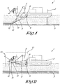
Figure 1 schematically shows a side view of a cutter-suction dredger according to the invention in a first operating situation; -
figure 2 shows the cutter-suction dredger offigure 2 in a second operating situation; -
figure 3 shows the part of the cutter-suction dredger offigure 2 indicated by F3 on a larger scale; -
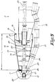
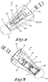
figures 4 and 5 schematically show a perspective top view and bottom view respectively of an extension piece according to the invention;
and -
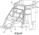
figure 6 shows a perspective view of the part of the cutter-suction dredger offigure 2 indicated by F6 on a larger scale. - The cutter-suction dredger 1, or cutter-suction dredge, shown in
figures 1 to 3 is a ship that is provided with aspud 2 near its front, acutting arm 3, or ladder, on its underside and awork platform 4 on its back. - The
cutting arm 3 can be raised and lowered again by means of alifting device 5. In the operating situation offigure 1 , in which thecutting arm 3 is lowered and used for loosening bed material from ahard seabed 7, thespud 2 is anchored in theseabed 7 to be able to apply sufficient force to the cutting arm to be able to effectively loosen material from theseabed 7. - In the operating situation of
figure 2 , in which the cutting arm is raised and not actively used for loosening bed material, the spud is not necessary and is stored horizontally on the cutter-suction dredger 1. - The cutter-suction dredger 1 is provided with two possible suspension points for the
cutting arm 3, i.e. atop suspension point 8 and abottom suspension point 9. In the drawings thecutting arm 3 is suspended from thebottom suspension point 9. - The
cutting arm 9 is provided with anextension piece 10. Acutting head 12 is affixed at afirst end 11, more specifically the free end, of theextension piece 10. Asuction pipe 13 runs from thecutting head 12 for the transport of loosened bed material to the hull of the cutter-suction dredger. - Although a
cutting arm 3 with anextension piece 10 is of course still a cutting arm, for completeness in this description the term cutting arm is used for the originalunextended cutting arm 3, and the combination ofcutting arm 3 andextension piece 10 is denoted an extended cutting arm. - The
extension piece 10 essentially consists of asteel casing 14 in two parts that are connected bypartitions 15 that are provided with a cutaway that is oriented towards the top of theextension piece 10. The length L of the casing is approximately 10 metres. - The
extension piece 10 is provided with aninternal flange 17 at itssecond end 16. Thecutting arm 3 is provided with anexternal flange 19 close to itsfree end 18. These twoflanges extension piece 10 and thecutting arm 3 together. - A
multipart driveshaft 20 for the drive of thecutting head 12 is provided through thecutting arm 3 and theextension piece 10. - In the
cutting arm 3 thisdriveshaft 20 is formed by the original driveshaft. This is mounted on bearings at thefree end 18 of thecutting arm 3 and is provided with acoupling 21 for fasting acutting head 12 thereto. - In the
extension piece 10 thedriveshaft 20 is formed from three parts, i.e. afirst part 22 at thesecond end 16, asecond part 23 at thefirst end 11, and athird part 24. - The
first part 22 is constructed as acoupling 25, as is usually present at acutting head 12, and is affixed, more specifically screwed, to thecomplementary coupling 21 of the driveshaft of the cutting arm. At its other end thefirst part 22 is provided with a flange. - The
second part 23 is mounted on bearings close to thefirst end 11 of theextension piece 10, and protrudes partially outside thecasing 14, where it is provided with acoupling 21 for acutting head 12, and in the drawings shown also with thiscutting head 12. At its other end thesecond part 23 is provided with a flange. - The
third part 24 is a cylindrical shaft part that is provided with a flange at both ends. - The
third part 24 is affixed between thefirst part 22 and thesecond part 23, whereby the flanges of the saidparts - An
inlet piece 26 for asuction pipe 13 is fastened to theextension piece 10, as well as apartial suction pipe 13 that is coupled to thesuction pipe 13 of thecutting arm 3. -
Figures 4 and 5 show anunmounted extension piece 10. Thisextension piece 10 is already provided with acutting head 12. - The
work platform 4 at the back of the cutter-suction dredger is shown in more detail infigures 6 and 7. It essentially consists of a supportingconstruction 27 fastened to the cutter-suction dredger on which guide rails 28 are mounted. - The
U-shaped work platform 4 is mounted on these guide rails 28. Thanks to the guide rails 28 thework platform 4 can be moved upwards and downwards, whereby it has two working positions in which it can be fastened so that it can be entered safely. - The first, highest, working position is shown in
figure 6 . This working position is at such a height and such a distance from the suspension points 8,9 of the cutting arm that the cuttinghead 12, if mounted, on a raisedunextended cutting arm 23 that is suspended from thetop suspension point 8, is accessible from thework platform 4 at this working position. - The second, lowest, working position that is not shown in
figure 6 is at such a height and such a distance from the suspension points 8, 9 of the cuttingarm 3 that the cuttinghead 12, if mounted, on a raisedunextended cutting arm 3 that is suspended from thebottom suspension point 9, is accessible from this working position. - Although the
cutting arm 3 with theextension piece 10 of the cutter-suction dredger 1 described is suspended from thebottom suspension point 9, thework platform 4 is set at its highest working position. Hereby thework platform 4 is provided with a U-shapedauxiliary platform 29 that is fastened to thework platform 4 but which is lower and further to the back, so that the cuttinghead 12 on theextension piece 10 is accessible from theauxiliary platform 29 for maintenance, in particular for the replacement of the cutting teeth of the cuttinghead 12. - The manufacture and operation of a cutter-suction dredger 1 according to the invention is simple and as follows.
- A cutter-suction dredger 1 without extension piece, that is intended to be able to operate up to a certain water depth, is modified to this end.
- First the cutting
arm 3 of the cutter-suction dredger 1 is fastened to thelowest suspension point 9 provided to this end. Then the cuttinghead 12 is detached from the cutting arm and temporarily set to one side. - The cutting
arm 3 is now provided with aflange 19. - An
extension piece 10 manufactured beforehand is mounted by itsflange 17 on theflange 19 of the cuttingarm 3. - Then the
first part 22 of thedriveshaft 20 of theextension piece 10 is mounted on thecutting arm 3, more specifically on thecoupling 21 for the cuttinghead 12. Thesecond part 23 of thisdriveshaft 20 is hereby already present in thefirst end 11 of theextension piece 10. - Then the
third part 24 of thedriveshaft 20 of theextension piece 10 is slid between thefirst part 22 and thesecond part 23 of thisdriveshaft 20 and fastened to thefirst part 22 andsecond part 23 by means of the flanges present on the parts. - As is clear from
figure 4 there is sufficient space for these assembly activities thanks to the cutaway in thepartitions 15. - Then the cutting
head 12 is again affixed to thesecond part 23 of thedriveshaft 20. The cuttinghead 12 can of course be affixed to theextension piece 10 earlier. - The cutter-suction dredger 1 is now suitable for operation seven metres deeper below the water surface than previously.
- To this end the
spud 2 is lowered and secured in theseabed 7. The cuttingarm 3 is also lowered. The cuttingarm 3 can now loosen material from theseabed 7, whereby this material is immediately sucked up by thesuction pipe 13 to the hull of the cutter-suction dredger 1. The necessary counter pressure for the cuttinghead 12 is hereby provided by thespud 2. - From the hull of the cutter-suction dredger 1 the material is removed via a pipe or pumped over to other ships and hereby removed.
- When removing bed material the cutter-suction dredger 1 makes a turning movement around the
spud 2, so that a circular track of material is removed from theseabed 7. Then thanks to a movable carriage in the cutter-suction dredger 1, to which the spud is fastened, the cutter-suction dredger 1 moves a small distance backwards with respect to thespud 2, after which a new circular track of material is removed from theseabed 7. - When the cutting elements on the cutting
head 12 have to be replaced or when for another reason access is required to the cuttinghead 12, it is raised, thework platform 4 is placed in its highest working position and the desired access can be obtained via theauxiliary platform 29. - The present invention is by no means limited to the embodiments described as an example and shown in the drawings, but an extension piece and a cutter-suction dredger according to the invention can be realised in all kinds of forms and dimensions without departing from the scope of the invention as defined in the appended claims.
Claims (11)
- Extension piece (10) for extending a raisable and lowerable cutting arm (3) of a cutter-suction dredger (1) for cutting material loose from the bed (7) of a body of water, whereby this cutting arm (3) comprises a first driveshaft (20) for driving a cutting head (12), whereby the extension piece (10) has a first end (11) for detachably mounting the cutting head (12) and a second end (16) for detachably coupling to a free end (18) of the cutting arm (3), whereby the extension piece (10) is provided with a second driveshaft (20) for driving the cutting head (12) that is arranged to be detachably coupled to the first driveshaft (20) in the cutting arm (3), whereby the extension piece (10) is constructed as a steel structure that is provided with a flange (17) for coupling to the cutting arm (3).
- Extension piece according to claim 1, characterised in that it is intended for a cutting arm (3) that is provided with a suction pipe (13) for loosened material, whereby the extension piece (10) also comprises an inlet piece (26) for a suction pipe (13).
- Extension piece according to any one of the previous claims, characterised in that the driveshaft (20) in the extension piece (10) comprises at least three arts, i.e. a first part (22) that is oriented to be affixed on the driveshaft (20) of the cutting arm (3), a second part (23) that is mounted on bearings at the first end (11) of the extension piece (10) and a third part (24) to detachably connect both first and second parts (22,23).
- Extension piece according to claim 3, characterised in that the third part (24) can be coupled to the first part (22) and to the second part (23) by the first part (22) and the second part (23) both being provided at an end with a flange and the third part (24) being provided with a complementary flange at both its ends.
- Extension piece according to any one of the previous claims, characterised in that it has a length (L) that is greater than 3 metres.
- Extension piece according to any one of the previous claims, characterised in that it has a length (L) that is less than 15 metres.
- Cutter-suction dredger (1) with a raisable and lowerable cutting arm (3) for cutting material loose from the bed (7) of a body of water, whereby the cutting arm (3) is provided with an extension piece (10) according to any one of the previous claims 1 to 6.
- Cutter-suction dredger according to claim 7, characterised in that both the extension piece (10) and the cutting arm (3) are provided with a flange (17, 19) to be able to reversibly couple the two together.
- Cutter-suction dredger according to claim 7 or 8, characterised in that it is provided with two suspension points (8,9) at different heights for the cutting arm (3) and a work platform (4) at its back to gain access to the free end (18) of the cutting arm (3) in the raised position without an extension piece (10), whereby the work platform (4) can be moved between two working positions at different heights, whereby the lowest working position is suitable for gaining the said access when the cutting arm (3) is suspended from the lowest suspension point (9) and the highest working position is suitable for gaining the said access when the cutting arm (3) is suspended from the highest suspension point (8), whereby the work platform (4) is provided with an auxiliary platform (29) that is lower than the work platform (4) and which protrudes backwards from the work platform (4), and that, with the work platform (4) in the highest working position, has such a position that access is gained to the first end (11) of the extension piece (10) from the auxiliary platform (29) when the cutting arm (3) is suspended from the lowest suspension point (9).
- Method for loosening a bed (7) of a body of water up to a specific depth below the water surface, characterised in that a cutter-suction dredger (1) with a raisable and lowerable cutting arm (3) is used that is designed to operate up to a depth that is less than the specific depth, whereby the cutting arm (3) is provided with an extension piece (10) according to any one of the claims 1 to 6, and whereby the bed (7) is loosened by means of a cutting head (12) on the first end (11) of the extension piece (10).
- Method according to claim 10, characterised in that the cutter-suction dredger (1) that is used for loosening the bed (7) is a cutter-suction dredger (1) according to claim 9, whereby the cutting arm (3) is suspended from the lowest suspension point (9) and whereby, when the cutting head (12) requires maintenance or must be entirely or partially replaced, the auxiliary platform (29) is used to gain access to the cutting head (12), whereby the work platform (4) is at its highest working position.
Priority Applications (2)
| Application Number | Priority Date | Filing Date | Title |
|---|---|---|---|
| PL14003699T PL2871291T3 (en) | 2013-11-05 | 2014-11-03 | Extension piece for a cutting arm of a cutter-suction dredger and method for loosening the bed of a body of water |
| HRP20181131TT HRP20181131T1 (en) | 2013-11-05 | 2018-07-19 | Extension piece for a cutting arm of a cutter-suction dredger and method for loosening the bed of a body of water |
Applications Claiming Priority (1)
| Application Number | Priority Date | Filing Date | Title |
|---|---|---|---|
| BE2013/0750A BE1021787B1 (en) | 2013-11-05 | 2013-11-05 | EXTENSION FOR A CUTTER PISTON CUTTER ARM, CUTTER PISTON AND PROCESS TO DISCHARGE A BOTTOM OF A WATER MASS |
Publications (3)
| Publication Number | Publication Date |
|---|---|
| EP2871291A2 EP2871291A2 (en) | 2015-05-13 |
| EP2871291A3 EP2871291A3 (en) | 2015-05-20 |
| EP2871291B1 true EP2871291B1 (en) | 2018-06-27 |
Family
ID=49916751
Family Applications (1)
| Application Number | Title | Priority Date | Filing Date |
|---|---|---|---|
| EP14003699.7A Active EP2871291B1 (en) | 2013-11-05 | 2014-11-03 | Extension piece for a cutting arm of a cutter-suction dredger and method for loosening the bed of a body of water |
Country Status (8)
| Country | Link |
|---|---|
| EP (1) | EP2871291B1 (en) |
| BE (1) | BE1021787B1 (en) |
| CY (1) | CY1120965T1 (en) |
| DK (1) | DK2871291T3 (en) |
| ES (1) | ES2687261T3 (en) |
| HR (1) | HRP20181131T1 (en) |
| PL (1) | PL2871291T3 (en) |
| PT (1) | PT2871291T (en) |
Families Citing this family (1)
| Publication number | Priority date | Publication date | Assignee | Title |
|---|---|---|---|---|
| CN113175016A (en) * | 2021-04-26 | 2021-07-27 | 江苏省水利机械制造有限公司 | Composite underwater power dredging drag harrow |
Family Cites Families (4)
| Publication number | Priority date | Publication date | Assignee | Title |
|---|---|---|---|---|
| US2242520A (en) * | 1937-09-09 | 1941-05-20 | Grundborg Olaf | Hydraulic mining apparatus |
| NL129899C (en) * | 1968-03-12 | |||
| DE2051941A1 (en) * | 1969-11-05 | 1971-05-13 | Dan Ionescu Sisesti, Bukarest | Floating suction dredger with movable suction pipe |
| NL156204B (en) * | 1973-08-01 | 1978-03-15 | Bos Kalis Westminster | DEVICE FOR DROWING AT VARIABLE DEPTH. |
-
2013
- 2013-11-05 BE BE2013/0750A patent/BE1021787B1/en active
-
2014
- 2014-11-03 ES ES14003699.7T patent/ES2687261T3/en active Active
- 2014-11-03 PT PT14003699T patent/PT2871291T/en unknown
- 2014-11-03 EP EP14003699.7A patent/EP2871291B1/en active Active
- 2014-11-03 PL PL14003699T patent/PL2871291T3/en unknown
- 2014-11-03 DK DK14003699.7T patent/DK2871291T3/en active
-
2018
- 2018-07-19 HR HRP20181131TT patent/HRP20181131T1/en unknown
- 2018-09-07 CY CY181100937T patent/CY1120965T1/en unknown
Non-Patent Citations (1)
| Title |
|---|
| None * |
Also Published As
| Publication number | Publication date |
|---|---|
| CY1120965T1 (en) | 2019-12-11 |
| HRP20181131T1 (en) | 2018-10-05 |
| EP2871291A3 (en) | 2015-05-20 |
| EP2871291A2 (en) | 2015-05-13 |
| BE1021787B1 (en) | 2016-01-18 |
| PT2871291T (en) | 2018-10-16 |
| PL2871291T3 (en) | 2019-07-31 |
| DK2871291T3 (en) | 2018-09-24 |
| ES2687261T3 (en) | 2018-10-24 |
Similar Documents
| Publication | Publication Date | Title |
|---|---|---|
| CN210761170U (en) | Positioning pile device for ship | |
| JP5119346B2 (en) | Lifting thruster | |
| CN106574453A (en) | Method of and system for installing foundation elements in an underwater ground formation | |
| WO2013157944A1 (en) | Cutter suction dredger | |
| CN106381870B (en) | A kind of deep concrete mixture ship pile frame system and pile making method | |
| KR100932971B1 (en) | Detachable and movable workbench lifting work barge | |
| US20150086389A1 (en) | Pumping system | |
| EP2871291A2 (en) | Extension piece for a cutting arm of a cutter-suction dredger and method for loosening the bed of a body of water | |
| CN213625592U (en) | Lifting, placing and anchoring device for leveling frame in riprap leveling ship | |
| US9988789B2 (en) | Earth removal and sand mining system and method | |
| US10287746B1 (en) | Wide-format swinging ladder dredge | |
| EP1893820B1 (en) | Device and method for changing a suction mouth | |
| TWI658188B (en) | Sludge removal device | |
| JP2020094335A (en) | Drain material placing ship | |
| CN106628000A (en) | Steel pile positioning trolley | |
| US4624066A (en) | Dredge with twin cutter head and suspension therefor | |
| JP2012077566A (en) | Pneumatic caisson earth removal system | |
| CN205654585U (en) | Liftable latent water pump system who adjusts | |
| JPH0619642Y2 (en) | Sea garden building equipment | |
| CN212427351U (en) | Floating dock type pump station | |
| CN215906874U (en) | Underwater foundation bed leveling device | |
| CN204645124U (en) | Crane span structure lifting A font framework | |
| CN212561658U (en) | Cutter suction dredger steel pile trolley lifting device | |
| CN216861762U (en) | Buoyancy tank device for towing of lifting type net cage | |
| CN222500243U (en) | Constant-tension continuous pile punching system |
Legal Events
| Date | Code | Title | Description |
|---|---|---|---|
| PUAL | Search report despatched |
Free format text: ORIGINAL CODE: 0009013 |
|
| PUAI | Public reference made under article 153(3) epc to a published international application that has entered the european phase |
Free format text: ORIGINAL CODE: 0009012 |
|
| 17P | Request for examination filed |
Effective date: 20141103 |
|
| AK | Designated contracting states |
Kind code of ref document: A2 Designated state(s): AL AT BE BG CH CY CZ DE DK EE ES FI FR GB GR HR HU IE IS IT LI LT LU LV MC MK MT NL NO PL PT RO RS SE SI SK SM TR |
|
| AX | Request for extension of the european patent |
Extension state: BA ME |
|
| AK | Designated contracting states |
Kind code of ref document: A3 Designated state(s): AL AT BE BG CH CY CZ DE DK EE ES FI FR GB GR HR HU IE IS IT LI LT LU LV MC MK MT NL NO PL PT RO RS SE SI SK SM TR |
|
| AX | Request for extension of the european patent |
Extension state: BA ME |
|
| RIC1 | Information provided on ipc code assigned before grant |
Ipc: E02F 3/92 20060101ALI20150415BHEP Ipc: E02F 3/90 20060101ALI20150415BHEP Ipc: E02F 3/88 20060101AFI20150415BHEP |
|
| RAP1 | Party data changed (applicant data changed or rights of an application transferred) |
Owner name: JAN DE NUL, NAAMLOZE VENNOOTSCHAP |
|
| R17P | Request for examination filed (corrected) |
Effective date: 20151105 |
|
| RBV | Designated contracting states (corrected) |
Designated state(s): AL AT BE BG CH CY CZ DE DK EE ES FI FR GB GR HR HU IE IS IT LI LT LU LV MC MK MT NL NO PL PT RO RS SE SI SK SM TR |
|
| RAP1 | Party data changed (applicant data changed or rights of an application transferred) |
Owner name: JAN DE NUL N.V. |
|
| GRAP | Despatch of communication of intention to grant a patent |
Free format text: ORIGINAL CODE: EPIDOSNIGR1 |
|
| STAA | Information on the status of an ep patent application or granted ep patent |
Free format text: STATUS: GRANT OF PATENT IS INTENDED |
|
| INTG | Intention to grant announced |
Effective date: 20180416 |
|
| GRAS | Grant fee paid |
Free format text: ORIGINAL CODE: EPIDOSNIGR3 |
|
| GRAA | (expected) grant |
Free format text: ORIGINAL CODE: 0009210 |
|
| STAA | Information on the status of an ep patent application or granted ep patent |
Free format text: STATUS: THE PATENT HAS BEEN GRANTED |
|
| AK | Designated contracting states |
Kind code of ref document: B1 Designated state(s): AL AT BE BG CH CY CZ DE DK EE ES FI FR GB GR HR HU IE IS IT LI LT LU LV MC MK MT NL NO PL PT RO RS SE SI SK SM TR |
|
| REG | Reference to a national code |
Ref country code: GB Ref legal event code: FG4D |
|
| REG | Reference to a national code |
Ref country code: AT Ref legal event code: REF Ref document number: 1012487 Country of ref document: AT Kind code of ref document: T Effective date: 20180715 |
|
| REG | Reference to a national code |
Ref country code: HR Ref legal event code: TUEP Ref document number: P20181131 Country of ref document: HR |
|
| REG | Reference to a national code |
Ref country code: IE Ref legal event code: FG4D |
|
| REG | Reference to a national code |
Ref country code: DE Ref legal event code: R096 Ref document number: 602014027435 Country of ref document: DE |
|
| REG | Reference to a national code |
Ref country code: NL Ref legal event code: FP |
|
| REG | Reference to a national code |
Ref country code: RO Ref legal event code: EPE Ref country code: SE Ref legal event code: TRGR |
|
| REG | Reference to a national code |
Ref country code: HR Ref legal event code: ULIC Ref document number: P20181131 Country of ref document: HR Name of requester: DREDGING AND MARITIME MANAGEMENT SA, LU |
|
| REG | Reference to a national code |
Ref country code: DK Ref legal event code: T3 Effective date: 20180919 |
|
| REG | Reference to a national code |
Ref country code: FR Ref legal event code: PLFP Year of fee payment: 5 |
|
| REG | Reference to a national code |
Ref country code: HR Ref legal event code: T1PR Ref document number: P20181131 Country of ref document: HR |
|
| REG | Reference to a national code |
Ref country code: PT Ref legal event code: SC4A Ref document number: 2871291 Country of ref document: PT Date of ref document: 20181016 Kind code of ref document: T Free format text: AVAILABILITY OF NATIONAL TRANSLATION Effective date: 20180917 |
|
| REG | Reference to a national code |
Ref country code: ES Ref legal event code: FG2A Ref document number: 2687261 Country of ref document: ES Kind code of ref document: T3 Effective date: 20181024 |
|
| REG | Reference to a national code |
Ref country code: NO Ref legal event code: T2 Effective date: 20180627 |
|
| PG25 | Lapsed in a contracting state [announced via postgrant information from national office to epo] |
Ref country code: LT Free format text: LAPSE BECAUSE OF FAILURE TO SUBMIT A TRANSLATION OF THE DESCRIPTION OR TO PAY THE FEE WITHIN THE PRESCRIBED TIME-LIMIT Effective date: 20180627 Ref country code: BG Free format text: LAPSE BECAUSE OF FAILURE TO SUBMIT A TRANSLATION OF THE DESCRIPTION OR TO PAY THE FEE WITHIN THE PRESCRIBED TIME-LIMIT Effective date: 20180927 |
|
| REG | Reference to a national code |
Ref country code: LT Ref legal event code: MG4D |
|
| PG25 | Lapsed in a contracting state [announced via postgrant information from national office to epo] |
Ref country code: LV Free format text: LAPSE BECAUSE OF FAILURE TO SUBMIT A TRANSLATION OF THE DESCRIPTION OR TO PAY THE FEE WITHIN THE PRESCRIBED TIME-LIMIT Effective date: 20180627 Ref country code: RS Free format text: LAPSE BECAUSE OF FAILURE TO SUBMIT A TRANSLATION OF THE DESCRIPTION OR TO PAY THE FEE WITHIN THE PRESCRIBED TIME-LIMIT Effective date: 20180627 |
|
| REG | Reference to a national code |
Ref country code: AT Ref legal event code: MK05 Ref document number: 1012487 Country of ref document: AT Kind code of ref document: T Effective date: 20180627 |
|
| PG25 | Lapsed in a contracting state [announced via postgrant information from national office to epo] |
Ref country code: SK Free format text: LAPSE BECAUSE OF FAILURE TO SUBMIT A TRANSLATION OF THE DESCRIPTION OR TO PAY THE FEE WITHIN THE PRESCRIBED TIME-LIMIT Effective date: 20180627 Ref country code: CZ Free format text: LAPSE BECAUSE OF FAILURE TO SUBMIT A TRANSLATION OF THE DESCRIPTION OR TO PAY THE FEE WITHIN THE PRESCRIBED TIME-LIMIT Effective date: 20180627 Ref country code: AT Free format text: LAPSE BECAUSE OF FAILURE TO SUBMIT A TRANSLATION OF THE DESCRIPTION OR TO PAY THE FEE WITHIN THE PRESCRIBED TIME-LIMIT Effective date: 20180627 Ref country code: EE Free format text: LAPSE BECAUSE OF FAILURE TO SUBMIT A TRANSLATION OF THE DESCRIPTION OR TO PAY THE FEE WITHIN THE PRESCRIBED TIME-LIMIT Effective date: 20180627 |
|
| PG25 | Lapsed in a contracting state [announced via postgrant information from national office to epo] |
Ref country code: SM Free format text: LAPSE BECAUSE OF FAILURE TO SUBMIT A TRANSLATION OF THE DESCRIPTION OR TO PAY THE FEE WITHIN THE PRESCRIBED TIME-LIMIT Effective date: 20180627 |
|
| REG | Reference to a national code |
Ref country code: GR Ref legal event code: EP Ref document number: 20180402689 Country of ref document: GR Effective date: 20190225 |
|
| REG | Reference to a national code |
Ref country code: DE Ref legal event code: R097 Ref document number: 602014027435 Country of ref document: DE |
|
| PLBE | No opposition filed within time limit |
Free format text: ORIGINAL CODE: 0009261 |
|
| STAA | Information on the status of an ep patent application or granted ep patent |
Free format text: STATUS: NO OPPOSITION FILED WITHIN TIME LIMIT |
|
| 26N | No opposition filed |
Effective date: 20190328 |
|
| REG | Reference to a national code |
Ref country code: CH Ref legal event code: PL |
|
| PG25 | Lapsed in a contracting state [announced via postgrant information from national office to epo] |
Ref country code: SI Free format text: LAPSE BECAUSE OF FAILURE TO SUBMIT A TRANSLATION OF THE DESCRIPTION OR TO PAY THE FEE WITHIN THE PRESCRIBED TIME-LIMIT Effective date: 20180627 Ref country code: CH Free format text: LAPSE BECAUSE OF NON-PAYMENT OF DUE FEES Effective date: 20181130 Ref country code: LI Free format text: LAPSE BECAUSE OF NON-PAYMENT OF DUE FEES Effective date: 20181130 |
|
| REG | Reference to a national code |
Ref country code: HR Ref legal event code: ODRP Ref document number: P20181131 Country of ref document: HR Payment date: 20191024 Year of fee payment: 6 |
|
| PG25 | Lapsed in a contracting state [announced via postgrant information from national office to epo] |
Ref country code: AL Free format text: LAPSE BECAUSE OF FAILURE TO SUBMIT A TRANSLATION OF THE DESCRIPTION OR TO PAY THE FEE WITHIN THE PRESCRIBED TIME-LIMIT Effective date: 20180627 |
|
| PG25 | Lapsed in a contracting state [announced via postgrant information from national office to epo] |
Ref country code: HU Free format text: LAPSE BECAUSE OF FAILURE TO SUBMIT A TRANSLATION OF THE DESCRIPTION OR TO PAY THE FEE WITHIN THE PRESCRIBED TIME-LIMIT; INVALID AB INITIO Effective date: 20141103 Ref country code: MK Free format text: LAPSE BECAUSE OF NON-PAYMENT OF DUE FEES Effective date: 20180627 |
|
| REG | Reference to a national code |
Ref country code: HR Ref legal event code: ODRP Ref document number: P20181131 Country of ref document: HR Payment date: 20210107 Year of fee payment: 7 |
|
| REG | Reference to a national code |
Ref country code: HR Ref legal event code: ODRP Ref document number: P20181131 Country of ref document: HR Payment date: 20211015 Year of fee payment: 8 |
|
| PG25 | Lapsed in a contracting state [announced via postgrant information from national office to epo] |
Ref country code: CY Free format text: LAPSE BECAUSE OF NON-PAYMENT OF DUE FEES Effective date: 20211103 |
|
| REG | Reference to a national code |
Ref country code: HR Ref legal event code: ODRP Ref document number: P20181131 Country of ref document: HR Payment date: 20221019 Year of fee payment: 9 |
|
| REG | Reference to a national code |
Ref country code: HR Ref legal event code: ODRP Ref document number: P20181131 Country of ref document: HR Payment date: 20231016 Year of fee payment: 10 |
|
| REG | Reference to a national code |
Ref country code: HR Ref legal event code: ODRP Ref document number: P20181131 Country of ref document: HR Payment date: 20241015 Year of fee payment: 11 |
|
| PGFP | Annual fee paid to national office [announced via postgrant information from national office to epo] |
Ref country code: HR Payment date: 20250923 Year of fee payment: 12 |
|
| REG | Reference to a national code |
Ref country code: HR Ref legal event code: ODRP Ref document number: P20181131 Country of ref document: HR Payment date: 20250923 Year of fee payment: 12 |
|
| PGFP | Annual fee paid to national office [announced via postgrant information from national office to epo] |
Ref country code: NL Payment date: 20251015 Year of fee payment: 12 |
|
| PGFP | Annual fee paid to national office [announced via postgrant information from national office to epo] |
Ref country code: PT Payment date: 20251014 Year of fee payment: 12 |
|
| PGFP | Annual fee paid to national office [announced via postgrant information from national office to epo] |
Ref country code: LU Payment date: 20251124 Year of fee payment: 12 |
|
| PGFP | Annual fee paid to national office [announced via postgrant information from national office to epo] |
Ref country code: IS Payment date: 20251128 Year of fee payment: 12 Ref country code: DE Payment date: 20251126 Year of fee payment: 12 |
|
| PGFP | Annual fee paid to national office [announced via postgrant information from national office to epo] |
Ref country code: GB Payment date: 20251125 Year of fee payment: 12 |
|
| PGFP | Annual fee paid to national office [announced via postgrant information from national office to epo] |
Ref country code: NO Payment date: 20251120 Year of fee payment: 12 Ref country code: MC Payment date: 20251120 Year of fee payment: 12 |
|
| PGFP | Annual fee paid to national office [announced via postgrant information from national office to epo] |
Ref country code: IT Payment date: 20251121 Year of fee payment: 12 Ref country code: FI Payment date: 20251124 Year of fee payment: 12 Ref country code: DK Payment date: 20251124 Year of fee payment: 12 |
|
| PGFP | Annual fee paid to national office [announced via postgrant information from national office to epo] |
Ref country code: FR Payment date: 20251015 Year of fee payment: 12 |
|
| PGFP | Annual fee paid to national office [announced via postgrant information from national office to epo] |
Ref country code: BE Payment date: 20251015 Year of fee payment: 12 Ref country code: TR Payment date: 20251014 Year of fee payment: 12 Ref country code: GR Payment date: 20251118 Year of fee payment: 12 |
|
| PGFP | Annual fee paid to national office [announced via postgrant information from national office to epo] |
Ref country code: SE Payment date: 20251124 Year of fee payment: 12 |
|
| PGFP | Annual fee paid to national office [announced via postgrant information from national office to epo] |
Ref country code: IE Payment date: 20251118 Year of fee payment: 12 Ref country code: CY Payment date: 20251014 Year of fee payment: 12 |
|
| PGFP | Annual fee paid to national office [announced via postgrant information from national office to epo] |
Ref country code: MT Payment date: 20251125 Year of fee payment: 12 |
|
| PGFP | Annual fee paid to national office [announced via postgrant information from national office to epo] |
Ref country code: PL Payment date: 20251008 Year of fee payment: 12 |
|
| PGFP | Annual fee paid to national office [announced via postgrant information from national office to epo] |
Ref country code: RO Payment date: 20251023 Year of fee payment: 12 |
|
| PGFP | Annual fee paid to national office [announced via postgrant information from national office to epo] |
Ref country code: ES Payment date: 20251209 Year of fee payment: 12 |