EP2871262A1 - Structure with embedded pipe and manufacturing method therefor - Google Patents
Structure with embedded pipe and manufacturing method therefor Download PDFInfo
- Publication number
- EP2871262A1 EP2871262A1 EP20130813481 EP13813481A EP2871262A1 EP 2871262 A1 EP2871262 A1 EP 2871262A1 EP 20130813481 EP20130813481 EP 20130813481 EP 13813481 A EP13813481 A EP 13813481A EP 2871262 A1 EP2871262 A1 EP 2871262A1
- Authority
- EP
- European Patent Office
- Prior art keywords
- pipe
- base material
- alloy
- powder
- recessed portion
- Prior art date
- Legal status (The legal status is an assumption and is not a legal conclusion. Google has not performed a legal analysis and makes no representation as to the accuracy of the status listed.)
- Withdrawn
Links
- 238000004519 manufacturing process Methods 0.000 title claims abstract description 14
- 239000000463 material Substances 0.000 claims abstract description 74
- 239000000843 powder Substances 0.000 claims abstract description 51
- 229910052751 metal Inorganic materials 0.000 claims abstract description 40
- 239000002184 metal Substances 0.000 claims abstract description 40
- 229910045601 alloy Inorganic materials 0.000 claims abstract description 22
- 239000000956 alloy Substances 0.000 claims abstract description 22
- 239000007790 solid phase Substances 0.000 claims abstract description 9
- 238000000034 method Methods 0.000 claims description 23
- 229910000881 Cu alloy Inorganic materials 0.000 claims description 10
- 229910052782 aluminium Inorganic materials 0.000 claims description 9
- XAGFODPZIPBFFR-UHFFFAOYSA-N aluminium Chemical compound [Al] XAGFODPZIPBFFR-UHFFFAOYSA-N 0.000 claims description 9
- RYGMFSIKBFXOCR-UHFFFAOYSA-N Copper Chemical compound [Cu] RYGMFSIKBFXOCR-UHFFFAOYSA-N 0.000 claims description 8
- 229910000838 Al alloy Inorganic materials 0.000 claims description 6
- 229910052802 copper Inorganic materials 0.000 claims description 6
- 239000010949 copper Substances 0.000 claims description 6
- 238000000151 deposition Methods 0.000 claims description 4
- 238000005507 spraying Methods 0.000 claims description 4
- 239000010935 stainless steel Substances 0.000 claims description 4
- 229910001220 stainless steel Inorganic materials 0.000 claims description 4
- 229910000990 Ni alloy Inorganic materials 0.000 claims description 3
- RTAQQCXQSZGOHL-UHFFFAOYSA-N Titanium Chemical compound [Ti] RTAQQCXQSZGOHL-UHFFFAOYSA-N 0.000 claims description 3
- 229910052758 niobium Inorganic materials 0.000 claims description 3
- 239000010955 niobium Substances 0.000 claims description 3
- GUCVJGMIXFAOAE-UHFFFAOYSA-N niobium atom Chemical compound [Nb] GUCVJGMIXFAOAE-UHFFFAOYSA-N 0.000 claims description 3
- 229910052715 tantalum Inorganic materials 0.000 claims description 3
- GUVRBAGPIYLISA-UHFFFAOYSA-N tantalum atom Chemical compound [Ta] GUVRBAGPIYLISA-UHFFFAOYSA-N 0.000 claims description 3
- 239000010936 titanium Substances 0.000 claims description 3
- 229910052719 titanium Inorganic materials 0.000 claims description 3
- 230000001070 adhesive effect Effects 0.000 abstract description 7
- 239000007789 gas Substances 0.000 description 30
- 239000007921 spray Substances 0.000 description 25
- 239000011248 coating agent Substances 0.000 description 14
- 238000000576 coating method Methods 0.000 description 14
- 230000000052 comparative effect Effects 0.000 description 14
- 238000010586 diagram Methods 0.000 description 9
- 239000012530 fluid Substances 0.000 description 7
- 230000003287 optical effect Effects 0.000 description 6
- 230000002349 favourable effect Effects 0.000 description 5
- 238000001878 scanning electron micrograph Methods 0.000 description 5
- 239000013590 bulk material Substances 0.000 description 3
- 239000000498 cooling water Substances 0.000 description 3
- 238000005260 corrosion Methods 0.000 description 3
- 230000007797 corrosion Effects 0.000 description 3
- 238000005336 cracking Methods 0.000 description 3
- IJGRMHOSHXDMSA-UHFFFAOYSA-N Atomic nitrogen Chemical compound N#N IJGRMHOSHXDMSA-UHFFFAOYSA-N 0.000 description 2
- 239000000853 adhesive Substances 0.000 description 2
- 238000005553 drilling Methods 0.000 description 2
- 230000000694 effects Effects 0.000 description 2
- 238000010438 heat treatment Methods 0.000 description 2
- 239000007788 liquid Substances 0.000 description 2
- 239000002245 particle Substances 0.000 description 2
- 239000000758 substrate Substances 0.000 description 2
- 0 *N=C1CCCC1 Chemical compound *N=C1CCCC1 0.000 description 1
- QVGXLLKOCUKJST-UHFFFAOYSA-N atomic oxygen Chemical compound [O] QVGXLLKOCUKJST-UHFFFAOYSA-N 0.000 description 1
- 230000015572 biosynthetic process Effects 0.000 description 1
- 239000000470 constituent Substances 0.000 description 1
- 239000002826 coolant Substances 0.000 description 1
- 239000000112 cooling gas Substances 0.000 description 1
- 238000005520 cutting process Methods 0.000 description 1
- 238000005516 engineering process Methods 0.000 description 1
- 238000002474 experimental method Methods 0.000 description 1
- 239000001307 helium Substances 0.000 description 1
- 229910052734 helium Inorganic materials 0.000 description 1
- SWQJXJOGLNCZEY-UHFFFAOYSA-N helium atom Chemical compound [He] SWQJXJOGLNCZEY-UHFFFAOYSA-N 0.000 description 1
- 239000011261 inert gas Substances 0.000 description 1
- 239000004973 liquid crystal related substance Substances 0.000 description 1
- 238000002844 melting Methods 0.000 description 1
- 230000008018 melting Effects 0.000 description 1
- 229910001092 metal group alloy Inorganic materials 0.000 description 1
- 238000003801 milling Methods 0.000 description 1
- 229910052757 nitrogen Inorganic materials 0.000 description 1
- 239000003960 organic solvent Substances 0.000 description 1
- 238000007254 oxidation reaction Methods 0.000 description 1
- 239000001301 oxygen Substances 0.000 description 1
- 229910052760 oxygen Inorganic materials 0.000 description 1
- 239000012071 phase Substances 0.000 description 1
- 230000000630 rising effect Effects 0.000 description 1
- 239000013535 sea water Substances 0.000 description 1
- 239000004065 semiconductor Substances 0.000 description 1
- 230000009466 transformation Effects 0.000 description 1
- XLYOFNOQVPJJNP-UHFFFAOYSA-N water Substances O XLYOFNOQVPJJNP-UHFFFAOYSA-N 0.000 description 1
Images




Classifications
-
- F—MECHANICAL ENGINEERING; LIGHTING; HEATING; WEAPONS; BLASTING
- F28—HEAT EXCHANGE IN GENERAL
- F28F—DETAILS OF HEAT-EXCHANGE AND HEAT-TRANSFER APPARATUS, OF GENERAL APPLICATION
- F28F3/00—Plate-like or laminated elements; Assemblies of plate-like or laminated elements
- F28F3/12—Elements constructed in the shape of a hollow panel, e.g. with channels
-
- C—CHEMISTRY; METALLURGY
- C23—COATING METALLIC MATERIAL; COATING MATERIAL WITH METALLIC MATERIAL; CHEMICAL SURFACE TREATMENT; DIFFUSION TREATMENT OF METALLIC MATERIAL; COATING BY VACUUM EVAPORATION, BY SPUTTERING, BY ION IMPLANTATION OR BY CHEMICAL VAPOUR DEPOSITION, IN GENERAL; INHIBITING CORROSION OF METALLIC MATERIAL OR INCRUSTATION IN GENERAL
- C23C—COATING METALLIC MATERIAL; COATING MATERIAL WITH METALLIC MATERIAL; SURFACE TREATMENT OF METALLIC MATERIAL BY DIFFUSION INTO THE SURFACE, BY CHEMICAL CONVERSION OR SUBSTITUTION; COATING BY VACUUM EVAPORATION, BY SPUTTERING, BY ION IMPLANTATION OR BY CHEMICAL VAPOUR DEPOSITION, IN GENERAL
- C23C24/00—Coating starting from inorganic powder
- C23C24/02—Coating starting from inorganic powder by application of pressure only
- C23C24/04—Impact or kinetic deposition of particles
-
- C—CHEMISTRY; METALLURGY
- C23—COATING METALLIC MATERIAL; COATING MATERIAL WITH METALLIC MATERIAL; CHEMICAL SURFACE TREATMENT; DIFFUSION TREATMENT OF METALLIC MATERIAL; COATING BY VACUUM EVAPORATION, BY SPUTTERING, BY ION IMPLANTATION OR BY CHEMICAL VAPOUR DEPOSITION, IN GENERAL; INHIBITING CORROSION OF METALLIC MATERIAL OR INCRUSTATION IN GENERAL
- C23C—COATING METALLIC MATERIAL; COATING MATERIAL WITH METALLIC MATERIAL; SURFACE TREATMENT OF METALLIC MATERIAL BY DIFFUSION INTO THE SURFACE, BY CHEMICAL CONVERSION OR SUBSTITUTION; COATING BY VACUUM EVAPORATION, BY SPUTTERING, BY ION IMPLANTATION OR BY CHEMICAL VAPOUR DEPOSITION, IN GENERAL
- C23C24/00—Coating starting from inorganic powder
- C23C24/08—Coating starting from inorganic powder by application of heat or pressure and heat
- C23C24/082—Coating starting from inorganic powder by application of heat or pressure and heat without intermediate formation of a liquid in the layer
- C23C24/085—Coating with metallic material, i.e. metals or metal alloys, optionally comprising hard particles, e.g. oxides, carbides or nitrides
- C23C24/087—Coating with metal alloys or metal elements only
-
- F—MECHANICAL ENGINEERING; LIGHTING; HEATING; WEAPONS; BLASTING
- F28—HEAT EXCHANGE IN GENERAL
- F28F—DETAILS OF HEAT-EXCHANGE AND HEAT-TRANSFER APPARATUS, OF GENERAL APPLICATION
- F28F1/00—Tubular elements; Assemblies of tubular elements
-
- F—MECHANICAL ENGINEERING; LIGHTING; HEATING; WEAPONS; BLASTING
- F28—HEAT EXCHANGE IN GENERAL
- F28F—DETAILS OF HEAT-EXCHANGE AND HEAT-TRANSFER APPARATUS, OF GENERAL APPLICATION
- F28F1/00—Tubular elements; Assemblies of tubular elements
- F28F1/10—Tubular elements and assemblies thereof with means for increasing heat-transfer area, e.g. with fins, with projections, with recesses
- F28F1/12—Tubular elements and assemblies thereof with means for increasing heat-transfer area, e.g. with fins, with projections, with recesses the means being only outside the tubular element
- F28F1/14—Tubular elements and assemblies thereof with means for increasing heat-transfer area, e.g. with fins, with projections, with recesses the means being only outside the tubular element and extending longitudinally
- F28F1/20—Tubular elements and assemblies thereof with means for increasing heat-transfer area, e.g. with fins, with projections, with recesses the means being only outside the tubular element and extending longitudinally the means being attachable to the element
-
- F—MECHANICAL ENGINEERING; LIGHTING; HEATING; WEAPONS; BLASTING
- F28—HEAT EXCHANGE IN GENERAL
- F28F—DETAILS OF HEAT-EXCHANGE AND HEAT-TRANSFER APPARATUS, OF GENERAL APPLICATION
- F28F7/00—Elements not covered by group F28F1/00, F28F3/00 or F28F5/00
- F28F7/02—Blocks traversed by passages for heat-exchange media
-
- F—MECHANICAL ENGINEERING; LIGHTING; HEATING; WEAPONS; BLASTING
- F28—HEAT EXCHANGE IN GENERAL
- F28D—HEAT-EXCHANGE APPARATUS, NOT PROVIDED FOR IN ANOTHER SUBCLASS, IN WHICH THE HEAT-EXCHANGE MEDIA DO NOT COME INTO DIRECT CONTACT
- F28D21/00—Heat-exchange apparatus not covered by any of the groups F28D1/00 - F28D20/00
- F28D2021/0019—Other heat exchangers for particular applications; Heat exchange systems not otherwise provided for
- F28D2021/0028—Other heat exchangers for particular applications; Heat exchange systems not otherwise provided for for cooling heat generating elements, e.g. for cooling electronic components or electric devices
- F28D2021/0029—Heat sinks
-
- F—MECHANICAL ENGINEERING; LIGHTING; HEATING; WEAPONS; BLASTING
- F28—HEAT EXCHANGE IN GENERAL
- F28F—DETAILS OF HEAT-EXCHANGE AND HEAT-TRANSFER APPARATUS, OF GENERAL APPLICATION
- F28F2255/00—Heat exchanger elements made of materials having special features or resulting from particular manufacturing processes
- F28F2255/14—Heat exchanger elements made of materials having special features or resulting from particular manufacturing processes molded
- F28F2255/146—Heat exchanger elements made of materials having special features or resulting from particular manufacturing processes molded overmolded
-
- F—MECHANICAL ENGINEERING; LIGHTING; HEATING; WEAPONS; BLASTING
- F28—HEAT EXCHANGE IN GENERAL
- F28F—DETAILS OF HEAT-EXCHANGE AND HEAT-TRANSFER APPARATUS, OF GENERAL APPLICATION
- F28F2275/00—Fastening; Joining
- F28F2275/02—Fastening; Joining by using bonding materials; by embedding elements in particular materials
Definitions
- the present invention relates to a pipe embedded structure in which a pipe is embedded in a metal member, the pipe circulating a temperature adjustment medium, such as a cooling gas or cooling water, and a method of manufacturing the pipe embedded structure.
- pipe embedded structures in which a pipe, which circulates a fluid is embedded in a metal member are used in various uses, such as a process of manufacturing products including semiconductors, liquid crystal display devices, and optical disks.
- a pipe embedded structure in which a heating medium (coolant) is circulated in the pipe is used as a temperature adjustment device (cold plate, or the like) that adjusts (cools or heats) the temperature of a substrate (for example, see Patent Literature 1).
- a pipe embedded structure in which a gas containing a predetermined constituent is circulated in a passage is sometimes used as a shower plate that supplies the gas to a substrate.
- Such pipe embedded structures are conventionally manufactured such that the pipe that circulates a fluid, and the metal member in which a recessed portion having a shape corresponding to the pipe is formed by drilling or the like are separately made, and the pipe is fitted into the recessed portion in the metal member.
- the present invention has been made in view of the foregoing, and an objective is to provide a pipe embedded structure with improved adhesive properties between a pipe that forms a passage and a metal member, and a method of manufacturing the pipe embedded structure.
- a pipe embedded structure includes: a pipe made of a metal or an alloy, and having a periphery forming a circular shape in a transverse section; a base material made of a metal or an alloy, including a recessed portion having an inner wall on which a part of the periphery abuts and in which the pipe is fitted; and a deposited layer formed by accelerating powder formed of a metal or an alloy together with a gas in a state where the pipe is fitted into the recessed portion, and spraying and depositing the powder on surfaces of the pipe and the base material while maintaining a solid phase state of the powder, wherein a ratio h/R of a protruding amount h by which the pipe protrudes from the surface of the base material and a curvature R of the periphery is not smaller than 0.3 and not greater than 0.7.
- a clearance of the recessed portion and the pipe is not smaller than 0 mm and not greater than 0.05 mm.
- the pipe is formed of stainless steel, a copper alloy, a nickel alloy, tantalum, niobium, titanium, aluminum, or an aluminum alloy.
- the base material is formed of copper, a copper alloy, aluminum, or an aluminum alloy.
- the powder is formed of copper or aluminum.
- a method of manufacturing a pipe embedded structure includes: a base material forming step of forming, in a base material made of a metal or an alloy, a recessed portion having an inner wall on which a part of a periphery of a pipe abuts, the pipe being made of a metal or an alloy and having the periphery forming a circular shape in a transverse section; and a deposited layer forming step of forming a deposited layer by fitting the pipe into the recessed portion, accelerating powder formed of a metal or an alloy together with a gas, and spraying and depositing the powder on surfaces of the pipe and the base material while maintaining a solid phase state of the powder, wherein the base material forming step causes a ratio h/R of a protruding amount h by which the pipe protrudes from the surface of the base material and a curvature R of the periphery to be not smaller than 0.3 and not greater than 0.7.
- the base material forming step causes a clearance of a width of the recessed portion in the transverse section of the pipe and an outer diameter of the pipe to be not smaller than 0 mm and not greater than 0.05 mm.
- the recessed portion having the ratio h/R not smaller than 0.3 and not greater than 0.7 is formed on the base material, the ratio h/R being a ratio of the protruding amount h of the pipe that forms a passage from the base material, and the curvature R of the periphery of the pipe, the pipe is fitted into the recessed portion, and the deposited layer is formed on the surfaces of the pipe and the base material by a so-called cold spray method. Therefore, a dense deposited layer can be formed around the pipe that protrudes from the base material, and the adhesive properties between the pipe and the metal member can be improved.
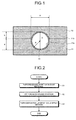
- FIG. 1 is a cross sectional view illustrating a structure of a pipe embedded structure according to an embodiment of the present invention.
- a pipe embedded structure 1 according to the present embodiment includes: a pipe 10 made of a metal or an alloy and having a periphery that forms a circular shape in a transverse section; a base material 11 made of a metal or an alloy, including a recessed portion 11a to which the pipe is fitted; and a deposited layer 12 made of a metal or an alloy and formed on the pipe 10 and the base material 11.
- a pipe embedded structure 1 circulates a desired fluid (a liquid or a gas) in the pipe 10, and is used as a temperature adjustment device (for example, a cold plate), a fluid supply device (for example, a shower plate), or the like.
- the pipe 10 is a pipe having a tube shaped cross section with an outer diameter ⁇ and a curvature R of the periphery. Note that the thickness of the pipe 10 is appropriately determined according to the use or the material.
- the shape of the pipe 10 in a length direction is not especially limited, and the planar shape of the pipe 10 as viewed from above of the pipe embedded structure 1 can be various shapes, such as a linear shape, a spiral shape or a meandering shape.
- the material of the pipe 10 is selected according to the fluid to be circulated in the pipe 10 or the use of the pipe embedded structure 1.
- a metal or an alloy having corrosion resistance such as stainless steel, a copper alloy, a nickel alloy, tantalum, niobium, or titanium
- a material having favorable thermal conductivity such as stainless steel, of the above-described materials
- PCW process cooling water
- the corrosion resistance is not essential, and aluminum or an aluminum alloy having excellent thermal conductivity can be used.
- the base material 11 is a bulk material formed of a metal or a metal alloy having favorable thermal conductivity, such as copper, a copper alloy, aluminum, or an aluminum alloy.
- the recessed portion 11a is formed such that an upper surface 11b of the base material 11 is drilled in a groove manner. Note that the planar shape of the recessed portion 11a on the upper surface 11b corresponds to the planar shape of the pipe 10.
- the recessed portion 11a has an inner wall on which a part of the periphery of the pipe 10 abuts.
- the transverse section shape of the inner wall of the recessed portion 11a is an arc shape along the periphery of the pipe 10.
- the depth d of the recessed portion 11a is defined such that a ratio h/R of a height (hereinafter, referred to as protruding amount) h by which the pipe 10 protrudes from the upper surface 11b, and the curvature R of the periphery of the pipe 10 becomes not smaller than 0.3 and not greater than 0.7.
- the width of the recessed portion 11a has a maximum value w (w ⁇ ⁇ ) at a height corresponding to the curvature R, based on a deepest portion of the recessed portion 11a, and the recessed portion 11a opens from the height to an upper portion while maintaining the maximum value w.
- a clearance w - ⁇ of the recessed portion 11a and the pipe 10 falls within a range from 0 to 0.05 mm, both inclusive.
- the deposited layer 12 is formed by a so-called cold spray method.
- the cold spray method is a coating film forming method, which accelerates powder made of a metal or an alloy together with a gas, and sprays the powder with the gas on a surface of a base (the pipe 10 and the base material 11 in the present embodiment) while maintaining a solid phase state of the powder, thereby to deposit the powder.
- the deposited layer 12 formed by the cold spray method does not have phase transformation, and oxidization is suppressed. Therefore, the deposited layer 12 has high thermal conductivity. Further, when the powder collides with the base or the coating film deposited on the base before, plastic deformation is caused between the powder and the base, and anchor effect can be obtained. In addition, oxide coating films of both sides are destroyed and metallic bond by newly formed surfaces is caused. Therefore, the adhesive strength of the powder with the base becomes strong, and a coating film with suppressed thermal resistance can be formed.
- Such a deposited layer 12 is formed of a metal or an alloy having favorable thermal conductivity, such as copper or aluminum.
- FIG. 2 is a flowchart illustrating a method of manufacturing the pipe embedded structure 1.
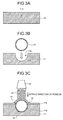
- FIGS. 3A to 3C are schematic diagrams for describing the method of manufacturing the pipe embedded structure 1.
- the groove-shaped recessed portion 11a is formed on a surface of a bulk material 13 made of a metal or an alloy by drilling, and the base material 11 is made, as illustrated in FIG. 3A .
- the deposited layer 12 is formed on the surfaces of the pipe 10 and the base material 11 by the cold spray method, as illustrated in FIG. 3C .
- FIG. 4 is a schematic diagram illustrating an overview of a cold spray device used in process S3.
- a cold spray device 20 includes a gas heater 21, a powder supply device 22, a gas nozzle 24, and valves 25 and 26.
- the gas heater 21 heats a compressed gas.
- the powder supply device 22 houses powder (hereinafter, may be simply referred to as powder) 28 of the material of the deposited layer 12, and supplies the powder 28 to a spray gun 23.
- the gas nozzle 24 jets the heated compressed gas and the powder 28 supplied thereto to a base 27.
- the valves 25 and 26 respectively adjust supply amounts of the compressed gas to the gas heater 21 and to the powder supply device 22.
- the compressed gas helium, nitrogen, oxygen, or the like is used.
- the compressed gas supplied to the gas heater 21 is 50°C or more, for example, and is heated to a temperature in a range lower than a melting point of the powder 28, and is then supplied to the spray gun 23.
- the heating temperature of the compressed gas is favorably 300 to 900°C.
- the compressed gas supplied to the powder supply device 22 supplies the powder 28 in the powder supply device 22 to the spray gun 23 such that the amount of the powder 28 becomes a predetermined discharge amount.
- the heated compressed gas is caused to form ultrasonic flow (about 340 m/s or more) by the gas nozzle 24 having a widening shape from an inlet toward an outlet.
- the gas pressure of the compressed gas at this time is favorably about 1 to 5 MPa.
- the pressure of the compressed gas is favorably about 1 to 5 MPa.
- the processing is performed at a pressure of about 2 to 4 MPa.
- the powder 28 supplied to the spray gun 23 is accelerated by being put into the ultrasonic flow of the compressed gas, collides with the base 27 at a high speed while remaining in the solid phase state, and is deposited on the base 27.
- the cold spray device is not limited to the cold spray device 20 illustrated in FIG. 4 as long as the device can cause the powder 28 to collide with the base 27 while maintaining the solid phase state of the powder 28, and form a coating film.
- the base material 11 obtained such that the pipe 10 is fitted into the recessed portion 11a is arranged, and the coating film is formed on the surfaces of the pipe 10 and the base material 11.
- the powder 28 enters regions 14 between vicinities of upper ends of the recessed portion 11a and the pipe 10, and forms the coating film.
- the pipe embedded structure 1 illustrated in FIG. 1 is completed.
- a part of the pipe 10 rises more than the upper surface 11b of the base material, and thus the deposited layer 12 has a shape rising on an upper portion of the pipe 10. Therefore, the deposited layer 12 is formed thicker, and then an unnecessary portion is removed by cutting or the like, so that the surface of the deposited layer 12 may be flattened.
- the powder 28, which is jetted through the gas nozzle 24 into one direction, is caused to collide with the base 27, and the coating film is formed. Therefore, the coating film cannot be formed on a shaded portion with respect to the jetting direction of the powder 28. Further, formation of the coating film becomes more difficult as a forming surface of the coating film becomes closer to parallel to the jetting direction of the powder 28. Therefore, the inventors of the present application have diligently performed experiments in order to obtain conditions for forming a dense and uniform deposited layer 12 at side portions of the pipe 10, that is, in the vicinities of interfaces between the pipe 10 and the base material 11 when the deposited layer 12 is formed by the cold spray method.
- the inventors of the present application have found out that, when manufacturing the pipe embedded structure 1 in which the pipe 10 having a periphery that forms a circular shape in a transverse section is embedded, the inventors can form the dense and uniform deposited layer 12 adhering to the pipe 10 and the base material 11 by providing the recessed portion 11a that satisfies following conditions (1) and (2) to the base material 11.
- the recessed portion defined by the above-described conditions is formed in the base material, the pipe is fitted into the recessed portion, and the deposited layer is formed by the cold spray method, whereby the dense and uniform deposited layer adhering to the pipe and the base material can be formed around the pipe. Therefore, when the pipe embedded structure having the adhesive properties improved as described above is used as a temperature adjustment device or a shower plate, temperature adjustment efficiency can be improved by the favorable thermal conductivity and thermal uniformity. Note that, in this case, it is favorable to use the deposited layer 12 side as a thermal conduction surface.
- FIGS. 5, 6 , 7A , and 8A are SEM images of the pipe 10, the base material 11, and the deposited layer 12 imaged from a direction perpendicular to the transverse section of the pipe 10, when forming the deposited layer 12 while changing the ratio h/R. Note that, in FIGS. 5, 6 , 7A , and 8A , an interface between a side surface and an upper surface of the base material 11 is illustrated by a single-dotted chain line. Further, a part of an outer diameter of the pipe 10 is supplemented by a broken line.
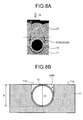
- FIGS. 7B and 8B are schematic diagrams illustrating the positional relationship between the pipe 10 and the base material 11 in the first and second comparative examples.
- Samples were made with following materials and conditions in the first and second examples and the first and second comparative examples.
- the base material a copper alloy plate having 40 mm x 40 mm and the thickness of 10 mm
- the material of the deposited layer copper powder having an average particle diameter of 26.18 ⁇ m
- the ratio h/R was 0.67.
- the dense and uniform deposited layer 12 having a sufficient thickness at the side portions of the pipe 10 was able to be formed, as illustrated in FIG. 5 .
- the ratio h/R was 0.33.
- the dense and uniform deposited layer 12 having a sufficient thickness at the side portions of the pipe 10 was able to be formed, as illustrated in FIG. 6 .
- end portions of the side portions of the pipe 10 that protrudes from the upper surface 11b of the base material 11 were nearly parallel to the jetting direction of the powder, and the powder was not able to adhere to the portions. Therefore, as illustrated in FIG. 7A , the deposited layer 12 was not able to be formed on the side portions of the pipe 10, and cracking was caused between the deposited layer 12 formed on the pipe 10 and the deposited layer 12 formed on the base material 11.
- a deep gap was caused between the inner wall of the recessed portion 11a and the pipe 10, and the powder was not able to be sufficiently filled. Therefore, as illustrated in FIG. 8A , a sufficient deposited layer 12 was not be able to be formed on the side portions of the pipe 10, and cracking was caused between the deposited layer 12 formed on the pipe 10 and the deposited layer 12 formed on the base material 11.
- FIGS. 9 to 11 are optical photographs illustrating the deposited layer 12 when the clearance ⁇ of the recessed portion 11a and the pipe 10 was changed. These optical photographs are polished surfaces of the deposited layer 12 imaged from an upper surface side. The polished surfaces were obtained such that the deposited layer 12 was sufficiently (from an upper end surface of the pipe 10 to the height exceeding 1 mm) formed on the pipe 10, the deposited layer 12 was then cut at the height of 1 mm from the upper end surface of the pipe 10 by milling, and the deposited layer 12 was further polished.
- the base material the copper alloy plate having 40 mm x 40 mm and the thickness of 10 mm
- the material of the deposited layer copper powder having an average particle diameter of 26.18 ⁇ m
- the clearance ⁇ was 0 mm.
- the clearance ⁇ was 0.05 mm.
- the clearance ⁇ was 0.10 mm. In this case, cracking was observed between a region on the pipe 10 and a region on the base material 11, as illustrated in FIG. 11 .
Landscapes
- Engineering & Computer Science (AREA)
- Chemical & Material Sciences (AREA)
- Mechanical Engineering (AREA)
- Physics & Mathematics (AREA)
- Thermal Sciences (AREA)
- General Engineering & Computer Science (AREA)
- Chemical Kinetics & Catalysis (AREA)
- Materials Engineering (AREA)
- Metallurgy (AREA)
- Organic Chemistry (AREA)
- Geometry (AREA)
- Other Surface Treatments For Metallic Materials (AREA)
Abstract
Description
- The present invention relates to a pipe embedded structure in which a pipe is embedded in a metal member, the pipe circulating a temperature adjustment medium, such as a cooling gas or cooling water, and a method of manufacturing the pipe embedded structure.
- Structures (hereinafter, referred to as pipe embedded structures) in which a pipe, which circulates a fluid is embedded in a metal member are used in various uses, such as a process of manufacturing products including semiconductors, liquid crystal display devices, and optical disks. For example, a pipe embedded structure in which a heating medium (coolant) is circulated in the pipe is used as a temperature adjustment device (cold plate, or the like) that adjusts (cools or heats) the temperature of a substrate (for example, see Patent Literature 1). Further, a pipe embedded structure in which a gas containing a predetermined constituent is circulated in a passage is sometimes used as a shower plate that supplies the gas to a substrate.
- Such pipe embedded structures are conventionally manufactured such that the pipe that circulates a fluid, and the metal member in which a recessed portion having a shape corresponding to the pipe is formed by drilling or the like are separately made, and the pipe is fitted into the recessed portion in the metal member.
- Further, in recent years, a technology of embedding a pipe in a metal member by a so-called cold spray method has been proposed, the cold spray method being to spray metal powder on a base material while maintaining a solid phase state of the metal powder, and to deposit the metal on the base material, thereby to form a structure (for example, see Patent Literature 2).
-
- Patent Literature 1: Japanese Laid-open Patent Publication No.
2009-13497 - Patent Literature 2: Japanese Laid-open Patent Publication No.
2011-238705 - In the pipe embedded structures, if a gap exists between the pipe and the metal member, the thermal resistance becomes large, and the thermal conductivity and the thermal uniformity between the fluid circulated in the pipe and the metal member are deteriorated. Further, a foreign body may enter the gap therebetween, or the pipe may be shaky in the recessed portion due to the gap. However, it is difficult to bond them adhering to each other by only the method of simply fitting the pipe in the recessed portion, which is provided in the metal member, so as not to cause the gap between an inner wall of the recessed portion and an external wall of the pipe.
- On this point, with the cold spray method, a dense metal coating film can be deposited around the pipe. Therefore, a structure having excellent thermal conductivity can be made. However, even in this case, adhesive properties of the metal coating film to the pipe may be deteriorated because a local gap is caused around the pipe, depending on a condition, such as the shape of the pipe or an angle at which the metal powder is sprayed on the pipe and the base material.
- The present invention has been made in view of the foregoing, and an objective is to provide a pipe embedded structure with improved adhesive properties between a pipe that forms a passage and a metal member, and a method of manufacturing the pipe embedded structure. Solution to Problem
- To solve the above-described problem and achieve the object, a pipe embedded structure according to the present invention includes: a pipe made of a metal or an alloy, and having a periphery forming a circular shape in a transverse section; a base material made of a metal or an alloy, including a recessed portion having an inner wall on which a part of the periphery abuts and in which the pipe is fitted; and a deposited layer formed by accelerating powder formed of a metal or an alloy together with a gas in a state where the pipe is fitted into the recessed portion, and spraying and depositing the powder on surfaces of the pipe and the base material while maintaining a solid phase state of the powder, wherein a ratio h/R of a protruding amount h by which the pipe protrudes from the surface of the base material and a curvature R of the periphery is not smaller than 0.3 and not greater than 0.7.
- In the above-described pipe embedded structure, in the transverse section of the pipe, a clearance of the recessed portion and the pipe is not smaller than 0 mm and not greater than 0.05 mm.
- In the above-described pipe embedded structure, the pipe is formed of stainless steel, a copper alloy, a nickel alloy, tantalum, niobium, titanium, aluminum, or an aluminum alloy.
- In the above-described pipe embedded structure, the base material is formed of copper, a copper alloy, aluminum, or an aluminum alloy.
- In the above-described pipe embedded structure, the powder is formed of copper or aluminum.
- A method of manufacturing a pipe embedded structure according to the present invention includes: a base material forming step of forming, in a base material made of a metal or an alloy, a recessed portion having an inner wall on which a part of a periphery of a pipe abuts, the pipe being made of a metal or an alloy and having the periphery forming a circular shape in a transverse section; and a deposited layer forming step of forming a deposited layer by fitting the pipe into the recessed portion, accelerating powder formed of a metal or an alloy together with a gas, and spraying and depositing the powder on surfaces of the pipe and the base material while maintaining a solid phase state of the powder, wherein the base material forming step causes a ratio h/R of a protruding amount h by which the pipe protrudes from the surface of the base material and a curvature R of the periphery to be not smaller than 0.3 and not greater than 0.7.
- In the above-described method of manufacturing a pipe embedded structure, the base material forming step causes a clearance of a width of the recessed portion in the transverse section of the pipe and an outer diameter of the pipe to be not smaller than 0 mm and not greater than 0.05 mm.
- According to the present invention, the recessed portion having the ratio h/R not smaller than 0.3 and not greater than 0.7 is formed on the base material, the ratio h/R being a ratio of the protruding amount h of the pipe that forms a passage from the base material, and the curvature R of the periphery of the pipe, the pipe is fitted into the recessed portion, and the deposited layer is formed on the surfaces of the pipe and the base material by a so-called cold spray method. Therefore, a dense deposited layer can be formed around the pipe that protrudes from the base material, and the adhesive properties between the pipe and the metal member can be improved.
-
-
FIG. 1 is a cross sectional view illustrating a structure of a pipe embedded structure according to an embodiment of the present invention. -
FIG. 2 is a flowchart illustrating a method of manufacturing the pipe embedded structure illustrated inFIG. 1 . -
FIG. 3A is a schematic diagram for describing process S1 illustrated inFIG. 2 . -
FIG. 3B is a schematic diagram for describing process S2 illustrated inFIG. 2 . -
FIG. 3C is a schematic diagram for describing process S3 illustrated inFIG. 2 . -
FIG. 4 is a schematic diagram illustrating an overview of a cold spray device. -
FIG. 5 is a SEM image illustrating a deposited layer in a first example. -
FIG. 6 is a SEM image illustrating a deposited layer in a second example. -
FIG. 7A is a SEM image illustrating a deposited layer in a first comparative example. -
FIG. 7B is a schematic diagram illustrating a positional relationship between a pipe and a base material in the first comparative example. -
FIG. 8A is a SEM image illustrating a deposited layer in a second comparative example. -
FIG. 8B is a schematic diagram illustrating a positional relationship between a pipe and a base material in the second comparative example. -
FIG. 9 is an optical photograph illustrating a deposited layer in a third example. -
FIG. 10 is an optical photograph illustrating a deposited layer in a fourth example. -
FIG. 11 is an optical photograph illustrating a deposited layer in a third comparative example. - Hereinafter, embodiments for implementing the present invention will be described in detail with reference to the drawings. Note that the present invention is not limited by the following embodiments. Further, the drawings referred in the following description merely schematically illustrate the shape, the size, and the positional relationship to the extent that the content of the present invention can be understood. That is, the present invention is not limited only by the shape, the size, and the positional relationship exemplarily illustrated in the drawings.
-
FIG. 1 is a cross sectional view illustrating a structure of a pipe embedded structure according to an embodiment of the present invention. As illustrated inFIG. 1 , a pipe embeddedstructure 1 according to the present embodiment includes: apipe 10 made of a metal or an alloy and having a periphery that forms a circular shape in a transverse section; abase material 11 made of a metal or an alloy, including arecessed portion 11a to which the pipe is fitted; and a depositedlayer 12 made of a metal or an alloy and formed on thepipe 10 and thebase material 11. Such a pipe embeddedstructure 1 circulates a desired fluid (a liquid or a gas) in thepipe 10, and is used as a temperature adjustment device (for example, a cold plate), a fluid supply device (for example, a shower plate), or the like. - The
pipe 10 is a pipe having a tube shaped cross section with an outer diameter ϕ and a curvature R of the periphery. Note that the thickness of thepipe 10 is appropriately determined according to the use or the material. - The shape of the
pipe 10 in a length direction (a direction into which the fluid is circulated) is not especially limited, and the planar shape of thepipe 10 as viewed from above of the pipe embeddedstructure 1 can be various shapes, such as a linear shape, a spiral shape or a meandering shape. - The material of the
pipe 10 is selected according to the fluid to be circulated in thepipe 10 or the use of the pipe embeddedstructure 1. For example, when a liquid or a gas having corrosion properties is circulated, a metal or an alloy having corrosion resistance, such as stainless steel, a copper alloy, a nickel alloy, tantalum, niobium, or titanium, is used. Further, when city water or sea water is circulated as cooling water, a material having favorable thermal conductivity, such as stainless steel, of the above-described materials, is used. Meanwhile, when process cooling water (PCW), an organic solvent, an inert gas, or the like is circulated, the corrosion resistance is not essential, and aluminum or an aluminum alloy having excellent thermal conductivity can be used. - The
base material 11 is a bulk material formed of a metal or a metal alloy having favorable thermal conductivity, such as copper, a copper alloy, aluminum, or an aluminum alloy. The recessedportion 11a is formed such that anupper surface 11b of thebase material 11 is drilled in a groove manner. Note that the planar shape of the recessedportion 11a on theupper surface 11b corresponds to the planar shape of thepipe 10. - The recessed
portion 11a has an inner wall on which a part of the periphery of thepipe 10 abuts. The transverse section shape of the inner wall of the recessedportion 11a is an arc shape along the periphery of thepipe 10. The depth d of the recessedportion 11a is defined such that a ratio h/R of a height (hereinafter, referred to as protruding amount) h by which thepipe 10 protrudes from theupper surface 11b, and the curvature R of the periphery of thepipe 10 becomes not smaller than 0.3 and not greater than 0.7. Further, the width of the recessedportion 11a has a maximum value w (w ≅ ϕ) at a height corresponding to the curvature R, based on a deepest portion of the recessedportion 11a, and the recessedportion 11a opens from the height to an upper portion while maintaining the maximum value w. Further, a clearance w - ϕ of the recessedportion 11a and thepipe 10 falls within a range from 0 to 0.05 mm, both inclusive. - The deposited
layer 12 is formed by a so-called cold spray method. Here, the cold spray method is a coating film forming method, which accelerates powder made of a metal or an alloy together with a gas, and sprays the powder with the gas on a surface of a base (thepipe 10 and thebase material 11 in the present embodiment) while maintaining a solid phase state of the powder, thereby to deposit the powder. The depositedlayer 12 formed by the cold spray method does not have phase transformation, and oxidization is suppressed. Therefore, the depositedlayer 12 has high thermal conductivity. Further, when the powder collides with the base or the coating film deposited on the base before, plastic deformation is caused between the powder and the base, and anchor effect can be obtained. In addition, oxide coating films of both sides are destroyed and metallic bond by newly formed surfaces is caused. Therefore, the adhesive strength of the powder with the base becomes strong, and a coating film with suppressed thermal resistance can be formed. - Such a deposited
layer 12 is formed of a metal or an alloy having favorable thermal conductivity, such as copper or aluminum. - Next, a method of manufacturing the pipe embedded
structure 1 will be described.FIG. 2 is a flowchart illustrating a method of manufacturing the pipe embeddedstructure 1. Further,FIGS. 3A to 3C are schematic diagrams for describing the method of manufacturing the pipe embeddedstructure 1. - First, in process S1, the groove-shaped recessed
portion 11a is formed on a surface of abulk material 13 made of a metal or an alloy by drilling, and thebase material 11 is made, as illustrated inFIG. 3A . - Next, in process S2, the
pipe 10 is fitted into the recessedportion 11a, as illustrated inFIG. 3B . - Further, in process S3, the deposited
layer 12 is formed on the surfaces of thepipe 10 and thebase material 11 by the cold spray method, as illustrated inFIG. 3C . -
FIG. 4 is a schematic diagram illustrating an overview of a cold spray device used in process S3. As illustrated inFIG. 4 , acold spray device 20 includes agas heater 21, apowder supply device 22, agas nozzle 24, andvalves gas heater 21 heats a compressed gas. Thepowder supply device 22 houses powder (hereinafter, may be simply referred to as powder) 28 of the material of the depositedlayer 12, and supplies thepowder 28 to aspray gun 23. Thegas nozzle 24 jets the heated compressed gas and thepowder 28 supplied thereto to abase 27. Thevalves gas heater 21 and to thepowder supply device 22. - As the compressed gas, helium, nitrogen, oxygen, or the like is used. The compressed gas supplied to the
gas heater 21 is 50°C or more, for example, and is heated to a temperature in a range lower than a melting point of thepowder 28, and is then supplied to thespray gun 23. The heating temperature of the compressed gas is favorably 300 to 900°C. Meanwhile, the compressed gas supplied to thepowder supply device 22 supplies thepowder 28 in thepowder supply device 22 to thespray gun 23 such that the amount of thepowder 28 becomes a predetermined discharge amount. - The heated compressed gas is caused to form ultrasonic flow (about 340 m/s or more) by the
gas nozzle 24 having a widening shape from an inlet toward an outlet. The gas pressure of the compressed gas at this time is favorably about 1 to 5 MPa. By adjusting the pressure of the compressed gas to the range, the adhesive strength of the powder (coating film) with respect to the base 27 can be improved. More favorably, the processing is performed at a pressure of about 2 to 4 MPa. Thepowder 28 supplied to thespray gun 23 is accelerated by being put into the ultrasonic flow of the compressed gas, collides with the base 27 at a high speed while remaining in the solid phase state, and is deposited on thebase 27. Note that the cold spray device is not limited to thecold spray device 20 illustrated inFIG. 4 as long as the device can cause thepowder 28 to collide with the base 27 while maintaining the solid phase state of thepowder 28, and form a coating film. - In such a
cold spray device 20, as thebase 27, thebase material 11 obtained such that thepipe 10 is fitted into the recessedportion 11a is arranged, and the coating film is formed on the surfaces of thepipe 10 and thebase material 11. At this time, thepowder 28 entersregions 14 between vicinities of upper ends of the recessedportion 11a and thepipe 10, and forms the coating film. - As described above, by forming the deposited
layer 12 to have a desired thickness, the pipe embeddedstructure 1 illustrated inFIG. 1 is completed. Note that, as illustrated inFIG. 3C , a part of thepipe 10 rises more than theupper surface 11b of the base material, and thus the depositedlayer 12 has a shape rising on an upper portion of thepipe 10. Therefore, the depositedlayer 12 is formed thicker, and then an unnecessary portion is removed by cutting or the like, so that the surface of the depositedlayer 12 may be flattened. - Next, the relationship between the transverse section of the
pipe 10 and the recessedportion 11a provided in thebase material 11 will be described. - In the cold spray method, typically, the
powder 28, which is jetted through thegas nozzle 24 into one direction, is caused to collide with thebase 27, and the coating film is formed. Therefore, the coating film cannot be formed on a shaded portion with respect to the jetting direction of thepowder 28. Further, formation of the coating film becomes more difficult as a forming surface of the coating film becomes closer to parallel to the jetting direction of thepowder 28. Therefore, the inventors of the present application have diligently performed experiments in order to obtain conditions for forming a dense and uniform depositedlayer 12 at side portions of thepipe 10, that is, in the vicinities of interfaces between thepipe 10 and thebase material 11 when the depositedlayer 12 is formed by the cold spray method. - As a result, the inventors of the present application have found out that, when manufacturing the pipe embedded
structure 1 in which thepipe 10 having a periphery that forms a circular shape in a transverse section is embedded, the inventors can form the dense and uniform depositedlayer 12 adhering to thepipe 10 and thebase material 11 by providing the recessedportion 11a that satisfies following conditions (1) and (2) to thebase material 11. - (1) The radio h/R of the protruding amount h by which the
pipe 10 protrudes from the surface of thebase material 11, and the curvature R of the periphery of thepipe 10 is caused to be from 0.3 to 0.7, both inclusive. - (2) The clearance Δ of the recessed
portion 11a and thepipe 10 is caused to be from 0 to 0.05 mm, both inclusive. - According to the present embodiment, the recessed portion defined by the above-described conditions is formed in the base material, the pipe is fitted into the recessed portion, and the deposited layer is formed by the cold spray method, whereby the dense and uniform deposited layer adhering to the pipe and the base material can be formed around the pipe. Therefore, when the pipe embedded structure having the adhesive properties improved as described above is used as a temperature adjustment device or a shower plate, temperature adjustment efficiency can be improved by the favorable thermal conductivity and thermal uniformity. Note that, in this case, it is favorable to use the deposited
layer 12 side as a thermal conduction surface. - Hereinafter, examples and comparative examples will be described with reference to
FIGS. 5 to 11 . - First, first and second examples and first and second comparative examples will be described.
FIGS. 5, 6 ,7A , and8A are SEM images of thepipe 10, thebase material 11, and the depositedlayer 12 imaged from a direction perpendicular to the transverse section of thepipe 10, when forming the depositedlayer 12 while changing the ratio h/R. Note that, inFIGS. 5, 6 ,7A , and8A , an interface between a side surface and an upper surface of thebase material 11 is illustrated by a single-dotted chain line. Further, a part of an outer diameter of thepipe 10 is supplemented by a broken line.FIGS. 7B and8B are schematic diagrams illustrating the positional relationship between thepipe 10 and thebase material 11 in the first and second comparative examples. - Samples were made with following materials and conditions in the first and second examples and the first and second comparative examples.
- The base material: a copper alloy plate having 40 mm x 40 mm and the thickness of 10 mm
- The pipe: a copper alloy having the outer diameter ϕ = 6 mm and the curvature R of the periphery = 3 mm
- The material of the deposited layer: copper powder having an average particle diameter of 26.18 µm
- The clearance of the recessed portion provided in the base material and the pipe: Δ = 0 mm
- The ratio h/R was 0.67. As a result, the dense and uniform deposited
layer 12 having a sufficient thickness at the side portions of thepipe 10 was able to be formed, as illustrated inFIG. 5 . - The ratio h/R was 0.33. As a result, the dense and uniform deposited
layer 12 having a sufficient thickness at the side portions of thepipe 10 was able to be formed, as illustrated inFIG. 6 . - The ratio h/R was 1 (the protruding amount h = the curvature R), that is, the recessed
portion 11a having a depth corresponding to half of the outer diameter ϕ of thepipe 10 was formed in thebase material 11, and just half of thepipe 10 was housed in the recessedportion 11a. In this case, as illustrated inFIG. 7B , end portions of the side portions of thepipe 10 that protrudes from theupper surface 11b of thebase material 11 were nearly parallel to the jetting direction of the powder, and the powder was not able to adhere to the portions. Therefore, as illustrated inFIG. 7A , the depositedlayer 12 was not able to be formed on the side portions of thepipe 10, and cracking was caused between the depositedlayer 12 formed on thepipe 10 and the depositedlayer 12 formed on thebase material 11. - The ratio h/R was 0 (the protruding amount h = 0), that is, the recessed
portion 11a having a depth corresponding to the outer diameter ϕ of thepipe 10 was formed in thebase material 11, and theentire pipe 10 was housed in the recessedportion 11a. In this case, as illustrated inFIG. 8B , a deep gap was caused between the inner wall of the recessedportion 11a and thepipe 10, and the powder was not able to be sufficiently filled. Therefore, as illustrated inFIG. 8A , a sufficient depositedlayer 12 was not be able to be formed on the side portions of thepipe 10, and cracking was caused between the depositedlayer 12 formed on thepipe 10 and the depositedlayer 12 formed on thebase material 11. - Next, third and fourth examples and a third comparative example will be described.
FIGS. 9 to 11 are optical photographs illustrating the depositedlayer 12 when the clearance Δ of the recessedportion 11a and thepipe 10 was changed. These optical photographs are polished surfaces of the depositedlayer 12 imaged from an upper surface side. The polished surfaces were obtained such that the depositedlayer 12 was sufficiently (from an upper end surface of thepipe 10 to the height exceeding 1 mm) formed on thepipe 10, the depositedlayer 12 was then cut at the height of 1 mm from the upper end surface of thepipe 10 by milling, and the depositedlayer 12 was further polished. - In the third and fourth examples and the third comparative example, samples were made with following materials and conditions.
- The base material: the copper alloy plate having 40 mm x 40 mm and the thickness of 10 mm
- The pipe: a copper alloy having the outer diameter ϕ = 6 mm and the curvature R of the periphery = 3 mm
- The material of the deposited layer: copper powder having an average particle diameter of 26.18 µm
- The ratio h/R = 0.5
- The clearance Δ was 0 mm. As a result, a dense and uniform deposited
layer 12 smoothly continuous with a region on thepipe 10 and a region on thebase material 11 was able to be formed, as illustrated inFIG. 9 . - The clearance Δ was 0.05 mm. As a result, a dense and uniform deposited
layer 12 smoothly continuous with a region on thepipe 10 and a region on thebase material 11 was able to be formed, although interface lines of surfaces were observed between the region on thepipe 10 and the region on thebase material 11, as illustrated inFIG. 10 . - The clearance Δ was 0.10 mm. In this case, cracking was observed between a region on the
pipe 10 and a region on thebase material 11, as illustrated inFIG. 11 . Reference Signs List -
- 1
- Pipe embedded structure
- 10
- Pipe
- 11
- Base material
- 11a
- Recessed portion
- 11b
- Upper surface
- 12
- Deposited layer
- 13
- Bulk material
- 14
- Regions
- 20
- Cold spray device
- 21
- Gas heater
- 22
- Powder supply device
- 23
- Spray gun
- 24
- Gas nozzle
- 25
- and 26 Valve
- 27
- Base
- 28
- Powder
Claims (7)
- A pipe embedded structure comprising:a pipe made of a metal or an alloy, and having a periphery forming a circular shape in a transverse section;a base material made of a metal or an alloy, comprising a recessed portion having an inner wall on which a part of the periphery abuts and in which the pipe is fitted; anda deposited layer formed by accelerating powder formed of a metal or an alloy together with a gas in a state where the pipe is fitted into the recessed portion, and spraying and depositing the powder on surfaces of the pipe and the base material while maintaining a solid phase state of the powder, whereina ratio h/R of a protruding amount h by which the pipe protrudes from the surface of the base material and a curvature R of the periphery is not smaller than 0.3 and not greater than 0.7.
- The pipe embedded structure according to claim 1, wherein, in the transverse section of the pipe, a clearance of the recessed portion and the pipe is not smaller than 0 mm and not greater than 0.05 mm.
- The pipe embedded structure according to claim 1 or 2, wherein the pipe is formed of stainless steel, a copper alloy, a nickel alloy, tantalum, niobium, titanium, aluminum, or an aluminum alloy.
- The pipe embedded structure according to any one of claims 1 to 3, wherein the base material is formed of copper, a copper alloy, aluminum, or an aluminum alloy.
- The pipe embedded structure according to claim 4, wherein the powder is formed of copper or aluminum.
- A method of manufacturing a pipe embedded structure, the method comprising:a base material forming step of forming, in a base material made of a metal or an alloy, a recessed portion having an inner wall on which a part of a periphery of a pipe abuts, the pipe being made of a metal or an alloy and having the periphery forming a circular shape in a transverse section; anda deposited layer forming step of forming a deposited layer by fitting the pipe into the recessed portion, accelerating powder formed of a metal or an alloy together with a gas, and spraying and depositing the powder on surfaces of the pipe and the base material while maintaining a solid phase state of the powder, whereinthe base material forming step causes a ratio h/R of a protruding amount h by which the pipe protrudes from the surface of the base material and a curvature R of the periphery to be not smaller than 0.3 and not greater than 0.7.
- The method of manufacturing a pipe embedded structure according to claim 6, wherein the base material forming step causes a clearance of a width of the recessed portion in the transverse section of the pipe and an outer diameter of the pipe to be not smaller than 0 mm and not greater than 0.05 mm.
Applications Claiming Priority (2)
| Application Number | Priority Date | Filing Date | Title |
|---|---|---|---|
| JP2012149972A JP5386615B1 (en) | 2012-07-03 | 2012-07-03 | Pipe embedded structure and manufacturing method thereof |
| PCT/JP2013/068077 WO2014007226A1 (en) | 2012-07-03 | 2013-07-01 | Structure with embedded pipe and manufacturing method therefor |
Publications (2)
| Publication Number | Publication Date |
|---|---|
| EP2871262A1 true EP2871262A1 (en) | 2015-05-13 |
| EP2871262A4 EP2871262A4 (en) | 2016-03-23 |
Family
ID=49881982
Family Applications (1)
| Application Number | Title | Priority Date | Filing Date |
|---|---|---|---|
| EP13813481.2A Withdrawn EP2871262A4 (en) | 2012-07-03 | 2013-07-01 | STRUCTURE IN WHICH A PIPE IS INTEGRATED, AND METHOD FOR MANUFACTURING SAME |
Country Status (6)
| Country | Link |
|---|---|
| US (1) | US20150198387A1 (en) |
| EP (1) | EP2871262A4 (en) |
| JP (1) | JP5386615B1 (en) |
| KR (1) | KR20150015533A (en) |
| CN (1) | CN104395501A (en) |
| WO (1) | WO2014007226A1 (en) |
Families Citing this family (3)
| Publication number | Priority date | Publication date | Assignee | Title |
|---|---|---|---|---|
| JP6178217B2 (en) * | 2013-11-13 | 2017-08-09 | 株式会社東芝 | Heat transfer tube mounting structure and mounting method |
| JP6437365B2 (en) * | 2015-03-30 | 2018-12-12 | タツタ電線株式会社 | Fixing method, covered conductor fixing structure |
| EP3381874A1 (en) * | 2017-03-31 | 2018-10-03 | Arkema B.V. | Feeding device for coating apparatus, coating apparatus comprising it and process using it |
Family Cites Families (14)
| Publication number | Priority date | Publication date | Assignee | Title |
|---|---|---|---|---|
| US5180254A (en) * | 1989-04-10 | 1993-01-19 | Marcel Matiere | Fluid-conveying conduit |
| JPH05134067A (en) * | 1991-11-14 | 1993-05-28 | Toshiba Corp | Manufacture of heat-receiving plate having cooling structure |
| ES2170328T3 (en) * | 1997-02-20 | 2002-08-01 | Ccs Technology Inc | PROCEDURE TO INTRODUCE AN OPTICAL OR ELECTRIC CABLE IN A FIRST FLOOR AND DEVICE FOR THE INTRODUCTION OF THE CABLE. |
| US6405785B1 (en) * | 2000-01-28 | 2002-06-18 | Mold-Masters Limited | Injection molding component with heating element and method of making |
| DE10025588A1 (en) * | 2000-05-24 | 2001-11-29 | Mold Masters Ltd | Unit with heater, thermocouple, sensor, heating and cooling lines, useful in molding equipment, embeds heater in depression, below thermally-sprayed covering |
| US7730908B2 (en) * | 2006-03-24 | 2010-06-08 | Babcock & Wilcox Power Generation Group, Inc. | Self supporting reinforced header |
| KR20090001091A (en) | 2007-06-29 | 2009-01-08 | (주)티티에스 | Semiconductor manufacturing device composed of external heating element |
| JP4737170B2 (en) * | 2007-10-02 | 2011-07-27 | 関東自動車工業株式会社 | Method for manufacturing mold shell having temperature control member |
| AU2009312245C1 (en) * | 2008-11-04 | 2013-04-18 | Daikin Industries, Ltd. | Cooling member, and method and device for manufacturing same |
| US20100170937A1 (en) * | 2009-01-07 | 2010-07-08 | General Electric Company | System and Method of Joining Metallic Parts Using Cold Spray Technique |
| US8087431B2 (en) * | 2009-05-24 | 2012-01-03 | Pipe Wrap, LLC | Wear pad |
| DE102009049479B4 (en) * | 2009-06-08 | 2024-07-04 | Sms Group Gmbh | Integration of an optical fiber of a measuring sensor into a component |
| JP5162621B2 (en) | 2010-05-07 | 2013-03-13 | 日本発條株式会社 | Temperature control device, cooling device, and method of manufacturing temperature control device |
| CN201907053U (en) * | 2010-12-11 | 2011-07-27 | 昆明台兴精密机械有限责任公司 | Cooler for main shaft millstone of wafer single-side polisher |
-
2012
- 2012-07-03 JP JP2012149972A patent/JP5386615B1/en not_active Expired - Fee Related
-
2013
- 2013-07-01 CN CN201380033889.7A patent/CN104395501A/en active Pending
- 2013-07-01 EP EP13813481.2A patent/EP2871262A4/en not_active Withdrawn
- 2013-07-01 KR KR20147036856A patent/KR20150015533A/en not_active Ceased
- 2013-07-01 US US14/409,725 patent/US20150198387A1/en not_active Abandoned
- 2013-07-01 WO PCT/JP2013/068077 patent/WO2014007226A1/en not_active Ceased
Also Published As
| Publication number | Publication date |
|---|---|
| JP5386615B1 (en) | 2014-01-15 |
| JP2014012865A (en) | 2014-01-23 |
| US20150198387A1 (en) | 2015-07-16 |
| WO2014007226A1 (en) | 2014-01-09 |
| KR20150015533A (en) | 2015-02-10 |
| EP2871262A4 (en) | 2016-03-23 |
| CN104395501A (en) | 2015-03-04 |
Similar Documents
| Publication | Publication Date | Title |
|---|---|---|
| JP5162621B2 (en) | Temperature control device, cooling device, and method of manufacturing temperature control device | |
| EP2592647B1 (en) | Manufacturing method for plate | |
| RU2469126C2 (en) | Method of applying coating on substrate surface and coated product | |
| US20200166299A1 (en) | Heat Exchange Element and Process for Production | |
| CN109989058A (en) | High purity metal top coating for semiconductor processing components | |
| EP3392378A1 (en) | Method for coating steel plate with metal and metal-coated steel plate manufactured using same | |
| US20150198387A1 (en) | Pipe embedded structure and method of manufacturing the same | |
| EP2871261A1 (en) | Structure with embedded pipe and manufacturing method therefor | |
| US20200024746A1 (en) | Manufactured metal objects with hollow channels and method for fabrication thereof | |
| JP5734129B2 (en) | Member with flow path and manufacturing method thereof | |
| Wang et al. | Simulation of flow field based on constrained fluid for electrolyte jet control | |
| TWI484557B (en) | Member with flow path and method for manufacturing thereof | |
| GB2564902A (en) | Heat exchange element and process for production | |
| GB2565276A (en) | Electroless flow deposition process |
Legal Events
| Date | Code | Title | Description |
|---|---|---|---|
| PUAI | Public reference made under article 153(3) epc to a published international application that has entered the european phase |
Free format text: ORIGINAL CODE: 0009012 |
|
| 17P | Request for examination filed |
Effective date: 20141223 |
|
| AK | Designated contracting states |
Kind code of ref document: A1 Designated state(s): AL AT BE BG CH CY CZ DE DK EE ES FI FR GB GR HR HU IE IS IT LI LT LU LV MC MK MT NL NO PL PT RO RS SE SI SK SM TR |
|
| AX | Request for extension of the european patent |
Extension state: BA ME |
|
| DAX | Request for extension of the european patent (deleted) | ||
| RA4 | Supplementary search report drawn up and despatched (corrected) |
Effective date: 20160218 |
|
| RIC1 | Information provided on ipc code assigned before grant |
Ipc: C23C 24/04 20060101AFI20160212BHEP Ipc: F16L 1/00 20060101ALI20160212BHEP |
|
| STAA | Information on the status of an ep patent application or granted ep patent |
Free format text: STATUS: THE APPLICATION IS DEEMED TO BE WITHDRAWN |
|
| 18D | Application deemed to be withdrawn |
Effective date: 20160920 |