EP2871031A2 - Disposable production line for filling and finishing a product - Google Patents
Disposable production line for filling and finishing a product Download PDFInfo
- Publication number
- EP2871031A2 EP2871031A2 EP20140189523 EP14189523A EP2871031A2 EP 2871031 A2 EP2871031 A2 EP 2871031A2 EP 20140189523 EP20140189523 EP 20140189523 EP 14189523 A EP14189523 A EP 14189523A EP 2871031 A2 EP2871031 A2 EP 2871031A2
- Authority
- EP
- European Patent Office
- Prior art keywords
- vessel
- products
- product
- closure
- platform
- Prior art date
- Legal status (The legal status is an assumption and is not a legal conclusion. Google has not performed a legal analysis and makes no representation as to the accuracy of the status listed.)
- Granted
Links
- 238000004519 manufacturing process Methods 0.000 title description 3
- 238000005303 weighing Methods 0.000 claims abstract description 22
- 238000012545 processing Methods 0.000 claims abstract description 12
- 239000002510 pyrogen Substances 0.000 claims abstract description 10
- 238000000034 method Methods 0.000 claims abstract description 8
- 238000007599 discharging Methods 0.000 claims abstract description 5
- 230000001698 pyrogenic effect Effects 0.000 claims description 4
- 238000003466 welding Methods 0.000 claims description 2
- 238000012546 transfer Methods 0.000 description 26
- 230000001105 regulatory effect Effects 0.000 description 6
- 238000012986 modification Methods 0.000 description 3
- 230000004048 modification Effects 0.000 description 3
- 239000000126 substance Substances 0.000 description 3
- 150000001875 compounds Chemical class 0.000 description 2
- 239000000463 material Substances 0.000 description 2
- 239000004698 Polyethylene Substances 0.000 description 1
- 238000004140 cleaning Methods 0.000 description 1
- 238000004891 communication Methods 0.000 description 1
- 238000004320 controlled atmosphere Methods 0.000 description 1
- 230000001276 controlling effect Effects 0.000 description 1
- 238000011143 downstream manufacturing Methods 0.000 description 1
- 239000000945 filler Substances 0.000 description 1
- 238000005429 filling process Methods 0.000 description 1
- 238000000465 moulding Methods 0.000 description 1
- 238000004806 packaging method and process Methods 0.000 description 1
- 239000004033 plastic Substances 0.000 description 1
- 229920003023 plastic Polymers 0.000 description 1
- -1 polyethylene Polymers 0.000 description 1
- 229920000573 polyethylene Polymers 0.000 description 1
- 238000003825 pressing Methods 0.000 description 1
- 238000007789 sealing Methods 0.000 description 1
- 230000001954 sterilising effect Effects 0.000 description 1
- 238000004659 sterilization and disinfection Methods 0.000 description 1
Images


Classifications
-
- B—PERFORMING OPERATIONS; TRANSPORTING
- B65—CONVEYING; PACKING; STORING; HANDLING THIN OR FILAMENTARY MATERIAL
- B65B—MACHINES, APPARATUS OR DEVICES FOR, OR METHODS OF, PACKAGING ARTICLES OR MATERIALS; UNPACKING
- B65B55/00—Preserving, protecting or purifying packages or package contents in association with packaging
- B65B55/02—Sterilising, e.g. of complete packages
- B65B55/027—Packaging in aseptic chambers
-
- B—PERFORMING OPERATIONS; TRANSPORTING
- B25—HAND TOOLS; PORTABLE POWER-DRIVEN TOOLS; MANIPULATORS
- B25J—MANIPULATORS; CHAMBERS PROVIDED WITH MANIPULATION DEVICES
- B25J21/00—Chambers provided with manipulation devices
- B25J21/02—Glove-boxes, i.e. chambers in which manipulations are performed by the human hands in gloves built into the chamber walls; Gloves therefor
Definitions
- This invention relates to a disposable production line for processing, manipulating, manufacturing and/or packaging products or devices under an inert atmosphere, and/or sterile conditions and/or a pyrogen free environment.
- This invention further relates to U.S. Patent Application Pub. Nos. 2012/0031042 and 2012/0294697 to Zambaux , the disclosures of which are incorporated herein by reference.
- the apparatus includes a vessel including an inlet for receiving the one or more products and an outlet for discharging the one or more products under sterile and/or pyrogen free conditions.
- a device such as a tool, is adapted for applying the closure to the one or more products in the vessel.
- the device comprises a sleeve connected to a wall of the vessel, such as the top wall.
- the sleeve may comprise a flexible sleeve having a rigid portion adapted for applying the closure to at least one product.
- the rigid portion may be adapted for applying a closure to each of a plurality of products simultaneously.
- the apparatus may further include a platform in the vessel opposite the device for supporting the one or more products, which platform may be connected to a motive device and move from the inlet to the outlet of the vessel.
- the device may comprise a tool in the form of a press.
- the press may be positioned in the sleeve, and the vessel may comprise at least one flexible wall (such as part of a flexible bag).
- the apparatus may further include a scale associated with the vessel for weighing the one or more products before or after applying the closure.
- a platform may be provided for supporting the product or products for being weighed on the scale.
- a conduit for pressurizing the vessel may also be provided.
- the apparatus may include a glove attached to the vessel for manipulating one or more of the product, the device, or the closure, and a basket or tray may support a plurality of products in the vessel.
- the device may be adapted to apply a closure to the plurality of products in a simultaneous fashion while positioned in the basket or tray.
- a further aspect of the disclosure relates to the foregoing system, and further including an apparatus comprising a filler or filling means for filling the product prior to passing the product to the vessel for receiving the closure.
- Still another aspect of the disclosure pertains to an apparatus for processing one or more products.
- the apparatus comprises a vessel including an inlet for receiving the one or more products and an outlet for discharging the one or more products under sterile and/or pyrogen free conditions.
- a platform for supporting the one or more products in the vessel is adapted for moving toward the inlet or the outlet of the vessel.
- a motive device may be provided for moving the platform, which may be connected to a wall of the vessel between the inlet and the outlet.
- a further aspect of the disclosure relates to a method of processing a product.
- the method comprises applying a closure to the product using a press contained at least partially within a sleeve projecting into a compartment of a vessel under sterile and/or pyrogenic conditions.
- a further aspect relates to a method of processing a product comprising moving a product on a platform in a compartment of a vessel under sterile or pyrogenic conditions from closer to an inlet of the vessel to closer to an outlet of the vessel. Either method may further include the step of filling the product prior to the step of applying the closure or moving the product.
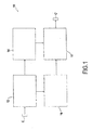
- a system 10 for processing a product under an inert atmosphere, under sterile conditions, and/or in a pyrogen free environment is disclosed.
- the system 10 may include a plurality of isolators, which may be connected to one another to complete the system 10.
- the system 10 includes a first transfer isolator 12, a second transfer isolator 14, a filling isolator 16, and a weighing and capping isolator 18.
- Each of the isolators 12, 14 may include at least one flexible wall, and may be in the form of a flexible and/or disposable vessel, such as a bag.
- the first transfer isolator 12 may include at least one inlet 20 and one or more outlets 22. Each of the inlet(s) 20 and the outlet(s) 22 may comprise a port for sealing with another isolator or other container under a controlled atmosphere, sterile and/or pyrogen free conditions.
- the first transfer isolator 12 may include one or more regulating ports 27, which may be attached to a gas tube 28 that may be used to inflate and/or deflate the first transfer isolator 12, and/or to introduce a sterile, inert, and/or pyrogen free gas to create a desired atmosphere within the first transfer isolator. These regulating ports 27 and/or gas tubes 28 may be used to control and/or manipulate the pressure within an isolator.
- the first transfer isolator 12 may further include one or more glove ports 24 for allowing access to manipulations of the contents of an interior of the first transfer isolator 12 in a sealed manner. These glove ports 24 may be connected to one or more gloves 25.
- the gloves 25 may be located on two or more sides of the isolator, such as on opposite sides, so as to allow for two or more people to work in the isolator at the same time.
- Each side of the isolator 12 may include upper gloves and lower gloves, so as to allow an operator to work from both a standing and a sitting position.
- Sterile and/or pyrogen free containers C may be transported in a transfer station (not shown) that may be linked to the inlet 20 of the first transfer isolator 12.
- the transfer station may be disposable or non-disposable in nature.
- the system 10 Once linked, the system 10 may be considered a closed system, with each isolator or other container being linked by connectors, such as flexible tubes. These connectors may be of the type disclosed in either of U.S. Patent App. Pub. Nos. 2012/0031042 or 2012/0294697 .
- the connectors may be closed off by doors 26 on each side of the connector (to initially isolate each section from the other sections and to allow for cleaning and sterilization of the connectors). Once the transfer station is attached, all the doors 26 may be removed.
- the containers C may then be passed into the first transfer isolator 12 through the inlet 20 and uncapped therein. The uncapped containers may be placed into a tray or basket and the caps may be placed in a different tray or basket.
- the first transfer isolator 12 may have plural outlets 22.
- the closure, caps or other pieces for use in assembling the product may be passed through one of the outlets to the second transfer isolator 14.
- the products, such as uncapped containers C, may be passed through the second of the two outlets to the filling isolator 16.
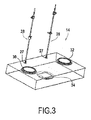
- FIG. 3 illustrates the second transfer isolator 14 in further detail.
- the second transfer isolator 14 may include one or more inlets 30 and one or more outlets 32.
- the second transfer isolator 14 includes a single inlet and a single outlet.
- the second transfer isolator 14 may also include one or more regulating ports 27 and/or gas tubes 28 for regulating the atmosphere within the second transfer isolator 14.
- a platform 34 may be included in the second transfer isolator 14 for facilitating movement of items, such as products, within the isolator.
- the platform 34 may interact with a motive device outside of the isolator for manipulating a position of the platform within the interior of the second transfer isolator 14.
- the motive device may include an electronic motor and/or a manual motive device.
- the platform 34 may be connected to the wall of the second transfer isolator 14, such as by welding, and may be provided with sufficient flexible material to allow for the platform to move within the interior of the isolator. In use, the platform 34 may be moved closer to the inlet 30 to receive items from the first transfer isolator 12, such as caps removed from the containers C. The platform 34 may then be moved closer to the outlet 32 to allow passage of items, such as uncapped containers, for downstream processing, such as to the weighing and capping isolator 18.
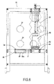
- FIG. 4 One example of a filling isolator 16 is shown in further detail in Figure 4 .
- This particular filling isolator 16 includes an inlet 40 for receiving items, such as from the first transfer isolator 12.
- An outlet 42 may also be included in the filling isolator 16, such as for delivering filled containers to the weighing and capping isolator 18.
- the filling isolator 16 may include a dispenser, such as a filling means 46, for dispensing a product into a container C within the isolator.
- the filling means 46 may include a needle in communication with a conduit and a source of the substance to be used to fill the container C, and may be similar to that which is disclosed in U.S. Patent App. Pub. No. 2012/0031042 .
- the filling isolator 16 may also include one or more regulating ports 27 and/or gas tubes 28 for regulating the atmosphere within the isolator.
- the filling isolator 16 may include a platform 44, which may be moveable within the interior of the isolator.
- the platform 44 may interact with a motive device as described above for controlling the position of the platform.
- a carrier such as a tray or basket, carrying the uncapped container(s) may be placed on the platform 44.
- An actuator may cause the filling means 46 and the platform 44 to align with one another to facilitate filling of the container(s).
- the filling isolator including a flexible wall and the filling means 46 is connected to it, this allows for the filling means 46 to be lowered into each container and fill the container C with a given substance.
- the platform 44 may be automatically shifted according to preset specifications until plural containers C in a particular group are filled.
- the platform 44 may be manipulated to a position close enough to the outlet 42 so that the filled containers may be passed into the weighing and capping isolator 18, and then alight as completed containers C' from the associated outlet.
- the weighing and capping isolator 18 is shown in further detail in Figures 5-7 .
- This isolator 18 may include two inlets 50a, 50b.
- the first inlet 50a may be utilized for receiving caps from the second transfer isolator 14, while the second inlet 50b may be utilized for receiving filled containers from the filling isolator 16.
- the weighing and capping isolator 18 may further include an outlet 52 for removing items from the isolator and/or the system 10.
- the weighing and capping isolator 18 may be adapted for interacting with a scale 56 for the weighing one or more containers within the isolator, such as filled containers received from the filling isolator 16.
- the scale 56 may be external to the interior of the weighing and capping isolator 18, and may be supported within a well 57 external to the isolator.
- the well 57 may be included in a frame F supporting the weighing and capping isolator.
- the weighing and capping isolator 18 may further include a cover 54 for interacting with the scale 56.
- the cover 54 may form a seal with the wall of the weighing and capping isolator 18 so as to allow for pressure control within the isolator, and to seal the scale outside of an interior of the isolator.
- the cover 54 may also be made partially or entirely of plastic, such as polyethylene.
- the cover 54 may further include an opening or recess 54a, such as in the center of the cover, with a flexible film that allows for centering of a product or container on the scale 56. The flexible film may seal the opening while allowing a certain degree of movement of a product or container within the flexible film.
- the weighing and capping isolator 18 may include a sleeve 58, which may fully or partially cover a device for applying a closure to the product, such as a tool in the form of a capping mechanism 60 for applying a closure to the container C.
- the capping mechanism 60 may be in the form of a press or similar device capable of moving within the weighing and capping isolator 18 toward and away from the product, and in a manner such that pressure is applied to the product.
- the capping mechanism 60 may be adapted to move both in a vertical direction, up and down within the isolator 18, as well as in one or more horizontal directions, such that the capping mechanism 60 may move in three dimensions.
- the sleeve 58 may be flexible, so as to allow for movement of the capping mechanism 60 within the isolator 18. Additionally, the sleeve 58 may function to fully or partially seal the capping mechanism 60 from the interior of the weighing and capping isolator 16. This may allow the capping mechanism 60 to interact indirectly with one or more items within the weighing and capping isolator 18, such as containers C, through the sealed sleeve 58.
- the sleeve 58 may further include a platform at the end within the interior compartment of the vessel forming the isolator 18, which platform may comprise capping element 62 adapted to contact one or more containers C.
- the capping element 62 may include a flat lower surface for directly contacting the caps.
- the capping element 62 may include a flexible or malleable surface for molding or at least partially surrounding one or more of the closures or caps on the containers.
- the capping element 62 may include one or more pre-formed recesses for receiving one or more of the caps on the containers within the weighing and capping isolator 18.
- the sleeve 58 and/or capping mechanism 60 may be positioned above a capping platform 64 within the isolator.
- the capping platform 64 may be configured to accept a tray or basket of products, such as vials or containers, and then position the containers below the capping mechanism 60.
- the platform 64 may include a centering device for ensuring that the tray or basket is centered beneath the sleeve 58 and/or capping mechanism 60.
- This centering device may include one or more locators, such as recesses or projections, for interacting with corresponding locators in the tray or basket, such as recesses or projections.
- the centering device may include a recess for receiving the tray or basket or a projection from the tray or basket.
- the weighing and capping isolator 18 may further include a secondary outlet 66.
- This secondary outlet 66 may be utilized for removal of a single container from the isolator 18, such as in the case of there being a question about the accuracy of the scale.
- a filled container C or containers may be weighed to ensure a proper amount of a given substance, such as a pharmaceutical compound, is present.
- the caps may then be initially placed on the containers, either before or after the containers have been placed in the tray. This initial placement of the cap or closure on the containers may be done by hand, such as by the use of the gloves 25 in the isolator 18. Placement of the containers in the trays may be done after an individual container has been weighed, or the containers may be placed in the tray or basket and the tray or basket and containers may be weighed together.
- the tray or basket may be placed on the capping platform 64 either before or after containers have been placed in the tray or basket.
- the capping mechanism 60 may be actuated to contact the caps or closures of the containers and to fully seal and cap the containers. This may be done by pressing the capping mechanism 60 against the tops of the containers to press the closures or caps tightly on the containers. This ensures that each container has been filled with the appropriate weight of a given compound, and that the containers are fully sealed before removal from the controlled environment within the system 10.
- the cover 54, scale 56, and well 57 may be associated with a separate isolator from the isolator capping mechanism 60.
- the sleeve 58 may be made of a non-flexible, telescoping material allowing for the relative movement of the capping mechanism, such as in the vertical direction. Modifications or variations are possible in light of the above teachings.
Abstract
Description
- This invention relates to a disposable production line for processing, manipulating, manufacturing and/or packaging products or devices under an inert atmosphere, and/or sterile conditions and/or a pyrogen free environment. This invention further relates to
U.S. Patent Application Pub. Nos. 2012/0031042 and2012/0294697 to Zambaux , the disclosures of which are incorporated herein by reference. - This disclosure may be considered to relate to an apparatus for processing one or more products in need of a closure. The apparatus includes a vessel including an inlet for receiving the one or more products and an outlet for discharging the one or more products under sterile and/or pyrogen free conditions. A device, such as a tool, is adapted for applying the closure to the one or more products in the vessel.
- In one embodiment, the device comprises a sleeve connected to a wall of the vessel, such as the top wall. The sleeve may comprise a flexible sleeve having a rigid portion adapted for applying the closure to at least one product. The rigid portion may be adapted for applying a closure to each of a plurality of products simultaneously.
- The apparatus may further include a platform in the vessel opposite the device for supporting the one or more products, which platform may be connected to a motive device and move from the inlet to the outlet of the vessel. The device may comprise a tool in the form of a press. The press may be positioned in the sleeve, and the vessel may comprise at least one flexible wall (such as part of a flexible bag).
- The apparatus may further include a scale associated with the vessel for weighing the one or more products before or after applying the closure. A platform may be provided for supporting the product or products for being weighed on the scale. A conduit for pressurizing the vessel may also be provided. The apparatus may include a glove attached to the vessel for manipulating one or more of the product, the device, or the closure, and a basket or tray may support a plurality of products in the vessel. The device may be adapted to apply a closure to the plurality of products in a simultaneous fashion while positioned in the basket or tray.
- A further aspect of the disclosure relates to the foregoing system, and further including an apparatus comprising a filler or filling means for filling the product prior to passing the product to the vessel for receiving the closure.
- Still another aspect of the disclosure pertains to an apparatus for processing one or more products. The apparatus comprises a vessel including an inlet for receiving the one or more products and an outlet for discharging the one or more products under sterile and/or pyrogen free conditions. A platform for supporting the one or more products in the vessel is adapted for moving toward the inlet or the outlet of the vessel. A motive device may be provided for moving the platform, which may be connected to a wall of the vessel between the inlet and the outlet.
- A further aspect of the disclosure relates to a method of processing a product. The method comprises applying a closure to the product using a press contained at least partially within a sleeve projecting into a compartment of a vessel under sterile and/or pyrogenic conditions. A further aspect relates to a method of processing a product comprising moving a product on a platform in a compartment of a vessel under sterile or pyrogenic conditions from closer to an inlet of the vessel to closer to an outlet of the vessel. Either method may further include the step of filling the product prior to the step of applying the closure or moving the product.
-
-
Figure 1 is a schematic view of one embodiment of the product processing system; -
Figures 2-5 illustrate various examples of isolators for use in the system ofFigure 1 ; -
Figures 6-7 illustrate another example of an isolator for weighing/capping products. - A
system 10 for processing a product under an inert atmosphere, under sterile conditions, and/or in a pyrogen free environment, is disclosed. Thesystem 10 may include a plurality of isolators, which may be connected to one another to complete thesystem 10. In the exemplary embodiment illustrated inFigure 1 , thesystem 10 includes afirst transfer isolator 12, asecond transfer isolator 14, afilling isolator 16, and a weighing andcapping isolator 18. Each of theisolators - With further reference to
Figure 2 , thefirst transfer isolator 12 may include at least oneinlet 20 and one ormore outlets 22. Each of the inlet(s) 20 and the outlet(s) 22 may comprise a port for sealing with another isolator or other container under a controlled atmosphere, sterile and/or pyrogen free conditions. In addition, thefirst transfer isolator 12 may include one or moreregulating ports 27, which may be attached to agas tube 28 that may be used to inflate and/or deflate thefirst transfer isolator 12, and/or to introduce a sterile, inert, and/or pyrogen free gas to create a desired atmosphere within the first transfer isolator. These regulatingports 27 and/orgas tubes 28 may be used to control and/or manipulate the pressure within an isolator. - The
first transfer isolator 12 may further include one ormore glove ports 24 for allowing access to manipulations of the contents of an interior of thefirst transfer isolator 12 in a sealed manner. Theseglove ports 24 may be connected to one ormore gloves 25. Thegloves 25 may be located on two or more sides of the isolator, such as on opposite sides, so as to allow for two or more people to work in the isolator at the same time. Each side of theisolator 12 may include upper gloves and lower gloves, so as to allow an operator to work from both a standing and a sitting position. In practice, there may be times when transferring an item from one isolator to another may require picking up an item with a lower glove and moving it into a hand in the upper glove because the upper glove is closer to the outlet (or vice-versa when transferring into an isolator). - Sterile and/or pyrogen free containers C may be transported in a transfer station (not shown) that may be linked to the
inlet 20 of thefirst transfer isolator 12. The transfer station may be disposable or non-disposable in nature. Once linked, thesystem 10 may be considered a closed system, with each isolator or other container being linked by connectors, such as flexible tubes. These connectors may be of the type disclosed in either ofU.S. Patent App. Pub. Nos. 2012/0031042 or2012/0294697 . - The connectors may be closed off by
doors 26 on each side of the connector (to initially isolate each section from the other sections and to allow for cleaning and sterilization of the connectors). Once the transfer station is attached, all thedoors 26 may be removed. The containers C may then be passed into thefirst transfer isolator 12 through theinlet 20 and uncapped therein. The uncapped containers may be placed into a tray or basket and the caps may be placed in a different tray or basket. - As illustrated in
Figure 2 , thefirst transfer isolator 12 may haveplural outlets 22. The closure, caps or other pieces for use in assembling the product may be passed through one of the outlets to thesecond transfer isolator 14. The products, such as uncapped containers C, may be passed through the second of the two outlets to thefilling isolator 16. -
Figure 3 illustrates thesecond transfer isolator 14 in further detail. Thesecond transfer isolator 14 may include one ormore inlets 30 and one ormore outlets 32. In the illustrated embodiment, thesecond transfer isolator 14 includes a single inlet and a single outlet. Thesecond transfer isolator 14 may also include one or moreregulating ports 27 and/orgas tubes 28 for regulating the atmosphere within thesecond transfer isolator 14. - In addition, a
platform 34 may be included in thesecond transfer isolator 14 for facilitating movement of items, such as products, within the isolator. Theplatform 34 may interact with a motive device outside of the isolator for manipulating a position of the platform within the interior of thesecond transfer isolator 14. The motive device may include an electronic motor and/or a manual motive device. - The
platform 34 may be connected to the wall of thesecond transfer isolator 14, such as by welding, and may be provided with sufficient flexible material to allow for the platform to move within the interior of the isolator. In use, theplatform 34 may be moved closer to theinlet 30 to receive items from thefirst transfer isolator 12, such as caps removed from the containers C. Theplatform 34 may then be moved closer to theoutlet 32 to allow passage of items, such as uncapped containers, for downstream processing, such as to the weighing and cappingisolator 18. - One example of a filling
isolator 16 is shown in further detail inFigure 4 . This particular fillingisolator 16 includes aninlet 40 for receiving items, such as from thefirst transfer isolator 12. Anoutlet 42 may also be included in the fillingisolator 16, such as for delivering filled containers to the weighing and cappingisolator 18. The fillingisolator 16 may include a dispenser, such as a filling means 46, for dispensing a product into a container C within the isolator. The filling means 46 may include a needle in communication with a conduit and a source of the substance to be used to fill the container C, and may be similar to that which is disclosed inU.S. Patent App. Pub. No. 2012/0031042 . The fillingisolator 16 may also include one or more regulatingports 27 and/orgas tubes 28 for regulating the atmosphere within the isolator. - In addition, the filling
isolator 16 may include aplatform 44, which may be moveable within the interior of the isolator. Theplatform 44 may interact with a motive device as described above for controlling the position of the platform. In practice, a carrier, such as a tray or basket, carrying the uncapped container(s) may be placed on theplatform 44. An actuator may cause the filling means 46 and theplatform 44 to align with one another to facilitate filling of the container(s). In the case of the filling isolator including a flexible wall and the filling means 46 is connected to it, this allows for the filling means 46 to be lowered into each container and fill the container C with a given substance. Theplatform 44 may be automatically shifted according to preset specifications until plural containers C in a particular group are filled. At the end of the filling process, theplatform 44 may be manipulated to a position close enough to theoutlet 42 so that the filled containers may be passed into the weighing and cappingisolator 18, and then alight as completed containers C' from the associated outlet. - The weighing and capping
isolator 18 is shown in further detail inFigures 5-7 . Thisisolator 18 may include twoinlets first inlet 50a may be utilized for receiving caps from thesecond transfer isolator 14, while thesecond inlet 50b may be utilized for receiving filled containers from the fillingisolator 16. The weighing and cappingisolator 18 may further include anoutlet 52 for removing items from the isolator and/or thesystem 10. - The weighing and capping
isolator 18 may be adapted for interacting with ascale 56 for the weighing one or more containers within the isolator, such as filled containers received from the fillingisolator 16. Thescale 56 may be external to the interior of the weighing and cappingisolator 18, and may be supported within a well 57 external to the isolator. The well 57 may be included in a frame F supporting the weighing and capping isolator. - The weighing and capping
isolator 18 may further include acover 54 for interacting with thescale 56. Thecover 54 may form a seal with the wall of the weighing and cappingisolator 18 so as to allow for pressure control within the isolator, and to seal the scale outside of an interior of the isolator. Thecover 54 may also be made partially or entirely of plastic, such as polyethylene. Thecover 54 may further include an opening orrecess 54a, such as in the center of the cover, with a flexible film that allows for centering of a product or container on thescale 56. The flexible film may seal the opening while allowing a certain degree of movement of a product or container within the flexible film. - In addition, the weighing and capping
isolator 18 may include asleeve 58, which may fully or partially cover a device for applying a closure to the product, such as a tool in the form of acapping mechanism 60 for applying a closure to the container C. Thecapping mechanism 60 may be in the form of a press or similar device capable of moving within the weighing and cappingisolator 18 toward and away from the product, and in a manner such that pressure is applied to the product. In another embodiment, thecapping mechanism 60 may be adapted to move both in a vertical direction, up and down within theisolator 18, as well as in one or more horizontal directions, such that thecapping mechanism 60 may move in three dimensions. - The
sleeve 58 may be flexible, so as to allow for movement of thecapping mechanism 60 within theisolator 18. Additionally, thesleeve 58 may function to fully or partially seal thecapping mechanism 60 from the interior of the weighing and cappingisolator 16. This may allow thecapping mechanism 60 to interact indirectly with one or more items within the weighing and cappingisolator 18, such as containers C, through the sealedsleeve 58. - As shown in
Figure 7 , thesleeve 58 may further include a platform at the end within the interior compartment of the vessel forming theisolator 18, which platform may comprise cappingelement 62 adapted to contact one or more containers C.The capping element 62 may include a flat lower surface for directly contacting the caps. In another embodiment, the cappingelement 62 may include a flexible or malleable surface for molding or at least partially surrounding one or more of the closures or caps on the containers. In a further embodiment, the cappingelement 62 may include one or more pre-formed recesses for receiving one or more of the caps on the containers within the weighing and cappingisolator 18. - The
sleeve 58 and/orcapping mechanism 60 may be positioned above acapping platform 64 within the isolator. Thecapping platform 64 may be configured to accept a tray or basket of products, such as vials or containers, and then position the containers below thecapping mechanism 60. Theplatform 64 may include a centering device for ensuring that the tray or basket is centered beneath thesleeve 58 and/orcapping mechanism 60. This centering device may include one or more locators, such as recesses or projections, for interacting with corresponding locators in the tray or basket, such as recesses or projections. Alternately, the centering device may include a recess for receiving the tray or basket or a projection from the tray or basket. - Additionally, the weighing and capping
isolator 18 may further include asecondary outlet 66. Thissecondary outlet 66 may be utilized for removal of a single container from theisolator 18, such as in the case of there being a question about the accuracy of the scale. - In practice, a filled container C or containers may be weighed to ensure a proper amount of a given substance, such as a pharmaceutical compound, is present. The caps may then be initially placed on the containers, either before or after the containers have been placed in the tray. This initial placement of the cap or closure on the containers may be done by hand, such as by the use of the
gloves 25 in theisolator 18. Placement of the containers in the trays may be done after an individual container has been weighed, or the containers may be placed in the tray or basket and the tray or basket and containers may be weighed together. The tray or basket may be placed on thecapping platform 64 either before or after containers have been placed in the tray or basket. Once the tray or basket is properly aligned beneath thesleeve 58, thecapping mechanism 60 may be actuated to contact the caps or closures of the containers and to fully seal and cap the containers. This may be done by pressing thecapping mechanism 60 against the tops of the containers to press the closures or caps tightly on the containers. This ensures that each container has been filled with the appropriate weight of a given compound, and that the containers are fully sealed before removal from the controlled environment within thesystem 10. - The foregoing descriptions of several embodiments made according to the disclosure of certain inventive principles herein are presented for purposes of illustration and description. The embodiments described are not intended to be exhaustive or to limit the invention to the precise form disclosed and, in fact, any combination of the components of the disclosed embodiments is contemplated. For example, the
cover 54,scale 56, and well 57 may be associated with a separate isolator from theisolator capping mechanism 60. In addition, thesleeve 58 may be made of a non-flexible, telescoping material allowing for the relative movement of the capping mechanism, such as in the vertical direction. Modifications or variations are possible in light of the above teachings. The embodiments described were chosen to provide the best illustration of the principles of the invention and its practical application to thereby enable one of ordinary skill in the art to utilize the invention in various embodiments and with various modifications as are suited to the particular use contemplated. All such modifications and variations are within the scope of the invention when interpreted in accordance with the breadth to which it is fairly, legally, and equitably entitled.
Claims (17)
- An apparatus for processing one or more products in need of a closure, comprising:a vessel including an inlet for receiving the one or more products and an outlet for discharging the one or more products under sterile and/or pyrogen free conditions; anda device adapted for applying the closure to the one or more products in the vessel.
- The apparatus of claim 1, wherein the device comprises a sleeve connected to a wall of the vessel, such as the top wall, optionally
wherein the sleeve comprises a flexible sleeve having a rigid portion adapted for applying the closure to at least one product, preferably
wherein the rigid portion is adapted for applying a closure to each of a plurality of products simultaneously. - The apparatus of any of the foregoing claims, further including a platform in the vessel opposite the device for supporting the one or more products.
- The apparatus of claim 2 or 3, wherein the device comprises a tool, such as a press, positioned in the sleeve.
- The apparatus of any of the foregoing claims, wherein the vessel comprises at least one flexible wall and/or
wherein the vessel comprises a flexible bag. - The apparatus of any of the foregoing claims, further including a scale associated with the vessel for weighing the one or more products before or after applying the closure, optionally
the apparatus further including a platform for supporting the product or products for being weighed on the scale. - The apparatus of any of the foregoing claims, further including a conduit for pressurizing the vessel and/or
the apparatus further including a glove attached to the vessel for manipulating one or more of the product, the device, or the closure. - The apparatus of any of the foregoing claims, further including a basket or tray for supporting a plurality of products in the vessel, and wherein the device is adapted to apply a closure to the plurality of products in a simultaneous fashion while positioned in the basket or tray.
- A system comprising the apparatus of any of claims 1 to 8 and further including an apparatus comprising a filling means for filling the product prior to passing the product to the vessel for receiving the closure.
- An apparatus for processing one or more products, comprising:a vessel including an inlet for receiving the one or more products and an outlet for discharging the one or more products under sterile and/or pyrogen free conditions; anda platform for supporting the one or more products in the vessel, the platform adapted for moving toward the inlet or the outlet of the vessel.
- The apparatus of claim 10, further including a motive device for moving the platform, or
wherein the platform is located on a wall of the vessel between the inlet and the outlet. - A system comprising the apparatus of any of claims 1 to 9 and the apparatus of claim 10 or 11.
- A method of processing a product, comprising:applying a closure to the product using a press contained at least partially within a sleeve projecting into a compartment of a vessel under sterile and/or pyrogenic conditions.
- A method of processing a product in a compartment of a vessel under sterile and/or pyrogenic conditions, comprising:moving a platform supporting the product from closer to an inlet of the vessel to closer to an outlet of the vessel.
- The method of claim 13 or claim 14, further including the step of filling the product prior to the step of applying the closure or moving the product.
- An apparatus comprising a vessel having an interior compartment and including a flexible sleeve projecting into the interior compartment, the flexible sleeve including a rigid platform forming a closed end of the sleeve in the interior compartment, optionally
wherein the vessel comprises a flexible bag connected to the flexible sleeve, such as by welding, preferably
the apparatus further including a rigid platform connected to the flexible bag opposite the rigid platform of the sleeve. - The apparatus of claim 16, further including a press positioned in the sleeve.
Priority Applications (1)
| Application Number | Priority Date | Filing Date | Title |
|---|---|---|---|
| EP14189523.5A EP2871031B1 (en) | 2013-10-18 | 2014-10-20 | Disposable production line for filling and finishing a product |
Applications Claiming Priority (2)
| Application Number | Priority Date | Filing Date | Title |
|---|---|---|---|
| EP13306437 | 2013-10-18 | ||
| EP14189523.5A EP2871031B1 (en) | 2013-10-18 | 2014-10-20 | Disposable production line for filling and finishing a product |
Publications (3)
| Publication Number | Publication Date |
|---|---|
| EP2871031A2 true EP2871031A2 (en) | 2015-05-13 |
| EP2871031A3 EP2871031A3 (en) | 2015-08-19 |
| EP2871031B1 EP2871031B1 (en) | 2018-04-25 |
Family
ID=49517459
Family Applications (1)
| Application Number | Title | Priority Date | Filing Date |
|---|---|---|---|
| EP14189523.5A Active EP2871031B1 (en) | 2013-10-18 | 2014-10-20 | Disposable production line for filling and finishing a product |
Country Status (5)
| Country | Link |
|---|---|
| US (1) | US10858132B2 (en) |
| EP (1) | EP2871031B1 (en) |
| JP (1) | JP6448298B2 (en) |
| CN (1) | CN104648710B (en) |
| SG (1) | SG10201406761SA (en) |
Cited By (1)
| Publication number | Priority date | Publication date | Assignee | Title |
|---|---|---|---|---|
| WO2019053186A1 (en) * | 2017-09-14 | 2019-03-21 | Vetter Pharma-Fertigung GmbH & Co. KG | Transportable clean room, method for producing a transportable clean room, and method for filling a medicine container in a transportable clean room |
Families Citing this family (8)
| Publication number | Priority date | Publication date | Assignee | Title |
|---|---|---|---|---|
| US10781002B2 (en) * | 2013-08-16 | 2020-09-22 | Vanrx Pharmasystems Inc. | Method, device and system for filling pharmaceutical containers |
| CN106493754B (en) * | 2016-12-20 | 2018-11-13 | 河南华瑞高新材料有限公司 | A kind of Double layer rotating pallet in glove box |
| US10166686B1 (en) * | 2017-11-30 | 2019-01-01 | Jasbir Dhanjal | Portable, self-contained, ready-to-use, sterile enclosure for filling sterile products |
| CN108725874B (en) * | 2018-07-12 | 2023-08-01 | 山东新希望六和集团有限公司栖霞冷藏厂 | Vacuum chamber cover mechanism for full-automatic double-chamber vacuum packaging machine |
| DE102019204439A1 (en) * | 2019-03-29 | 2020-10-01 | Bausch + Ströbel Maschinenfabrik Ilshofen GmbH + Co. KG | Filling device for the metered filling of liquid or fine powdery filling material from a filling material storage container into a filling material dose container provided in a disposable isolator to protect against contamination |
| FR3095360B1 (en) * | 2019-04-26 | 2021-05-14 | Jce Biotechnology | Disposable isolator and product packaging installation comprising such a disposable isolator |
| DE102020116817A1 (en) | 2020-06-25 | 2021-12-30 | M. Braun Inertgas-Systeme Gmbh | Glovebox device and its application |
| USD975310S1 (en) * | 2022-04-26 | 2023-01-10 | Mycrun Tek, Inc. | Sterile work box |
Citations (2)
| Publication number | Priority date | Publication date | Assignee | Title |
|---|---|---|---|---|
| US20120031042A1 (en) | 2009-03-06 | 2012-02-09 | Disposable-Lab | Disposable isolator comprising means for filling containers |
| US20120294697A1 (en) | 2009-12-21 | 2012-11-22 | Disposable-Lab | Disposable production line |
Family Cites Families (105)
| Publication number | Priority date | Publication date | Assignee | Title |
|---|---|---|---|---|
| US2353985A (en) * | 1938-11-07 | 1944-07-18 | Sharp & Dohme Inc | Preservation of biologically active substances |
| US2656086A (en) * | 1950-04-11 | 1953-10-20 | Upjohn Co | Method of inserting stoppers into bottles |
| US3292342A (en) * | 1964-01-16 | 1966-12-20 | Copiague Res And Dev Company | Device for vacuum sealing |
| US3415582A (en) * | 1965-12-20 | 1968-12-10 | Snyder Mfg Company Inc | Tetrahedron isolator and methods of making the same |
| DE2033031A1 (en) * | 1970-07-03 | 1972-01-13 | Fa Hermann Heye, 4962 Obernkirchen | Element of a machine, e.g. crown cork closure element of a Kronenkorkver closing machine |
| FR2155816B3 (en) * | 1971-10-07 | 1974-06-07 | Astra Bouchage Surboucha | |
| US3863561A (en) * | 1973-04-25 | 1975-02-04 | Emerson Electric Co | Compactor |
| DE2457624C3 (en) | 1974-12-06 | 1985-07-18 | Kernforschungszentrum Karlsruhe Gmbh, 7500 Karlsruhe | Plant for sorting and shredding radioactive waste for a packaging press |
| US4265071A (en) * | 1977-12-27 | 1981-05-05 | Aluminum Company Of America | Apparatus and method for removing closures from containers assembled in cases |
| US4170421A (en) | 1978-09-05 | 1979-10-09 | American Hospital Supply Corporation | Reciprocal sterilizing agitator system (RSAS) |
| US4286389A (en) * | 1980-03-03 | 1981-09-01 | Ims Limited | Apparatus and method for lyophilizing aseptic substances |
| US4416417A (en) | 1980-07-25 | 1983-11-22 | Roger S. Sanderson | Sterilized storage container |
| SE443726B (en) | 1981-11-19 | 1986-03-10 | Electrolux Ab | SWITCH AND PUSHABLE DOOR TO PRESSURE |
| ZA83228B (en) | 1982-01-18 | 1983-10-26 | A C I Australia Ltd | Container filling machine and method |
| US4530202A (en) * | 1982-01-18 | 1985-07-23 | Aci Australia Limited | Container filling machine and method |
| FR2540481A1 (en) * | 1983-02-08 | 1984-08-10 | Remy & Cie E P | METHOD FOR AUTOMATIC FILLING AND BINDING OF CONTAINERS AND MACHINE FOR CARRYING OUT SAID METHOD |
| LU84677A1 (en) | 1983-03-07 | 1984-11-14 | Leuven Res & Dev Vzw | THERMOSENSITIVE VALVE |
| JPS61262299A (en) | 1985-05-14 | 1986-11-20 | Asahi Seisakusho:Kk | Gas cylinder equipped with safety valve |
| JPH0815902B2 (en) | 1987-12-28 | 1996-02-21 | 三菱重工業株式会社 | Aseptic filling machine |
| JPH0792518B2 (en) | 1989-07-14 | 1995-10-09 | 動力炉・核燃料開発事業団 | Device and method for loading and unloading articles from cell wall port |
| JPH0632639Y2 (en) | 1989-09-01 | 1994-08-24 | ミドリ安全株式会社 | Disposable glove box |
| DE4030186A1 (en) | 1989-10-06 | 1991-04-18 | Siemens Ag | Rapidly disposable glove box - with housing of foldable plastic foil |
| US5342121A (en) * | 1990-11-16 | 1994-08-30 | Brian Koria | Antiseptic containment for biohazardous material |
| DE69227342T2 (en) * | 1991-07-23 | 1999-03-18 | Matsushita Electric Ind Co Ltd | Device for compacting waste |
| US5159799A (en) | 1991-10-24 | 1992-11-03 | Rising Peter E | Vial with powdered reagent |
| US5219215A (en) | 1991-12-03 | 1993-06-15 | Intelmatec Corporation | Modular clean bench system |
| GB2262968A (en) | 1992-01-06 | 1993-07-07 | Calhene | Improvements in and relating to apparatus for protective access |
| JP2583960Y2 (en) | 1992-03-09 | 1998-10-27 | 株式会社アイホー | Steam exhaust device |
| US5398481A (en) * | 1992-05-19 | 1995-03-21 | Ebara Corporation | Vacuum processing system |
| US5377950A (en) * | 1992-09-10 | 1995-01-03 | The University Of British Columbia | Platform mountings |
| US5262578A (en) * | 1992-11-20 | 1993-11-16 | Systems Chemistry, Inc. | Chemical vessel environmental chamber |
| US5255809A (en) | 1993-05-17 | 1993-10-26 | Ford Motor Company | Compressed gas container with shape memory alloy pressure relief member |
| FI94914C (en) | 1993-12-23 | 1995-11-10 | Lk Products Oy | Combed helix filter |
| US5540901A (en) | 1994-03-15 | 1996-07-30 | Riley Medical, Inc. | Sterilization tray system for surgical instruments |
| EP0691132B1 (en) | 1994-07-05 | 2001-11-28 | Excalibur Medical (Proprietary) Limited | Autoclave |
| US5519984A (en) * | 1995-03-16 | 1996-05-28 | Mallinckrodt Medical, Inc. | Methods for packaging a pressure or vacuum sensitive product |
| GB2306376B (en) | 1995-10-25 | 1998-12-23 | Extract Technology Ltd | Glove box |
| US5881535A (en) * | 1996-04-09 | 1999-03-16 | Baxter International, Inc. | Apparatus and method for filling and sealing intravenous solution bags |
| KR100228382B1 (en) * | 1996-12-06 | 1999-11-01 | 정선종 | Vacuum linear motion apparatus |
| JPH11138120A (en) | 1997-11-05 | 1999-05-25 | Miura Co Ltd | Cleaning device of sliding type door of hermetic vessel |
| US5971043A (en) * | 1998-05-11 | 1999-10-26 | Delta Deluxe, L.L.C. (D/B/A/ Delta Chemical Services) | Multi-chambered booth and method for filling drums |
| JPH11321986A (en) * | 1998-05-13 | 1999-11-24 | Sekisui Chem Co Ltd | Capping jig and method for tubular container |
| JP2000024098A (en) | 1998-07-13 | 2000-01-25 | Nagatsuka Iki:Kk | Storage can for object to be sterilized for sterilizer |
| EP0997154A1 (en) | 1998-11-01 | 2000-05-03 | Newform N.V. | Sterilisable container with a sterilisable adapter for docking to a port of an isolation system. |
| US6972115B1 (en) | 1999-09-03 | 2005-12-06 | American Inter-Metallics, Inc. | Apparatus and methods for the production of powders |
| DE19947786A1 (en) | 1999-10-05 | 2001-04-19 | Bosch Gmbh Robert | Packaging machine, in particular for filling and closing containers containing liquid pharmaceuticals |
| US6682521B2 (en) | 2000-03-23 | 2004-01-27 | Dennis N. Petrakis | Temperature activated systems |
| JP2001337039A (en) | 2000-05-26 | 2001-12-07 | Dkk Toa Corp | Emission detector |
| CA2314629C (en) | 2000-07-27 | 2006-11-28 | Aluma Enterprises Inc. | Method of removing hazardous insulation material |
| JP2002225895A (en) * | 2001-02-01 | 2002-08-14 | Hitachi High-Technologies Corp | Microtube lid body detachable mechanism, the method, and microtube |
| US6428122B1 (en) * | 2001-02-06 | 2002-08-06 | The United States Of America As Represented By The Secretary Of The Army | Portable glovebox and filtration system |
| US6585131B2 (en) | 2001-05-31 | 2003-07-01 | Kimberly-Clark Worldwide, Inc. | Flexible orifice for wet wipes dispenser |
| GB0113497D0 (en) | 2001-06-04 | 2001-07-25 | Extract Technology Ltd | Containment assembly |
| WO2003035116A2 (en) | 2001-10-25 | 2003-05-01 | Hauville Francois P | Mobile isolation glove box with disposable enclosure for investigations |
| US7530466B2 (en) | 2002-01-08 | 2009-05-12 | Omnitek Partners Llc | Temperature sensitive valve having shape memory actuator |
| WO2003076298A1 (en) | 2002-03-08 | 2003-09-18 | Edmak Limited | Wet tissues dispenser |
| JP2003279586A (en) * | 2002-03-22 | 2003-10-02 | Hitachi High-Technologies Corp | Apparatus and method for inserting microtube cover |
| JP4092628B2 (en) | 2002-08-08 | 2008-05-28 | 東洋製罐株式会社 | Continuous aseptic packaging equipment |
| US6991096B2 (en) | 2002-09-27 | 2006-01-31 | Medtronic Minimed, Inc. | Packaging system |
| US7523827B2 (en) | 2002-10-15 | 2009-04-28 | Symmetry Medical, Inc. | Orthopaedic instrument sterilization case |
| US7077486B2 (en) * | 2002-12-20 | 2006-07-18 | Tattershall Stephen F | Enclosure for handling hazardous material |
| ES2232269B1 (en) * | 2003-01-21 | 2006-03-01 | Grifols, S.A. | PROCEDURE FOR THE STERILE DOSAGE OF ROADS. |
| US6793617B2 (en) * | 2003-02-12 | 2004-09-21 | Thomas E. Ford | Portable and disposable examination unit with air tube frame |
| JP4300863B2 (en) * | 2003-04-25 | 2009-07-22 | 澁谷工業株式会社 | Aseptic system and its use |
| WO2004114378A1 (en) | 2003-06-19 | 2004-12-29 | Hokkaido Technology Licensing Office Co., Ltd. | Clean unit, clean unit system, functional unit, functional unit system, material treatment method, element manufacturing method, cell line culturing method, and plant body culturing method |
| US20050110287A1 (en) * | 2003-10-24 | 2005-05-26 | Ade Corporation | 200 MM notched/flatted wafer edge gripping end effector |
| US8017074B2 (en) | 2004-01-07 | 2011-09-13 | Noxilizer, Inc. | Sterilization system and device |
| JP2007520820A (en) * | 2004-02-03 | 2007-07-26 | エクセラーエックス, エルエルシー | System and method for manufacturing |
| US10190087B2 (en) * | 2004-02-03 | 2019-01-29 | Ge Healthcare Bio-Sciences Corp. | Single use controlled environment module |
| JP4590912B2 (en) | 2004-04-16 | 2010-12-01 | シブヤマシナリー株式会社 | Aseptic closure device |
| US7146781B1 (en) | 2004-12-06 | 2006-12-12 | Nathan Albert Cole | Apparatus and method for insertion of material into uncontaminated containers |
| ITBO20050010A1 (en) | 2005-01-12 | 2006-07-13 | Ima Spa | COMPACT SYSTEM FOR PACKAGING IN STERILE ENVIRONMENT OF LIQUID PRODUCTS INJECTED IN CONTAINERS |
| JP2006204136A (en) | 2005-01-26 | 2006-08-10 | Taiwan Agricultural Chemicals & Toxic Substances Research Inst Council Of Agriculture | Automated mass-production system for liquid state inoculation |
| US7174772B2 (en) | 2005-02-12 | 2007-02-13 | Giuseppe Sacca | System and method for leak detection |
| WO2006122180A2 (en) | 2005-05-10 | 2006-11-16 | Par Technologies Llc | Disposable fluid container with integrated pump motive assembly |
| US8591807B2 (en) | 2005-08-04 | 2013-11-26 | Saban Ventures Pty Limited | Membrane sterilization |
| US7753232B2 (en) | 2005-08-09 | 2010-07-13 | Keyes Denis E | Fluid dispensing apparatus |
| US7690406B2 (en) | 2005-10-05 | 2010-04-06 | Delaware Capital Formation, Inc. | Hazardous waste transfer port system and storage container |
| US7421831B2 (en) * | 2005-11-01 | 2008-09-09 | Nexus Biosystems, Inc. | System and method for simultaneous capping/de-capping of storage containers in an array |
| US7955512B2 (en) | 2006-02-13 | 2011-06-07 | Medtronic, Inc. | Medical devices having textured surfaces |
| JP2009120200A (en) * | 2006-06-20 | 2009-06-04 | Is Technology Japan Kk | Apparatus for mounting cap, apparatus for removing, method for mounting and method for removing |
| US20080034964A1 (en) | 2006-08-09 | 2008-02-14 | Schmidt Richard D | Gas permeable membrane |
| ITTO20060699A1 (en) * | 2006-09-29 | 2008-03-30 | Arol Spa | "CLOSING HEAD FOR AN AUTOMATIC CAPPING MACHINE" |
| DE102007002105A1 (en) | 2007-01-09 | 2008-07-10 | Roland Antoni | Thermal lock unit for sterilization containers |
| JP5009657B2 (en) | 2007-03-20 | 2012-08-22 | 株式会社エアレックス | Work isolation bag and isolator |
| CA2642162A1 (en) * | 2007-10-30 | 2009-04-30 | Bill Kournikakis | Portable and collapsible chem./bio. isolators |
| US9789986B2 (en) * | 2009-02-26 | 2017-10-17 | Vanrx Pharmasystems Inc. | Robotic filling systems and methods |
| DE102008026632A1 (en) * | 2008-06-04 | 2009-12-10 | Khs Ag | sealing |
| FR2946905A1 (en) | 2008-06-23 | 2010-12-24 | Changexplorer Sas | DE-PUSHING DEVICE, IN THE FRAMEWORK OF PULVERULENT PRODUCT TRANSFER, INSTALLATION, DE-DUSTING METHOD, TRASFERT METHOD, AND STERILIZATION METHOD USING THE SAME |
| ITBO20080626A1 (en) | 2008-10-13 | 2010-04-14 | Acma S P A | METHOD FOR TRAINING AND FILLING CONTAINERS FOR FOOD USE |
| US7913475B2 (en) * | 2008-10-30 | 2011-03-29 | Fht, Inc. | Multi-stage end-to-end cytotoxin handling system |
| JP5584423B2 (en) | 2008-11-27 | 2014-09-03 | 有限会社おさかな企画 | Clean box for seafood processing and connection system of the clean box |
| US8950579B2 (en) | 2009-03-20 | 2015-02-10 | Pall Life Sciences Belgium Bvba | Sterilized or depyrogened packaging |
| WO2010111677A1 (en) * | 2009-03-26 | 2010-09-30 | Ilc Dover Lp | Thermoplastic elastomeric attachment system for transfer of particulate materials |
| DE102009021501B4 (en) * | 2009-05-15 | 2011-09-01 | F. Holzer Gmbh | Reservoir and use of the reservoir |
| EP2435098B8 (en) | 2009-05-27 | 2015-07-29 | Pall Life Sciences Belgium | Disposable membrane |
| DE102009027452A1 (en) * | 2009-07-03 | 2011-01-05 | Robert Bosch Gmbh | Device for filling and closing pharmaceutical containers |
| JP5383546B2 (en) * | 2010-02-22 | 2014-01-08 | 花王株式会社 | Cap tightening device |
| FR2963328B1 (en) | 2010-07-30 | 2013-11-29 | Disposable Lab | DISPOSABLE PACKAGING ARTICLE |
| DE202010013681U1 (en) * | 2010-09-28 | 2010-11-25 | Krones Ag | Device for closing containers with clean room |
| US8544665B2 (en) * | 2011-04-04 | 2013-10-01 | Genesis Packaging Technologies | Cap systems and methods for sealing pharmaceutical vials |
| CN202322327U (en) * | 2011-11-14 | 2012-07-11 | 四川汇宇制药有限公司 | Isolation system for filling line |
| CN202379714U (en) * | 2011-12-07 | 2012-08-15 | 四川汇宇制药有限公司 | Sterile isolating equipment of filling and stoppering machine |
| CN202379697U (en) * | 2011-12-07 | 2012-08-15 | 四川汇宇制药有限公司 | Aseptic isolation equipment for capping machine |
| US10781002B2 (en) * | 2013-08-16 | 2020-09-22 | Vanrx Pharmasystems Inc. | Method, device and system for filling pharmaceutical containers |
-
2014
- 2014-10-20 EP EP14189523.5A patent/EP2871031B1/en active Active
- 2014-10-20 CN CN201410560095.2A patent/CN104648710B/en active Active
- 2014-10-20 SG SG10201406761SA patent/SG10201406761SA/en unknown
- 2014-10-20 JP JP2014213917A patent/JP6448298B2/en active Active
- 2014-10-20 US US14/518,194 patent/US10858132B2/en active Active
Patent Citations (2)
| Publication number | Priority date | Publication date | Assignee | Title |
|---|---|---|---|---|
| US20120031042A1 (en) | 2009-03-06 | 2012-02-09 | Disposable-Lab | Disposable isolator comprising means for filling containers |
| US20120294697A1 (en) | 2009-12-21 | 2012-11-22 | Disposable-Lab | Disposable production line |
Cited By (1)
| Publication number | Priority date | Publication date | Assignee | Title |
|---|---|---|---|---|
| WO2019053186A1 (en) * | 2017-09-14 | 2019-03-21 | Vetter Pharma-Fertigung GmbH & Co. KG | Transportable clean room, method for producing a transportable clean room, and method for filling a medicine container in a transportable clean room |
Also Published As
| Publication number | Publication date |
|---|---|
| US10858132B2 (en) | 2020-12-08 |
| US20150107190A1 (en) | 2015-04-23 |
| EP2871031A3 (en) | 2015-08-19 |
| JP2015077680A (en) | 2015-04-23 |
| CN104648710B (en) | 2019-10-11 |
| JP6448298B2 (en) | 2019-01-09 |
| EP2871031B1 (en) | 2018-04-25 |
| CN104648710A (en) | 2015-05-27 |
| SG10201406761SA (en) | 2015-05-28 |
Similar Documents
| Publication | Publication Date | Title |
|---|---|---|
| US10858132B2 (en) | Disposable production line for filling and finishing a product | |
| JP6911257B2 (en) | Methods and machines for filling and sealing bottles, cartridges, syringes, etc. | |
| US11186390B2 (en) | Method for filling pharmaceutical containers | |
| EP2607242B1 (en) | An aseptic filling machine | |
| JP5306448B2 (en) | Filling and sealing equipment for containers | |
| US20140305542A1 (en) | Packaging machine and method for filling bags | |
| US20160264361A1 (en) | Method and container-processing machine for processing containers | |
| KR20180121978A (en) | Machines and processes for preparing intravenous medicaments | |
| ITBO20060376A1 (en) | EQUIPMENT FOR THE TREATMENT OF CONTAINERS WITH LIQUID OR POWDER PRODUCTS. | |
| EP1755957A1 (en) | Method and system for automatic packing of gable top packages | |
| EP2746202B1 (en) | A packing apparatus in a sterile environment with a loading and supply system of articles | |
| US5715646A (en) | Aseptic chemical transfer system | |
| US10421620B2 (en) | System and method for transferring pouches | |
| KR101560650B1 (en) | Apparatus for filling different material and method for packing of different material | |
| US20230009715A1 (en) | Filling device for filling containers in a single-use isolator | |
| ITBO20070548A1 (en) | MWTODO FOR TRAINING AND FILLING CONTAINERS. | |
| RU81167U1 (en) | FILLING AND PACKAGING INSTALLATION FOR CUPLING OF MILK AND SOUR-DAIRY PRODUCTS IN POLYMERIC CONTAINERS | |
| KR102286600B1 (en) | Apparatus for Blister Packaging | |
| US11826308B2 (en) | Filling device for the dosed filling of a liquid or fine powdery product from a product storage container into product dose receiving containers provided in a disposable isolator so as to be protected against contamination | |
| IT201600079175A1 (en) | Envelope verification device and procedure for filling lines. | |
| RU153231U1 (en) | DEVICE FOR PACKING THE PRODUCT IN THE TANK | |
| NZ241386A (en) | Apparatus for continuously filling cartons with liquid and closing them |
Legal Events
| Date | Code | Title | Description |
|---|---|---|---|
| PUAI | Public reference made under article 153(3) epc to a published international application that has entered the european phase |
Free format text: ORIGINAL CODE: 0009012 |
|
| 17P | Request for examination filed |
Effective date: 20141020 |
|
| AK | Designated contracting states |
Kind code of ref document: A2 Designated state(s): AL AT BE BG CH CY CZ DE DK EE ES FI FR GB GR HR HU IE IS IT LI LT LU LV MC MK MT NL NO PL PT RO RS SE SI SK SM TR |
|
| AX | Request for extension of the european patent |
Extension state: BA ME |
|
| PUAL | Search report despatched |
Free format text: ORIGINAL CODE: 0009013 |
|
| AK | Designated contracting states |
Kind code of ref document: A3 Designated state(s): AL AT BE BG CH CY CZ DE DK EE ES FI FR GB GR HR HU IE IS IT LI LT LU LV MC MK MT NL NO PL PT RO RS SE SI SK SM TR |
|
| AX | Request for extension of the european patent |
Extension state: BA ME |
|
| RIC1 | Information provided on ipc code assigned before grant |
Ipc: B65B 31/02 20060101ALI20150713BHEP Ipc: B25J 21/02 20060101AFI20150713BHEP |
|
| R17P | Request for examination filed (corrected) |
Effective date: 20160212 |
|
| RBV | Designated contracting states (corrected) |
Designated state(s): AL AT BE BG CH CY CZ DE DK EE ES FI FR GB GR HR HU IE IS IT LI LT LU LV MC MK MT NL NO PL PT RO RS SE SI SK SM TR |
|
| RIC1 | Information provided on ipc code assigned before grant |
Ipc: B65B 31/02 20060101ALI20161111BHEP Ipc: B25J 21/02 20060101AFI20161111BHEP |
|
| 17Q | First examination report despatched |
Effective date: 20161206 |
|
| GRAP | Despatch of communication of intention to grant a patent |
Free format text: ORIGINAL CODE: EPIDOSNIGR1 |
|
| INTG | Intention to grant announced |
Effective date: 20171121 |
|
| GRAS | Grant fee paid |
Free format text: ORIGINAL CODE: EPIDOSNIGR3 |
|
| GRAA | (expected) grant |
Free format text: ORIGINAL CODE: 0009210 |
|
| AK | Designated contracting states |
Kind code of ref document: B1 Designated state(s): AL AT BE BG CH CY CZ DE DK EE ES FI FR GB GR HR HU IE IS IT LI LT LU LV MC MK MT NL NO PL PT RO RS SE SI SK SM TR |
|
| REG | Reference to a national code |
Ref country code: GB Ref legal event code: FG4D |
|
| REG | Reference to a national code |
Ref country code: CH Ref legal event code: EP |
|
| REG | Reference to a national code |
Ref country code: AT Ref legal event code: REF Ref document number: 992378 Country of ref document: AT Kind code of ref document: T Effective date: 20180515 |
|
| REG | Reference to a national code |
Ref country code: IE Ref legal event code: FG4D |
|
| REG | Reference to a national code |
Ref country code: DE Ref legal event code: R096 Ref document number: 602014024343 Country of ref document: DE |
|
| REG | Reference to a national code |
Ref country code: NL Ref legal event code: FP |
|
| REG | Reference to a national code |
Ref country code: LT Ref legal event code: MG4D |
|
| REG | Reference to a national code |
Ref country code: FR Ref legal event code: PLFP Year of fee payment: 5 |
|
| PG25 | Lapsed in a contracting state [announced via postgrant information from national office to epo] |
Ref country code: FI Free format text: LAPSE BECAUSE OF FAILURE TO SUBMIT A TRANSLATION OF THE DESCRIPTION OR TO PAY THE FEE WITHIN THE PRESCRIBED TIME-LIMIT Effective date: 20180425 Ref country code: NO Free format text: LAPSE BECAUSE OF FAILURE TO SUBMIT A TRANSLATION OF THE DESCRIPTION OR TO PAY THE FEE WITHIN THE PRESCRIBED TIME-LIMIT Effective date: 20180725 Ref country code: SE Free format text: LAPSE BECAUSE OF FAILURE TO SUBMIT A TRANSLATION OF THE DESCRIPTION OR TO PAY THE FEE WITHIN THE PRESCRIBED TIME-LIMIT Effective date: 20180425 Ref country code: PL Free format text: LAPSE BECAUSE OF FAILURE TO SUBMIT A TRANSLATION OF THE DESCRIPTION OR TO PAY THE FEE WITHIN THE PRESCRIBED TIME-LIMIT Effective date: 20180425 Ref country code: ES Free format text: LAPSE BECAUSE OF FAILURE TO SUBMIT A TRANSLATION OF THE DESCRIPTION OR TO PAY THE FEE WITHIN THE PRESCRIBED TIME-LIMIT Effective date: 20180425 Ref country code: LT Free format text: LAPSE BECAUSE OF FAILURE TO SUBMIT A TRANSLATION OF THE DESCRIPTION OR TO PAY THE FEE WITHIN THE PRESCRIBED TIME-LIMIT Effective date: 20180425 Ref country code: BG Free format text: LAPSE BECAUSE OF FAILURE TO SUBMIT A TRANSLATION OF THE DESCRIPTION OR TO PAY THE FEE WITHIN THE PRESCRIBED TIME-LIMIT Effective date: 20180725 |
|
| PG25 | Lapsed in a contracting state [announced via postgrant information from national office to epo] |
Ref country code: HR Free format text: LAPSE BECAUSE OF FAILURE TO SUBMIT A TRANSLATION OF THE DESCRIPTION OR TO PAY THE FEE WITHIN THE PRESCRIBED TIME-LIMIT Effective date: 20180425 Ref country code: RS Free format text: LAPSE BECAUSE OF FAILURE TO SUBMIT A TRANSLATION OF THE DESCRIPTION OR TO PAY THE FEE WITHIN THE PRESCRIBED TIME-LIMIT Effective date: 20180425 Ref country code: GR Free format text: LAPSE BECAUSE OF FAILURE TO SUBMIT A TRANSLATION OF THE DESCRIPTION OR TO PAY THE FEE WITHIN THE PRESCRIBED TIME-LIMIT Effective date: 20180726 Ref country code: LV Free format text: LAPSE BECAUSE OF FAILURE TO SUBMIT A TRANSLATION OF THE DESCRIPTION OR TO PAY THE FEE WITHIN THE PRESCRIBED TIME-LIMIT Effective date: 20180425 |
|
| REG | Reference to a national code |
Ref country code: AT Ref legal event code: MK05 Ref document number: 992378 Country of ref document: AT Kind code of ref document: T Effective date: 20180425 |
|
| PG25 | Lapsed in a contracting state [announced via postgrant information from national office to epo] |
Ref country code: PT Free format text: LAPSE BECAUSE OF FAILURE TO SUBMIT A TRANSLATION OF THE DESCRIPTION OR TO PAY THE FEE WITHIN THE PRESCRIBED TIME-LIMIT Effective date: 20180827 |
|
| REG | Reference to a national code |
Ref country code: DE Ref legal event code: R097 Ref document number: 602014024343 Country of ref document: DE |
|
| PG25 | Lapsed in a contracting state [announced via postgrant information from national office to epo] |
Ref country code: RO Free format text: LAPSE BECAUSE OF FAILURE TO SUBMIT A TRANSLATION OF THE DESCRIPTION OR TO PAY THE FEE WITHIN THE PRESCRIBED TIME-LIMIT Effective date: 20180425 Ref country code: SK Free format text: LAPSE BECAUSE OF FAILURE TO SUBMIT A TRANSLATION OF THE DESCRIPTION OR TO PAY THE FEE WITHIN THE PRESCRIBED TIME-LIMIT Effective date: 20180425 Ref country code: EE Free format text: LAPSE BECAUSE OF FAILURE TO SUBMIT A TRANSLATION OF THE DESCRIPTION OR TO PAY THE FEE WITHIN THE PRESCRIBED TIME-LIMIT Effective date: 20180425 Ref country code: AT Free format text: LAPSE BECAUSE OF FAILURE TO SUBMIT A TRANSLATION OF THE DESCRIPTION OR TO PAY THE FEE WITHIN THE PRESCRIBED TIME-LIMIT Effective date: 20180425 Ref country code: DK Free format text: LAPSE BECAUSE OF FAILURE TO SUBMIT A TRANSLATION OF THE DESCRIPTION OR TO PAY THE FEE WITHIN THE PRESCRIBED TIME-LIMIT Effective date: 20180425 Ref country code: CZ Free format text: LAPSE BECAUSE OF FAILURE TO SUBMIT A TRANSLATION OF THE DESCRIPTION OR TO PAY THE FEE WITHIN THE PRESCRIBED TIME-LIMIT Effective date: 20180425 |
|
| PG25 | Lapsed in a contracting state [announced via postgrant information from national office to epo] |
Ref country code: IT Free format text: LAPSE BECAUSE OF FAILURE TO SUBMIT A TRANSLATION OF THE DESCRIPTION OR TO PAY THE FEE WITHIN THE PRESCRIBED TIME-LIMIT Effective date: 20180425 Ref country code: SM Free format text: LAPSE BECAUSE OF FAILURE TO SUBMIT A TRANSLATION OF THE DESCRIPTION OR TO PAY THE FEE WITHIN THE PRESCRIBED TIME-LIMIT Effective date: 20180425 |
|
| PLBE | No opposition filed within time limit |
Free format text: ORIGINAL CODE: 0009261 |
|
| STAA | Information on the status of an ep patent application or granted ep patent |
Free format text: STATUS: NO OPPOSITION FILED WITHIN TIME LIMIT |
|
| 26N | No opposition filed |
Effective date: 20190128 |
|
| PG25 | Lapsed in a contracting state [announced via postgrant information from national office to epo] |
Ref country code: SI Free format text: LAPSE BECAUSE OF FAILURE TO SUBMIT A TRANSLATION OF THE DESCRIPTION OR TO PAY THE FEE WITHIN THE PRESCRIBED TIME-LIMIT Effective date: 20180425 |
|
| REG | Reference to a national code |
Ref country code: CH Ref legal event code: PL |
|
| PG25 | Lapsed in a contracting state [announced via postgrant information from national office to epo] |
Ref country code: LU Free format text: LAPSE BECAUSE OF NON-PAYMENT OF DUE FEES Effective date: 20181020 Ref country code: MC Free format text: LAPSE BECAUSE OF FAILURE TO SUBMIT A TRANSLATION OF THE DESCRIPTION OR TO PAY THE FEE WITHIN THE PRESCRIBED TIME-LIMIT Effective date: 20180425 |
|
| REG | Reference to a national code |
Ref country code: IE Ref legal event code: MM4A |
|
| PG25 | Lapsed in a contracting state [announced via postgrant information from national office to epo] |
Ref country code: LI Free format text: LAPSE BECAUSE OF NON-PAYMENT OF DUE FEES Effective date: 20181031 Ref country code: CH Free format text: LAPSE BECAUSE OF NON-PAYMENT OF DUE FEES Effective date: 20181031 |
|
| PG25 | Lapsed in a contracting state [announced via postgrant information from national office to epo] |
Ref country code: IE Free format text: LAPSE BECAUSE OF NON-PAYMENT OF DUE FEES Effective date: 20181020 |
|
| PG25 | Lapsed in a contracting state [announced via postgrant information from national office to epo] |
Ref country code: AL Free format text: LAPSE BECAUSE OF FAILURE TO SUBMIT A TRANSLATION OF THE DESCRIPTION OR TO PAY THE FEE WITHIN THE PRESCRIBED TIME-LIMIT Effective date: 20180425 |
|
| PG25 | Lapsed in a contracting state [announced via postgrant information from national office to epo] |
Ref country code: MT Free format text: LAPSE BECAUSE OF NON-PAYMENT OF DUE FEES Effective date: 20181020 |
|
| PG25 | Lapsed in a contracting state [announced via postgrant information from national office to epo] |
Ref country code: TR Free format text: LAPSE BECAUSE OF FAILURE TO SUBMIT A TRANSLATION OF THE DESCRIPTION OR TO PAY THE FEE WITHIN THE PRESCRIBED TIME-LIMIT Effective date: 20180425 |
|
| PG25 | Lapsed in a contracting state [announced via postgrant information from national office to epo] |
Ref country code: MK Free format text: LAPSE BECAUSE OF NON-PAYMENT OF DUE FEES Effective date: 20180425 Ref country code: CY Free format text: LAPSE BECAUSE OF FAILURE TO SUBMIT A TRANSLATION OF THE DESCRIPTION OR TO PAY THE FEE WITHIN THE PRESCRIBED TIME-LIMIT Effective date: 20180425 Ref country code: HU Free format text: LAPSE BECAUSE OF FAILURE TO SUBMIT A TRANSLATION OF THE DESCRIPTION OR TO PAY THE FEE WITHIN THE PRESCRIBED TIME-LIMIT; INVALID AB INITIO Effective date: 20141020 |
|
| PG25 | Lapsed in a contracting state [announced via postgrant information from national office to epo] |
Ref country code: IS Free format text: LAPSE BECAUSE OF FAILURE TO SUBMIT A TRANSLATION OF THE DESCRIPTION OR TO PAY THE FEE WITHIN THE PRESCRIBED TIME-LIMIT Effective date: 20180825 |
|
| P01 | Opt-out of the competence of the unified patent court (upc) registered |
Effective date: 20230530 |
|
| PGFP | Annual fee paid to national office [announced via postgrant information from national office to epo] |
Ref country code: NL Payment date: 20230915 Year of fee payment: 10 Ref country code: GB Payment date: 20230831 Year of fee payment: 10 |
|
| PGFP | Annual fee paid to national office [announced via postgrant information from national office to epo] |
Ref country code: FR Payment date: 20230911 Year of fee payment: 10 Ref country code: BE Payment date: 20230918 Year of fee payment: 10 |
|
| PGFP | Annual fee paid to national office [announced via postgrant information from national office to epo] |
Ref country code: DE Payment date: 20230822 Year of fee payment: 10 |