EP2871005B1 - Forming device for the plastic deformation of a component and method for forming a component - Google Patents
Forming device for the plastic deformation of a component and method for forming a component Download PDFInfo
- Publication number
- EP2871005B1 EP2871005B1 EP13192503.4A EP13192503A EP2871005B1 EP 2871005 B1 EP2871005 B1 EP 2871005B1 EP 13192503 A EP13192503 A EP 13192503A EP 2871005 B1 EP2871005 B1 EP 2871005B1
- Authority
- EP
- European Patent Office
- Prior art keywords
- component
- bending
- bending rail
- forming device
- area
- Prior art date
- Legal status (The legal status is an assumption and is not a legal conclusion. Google has not performed a legal analysis and makes no representation as to the accuracy of the status listed.)
- Active
Links
- 238000000034 method Methods 0.000 title claims description 21
- 229920003023 plastic Polymers 0.000 title description 7
- 239000004033 plastic Substances 0.000 title description 7
- 238000005452 bending Methods 0.000 claims description 155
- 239000002184 metal Substances 0.000 claims description 10
- 229910052751 metal Inorganic materials 0.000 claims description 10
- 239000000463 material Substances 0.000 description 11
- 230000005489 elastic deformation Effects 0.000 description 10
- 230000008569 process Effects 0.000 description 8
- 238000004519 manufacturing process Methods 0.000 description 7
- 230000008859 change Effects 0.000 description 5
- 238000007493 shaping process Methods 0.000 description 4
- 230000008901 benefit Effects 0.000 description 3
- 239000000956 alloy Substances 0.000 description 2
- 229910045601 alloy Inorganic materials 0.000 description 2
- 230000008878 coupling Effects 0.000 description 2
- 238000010168 coupling process Methods 0.000 description 2
- 238000005859 coupling reaction Methods 0.000 description 2
- 229910001369 Brass Inorganic materials 0.000 description 1
- RYGMFSIKBFXOCR-UHFFFAOYSA-N Copper Chemical compound [Cu] RYGMFSIKBFXOCR-UHFFFAOYSA-N 0.000 description 1
- 229910000831 Steel Inorganic materials 0.000 description 1
- 230000035508 accumulation Effects 0.000 description 1
- 238000009825 accumulation Methods 0.000 description 1
- 229910052782 aluminium Inorganic materials 0.000 description 1
- XAGFODPZIPBFFR-UHFFFAOYSA-N aluminium Chemical compound [Al] XAGFODPZIPBFFR-UHFFFAOYSA-N 0.000 description 1
- 239000010951 brass Substances 0.000 description 1
- 239000000470 constituent Substances 0.000 description 1
- 229910052802 copper Inorganic materials 0.000 description 1
- 239000010949 copper Substances 0.000 description 1
- 230000001419 dependent effect Effects 0.000 description 1
- 238000011161 development Methods 0.000 description 1
- 230000018109 developmental process Effects 0.000 description 1
- 230000000694 effects Effects 0.000 description 1
- 238000009776 industrial production Methods 0.000 description 1
- 239000007769 metal material Substances 0.000 description 1
- 238000012805 post-processing Methods 0.000 description 1
- 238000003825 pressing Methods 0.000 description 1
- 239000011265 semifinished product Substances 0.000 description 1
- 239000010959 steel Substances 0.000 description 1
- 230000009466 transformation Effects 0.000 description 1
Images

Classifications
-
- B—PERFORMING OPERATIONS; TRANSPORTING
- B21—MECHANICAL METAL-WORKING WITHOUT ESSENTIALLY REMOVING MATERIAL; PUNCHING METAL
- B21D—WORKING OR PROCESSING OF SHEET METAL OR METAL TUBES, RODS OR PROFILES WITHOUT ESSENTIALLY REMOVING MATERIAL; PUNCHING METAL
- B21D5/00—Bending sheet metal along straight lines, e.g. to form simple curves
- B21D5/04—Bending sheet metal along straight lines, e.g. to form simple curves on brakes making use of clamping means on one side of the work
- B21D5/042—With a rotational movement of the bending blade
Definitions
- the invention relates to a forming device for plastic deformation of a component, in particular a sheet metal component according to the preamble of claim 1. Furthermore, the invention relates to a method for forming a component, using the inventive unforming device.
- a forming device for plastic deformation of a component in particular a sheet metal component according to the preamble of claim 1.
- the invention relates to a method for forming a component, using the inventive unforming device.
- From the DE 10 2005 018 866 B3 is a generic device for bending or folding of an object, in particular a formed as a sheet metal part, known, which has means for clamping the object to be processed and a movable bending device.
- the local means comprise a trained as a top beam upper part, a lower part and a movable bending cheek of the bending device.
- the movable bending cheek is formed in two parts, wherein the two parts of the bending cheek are connected to each other by means of respective, designed as screws or bolts coupling elements and movable relative to each other.
- a warping of a bending rail designed as a crowning element can be set, wherein the bending rail is arranged on one of the two parts.
- the warping of the bending rail to compensate for any unwanted angular deviations on the component is now present in that due to the relative movement of the two parts to each other, the part on which the bending rail is arranged, is warped and thereby the bending rail is subjected to this warping.
- a component to be deformed is then inserted between the upper part and the bending rail of the lower part and deformed under a relative movement between the upper part and the lower part, or bent.
- the two parts of the bending cheek are made with high manufacturing costs particularly precise and matched exactly by means of the respective coupling elements.
- a forming machine which comprises a tool frame on both sides held and relatively movable tool carrier with a tool holder in a positionally variable recorded tool.
- the tool carrier is equipped over its length with a plurality of actuating elements which act on the tool from a side facing away from the workpiece.
- Each actuating element in this case comprises a hydraulic cylinder, wherein the hydraulic cylinders are hydraulically connected to each other such that during a forming process, a substantially uniform contact pressure on a workpiece is set along the tool.
- the EP 0 934 131 B1 discloses a bending machine for flat material, with a machine frame, on which a lower cheek with lower cheek tool and a top cheek with Oberwangenwerkmaschine is arranged.
- the upper and lower cheeks are movable relative to each other for fixing and bending the sheet.
- the bending machine also includes a bending cheek having a be equipped with a bending beam tool Biegegewangentechnikmaschinemaschineability and which is held about a rotation axis pivotally mounted on the machine frame.
- the bending cheek tool holder is provided with an adjustable crowning device which, viewed in the bending direction, supports one foot of the bending beam tool only in one subarea, so that the foot bears on a rear abutment surface of the bending cheek tool holder when bending forces occur.
- the bending rail has a slot which spaces the first region from the second region over at least a substantial portion of a longitudinal extension of the bending rail and the bending rail comprises at least one recess between the first region and the second region in which the deformation component is arranged is.
- the bending rail is elastically deformable in itself, wherein at least the first region can be arched and additionally or alternatively, the second region is subjected to a curvature.
- a higher degree of freedom is created in the warping of the first region of the bending rail and thus its edge.
- any angular deviations of a bending angle can be compensated, if e.g. the bending of the upper part of the forming device - for example, as a result of asymmetric stiffening struts or material accumulations or material inhomogeneities of the upper or lower part of the forming device or the component - takes place off-center during forming.
- the edge of the first region of the bending rail could not only be concave or convex, but also, for example, wave-shaped elastically deformed in order to compensate for corresponding deviations.
- the bending rail characterized in that it comprises at least one deformation component and thus in itself is partially elastically deformable, formed as a so-called barbed bending rail.
- the component to be formed is designed, for example, as a metal sheet, a respective different springback behavior of the bent metal sheet over the entire working width of the shaping device or the length of the bending rail can be compensated by means of the bightable bending rail. Since it is a particularly inexpensive and easy to manufacture component of the forming device in the bending rail, a particularly economical way is also created to compensate for deviations along the bending line.
- the bending rail By arranging the deformation components in the recess, the bending rail can be made particularly compact. By such an arrangement, the bending rail can also be designed to save space. By a corresponding contouring of the recess, the elastic deformability of the bending rail can be influenced. If the recess is generously dimensioned and correspondingly much material is removed from the bending rail, the distance between the edge of the recess and the edge of the bending rail is reduced. Thus, a greater deformation of the bending rail can be made possible, or less force is required for a deformation of the bending rail.
- the recess is dimensioned to be particularly small, more material remains in the area between the edge and the recess on the bending rail, which makes it particularly stiff and resistant to a force acting on the component side when it is deformed.
- an efficient and economical way is created in a particularly simple manner to buckle the edge of the bending rail according to the respective requirements.
- the deformation component comprises a first component and a second component, which are movable relative to each other.
- first component and the second components By using the first component and the second components, any undesired plastic deformations on the bending rail can be prevented in a particularly effective manner, in particular if the first component and the second component are designed as pressure-distributing shell elements.
- the first component and the second component are moved apart by applying a pressure, thereby causing the deformation of the bending rail.
- the pressure exerted by the deformation component and the bending rail partially elastically deforming pressure is then distributed by the first component and the second component particularly evenly on the bending rail, whereby elastic deformation of the bending rail due to impermissibly high pressure peaks can be particularly effectively prevented.
- the first component and the second component of the deformation component are movable relative to one another by means of an eccentric part.
- the eccentric part which is arranged between the first component and the second component
- the deformation component is infinitely adjustable and, accordingly, the elastic deformation of the bending rail can be adjusted particularly precisely.
- the first and second components can be moved relative to each other by exerting a particularly high deformation force or by traversing a particularly large deformation path.
- first region and / or the second region of the bending rail is movable as a function of the relative movement between the first component and the second component of the deformation component.
- An elastic deformation of the bending bar is correspondingly particularly intuitive by the forming device operating personnel possible if associated with a relative movement of the first component to the second components of the deformation component and an elastic deformation of the bending bar. This applies in particular when, with an increase in the distance between the first component and the second component, a greater elastic deformation of the bending rail takes place, whereby ergonomically speaking, a particularly intuitive operation of the forming device is made possible.
- the bending rail is integrally formed. Since the production costs, in particular of precision components increase with the number of individual components of which the respective component is composed, a one-piece design of the bending rail is particularly resource-friendly.
- the bending rail comprises respective cover plates for guided relative movement between the first and the second region.
- cover plates can be particularly efficient prevented any lateral bending of the first region relative to the second region or vice versa.
- cover plates therefore, a particularly exact movement, which essentially extends in one plane, can be realized between the first region and the second region.
- a warping of the bending rail in an undesired spatial direction is accordingly particularly effectively prevented.
- the forming device is designed as a folding machine. Swivel bending machines are particularly suitable for reshaping components which are designed as metal sheets with large thicknesses with great precision.
- the bending bar can be adapted to the rigidity of the pivoting bending machine with particularly little effort and, accordingly, can compensate deviations of a long bending line particularly effectively.
- an adjustment takes place respective predefined deformation parameters by means of at least one deformation component.
- the deformation component at least one of the component facing and at least partially an edge forming first region of a first region and a second region having bending rail is elastically deformed at least partially.
- the forming of the component takes place under the relative movement between the lower part and the upper part of the shaping device by exerting a deformation force by the intermediary of the bending rail.
- the bending rail is elastically deformed in dependence of respective geometry sizes of the component by means of the deformation component.
- geometry sizes include, for example, the length, the width or the depth at the location of the component at which the transformation is to take place.
- the deformation of the component, or the suitability of the component for a slight or substantial deformation thus depends on such dimensions, for example, the depth, so the material thickness of the component influences the maximum possible bending radius or the bending angle.
- the clamping means ie the upper part and, additionally or alternatively, the lower part of the shaping device, are subjected to particularly high local stress locally and, if necessary, during the component deformation itself elastically deformed. This can be effectively compensated by the crowning, so the elastic deformation of the bending rail.
- the bending bar is elastically deformed by means of the deformation component as a function of respective parameters relating to the strength of the component.
- the strength of the component includes in particular material properties that influence the forming process. Such material properties include, for example, the modulus of elasticity or notched impact strength of the component. Further parameters which relate to the strength of the component are, for example, the concentration of alloy constituents or a possible hardening process to which the component has been subjected or a specific hardening depth which was previously selected in the corresponding hardening process of the component to be formed.
- the advantages and preferred embodiments described for the forming device according to the invention also apply to the method according to the invention and vice versa.
- the device according to the invention can be used.
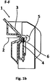
- Fig. 1 a shows a front view of a forming device 1 designed as a folding machine, which comprises a top part 3 designed as a top beam and a bottom part 4.
- a bending rail 6 is arranged, wherein - as from a in Fig. 1b illustrated sectional view according to a section line FF Fig. 1 a - it can be seen that a reshaping component 2, which is presently designed as a metal sheet, between the upper part 3 and the bending rail 6 of the lower part 4 is fixed.
- the lower part 4 As well as the bending rail 6 arranged on the lower part 4 are pivoted so far relative to the upper part 3 in accordance with a relative movement 5 marked with a double arrow, until the component has been bent in accordance with the desired bending angle or Bend radius bent and accordingly plastically deformed.
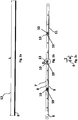
- Fig. 2a shows a plan view and Fig. 2b a front view of the bending rail 6.
- the bending rail 6 has a longitudinal extent 12 of length L and, as in a side view of the bending rail 6 in Fig. 2c is recognizable, a width B and a depth T on.
- the bending rail 6 has an at least partially an edge 7 forming first region 8 and a second region 9, wherein the bending rail 6 is arranged in the forming device 1 such that the first region 8 faces the component to be formed 2, and accordingly the edge 7th rests against the component 2.
- the bending rail 6 further comprises in the present case a plurality of deformation components 10, by means of which the first region 8 is at least partially elastically deformable.
- the bending rail 6 likewise has a slot 11 which spaces the first area 8 from the second area 9 at least over a substantial area of the longitudinal extension 12 of the bending rail 6. In other words, therefore, the slot 11 of the bending rail 6 extends over a large part of the length L of the bending rail 6.
- the deformation components 10 are arranged in respective recesses 13 of the bending rail, wherein the recesses 13 are surrounded by the first region 8 and the second region 9 , In the present case, the recesses 13 are thus arranged between the first region 8 and the second region 9.
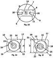
- Fig. 2d shows an enlarged view of an in Fig. 2b with D marked section, it being understood that the bending rail 6 includes respective cover plates 19.
- the Cover plates 19 serve to stabilize the bending rail 6 and allow elastic deformation by means of the respective deformation components 10 such that, although the width B (FIG. Fig. 2c ) of the bending rail 6 along its longitudinal extension 12 and thus along its length L can change, but a lateral warping between the first region 8 and the second region 9 is effectively prevented.
- cover plates 19 In order to fix the cover plates 19 particularly securely on the bending rail 6, they are presently screwed to the bending rail 6 by means of respective screws 20, which are designed as countersunk screws.
- the screws 20 are presently extending parallel to the longitudinal extent 12 and arranged on opposite sides of the respective cover plate 19.
- the bending rail 6 is present in one piece and accordingly made particularly resource-friendly.
- Fig. 2e and Fig. 2f each show an enlarged front view of the deformation component 10, wherein Fig. 2e shows a position of the deformation component 10, in which no deformation of the bending rail 6 takes place and Fig. 2f a position in which at least partially an elastic deformation of the bending rail 6 takes place.
- the deformation component 10 comprises a first component 14 and a second component 15, wherein the first component 14 and the second component 15 are formed as respective eccentric bearing shells and movable relative to each other. Between the first component 14 and the second component 15, an eccentric part 16 designed as an eccentric shaft is arranged, which has an eccentricity 17.
- Fig. 2e shows a position of the deformation component 10, in which no deformation of the bending rail 6 takes place
- Fig. 2f a position in which at least partially an elastic deformation of the bending rail 6 takes place.
- the deformation component 10 comprises a first component 14 and a second component 15, wherein the first component 14 and the second component 15 are formed as respective eccentric bearing shells and
- the eccentricity 17 runs parallel to the longitudinal extension 12 or to the slot 11 of the bending rail 6, whereby a gap 18, which is formed between the first component 14 and the second component 15, has a minimum value and, accordingly, a height of the respective deformation component 10, which by the first component 14, the second component 15 and the eccentric 16 is formed having the value h.
- the extension of the height with the value h in Fig. 2e extends in the same direction as the width B of the bending bar 6 and thus substantially perpendicular to the longitudinal extent 12.
- the eccentric 16 is rotatably mounted by means of tool engagement in an eccentric to a rotational axis 23 of the eccentric 16 and in the present case designed as a hexagon fixation opening 22 about the rotation axis 23.
- the deformation force and thus also the height change of the deformation component 10 is transferred from the value h to the value h 'on the bending rail 6.
- the bending rail 6 is deformed elastically at least in some areas, specifically at those regions of the bending rail 6 in which a change in the height of the deformation component 10 takes place.
- the first region 8 and, additionally or alternatively, the second region 9 of the bending rail 6 as a function of the relative movement between the first component 14 and the second component 15 of the deformation component 10 movable.
- the first component 14 and the second component 15 could be dispensed with and the eccentric part 16 could abut directly on the first region 8 and additionally or alternatively on the second region 9.
- the eccentric part 16 would then be in direct contact with the first region 8 and the second region 9 of the bending rail 6.
- the slot 11 and, consequently, the first area 8 of the bending bar 6 or its edge 7 would then buckle directly due to its eccentricity 17.
Description
Die Erfindung betrifft eine Umformvorrichtung zur plastischen Verformung eines Bauteils, insbesondere eines Blechbauteils gemäß dem Oberbegriff von Patentanspruch 1. Des Weiteren betrifft die Erfindung ein Verfahren zum Umformen eines Bauteils, unter Verwendung der erfindungsgemäßen Unformvorrichtung. Beim Umformen von Bauteilen, insbesondere von metallischen Halbzeugen bzw. Blechbauteilen werden bekanntermaßen - je nach Art des Umformprozesses - beispielsweise Schwenkbiegemaschinen oder Pressmaschinen zur plastischen Verformung der jeweiligen Bauteile eingesetzt. In Abhängigkeit der Materialeigenschaften, wie beispielsweise dem E-Modul oder der Härte des jeweiligen Bauteils kann dieses je nach Art des Umformverfahrens einer Druck-, Zug-, Schub-, oder Biegeumformung unterzogen werden, wobei vor allem aus einem Metall gebildete Bauteile für die eben genannten Umformverfahren besonders geeignet sind. Je nach Einsatzgebiet können als Werkstoffe für das für den Umformprozess vorgesehene Bauteil beispielsweise Stahl, Aluminium, Kupfer oder Legierungen wie Messing verwendet werden. Neben den metallischen Werkstoffen können auch andere Materialien, wie beispielsweise Kunststoffe umgeformt werden.The invention relates to a forming device for plastic deformation of a component, in particular a sheet metal component according to the preamble of
Häufig kommt es beim Biegen, bzw. beim Abkanten von Bauteilen mit relativ langen Biege- oder Abkantlinien zu Winkelabweichungen des Biegewinkels über der Länge der Biegelinie. Als Folge hoher Anpresskräfte werden jeweilige Abkantmittel, wie beispielsweise ein Oberteil oder ein Unterteil einer als Schwenkbiegemaschine ausgebildeten Umformvorrichtung beim Biegen eines Bauteils selbst geringfügig durchgebogen, wenn das Bauteil unter einer Relativbewegung zwischen dem Unterteil und dem Oberteil der Umformvorrichtung verformt wird. Ein derartiges Durchbiegen hat zur Folge, dass der Abkantwinkel entlang der Längserstreckung des gebogenen, bzw. abgekanteten Bauteils nicht konstant ist. Je nach Fertigungstoleranz kann dies also dazu führen, dass bei der Bauteilumformung vermehrt Ausschuss produziert wird oder zumindest die umgeformten Bauteile unter hohem Aufwand nachbearbeitet werden müssen. Eine derartige Nachbearbeitung bzw. ein Produzieren von Ausschuss ist insbesondere in der industriellen Fertigung hinsichtlich eines zusätzlichen Zeit- und Kostenaufwands besonders unvorteilhaft. Dementsprechend ist das Herstellen von umgeformten, bzw. gebogenen Bauteilen mit besonders hohen Toleranzanforderungen nur unter erheblichem Aufwand möglich bzw. sogar technisch nicht realisierbar.It often happens during bending, or when bending of components with relatively long bending or bending lines to angular deviations of the bending angle over the length of the bending line. As a result of high contact forces respective bending means, such as an upper part or a lower part of a forming bending bending machine forming device when bending a component itself are slightly bent when the component is deformed under a relative movement between the lower part and the upper part of the forming device. As a result of such bending, the bending angle along the longitudinal extension of the bent, or folded component is not constant. Depending on the manufacturing tolerance, this can lead to increased rejects being produced during component forming or at least the reshaped components have to be reworked at great expense. Such post-processing or production of rejects is particularly disadvantageous in industrial production in terms of additional time and expense. Accordingly, the production of formed or bent components with particularly high tolerance requirements is possible only with considerable effort or even technically unrealizable.
Aus der
Aus der
Der Werkzeugträger ist über seine Länge mit mehreren Stellelementen ausgestattet, welche von einer dem Werkstück abgewandten Seite auf das Werkzeug einwirken. Jedes Stellelement umfasst dabei einen Hydraulikzylinder, wobei die Hydraulikzylinder derart hydraulisch miteinander verbunden sind, dass sich während eines Umformvorgangs ein längs des Werkzeugs im Wesentlichen gleichförmiger Anpressdruck an einem Werkstück einstellt.The tool carrier is equipped over its length with a plurality of actuating elements which act on the tool from a side facing away from the workpiece. Each actuating element in this case comprises a hydraulic cylinder, wherein the hydraulic cylinders are hydraulically connected to each other such that during a forming process, a substantially uniform contact pressure on a workpiece is set along the tool.
Die
Es ist Aufgabe der Erfindung, eine Umformvorrichtung zur plastischen Verformung eines Bauteils, insbesondere einem Blechbauteil zu schaffen, welche kostengünstig herstellbar ist und unerwünschte Abweichungen beim Umformen des Bauteils sicher unterbindet. Des Weiteren ist es Aufgabe der vorliegenden Erfindung, ein entsprechendes Verfahren zum Umformen eines Bauteils zu schaffen.It is an object of the invention to provide a forming device for plastic deformation of a component, in particular a sheet metal component, which is inexpensive to manufacture and safely prevents unwanted deviations during forming of the component. Furthermore, it is an object of the present invention to provide a corresponding method for forming a component.
Diese Aufgabe wird durch eine Umformvorrichtung mit den Merkmalen des Patentanspruchs 1 und durch ein Verfahren zum Umformen eines Bauteils mit den Merkmalen des Patentanspruchs 8 gelöst. Vorteilhafte Ausgestaltungen mit zweckmäßigen Weiterbildungen der Erfindung sind in den abhängigen Patentansprüchen angegeben.This object is achieved by a forming device having the features of
Bei der erfindungsgemäßen Umformvorrichtung weist die Biegeschiene einen Schlitz auf, welcher den ersten Bereich von dem zweiten Bereich zumindest über einen wesentlichen Bereich einer Längserstreckung der Biegeschiene beabstandet und die Biegeschiene umfasst wenigstens eine Aussparung zwischen dem ersten Bereich und dem zweiten Bereich, in welcher die Verformungskomponente angeordnet ist.In the forming device according to the invention, the bending rail has a slot which spaces the first region from the second region over at least a substantial portion of a longitudinal extension of the bending rail and the bending rail comprises at least one recess between the first region and the second region in which the deformation component is arranged is.
Anhand der Verformungskomponente ist die Biegeschiene in sich elastisch verformbar, wobei zumindest der erste Bereich verwölbt werden kann und zusätzlich oder alternativ der zweite Bereich einer Wölbung unterworfen wird. Durch das Verwenden mehrerer Verformungskomponenten an unterschiedlichen Stellen der Biegeschiene wird ein höherer Freiheitsgrad bei der Verwölbung des ersten Bereichs der Biegeschiene und damit deren Kante geschaffen. Dadurch können auch etwaige Winkelabweichungen eines Biegewinkels ausgeglichen werden, wenn z.B. das Durchbiegen des Oberteils der Umformvorrichtung - beispielsweise in Folge asymmetrischer Versteifungsstreben bzw. Materialanhäufungen oder Materialinhomogenitäten des Ober- oder Unterteils der Umformvorrichtung bzw. des Bauteils - beim Umformen außermittig erfolgt. Durch das Verwenden mehrerer der Verformungskomponenten könnte also die Kante des ersten Bereichs der Biegeschiene nicht nur konkav oder konvex, sondern auch beispielsweise wellenförmig elastisch verformt werden, um entsprechende Abweichungen auszugleichen.Based on the deformation component, the bending rail is elastically deformable in itself, wherein at least the first region can be arched and additionally or alternatively, the second region is subjected to a curvature. By using a plurality of deformation components at different locations of the bending rail, a higher degree of freedom is created in the warping of the first region of the bending rail and thus its edge. Thereby also any angular deviations of a bending angle can be compensated, if e.g. the bending of the upper part of the forming device - for example, as a result of asymmetric stiffening struts or material accumulations or material inhomogeneities of the upper or lower part of the forming device or the component - takes place off-center during forming. By using a plurality of the deformation components, therefore, the edge of the first region of the bending rail could not only be concave or convex, but also, for example, wave-shaped elastically deformed in order to compensate for corresponding deviations.
Anders als aus dem Stand der Technik bekannt, ist also die Biegeschiene, dadurch dass sie wenigstens die eine Verformungskomponente umfasst und somit in sich selbst bereichsweise elastisch verformbar ist, als sogenannte bombierbare Biegeschiene ausgebildet. Ist das umzuformende Bauteil beispielsweise als Blech ausgebildet, so kann mittels der bombierbaren Biegeschiene ein jeweils unterschiedliches Rückfederverhalten des gebogenen Bleches über die gesamte Arbeitsbreite der Umformvorrichtung bzw. die Länge der Biegeschiene ausgeglichen werden. Da es sich bei der Biegeschiene um ein besonders preiswert und einfach zu fertigendes Bauteil der Umformvorrichtung handelt, wird dementsprechend auch eine besonders wirtschaftliche Möglichkeit geschaffen, Abweichungen entlang der Biegelinie zu kompensieren.Unlike the prior art, therefore, the bending rail, characterized in that it comprises at least one deformation component and thus in itself is partially elastically deformable, formed as a so-called barbed bending rail. If the component to be formed is designed, for example, as a metal sheet, a respective different springback behavior of the bent metal sheet over the entire working width of the shaping device or the length of the bending rail can be compensated by means of the bightable bending rail. Since it is a particularly inexpensive and easy to manufacture component of the forming device in the bending rail, a particularly economical way is also created to compensate for deviations along the bending line.
Durch den Schlitz in der Biegeschiene wird gezielt eine Inhomogenität bezüglich deren Festigkeit und Steifigkeit in dieser geschaffen und die mittels der Verformungskomponenten ausgeübte Verformung der Biegeschiene besonders wirksam in Form einer Verwölbung der Kante umgesetzt. Einerseits ist es in diesem Zusammenhang denkbar mittels der Verformungskomponente den Schlitz zumindest bereichsweise aufzuweiten und dadurch eine Verformung des ersten Bereichs gegenüber dem zweiten Bereich zu bewirken. Andererseits ist es mittels des Schlitzes ebenfalls möglich, den zweiten Bereich lediglich als Zugkraft bzw. Druckkraft übertragendes Element einzusetzen, welches an dem Unterteil derart über dessen Länge fixiert wird, dass der zweite Bereich selbst nicht elastisch gebogen, sondern lediglich gestreckt oder gestaucht wird. Der Schlitz wird dann dabei bereichsweise aufgeweitet. Eine derartige Verformung der Biegeschiene bzw. deren Kante kann dementsprechend dann besonders wirksam erfolgen, wenn der erste Bereich und der zweite Bereich der Biegeschiene an deren beiden Enden entsprechend der Längserstreckung miteinander verbunden sind und sich somit der Schlitz über einen wesentlichen Bereich der Biegeschiene erstreckt.Through the slot in the bending bar an inhomogeneity with respect to their strength and rigidity is specifically created in this and implemented by means of the deformation components deformation of the bending rail particularly effective in the form of a warping of the edge. On the one hand, in this context, it is conceivable to widen the slot at least in regions by means of the deformation component and thereby to effect a deformation of the first region relative to the second region. On the other hand, it is also possible by means of the slot to use the second region only as a tensile force or compressive force transmitting element which is fixed to the lower part over its length such that the second region itself is not elastically bent, but only stretched or is compressed. The slot is then widened in some areas. Such a deformation of the bending rail or its edge can accordingly take place particularly effectively if the first region and the second region of the bending rail are connected together at their two ends corresponding to the longitudinal extension and thus the slot extends over a substantial region of the bending rail.
Durch das Anordnen der Verformungskomponenten in der Aussparung kann die Biegeschiene besonders kompakt ausgebildet werden. Durch eine derartige Anordnung kann die Biegeschiene zudem besonders bauraumsparend ausgeführt werden. Durch eine entsprechende Konturgebung der Aussparung kann die elastische Verformbarkeit der Biegeschiene beeinflusst werden. Wird die Aussparung großzügig dimensioniert und dementsprechend viel Material aus der Biegeschiene entfernt, so verringert sich der Abstand zwischen dem Rand der Aussparung und der Kante der Biegeschiene. Somit kann eine stärkere Verformung der Biegeschiene ermöglicht werden, bzw. wird für eine Verformung der Biegeschiene weniger Kraft benötigt. Wird hingegen die Aussparung besonders klein dimensioniert, so verbleibt mehr Material im Bereich zwischen der Kante und der Aussparung an der Biegeschiene, wodurch diese besonders steif und widerstandsfähig gegenüber einer Krafteinwirkung von Seiten des Bauteils ist, wenn dieses verformt wird. Somit wird auf besonders einfache Art und Weise eine effiziente und wirtschaftliche Möglichkeit geschaffen, die Kante der Biegeschiene den jeweiligen Erfordernissen entsprechend zu verwölben.By arranging the deformation components in the recess, the bending rail can be made particularly compact. By such an arrangement, the bending rail can also be designed to save space. By a corresponding contouring of the recess, the elastic deformability of the bending rail can be influenced. If the recess is generously dimensioned and correspondingly much material is removed from the bending rail, the distance between the edge of the recess and the edge of the bending rail is reduced. Thus, a greater deformation of the bending rail can be made possible, or less force is required for a deformation of the bending rail. If, on the other hand, the recess is dimensioned to be particularly small, more material remains in the area between the edge and the recess on the bending rail, which makes it particularly stiff and resistant to a force acting on the component side when it is deformed. Thus, an efficient and economical way is created in a particularly simple manner to buckle the edge of the bending rail according to the respective requirements.
Als weiter vorteilhaft hat es sich gezeigt, wenn die Verformungskomponente eine erste Komponente und eine zweiten Komponente umfasst, welche relativ zueinander bewegbar sind. Durch den Einsatz der ersten Komponente und der zweiten Komponenten können etwaige unerwünschte plastische Verformungen an der Biegeschiene besonders wirksam unterbunden werden, insbesondere sofern die erste Komponente und die zweite Komponente als druckverteilende Schalenelemente ausgebildet sind. Die erste Komponente und die zweite Komponente werden unter Ausübung eines Druckes auseinander bewegt und dadurch die Verformung der Biegeschiene erwirkt. Der durch die Verformungskomponente ausgeübte und die Biegeschiene bereichsweise elastisch verformende Druck wird dann mittels der ersten Komponente und der zweiten Komponente besonders gleichmäßig auf die Biegeschiene verteilt, wodurch elastische Verformungen an der Biegeschiene in Folge von unzulässig hohen Druckspitzen besonders wirksam unterbunden werden können.As a further advantage, it has been shown that the deformation component comprises a first component and a second component, which are movable relative to each other. By using the first component and the second components, any undesired plastic deformations on the bending rail can be prevented in a particularly effective manner, in particular if the first component and the second component are designed as pressure-distributing shell elements. The first component and the second component are moved apart by applying a pressure, thereby causing the deformation of the bending rail. The pressure exerted by the deformation component and the bending rail partially elastically deforming pressure is then distributed by the first component and the second component particularly evenly on the bending rail, whereby elastic deformation of the bending rail due to impermissibly high pressure peaks can be particularly effectively prevented.
Dies gilt insbesondere, wenn gemäß einer weiteren vorteilhaften Ausgestaltung die erste Komponente und die zweite Komponente der Verformungskomponente mittels eines Exzenterteils relativ zueinander bewegbar sind. Durch ein Verdrehen des Exzenterteils, welches zwischen der ersten Komponente und der zweiten Komponente angeordnet ist, ist die Verformungskomponente stufenlos verstellbar und dementsprechend die elastische Verformung der Biegeschiene besonders exakt justierbar. In Abhängigkeit einer Exzentrizität des Exzenterteils sind die erste und zweite Komponente unter Ausübung einer besonders hohen Verformungskraft bzw. unter Zurücklegen eines besonders großen Verformungsweges relativ zueinander bewegbar.This applies in particular if, according to a further advantageous embodiment, the first component and the second component of the deformation component are movable relative to one another by means of an eccentric part. By rotating the eccentric part, which is arranged between the first component and the second component, the deformation component is infinitely adjustable and, accordingly, the elastic deformation of the bending rail can be adjusted particularly precisely. Depending on an eccentricity of the eccentric part, the first and second components can be moved relative to each other by exerting a particularly high deformation force or by traversing a particularly large deformation path.
Von Vorteil ist weiterhin, wenn der erste Bereich und/oder der zweite Bereich der Biegeschiene in Abhängigkeit von der relativen Bewegung zwischen der ersten Komponente und der zweiten Komponente der Verformungskomponente bewegbar ist. Eine elastische Verformung der Biegeschiene ist dementsprechend dann besonders intuitiv durch die Umformvorrichtung bedienendes Personal möglich, wenn mit einer Relativbewegung der ersten Komponente zur zweiten Komponenten der Verformungskomponente auch eine elastische Verformung der Biegeschiene einhergeht. Dies gilt insbesondere dann, wenn bei einer Vergrößerung des Abstands zwischen der ersten Komponente und der zweiten Komponente auch eine stärkere elastische Verformung der Biegeschiene erfolgt, wodurch aus ergonomischer Sicht eine besonders intuitive Bedienung der Umformvorrichtung ermöglicht wird.It is furthermore advantageous if the first region and / or the second region of the bending rail is movable as a function of the relative movement between the first component and the second component of the deformation component. An elastic deformation of the bending bar is correspondingly particularly intuitive by the forming device operating personnel possible if associated with a relative movement of the first component to the second components of the deformation component and an elastic deformation of the bending bar. This applies in particular when, with an increase in the distance between the first component and the second component, a greater elastic deformation of the bending rail takes place, whereby ergonomically speaking, a particularly intuitive operation of the forming device is made possible.
In einer weiteren vorteilhaften Ausgestaltung der Erfindung ist die Biegeschiene einteilig ausgebildet. Da die Fertigungskosten insbesondere von Präzisionsbauteilen mit der Anzahl der Einzelkomponenten, aus denen das jeweilige Bauteil zusammengesetzt ist, ansteigen, ist eine einteilige Ausführung der Biegeschiene besonders ressourcenschonend.In a further advantageous embodiment of the invention, the bending rail is integrally formed. Since the production costs, in particular of precision components increase with the number of individual components of which the respective component is composed, a one-piece design of the bending rail is particularly resource-friendly.
Bevorzugt umfasst die Biegeschiene jeweilige Abdeckbleche zur geführten Relativbewegung zwischen dem ersten und dem zweiten Bereich. Mittels derartiger Abdeckbleche kann besonders effizient ein etwaiges seitliches Verbiegen des ersten Bereichs relativ zu dem zweiten Bereich bzw. umgekehrt unterbunden werden. Mit anderen Worten kann mittels der Abdeckbleche also eine besonders exakte und im Wesentlichen in einer Ebene verlaufenden Bewegung zwischen dem ersten Bereich und dem zweiten Bereich realisiert werden. Eine Verwölbung der Biegeschiene in eine unerwünschte Raumrichtung wird dementsprechend besonders wirksam unterbunden. Schließlich ist es von Vorteil, wenn die Umformvorrichtung als Schwenkbiegemaschine ausgebildet ist. Schwenkbiegemaschinen sind besonders geeignet um Bauteile, welche als Metallbleche mit großen Dicken ausgebildet sind, mit großer Präzision umzuformen. Die Biegeschiene kann besonders aufwandsarm auf die Steifigkeit der Schwenkbiegemaschine angepasst werden und dementsprechend auch Abweichungen einer langen Biegelinie besonders wirksam kompensieren.Preferably, the bending rail comprises respective cover plates for guided relative movement between the first and the second region. By means of such cover plates can be particularly efficient prevented any lateral bending of the first region relative to the second region or vice versa. In other words, by means of the cover plates, therefore, a particularly exact movement, which essentially extends in one plane, can be realized between the first region and the second region. A warping of the bending rail in an undesired spatial direction is accordingly particularly effectively prevented. Finally, it is advantageous if the forming device is designed as a folding machine. Swivel bending machines are particularly suitable for reshaping components which are designed as metal sheets with large thicknesses with great precision. The bending bar can be adapted to the rigidity of the pivoting bending machine with particularly little effort and, accordingly, can compensate deviations of a long bending line particularly effectively.
Bei dem erfindungsgemäßen Verfahren zum Umformen eines Bauteils mittels einer ein Oberteil und ein Unterteil umfassenden Umformvorrichtung, bei welcher das Bauteil zwischen dem Oberteil und einer dem Unterteil zugeordneten Biegeschiene fixiert und unter einer Relativbewegung zwischen dem Unterteil und dem Oberteil der Umformvorrichtung verformt wird, erfolgt ein Einstellen jeweiliger vordefinierter Verformungsparameter mittels mindestens einer Verformungskomponente. Mittels der Verformungskomponente wird wenigstens ein dem Bauteil zugewandter und zumindest bereichsweise eine Kante ausbildender erster Bereich einer den ersten Bereich sowie einen zweiten Bereich aufweisenden Biegeschiene wenigstens bereichsweise elastisch verformt. Das Umformen des Bauteils erfolgt unter der Relativbewegung zwischen dem Unterteil und dem Oberteil der Umformvorrichtung durch Ausüben einer Verformungskraft unter Vermittlung der Biegeschiene. Ein derartiges Verfahren stellt eine besonders exakte und einfache Umformung des Bauteils sicher. Es lassen sich somit vordefinierte, also gewünschte Verformungsparameter besonders genau einstellen. Zur Durchführung des Verfahrens wird eine erfindungsgemäße Umformvorrichtung verwendet.In the method according to the invention for forming a component by means of a forming device comprising a top part and a bottom part, in which the component is fixed between the upper part and a bending rail assigned to the lower part and deformed under a relative movement between the lower part and the upper part of the shaping device, an adjustment takes place respective predefined deformation parameters by means of at least one deformation component. By means of the deformation component at least one of the component facing and at least partially an edge forming first region of a first region and a second region having bending rail is elastically deformed at least partially. The forming of the component takes place under the relative movement between the lower part and the upper part of the shaping device by exerting a deformation force by the intermediary of the bending rail. Such a method ensures a particularly accurate and simple deformation of the component. Predefined, that is to say desired deformation parameters can therefore be set particularly precisely. For carrying out the method, a forming device according to the invention is used.
In einer vorteilhaften Ausgestaltung der Erfindung wird die Biegeschiene in Abhängigkeit jeweiliger Geometriegrößen des Bauteils mittels der Verformungskomponente elastisch verformt. Zu derartigen Geometriegrößen gehören beispielsweise die Länge, die Breite oder die Tiefe an der Stelle des Bauteils, an welcher die Umformung erfolgen soll. Die Verformung des Bauteils, bzw. die Eignung des Bauteils für eine leichte oder erhebliche Umformung hängt also von derartigen Dimensionen ab, wobei beispielsweise die Tiefe, also die Materialstärke des Bauteils den maximal möglichen Biegeradius bzw. den Biegewinkel beeinflusst. Erstreckt sich das umzuformende Bauteil lediglich über einen kurzen Bereich der Längserstreckung der Biegeschiene, so werden die Klemmmittel, also das Oberteil und zusätzlich oder alternativ das Unterteil der Umformvorrichtung lokal besonders stark beansprucht und gegebenenfalls bei der Bauteilumformung selbst elastisch verformt. Dies kann durch die Bombierung, also die elastische Verformung der Biegeschiene wirksam ausgeglichen werden.In an advantageous embodiment of the invention, the bending rail is elastically deformed in dependence of respective geometry sizes of the component by means of the deformation component. Such geometry sizes include, for example, the length, the width or the depth at the location of the component at which the transformation is to take place. The deformation of the component, or the suitability of the component for a slight or substantial deformation thus depends on such dimensions, for example, the depth, so the material thickness of the component influences the maximum possible bending radius or the bending angle. If the component to be formed extends only over a short region of the longitudinal extent of the bending rail, then the clamping means, ie the upper part and, additionally or alternatively, the lower part of the shaping device, are subjected to particularly high local stress locally and, if necessary, during the component deformation itself elastically deformed. This can be effectively compensated by the crowning, so the elastic deformation of the bending rail.
Schließlich ist es von Vorteil, wenn die Biegeschiene in Abhängigkeit jeweiliger, die Festigkeit des Bauteils betreffender Parameter mittels der Verformungskomponente elastisch verformt wird. Zur Festigkeit des Bauteils gehören insbesondere Materialeigenschaften, welche den Umformprozess beeinflussen. Zu derartigen Materialeigenschaften gehört beispielsweise der E-Modul oder die Kerbschlagzähigkeit des Bauteils. Weitere Parameter, welche die Festigkeit des Bauteils betreffen, sind beispielsweise die Konzentration von Legierungsbestandteilen oder ein etwaiges Härteverfahren, welchem das Bauteil unterworfen worden ist bzw. eine bestimmte Einhärttiefe, die bei dem entsprechenden Härteverfahren des umzuformenden Bauteils zuvor gewählt wurde.Finally, it is advantageous if the bending bar is elastically deformed by means of the deformation component as a function of respective parameters relating to the strength of the component. The strength of the component includes in particular material properties that influence the forming process. Such material properties include, for example, the modulus of elasticity or notched impact strength of the component. Further parameters which relate to the strength of the component are, for example, the concentration of alloy constituents or a possible hardening process to which the component has been subjected or a specific hardening depth which was previously selected in the corresponding hardening process of the component to be formed.
Die für die erfindungsgemäße Umformvorrichtung beschriebenen Vorteile und bevorzugten Ausführungsformen gelten auch für das erfindungsgemäße Verfahren und umgekehrt. Zur Durchführung des erfindungsgemäßen Verfahrens kann die erfindungsgemäße Vorrichtung verwendet werden.The advantages and preferred embodiments described for the forming device according to the invention also apply to the method according to the invention and vice versa. For carrying out the method according to the invention, the device according to the invention can be used.
Weitere Vorteile, Merkmale und Einzelheiten der Erfindung ergeben sich aus den Ansprüchen, der nachfolgenden Beschreibung bevorzugter Ausführungsformen sowie anhand der Zeichnungen.Further advantages, features and details of the invention will become apparent from the claims, the following description of preferred embodiments and from the drawings.
Es zeigen:
- Fig. 1a
- eine Vorderansicht einer als Schwenkbiegemaschine ausgebildeten Umformvorrichtung, welche ein Oberteil sowie ein eine bombierbare Biegeschiene umfassendes Unterteil umfasst;
- Fig. 1b
- eine Schnittansicht der in
Fig. 1 a gezeigten Umformvorrichtung entsprechend einer inFig. 1 a gekennzeichneten Schnittlinie F-F; - Fig. 2a
- eine Draufsicht auf die Biegeschiene der Umformvorrichtung;
- Fig. 2b
- eine Vorderansicht auf die Biegeschiene der Umformvorrichtung;
- Fig. 2c
- eine Seitenansicht auf die Biegeschiene der Umformvorrichtung;
- Fig. 2d
- eine Detailansicht eines in
Fig. 2 mit D gekennzeichneten Ausschnitts, welcher ein Abdeckblech zeigt, mittels welchem ein erster Bereich und ein zweiter Bereich der Biegeschiene geführt werden; - Fig. 2e
- eine vergrößerte Vorderansicht einer Verformungskomponente der Biegeschiene, wobei die Verformungskomponente vorliegend ein als Exzenterwelle ausgebildetes Exzenterteil umfasst, mittels welchem eine ersten Komponente und eine zweiten Komponente der Verformungskomponente relativ zu einander verstellbar sind; und in
- Fig. 2f
- eine vergrößerte Vorderansicht auf die Verformungskomponente, deren erste Komponente und zweite Komponente in Folge einer Verdrehung des Exzenterteils voneinander beabstandet werden.
- Fig. 1a
- a front view of a formed as a bending machine forming device comprising an upper part and a bombable bending rail comprehensive base;
- Fig. 1b
- a sectional view of in
Fig. 1 a shown forming device according to a inFig. 1 a marked section line FF; - Fig. 2a
- a plan view of the bending rail of the forming device;
- Fig. 2b
- a front view of the bending rail of the forming device;
- Fig. 2c
- a side view of the bending rail of the forming device;
- Fig. 2d
- a detailed view of an in
Fig. 2 D section marked D, which shows a cover plate, by means of which a first region and a second region of the bending rail are guided; - Fig. 2e
- an enlarged front view of a deformation component of the bending rail, wherein the deformation component in the present case comprises an eccentric shaft designed as an eccentric shaft, by means of which a first component and a second component of the deformation component are adjustable relative to each other; and in
- Fig. 2f
- an enlarged front view of the deformation component, the first component and second component due to a rotation of the eccentric are spaced apart.
Wie insbesondere aus
Es ist klar, dass alternativ auch auf die erste Komponente 14 und die zweite Komponente 15 verzichtet werden könnte und das Exzenterteil 16 direkt an dem ersten Bereich 8 und zusätzlich oder alternativ an dem zweiten Bereich 9 anliegen könnte. Mit anderen Worten würde dann das Exzenterteil 16 direkt mit dem ersten Bereich 8 und dem zweiten Bereich 9 der Biegeschiene 6 in Kontakt stehen. Durch Verdrehen des Exzenterteils 16 würde dann aufgrund dessen Exzentrizität 17 direkt der Schlitz 11 und infolgedessen der erste Bereich 8 der Biegeschiene 6 bzw. deren Kante 7 verwölbt.It is clear that, alternatively, the
Claims (10)
- Forming device (1) for plastically deforming a structural element (2), in particular a sheet metal structural element, which is fixable between a top part (3) and a bottom part (4) comprising a bending rail (6) of the forming device (1) and is deformable by a relative movement (5) between the bottom part (4) and the top part (3) of the forming device (1), wherein the bending rail (6) includes at least a first area (8) facing the structural element (2) and forming an edge (7) at least in certain areas as well as a second area (9) and in addition at least one deforming component (10), by means of which at least the first area (8) is elastically deformable at least in certain areas,
characterized in that
the bending rail (6) has a slit (11), which spaces the first area (8) from the second area (9) at least over a substantial area of a longitudinal extension (12) of the bending rail (6), and the bending rail (6) includes at least one recess (13) between the first area (8) and the second area (9), in which the deforming component (10) is disposed. - Forming device (1) according to claim 1,
characterized in that
the deforming component (10) includes a first component (14) and a second component (15), which are movable relatively to each other. - Forming device (1) according to claim 2,
characterized in that
the first component (14) and the second component (15) of the deforming component (10) are movable relatively to each other by means of an eccentric part (16). - Forming device (1) according to any one of claims 2 or 3,
characterized in that
the first area (8) and/or the second area (9) of the bending rail (6) are movable depending on the relative movement between the first component (14) and the second component (15) of the deforming component (10). - Forming device (1) according to any one of the preceding claims,
characterized in that
the bending rail (6) is integrally formed. - Forming device (1) according to any one of the preceding claims,
characterized in that
the bending rail (6) includes respective cover sheets (19) for guided relative movement between the first area (8) and the second area (9). - Forming device (1) according to any one of the preceding claims,
characterized in that
the forming device (1) is formed as a swing-bending machine. - Method for forming a structural element (2) by means of a forming device (1) comprising a top part (3) and a bottom part (4), in which the structural element (2) is fixed between the top part (3) and a bending rail (6) associated with the bottom part (4) and is deformed by a relative movement (5) between the bottom part (4) and the top part (3) of the forming device (1),
characterized by the following steps:- adjusting respective predefined deforming parameters by means of at least one deforming component (10), by means of which at least a first area (8) facing the structural element (2) and forming an edge (7) at least in certain areas of a bending rail (6) having the first area (8) as well as a second area (9) is elastically deformed at least in certain areas; and- forming the structural element (2) by the relative movement (5) between the bottom part (4) and the top part (3) of the forming device (1) by exerting a deforming force with intervention of the bending rail (6), wherein- for performing the method, a forming device (1) according to any one of claims 1 to 7 is used. - Method according to claim 8,
characterized in that
the bending rail (6) is elastically deformed by means of the deforming component (10) depending on respective geometric variables of the structural element (2). - Method according to claim 8,
characterized in that
the bending rail (6) is elastically deformed by means of the deforming component (10) depending on respective parameters relating to the strength of the structural element (2).
Priority Applications (1)
| Application Number | Priority Date | Filing Date | Title |
|---|---|---|---|
| EP13192503.4A EP2871005B1 (en) | 2013-11-12 | 2013-11-12 | Forming device for the plastic deformation of a component and method for forming a component |
Applications Claiming Priority (1)
| Application Number | Priority Date | Filing Date | Title |
|---|---|---|---|
| EP13192503.4A EP2871005B1 (en) | 2013-11-12 | 2013-11-12 | Forming device for the plastic deformation of a component and method for forming a component |
Publications (2)
| Publication Number | Publication Date |
|---|---|
| EP2871005A1 EP2871005A1 (en) | 2015-05-13 |
| EP2871005B1 true EP2871005B1 (en) | 2016-05-25 |
Family
ID=49641487
Family Applications (1)
| Application Number | Title | Priority Date | Filing Date |
|---|---|---|---|
| EP13192503.4A Active EP2871005B1 (en) | 2013-11-12 | 2013-11-12 | Forming device for the plastic deformation of a component and method for forming a component |
Country Status (1)
| Country | Link |
|---|---|
| EP (1) | EP2871005B1 (en) |
Family Cites Families (5)
| Publication number | Priority date | Publication date | Assignee | Title |
|---|---|---|---|---|
| DE19735793C2 (en) * | 1997-08-18 | 2001-07-12 | Wolfram Hochstrate | Folding machine |
| DE19736987A1 (en) * | 1997-08-26 | 1999-03-11 | Reinhardt Gmbh Maschbau | Bending machine |
| DE102005018866B3 (en) | 2005-04-22 | 2006-05-24 | Schechtl Maschinenbau Gmbh | Bending device e.g. for bending or beveling item such as sheet metal component, wedges article which can be worked on and movable bending mechanism is provided which is two-pieced |
| DE102006047108B4 (en) * | 2006-09-27 | 2009-09-10 | Ras Reinhardt Maschinenbau Gmbh | Bending machine for bending flat material |
| DE102008025351A1 (en) * | 2008-05-27 | 2009-12-03 | Hans Schröder Maschinenbau GmbH | forming machine |
-
2013
- 2013-11-12 EP EP13192503.4A patent/EP2871005B1/en active Active
Also Published As
| Publication number | Publication date |
|---|---|
| EP2871005A1 (en) | 2015-05-13 |
Similar Documents
| Publication | Publication Date | Title |
|---|---|---|
| EP2712702B1 (en) | Belt finishing device, belt finishing system and method for producing a belt finishing device | |
| EP3052256B1 (en) | Bending press and bending method | |
| DE102012108280A1 (en) | Bending device | |
| DE102007012316B4 (en) | Method and bending press for bending the edge strips of a planar sheet to be formed into a slotted pipe | |
| EP2077166B1 (en) | Longitudinal edge machining device for sheet metal | |
| DE19839614B4 (en) | Metal strip bending roll method for producing a tube to be welded electrically from a flat metal strip | |
| EP3263241B1 (en) | Rolling folding device and method for folding an edge section of a sheet metal part | |
| DE102007062104B4 (en) | Apparatus for a rollformer for profiling a sheet metal strip and associated method | |
| EP2871005B1 (en) | Forming device for the plastic deformation of a component and method for forming a component | |
| DE102008046160B4 (en) | Roll forming tool for roll forming sheet metal strip, as well as apparatus for roll forming of sheet metal strip | |
| EP1495816A1 (en) | Bending tool with adjustable workpiece contrasting segments as well as bending machine comprising such a bending tool | |
| DE3709018C2 (en) | Device for bending sheet metal | |
| EP2435198B1 (en) | Flexible hold-down device for roll-forming installations | |
| DE10011382A1 (en) | Bending method for e.g. hollow extruded profile of aluminum alloy with pressure application to flange in direction at right angles to profile direction | |
| DE19735793C2 (en) | Folding machine | |
| EP1372877B1 (en) | Method for extrusion and extrusion plant, in particular for production of bent extruded products | |
| WO2016071161A1 (en) | Pipe bending press | |
| CH716075A1 (en) | Fixed comb holder for a combing machine. | |
| DE202004020654U1 (en) | Folding bending press esp. for sheet metal profiles e.g. shelf boards has hold- down strips of different lengths on rotating roller above bending table, for easy adjustment to different profile widths | |
| EP2620306A2 (en) | Hinge reinforcement device for a vehicle door | |
| DE102012018169B4 (en) | Device for advancing and bending metal profiles | |
| DE102020106664B4 (en) | Method and device for bending profiles with variable cross-sections | |
| EP4186613B1 (en) | Shaping jaw of a round kneading device for forming a plastically deformable workpiece and round kneading tool with shaping jaws | |
| EP0894032A1 (en) | Device for shaping workpieces | |
| EP3147041B1 (en) | Method and device for bending a metallic semi-finished product |
Legal Events
| Date | Code | Title | Description |
|---|---|---|---|
| PUAI | Public reference made under article 153(3) epc to a published international application that has entered the european phase |
Free format text: ORIGINAL CODE: 0009012 |
|
| 17P | Request for examination filed |
Effective date: 20131112 |
|
| AK | Designated contracting states |
Kind code of ref document: A1 Designated state(s): AL AT BE BG CH CY CZ DE DK EE ES FI FR GB GR HR HU IE IS IT LI LT LU LV MC MK MT NL NO PL PT RO RS SE SI SK SM TR |
|
| AX | Request for extension of the european patent |
Extension state: BA ME |
|
| R17P | Request for examination filed (corrected) |
Effective date: 20151109 |
|
| RBV | Designated contracting states (corrected) |
Designated state(s): AL AT BE BG CH CY CZ DE DK EE ES FI FR GB GR HR HU IE IS IT LI LT LU LV MC MK MT NL NO PL PT RO RS SE SI SK SM TR |
|
| GRAP | Despatch of communication of intention to grant a patent |
Free format text: ORIGINAL CODE: EPIDOSNIGR1 |
|
| RIC1 | Information provided on ipc code assigned before grant |
Ipc: B21D 5/04 20060101AFI20151130BHEP |
|
| INTG | Intention to grant announced |
Effective date: 20151223 |
|
| GRAS | Grant fee paid |
Free format text: ORIGINAL CODE: EPIDOSNIGR3 |
|
| GRAA | (expected) grant |
Free format text: ORIGINAL CODE: 0009210 |
|
| AK | Designated contracting states |
Kind code of ref document: B1 Designated state(s): AL AT BE BG CH CY CZ DE DK EE ES FI FR GB GR HR HU IE IS IT LI LT LU LV MC MK MT NL NO PL PT RO RS SE SI SK SM TR |
|
| REG | Reference to a national code |
Ref country code: GB Ref legal event code: FG4D Free format text: NOT ENGLISH |
|
| REG | Reference to a national code |
Ref country code: CH Ref legal event code: EP |
|
| REG | Reference to a national code |
Ref country code: IE Ref legal event code: FG4D Free format text: LANGUAGE OF EP DOCUMENT: GERMAN Ref country code: AT Ref legal event code: REF Ref document number: 801829 Country of ref document: AT Kind code of ref document: T Effective date: 20160615 |
|
| REG | Reference to a national code |
Ref country code: DE Ref legal event code: R096 Ref document number: 502013003124 Country of ref document: DE |
|
| REG | Reference to a national code |
Ref country code: CH Ref legal event code: NV Representative=s name: KELLER AND PARTNER PATENTANWAELTE AG, CH |
|
| REG | Reference to a national code |
Ref country code: LT Ref legal event code: MG4D |
|
| REG | Reference to a national code |
Ref country code: NL Ref legal event code: MP Effective date: 20160525 |
|
| PG25 | Lapsed in a contracting state [announced via postgrant information from national office to epo] |
Ref country code: NL Free format text: LAPSE BECAUSE OF FAILURE TO SUBMIT A TRANSLATION OF THE DESCRIPTION OR TO PAY THE FEE WITHIN THE PRESCRIBED TIME-LIMIT Effective date: 20160525 Ref country code: FI Free format text: LAPSE BECAUSE OF FAILURE TO SUBMIT A TRANSLATION OF THE DESCRIPTION OR TO PAY THE FEE WITHIN THE PRESCRIBED TIME-LIMIT Effective date: 20160525 Ref country code: NO Free format text: LAPSE BECAUSE OF FAILURE TO SUBMIT A TRANSLATION OF THE DESCRIPTION OR TO PAY THE FEE WITHIN THE PRESCRIBED TIME-LIMIT Effective date: 20160825 Ref country code: LT Free format text: LAPSE BECAUSE OF FAILURE TO SUBMIT A TRANSLATION OF THE DESCRIPTION OR TO PAY THE FEE WITHIN THE PRESCRIBED TIME-LIMIT Effective date: 20160525 |
|
| PG25 | Lapsed in a contracting state [announced via postgrant information from national office to epo] |
Ref country code: GR Free format text: LAPSE BECAUSE OF FAILURE TO SUBMIT A TRANSLATION OF THE DESCRIPTION OR TO PAY THE FEE WITHIN THE PRESCRIBED TIME-LIMIT Effective date: 20160826 Ref country code: ES Free format text: LAPSE BECAUSE OF FAILURE TO SUBMIT A TRANSLATION OF THE DESCRIPTION OR TO PAY THE FEE WITHIN THE PRESCRIBED TIME-LIMIT Effective date: 20160525 Ref country code: PT Free format text: LAPSE BECAUSE OF FAILURE TO SUBMIT A TRANSLATION OF THE DESCRIPTION OR TO PAY THE FEE WITHIN THE PRESCRIBED TIME-LIMIT Effective date: 20160926 Ref country code: SE Free format text: LAPSE BECAUSE OF FAILURE TO SUBMIT A TRANSLATION OF THE DESCRIPTION OR TO PAY THE FEE WITHIN THE PRESCRIBED TIME-LIMIT Effective date: 20160525 Ref country code: LV Free format text: LAPSE BECAUSE OF FAILURE TO SUBMIT A TRANSLATION OF THE DESCRIPTION OR TO PAY THE FEE WITHIN THE PRESCRIBED TIME-LIMIT Effective date: 20160525 Ref country code: RS Free format text: LAPSE BECAUSE OF FAILURE TO SUBMIT A TRANSLATION OF THE DESCRIPTION OR TO PAY THE FEE WITHIN THE PRESCRIBED TIME-LIMIT Effective date: 20160525 |
|
| PG25 | Lapsed in a contracting state [announced via postgrant information from national office to epo] |
Ref country code: IT Free format text: LAPSE BECAUSE OF FAILURE TO SUBMIT A TRANSLATION OF THE DESCRIPTION OR TO PAY THE FEE WITHIN THE PRESCRIBED TIME-LIMIT Effective date: 20160525 |
|
| PG25 | Lapsed in a contracting state [announced via postgrant information from national office to epo] |
Ref country code: EE Free format text: LAPSE BECAUSE OF FAILURE TO SUBMIT A TRANSLATION OF THE DESCRIPTION OR TO PAY THE FEE WITHIN THE PRESCRIBED TIME-LIMIT Effective date: 20160525 Ref country code: CZ Free format text: LAPSE BECAUSE OF FAILURE TO SUBMIT A TRANSLATION OF THE DESCRIPTION OR TO PAY THE FEE WITHIN THE PRESCRIBED TIME-LIMIT Effective date: 20160525 Ref country code: DK Free format text: LAPSE BECAUSE OF FAILURE TO SUBMIT A TRANSLATION OF THE DESCRIPTION OR TO PAY THE FEE WITHIN THE PRESCRIBED TIME-LIMIT Effective date: 20160525 Ref country code: SK Free format text: LAPSE BECAUSE OF FAILURE TO SUBMIT A TRANSLATION OF THE DESCRIPTION OR TO PAY THE FEE WITHIN THE PRESCRIBED TIME-LIMIT Effective date: 20160525 Ref country code: RO Free format text: LAPSE BECAUSE OF FAILURE TO SUBMIT A TRANSLATION OF THE DESCRIPTION OR TO PAY THE FEE WITHIN THE PRESCRIBED TIME-LIMIT Effective date: 20160525 |
|
| PG25 | Lapsed in a contracting state [announced via postgrant information from national office to epo] |
Ref country code: SM Free format text: LAPSE BECAUSE OF FAILURE TO SUBMIT A TRANSLATION OF THE DESCRIPTION OR TO PAY THE FEE WITHIN THE PRESCRIBED TIME-LIMIT Effective date: 20160525 Ref country code: PL Free format text: LAPSE BECAUSE OF FAILURE TO SUBMIT A TRANSLATION OF THE DESCRIPTION OR TO PAY THE FEE WITHIN THE PRESCRIBED TIME-LIMIT Effective date: 20160525 Ref country code: BE Free format text: LAPSE BECAUSE OF NON-PAYMENT OF DUE FEES Effective date: 20161130 |
|
| REG | Reference to a national code |
Ref country code: DE Ref legal event code: R097 Ref document number: 502013003124 Country of ref document: DE |
|
| PLBE | No opposition filed within time limit |
Free format text: ORIGINAL CODE: 0009261 |
|
| STAA | Information on the status of an ep patent application or granted ep patent |
Free format text: STATUS: NO OPPOSITION FILED WITHIN TIME LIMIT |
|
| 26N | No opposition filed |
Effective date: 20170228 |
|
| PG25 | Lapsed in a contracting state [announced via postgrant information from national office to epo] |
Ref country code: SI Free format text: LAPSE BECAUSE OF FAILURE TO SUBMIT A TRANSLATION OF THE DESCRIPTION OR TO PAY THE FEE WITHIN THE PRESCRIBED TIME-LIMIT Effective date: 20160525 |
|
| REG | Reference to a national code |
Ref country code: IE Ref legal event code: MM4A |
|
| REG | Reference to a national code |
Ref country code: FR Ref legal event code: ST Effective date: 20170731 |
|
| PG25 | Lapsed in a contracting state [announced via postgrant information from national office to epo] |
Ref country code: LU Free format text: LAPSE BECAUSE OF NON-PAYMENT OF DUE FEES Effective date: 20161130 |
|
| PG25 | Lapsed in a contracting state [announced via postgrant information from national office to epo] |
Ref country code: FR Free format text: LAPSE BECAUSE OF NON-PAYMENT OF DUE FEES Effective date: 20161130 |
|
| PG25 | Lapsed in a contracting state [announced via postgrant information from national office to epo] |
Ref country code: IE Free format text: LAPSE BECAUSE OF NON-PAYMENT OF DUE FEES Effective date: 20161112 |
|
| REG | Reference to a national code |
Ref country code: BE Ref legal event code: MM Effective date: 20161130 |
|
| PG25 | Lapsed in a contracting state [announced via postgrant information from national office to epo] |
Ref country code: HU Free format text: LAPSE BECAUSE OF FAILURE TO SUBMIT A TRANSLATION OF THE DESCRIPTION OR TO PAY THE FEE WITHIN THE PRESCRIBED TIME-LIMIT; INVALID AB INITIO Effective date: 20131112 |
|
| PG25 | Lapsed in a contracting state [announced via postgrant information from national office to epo] |
Ref country code: MC Free format text: LAPSE BECAUSE OF FAILURE TO SUBMIT A TRANSLATION OF THE DESCRIPTION OR TO PAY THE FEE WITHIN THE PRESCRIBED TIME-LIMIT Effective date: 20160525 Ref country code: HR Free format text: LAPSE BECAUSE OF FAILURE TO SUBMIT A TRANSLATION OF THE DESCRIPTION OR TO PAY THE FEE WITHIN THE PRESCRIBED TIME-LIMIT Effective date: 20160525 Ref country code: CY Free format text: LAPSE BECAUSE OF FAILURE TO SUBMIT A TRANSLATION OF THE DESCRIPTION OR TO PAY THE FEE WITHIN THE PRESCRIBED TIME-LIMIT Effective date: 20160525 Ref country code: IS Free format text: LAPSE BECAUSE OF FAILURE TO SUBMIT A TRANSLATION OF THE DESCRIPTION OR TO PAY THE FEE WITHIN THE PRESCRIBED TIME-LIMIT Effective date: 20160525 Ref country code: MK Free format text: LAPSE BECAUSE OF FAILURE TO SUBMIT A TRANSLATION OF THE DESCRIPTION OR TO PAY THE FEE WITHIN THE PRESCRIBED TIME-LIMIT Effective date: 20160525 |
|
| GBPC | Gb: european patent ceased through non-payment of renewal fee |
Effective date: 20171112 |
|
| PG25 | Lapsed in a contracting state [announced via postgrant information from national office to epo] |
Ref country code: BG Free format text: LAPSE BECAUSE OF FAILURE TO SUBMIT A TRANSLATION OF THE DESCRIPTION OR TO PAY THE FEE WITHIN THE PRESCRIBED TIME-LIMIT Effective date: 20160525 |
|
| PG25 | Lapsed in a contracting state [announced via postgrant information from national office to epo] |
Ref country code: MT Free format text: LAPSE BECAUSE OF FAILURE TO SUBMIT A TRANSLATION OF THE DESCRIPTION OR TO PAY THE FEE WITHIN THE PRESCRIBED TIME-LIMIT Effective date: 20160525 |
|
| PG25 | Lapsed in a contracting state [announced via postgrant information from national office to epo] |
Ref country code: AL Free format text: LAPSE BECAUSE OF FAILURE TO SUBMIT A TRANSLATION OF THE DESCRIPTION OR TO PAY THE FEE WITHIN THE PRESCRIBED TIME-LIMIT Effective date: 20160525 Ref country code: TR Free format text: LAPSE BECAUSE OF FAILURE TO SUBMIT A TRANSLATION OF THE DESCRIPTION OR TO PAY THE FEE WITHIN THE PRESCRIBED TIME-LIMIT Effective date: 20160525 |
|
| PG25 | Lapsed in a contracting state [announced via postgrant information from national office to epo] |
Ref country code: GB Free format text: LAPSE BECAUSE OF NON-PAYMENT OF DUE FEES Effective date: 20171112 |
|
| REG | Reference to a national code |
Ref country code: CH Ref legal event code: PFA Owner name: SCHECHTL MASCHINENBAU GMBH, DE Free format text: FORMER OWNER: SCHECHTL MASCHINENBAU GMBH, DE |
|
| PGFP | Annual fee paid to national office [announced via postgrant information from national office to epo] |
Ref country code: DE Payment date: 20231130 Year of fee payment: 11 Ref country code: CH Payment date: 20231201 Year of fee payment: 11 Ref country code: AT Payment date: 20231117 Year of fee payment: 11 |