EP2870924A1 - Surgical fastener - Google Patents
Surgical fastener Download PDFInfo
- Publication number
- EP2870924A1 EP2870924A1 EP20140192145 EP14192145A EP2870924A1 EP 2870924 A1 EP2870924 A1 EP 2870924A1 EP 20140192145 EP20140192145 EP 20140192145 EP 14192145 A EP14192145 A EP 14192145A EP 2870924 A1 EP2870924 A1 EP 2870924A1
- Authority
- EP
- European Patent Office
- Prior art keywords
- head
- surgical fastener
- coil body
- fastener according
- coil
- Prior art date
- Legal status (The legal status is an assumption and is not a legal conclusion. Google has not performed a legal analysis and makes no representation as to the accuracy of the status listed.)
- Granted
Links
Images

Classifications
-
- A—HUMAN NECESSITIES
- A61—MEDICAL OR VETERINARY SCIENCE; HYGIENE
- A61B—DIAGNOSIS; SURGERY; IDENTIFICATION
- A61B17/00—Surgical instruments, devices or methods
- A61B17/064—Surgical staples, i.e. penetrating the tissue
-
- A—HUMAN NECESSITIES
- A61—MEDICAL OR VETERINARY SCIENCE; HYGIENE
- A61B—DIAGNOSIS; SURGERY; IDENTIFICATION
- A61B17/00—Surgical instruments, devices or methods
- A61B17/068—Surgical staplers, e.g. containing multiple staples or clamps
-
- A—HUMAN NECESSITIES
- A61—MEDICAL OR VETERINARY SCIENCE; HYGIENE
- A61B—DIAGNOSIS; SURGERY; IDENTIFICATION
- A61B17/00—Surgical instruments, devices or methods
- A61B17/08—Wound clamps or clips, i.e. not or only partly penetrating the tissue ; Devices for bringing together the edges of a wound
-
- A—HUMAN NECESSITIES
- A61—MEDICAL OR VETERINARY SCIENCE; HYGIENE
- A61B—DIAGNOSIS; SURGERY; IDENTIFICATION
- A61B17/00—Surgical instruments, devices or methods
- A61B2017/00477—Coupling
-
- A—HUMAN NECESSITIES
- A61—MEDICAL OR VETERINARY SCIENCE; HYGIENE
- A61B—DIAGNOSIS; SURGERY; IDENTIFICATION
- A61B17/00—Surgical instruments, devices or methods
- A61B17/064—Surgical staples, i.e. penetrating the tissue
- A61B2017/0647—Surgical staples, i.e. penetrating the tissue having one single leg, e.g. tacks
-
- A—HUMAN NECESSITIES
- A61—MEDICAL OR VETERINARY SCIENCE; HYGIENE
- A61B—DIAGNOSIS; SURGERY; IDENTIFICATION
- A61B17/00—Surgical instruments, devices or methods
- A61B17/064—Surgical staples, i.e. penetrating the tissue
- A61B2017/0649—Coils or spirals
Definitions
- Disclosed embodiments are related to a surgical fastener, and more particularly, to a surgical fastener that includes a coil body with an attached head.
- Surgical fasteners are widely used in many different medical procedures.
- staples, sutures, clips and other fasteners are commonly used in laparoscopic and open surgical procedures.
- a surgical fastener comprises a head and a coil body that is separate from and attached to the head.
- the head includes a head body and at least two radial wings extending in an outward radial direction from the head body.
- Each wing includes at least one external thread to engage with a corresponding internal thread of a delivery device.
- Each wing is spaced from an adjacent wing by an opening therebetween that is adapted to receive a drive member for driving the surgical fastener.
- the coil body includes a plurality of coil windings and has a proximal end and a distal end. The proximal end is attached to the head.
- a surgical fastener comprises a head and a coil body that is separate from and attached to the head.
- the head includes at least one external thread to engage with a corresponding internal thread of a delivery device.
- the coil body includes a plurality of coil windings and has a proximal end and a distal end. The proximal end is attached to the center of the head.
- a method includes: rotating a head of a surgical fastener in a distal end of a deployment instrument, wherein the head includes a head body and at least two radial wings extending in an outward radial direction from the head body, each wing including at least one external thread engaged with a corresponding internal thread at the distal end of the deployment instrument, each wing being spaced from an adjacent wing by an opening therebetween, and wherein the surgical fastener includes a coil body that is separate from and attached to the head, the coil body including a plurality of coil windings, the coil body having a proximal end and a distal end, the proximal end being attached to the head; and deploying the surgical fastener out of the deployment instrument.
- a surgical fastener is provided for various surgical fastening applications.
- the surgical fastener may be used to attach an implantable prosthesis, such as a soft tissue repair fabric, to tissue and/or muscle.
- an implantable prosthesis such as a soft tissue repair fabric
- Other non-limiting applications for the fastener may involve joining portions of tissue and/or muscle together, joining portions of tissue and/or muscle to bone, and/or joining an implantable prosthesis to bone.
- the surgical fastener may include a coil body and a separate head that is attached to the coil body. This arrangement may improve the manufacturability of the fastener and reduce costs, particularly as compared to costs associated with injection molding a complex surgical fastener. This arrangement may be particularly suited for manufacturing the head and coil body from different materials.
- a transverse dimension of the coil body or head generally refers to a dimension of the coil body or head within a plane that is perpendicular to a long axis of the surgical fastener when it is assembled (e.g. a diameter of a cylindrical coil body, a width of a rectangular head, the length of a side of a triangular coil body, etc).
- an outer transverse dimension of the coil body would refer to the lateral distance between opposing outer surfaces of the coil body and an inner transverse dimension of the coil body would refer to the lateral distance between opposing interior surfaces of the coil body.
- the outer transverse dimensions of the head T H and coil body T C in one embodiment are illustrated in Fig. 2 and correspond to the width of the head and the diameter of the coil body. It should be noted that in embodiments in which the head and/or the coil body are noncircular, the head and/or coil body may have both minimum and maximum transverse dimensions.
- the head may be configured to be larger, such as wider or greater in diameter, than a transverse dimension of the coil body to engage and secure underlying material and/or tissue. Additionally, the head may include one or more features that cooperate with corresponding features of a delivery device for driving the fastener from the device and into an implantable prosthesis and/or tissue or muscle.
- the head may include two or more radial wings extending in an outward radial direction from a head body.
- Each wing may include an external thread to engage with a corresponding internal thread of a delivery device.
- Each wing may also be spaced from an adjacent wing by an opening, such as a slot, positioned therebetween and adapted to receive a drive member for driving the surgical fastener.
- the coil body may have a smaller maximum outer transverse dimension than the wings so that the coil windings do not interact with the internal thread of the delivery device when the external threads of the wings engage the internal thread.
- the coil body may also have a smaller maximum outer transverse dimension than the head body so that the coils do not interfere with the drive member received within the slots.
- the head may also include one or more openings for supporting tissue ingrowth thereto.
- the coil body may be attached to the center of the head.
- a proximal-most coil winding of the coil body may be spaced from a distal face of the head to form a gap therebetween.
- the coil body may also include a central post at the proximal end that is attached to the center of the head.
- the central post may be shaped to facilitate retention of the head.
- the central post may have an axial portion and a radial portion that extends from a proximal end of the axial portion to aid in attaching and retaining the central post relative to the head.
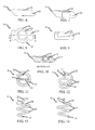
- the surgical fastener 2 may include a coil body 4 and a separately manufactured head 6 that is attached to a proximal end of the coil body 8.
- the distal end of the coil body 10 may be configured for penetrating an implantable prosthesis, tissue, muscle, and/or bone.
- the distal end 10 may include a sharp distal tip, although the distal end may employ any suitable configuration as should be appreciated by one of skill.
- the coil body 4 includes a plurality of coil windings 12. As illustrated, the coil windings 12 may be arranged in a helical or spiral configuration suitable for driving the fastener into and through prosthetic material, tissue, muscle and/or bone. Thus, the coil body may be cylindrical in shape with a circular cross-section, though other cross-sectional shapes such as triangular, rectangular, or any other appropriate shape also are contemplated.
- the coil body 4 may include any number of coil windings 12 with any desired spacing or pitch between the adjacent coil windings and any diameter, or other appropriate transverse dimension, including outer, inner and pitch diameters, suitable for a particular application as should be appreciated by one of skill. In one embodiment, the coil body 4 may include coil windings 12 having the same transverse dimension.
- one or more of the coil windings may have different transverse dimensions relative to each other.
- the coil body may employ coil windings 12 that decrease in transverse dimension from the proximal end toward the distal end to form a coil body 4 with a conical or tapered shape as illustrated in FIGS. 1 and 2 .
- the head may have any suitable configuration desired for a particular application.
- the head includes, but is not limited to, a generally flat distal face from which extends the coil body.
- the opposite or proximal face of the head may have one or more generally flat, round, angled or beveled surfaces, or combinations thereof, as should be apparent to one of skill.
- the head can include at least two radial wings 14 extending in an outward radial direction from the head body 16.
- Each wing 14 may include one or more external threads to engage with a corresponding internal thread of a delivery device.
- the wings 14 may extend radially outwards by an appropriate distance such that they have a maximum outer transverse dimension that is larger than a maximum outer transverse dimension of the coil body. In such an arrangement, the coil windings may not interact with the internal thread of the delivery device when the external threads of the wings 14 engage the internal thread.
- the wings may employ any suitable configuration that should be apparent to one of skill in the art.
- the head 6 may include one or more drive features that may be engaged by a drive member of a delivery device to rotate the head, and thereby rotate the fastener including the coil body 4.
- each wing 14 may be spaced from an adjacent wing 14 by an opening 18, such as a slot, therebetween that is adapted to receive a drive member for driving the surgical fastener, see FIG. 8 .
- the coil body 4 may have a transverse dimension that is smaller than the head body 16 so that the coils do not interfere with the drive member received within the slots. It is to be appreciated that the head 6 may include any number of drive features having any suitable configuration as should be apparent to one of skill.
- the coil body 4 may be attached to the center of the head 6.
- This arrangement may permit maximum use of the entire length of the coil body 4 by permitting over-compression or over-driving of the surgical fastener head 6 into an underlying prosthetic material and/or tissue while reducing, if not eliminating, the potential for ripping or tearing of the material and/or tissue as compared to a fastener in which the coil body terminates closer to the outer periphery of the head 6.
- this may be due to the reduced moment arm, and thus reduced torque, present at the center of the head as it is rotated.
- the coil body 4 it is not required for the coil body 4 to be attached directly at the center of the head 6 in each embodiment of the surgical fastener and that other attachment configurations may be used as should be apparent to one of skill.
- the coil body 4 might be attached to the head 6 at any desirable point between the center of the head and the outer perimeter of the head.
- the proximal end of the coil body 8 may be attached to the head 6 with a proximal-most coil winding 20 being spaced from the head to form a gap therebetween.
- This arrangement may be implemented in place of or together with the center attachment described above.
- the fastener may employ a gap of approximately 0.002 inches to approximately 0.005 inches (0.05 mm to 0.13 mm), although a gap of any suitable size may be employed as should be apparent to one of skill.
- a gap between the coil body 4 and the head 6 is not required for each embodiment of the surgical fastener.
- the head may be attached to the coil body by molding, or otherwise attaching, a non-winding feature of the coil body 8 and head 6 together.
- the head may be molded to a prefabricated coil body using an insert molding or over-molding process as should be apparent to one of skill.
- the coil body 4 may include a non-winding feature such as a central post 22 at the proximal end 8 that is attached to the head, such as by molding.
- a corresponding cavity 24 is formed in the head 6 during molding to accommodate and retain the central post 22 is illustrated in FIG. 10 .
- the central post 22 may include an axial portion and a radial portion that extends from a proximal end of the axial portion.
- the radial portion may be oriented so as to extend in a direction toward one of the wings to maximize its length for enhanced holding between the head and the coil body, though other directions are also possible.
- employing a longer radial portion may increase the amount of torque that may be applied to the coil body through the head due to the increased area the torque is applied to and the increased attachment strength. While a particular non-winding feature for attaching the coil body to the head is describe above, any suitable arrangement may be employed to attach the coil body to the head as should be apparent to one of skill.
- the surgical fastener may be configured to reduce, if not prevent, post-operative back out of the fastener.
- the head 6 may include one or more features 26 that permit tissue ingrowth into or through the head to help anchor the head in position.
- the head 6 may include features 26 for tissue ingrowth such as one or more openings, holes, recesses, cavities, slots and the like that are configured to permit ingrowth into and/or through the head 6 as should be apparent to one of skill in the art.
- tissue ingrowth such as one or more openings, holes, recesses, cavities, slots and the like that are configured to permit ingrowth into and/or through the head 6 as should be apparent to one of skill in the art.
- ingrowth features are not required for each embodiment of the surgical fastener.
- features 26 may be used as driving features that engage with suitably shaped and arranged guide rods to drive the surgical fastener.
- the surgical fasteners may not include the wings and associated slots described above, and instead may include a circular threaded head that engages a corresponding internal thread of a delivery device.
- the surgical fastener may include a coil body having a length of approximately 3 mm (0.118 inches) to approximately 5.5 mm (0.217 inches) extending from the distal face of the head.
- the coil body may include approximately 2.5 turns to approximately 6 turns of coils having a maximum outer transverse dimension of approximately 2.5 mm (0.100 inches) to approximately 4.9 mm (0.193 inches), for delivery through a 5 mm cannula, with a pitch of approximately 0.7 mm (0.03 inches) to approximately 1.1 mm (0.045 inches).
- the head may include wings with an external thread that corresponds to the internal thread of a delivery device.
- the head body may have a maximum outer transverse dimension of approximately 4 mm (0.157 inches) to approximately 4.9 mm (0.193inches) at the slots and a thickness of approximately 0.97 mm (0.030 inches) to approximately 1.02 mm (0.04 inches).
- the head may have a thickness of approximately 0.97 mm (0.030 inches) to approximately 1.02 mm (0.04 inches).
- the radial portion of the center post may have a length of approximately 3.05 mm (0.12 inches) to approximately 3.30 mm (0.13 inches) and may be located about midway between the proximal and distal faces of the head.
- the surgical fastener may employ a coil body and head having any suitable sizes and configurations for a desired application as should be apparent to one of skill in the art.
- the surgical fastener may be made from one or more biocompatible materials that are suitable for a particular surgical application and is sterilized or sterilizable.
- the components of the fastener may be made from a non-absorbable material, an absorbable material or a combination of absorbable and non-absorbable materials.
- the components may be made from, and/or coated with, materials and/or include features that may resist tissue ingrowth and/or adhesions, permit tissue ingrowth and/or adhesions, or a combination thereof.
- the components may be made from metal, plastic and/or any other suitable materials as should be apparent to one of skill in the art.
- the head may be made from a plastic polymer including, but not limited to, polyether ether ketone (PEEK) or acetal, and the coil body may be made from a metal including, but not limited to, stainless steel, nitinol, or titanium. If desired, the head alone or the head and the coil body may be made from an absorbable material metal and/or polymer. Other materials for both the head and coil body are possible.
- PEEK polyether ether ketone
- acetal acetal
- the coil body may be made from a metal including, but not limited to, stainless steel, nitinol, or titanium.
- the head alone or the head and the coil body may be made from an absorbable material metal and/or polymer. Other materials for both the head and coil body are possible.
- the surgical fastener may has an overall length of approximately 4.5 mm (0.177 inches) with a coil length extending from the head of approximately 3.5 mm (0.138 inches).
- the head has a thickness of approximately 1 mm and an outer transverse dimension of approximately 4 mm (0.157 inches) to 4.25 mm (0.167 inches) at the slots.
- the coil body has an outer transverse dimension of approximately 2.7 mm (0.105 inches) and is formed of 0.46 mm (0.018 inch) metal wire to have a constant pitch of approximately 0.91 mm (0.036 inches) to 1.07 mm (0.042 inches).
- the surgical fastener may be delivered to a surgical site using a delivery device that imparts rotation to the fastener and drives the fastener into prosthetic material, tissue, muscle and/or bone.
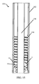
- the delivery device 100 may include an outer tube or cannula 102 for supporting and/or guiding one or more fasteners 2 within the cannula.
- the outer tube 102 may include an internal thread 104 that corresponds to and engages the external thread of the head located on wings 14.
- One or more drive members 106 may extend along the length of the outer tube 102 and mate with the slots 18 of each fastener.
- the drive members 106 may be rotated about the longitudinal axis of the outer tube to rotate the head of the fastener and thereby rotate each fastener 2 within the outer tube 102. Rotation of the head 6 relative to the internal thread 104 of the outer tube 102 in turn provides a reactive thrust to the fastener causing the fastener to be driven in a distal direction along the length of the drive members 106, out of the outer tube 102 and into the prosthetic material, bone, muscle and/or tissue.
- the surgical fastener may be delivered using other suitable arrangements and delivery devices as should be apparent to one of skill in the art.
- the surgical fasteners could be used in delivery devices such as a laparoscopic device, an endoscopic device, a borescopic device, a catheter, a surgical instrument for use in "open" procedures, or any other appropriate surgical instrument.
Landscapes
- Health & Medical Sciences (AREA)
- Life Sciences & Earth Sciences (AREA)
- Surgery (AREA)
- Heart & Thoracic Surgery (AREA)
- Engineering & Computer Science (AREA)
- Biomedical Technology (AREA)
- Nuclear Medicine, Radiotherapy & Molecular Imaging (AREA)
- Medical Informatics (AREA)
- Molecular Biology (AREA)
- Animal Behavior & Ethology (AREA)
- General Health & Medical Sciences (AREA)
- Public Health (AREA)
- Veterinary Medicine (AREA)
- Surgical Instruments (AREA)
Abstract
Description
- Disclosed embodiments are related to a surgical fastener, and more particularly, to a surgical fastener that includes a coil body with an attached head.
- Surgical fasteners are widely used in many different medical procedures. For example, staples, sutures, clips and other fasteners are commonly used in laparoscopic and open surgical procedures.
- In one aspect of the invention, a surgical fastener comprises a head and a coil body that is separate from and attached to the head. The head includes a head body and at least two radial wings extending in an outward radial direction from the head body. Each wing includes at least one external thread to engage with a corresponding internal thread of a delivery device. Each wing is spaced from an adjacent wing by an opening therebetween that is adapted to receive a drive member for driving the surgical fastener. The coil body includes a plurality of coil windings and has a proximal end and a distal end. The proximal end is attached to the head.
- In another aspect of the invention, a surgical fastener comprises a head and a coil body that is separate from and attached to the head. The head includes at least one external thread to engage with a corresponding internal thread of a delivery device. The coil body includes a plurality of coil windings and has a proximal end and a distal end. The proximal end is attached to the center of the head.
- In yet another aspect of the invention, a method includes: rotating a head of a surgical fastener in a distal end of a deployment instrument, wherein the head includes a head body and at least two radial wings extending in an outward radial direction from the head body, each wing including at least one external thread engaged with a corresponding internal thread at the distal end of the deployment instrument, each wing being spaced from an adjacent wing by an opening therebetween, and wherein the surgical fastener includes a coil body that is separate from and attached to the head, the coil body including a plurality of coil windings, the coil body having a proximal end and a distal end, the proximal end being attached to the head; and deploying the surgical fastener out of the deployment instrument.
- Various embodiments of the invention will now be described, by way of example, with reference to the accompanying drawings, in which:
-
FIG. 1 is a schematic front view of a surgical fastener; -
FIG. 2 is a schematic side view of the surgical fastener ofFIG. 1 ; -
FIG. 3 is a schematic top view of the surgical fastener ofFIG. 1 ; -
FIG. 4 is a schematic perspective view of the surgical fastener ofFIG. 1 ; -
FIG. 5 is a schematic perspective view of the surgical fastener ofFIG. 1 ; -
FIG. 6 is a schematic front view of a surgical fastener head; -
FIG. 7 is a schematic perspective view of the surgical fastener head ofFIG. 6 ; -
FIG. 8 is a schematic top view of the surgical fastener head ofFIG. 6 ; -
FIG. 9 is a schematic side view of the surgical fastener head ofFIG. 6 ; -
FIG. 10 is a schematic cross-sectional view of the surgical fastener head ofFIG. 6 ; -
FIG. 11 is a schematic top view of a surgical fastener coil body; -
FIG. 12 is a schematic perspective view of the surgical fastener coil body ofFIG. 11 ; -
FIG. 13 is a schematic front view of the surgical fastener coil body ofFIG. 11 ; -
FIG. 14 is a schematic side view of the surgical fastener coil body ofFIG. 11 ; and -
FIG. 15 is a schematic cross-sectional view of a delivery device. - It should be understood that aspects of the invention are described herein with reference to the figures, which show illustrative embodiments in accordance with aspects of the invention. The illustrative embodiments described herein are not necessarily intended to show all aspects of the invention, but rather are used to describe a few illustrative embodiments. Thus, aspects of the invention are not intended to be construed narrowly in view of the illustrative embodiments. In addition, it should be understood that aspects of the invention may be used alone or in any suitable combination with other aspects of the invention.
- A surgical fastener is provided for various surgical fastening applications. For example, the surgical fastener may be used to attach an implantable prosthesis, such as a soft tissue repair fabric, to tissue and/or muscle. Other non-limiting applications for the fastener may involve joining portions of tissue and/or muscle together, joining portions of tissue and/or muscle to bone, and/or joining an implantable prosthesis to bone.
- In one embodiment, the surgical fastener may include a coil body and a separate head that is attached to the coil body. This arrangement may improve the manufacturability of the fastener and reduce costs, particularly as compared to costs associated with injection molding a complex surgical fastener. This arrangement may be particularly suited for manufacturing the head and coil body from different materials.
- For the purposes of this application, a transverse dimension of the coil body or head generally refers to a dimension of the coil body or head within a plane that is perpendicular to a long axis of the surgical fastener when it is assembled (e.g. a diameter of a cylindrical coil body, a width of a rectangular head, the length of a side of a triangular coil body, etc...). For example, an outer transverse dimension of the coil body would refer to the lateral distance between opposing outer surfaces of the coil body and an inner transverse dimension of the coil body would refer to the lateral distance between opposing interior surfaces of the coil body. The outer transverse dimensions of the head TH and coil body TC in one embodiment are illustrated in
Fig. 2 and correspond to the width of the head and the diameter of the coil body. It should be noted that in embodiments in which the head and/or the coil body are noncircular, the head and/or coil body may have both minimum and maximum transverse dimensions. - In one embodiment, the head may be configured to be larger, such as wider or greater in diameter, than a transverse dimension of the coil body to engage and secure underlying material and/or tissue. Additionally, the head may include one or more features that cooperate with corresponding features of a delivery device for driving the fastener from the device and into an implantable prosthesis and/or tissue or muscle.
- Depending on the embodiment, the head may include two or more radial wings extending in an outward radial direction from a head body. Each wing may include an external thread to engage with a corresponding internal thread of a delivery device. Each wing may also be spaced from an adjacent wing by an opening, such as a slot, positioned therebetween and adapted to receive a drive member for driving the surgical fastener. The coil body may have a smaller maximum outer transverse dimension than the wings so that the coil windings do not interact with the internal thread of the delivery device when the external threads of the wings engage the internal thread. The coil body may also have a smaller maximum outer transverse dimension than the head body so that the coils do not interfere with the drive member received within the slots. The head may also include one or more openings for supporting tissue ingrowth thereto.
- In some embodiments, the coil body may be attached to the center of the head. In such an embodiment, a proximal-most coil winding of the coil body may be spaced from a distal face of the head to form a gap therebetween. The coil body may also include a central post at the proximal end that is attached to the center of the head. The central post may be shaped to facilitate retention of the head. For example, the central post may have an axial portion and a radial portion that extends from a proximal end of the axial portion to aid in attaching and retaining the central post relative to the head.
- In one illustrative embodiment shown in
FIGS. 1-5 , thesurgical fastener 2 may include acoil body 4 and a separately manufacturedhead 6 that is attached to a proximal end of thecoil body 8. The distal end of thecoil body 10 may be configured for penetrating an implantable prosthesis, tissue, muscle, and/or bone. In one embodiment, thedistal end 10 may include a sharp distal tip, although the distal end may employ any suitable configuration as should be appreciated by one of skill. - The
coil body 4 includes a plurality ofcoil windings 12. As illustrated, thecoil windings 12 may be arranged in a helical or spiral configuration suitable for driving the fastener into and through prosthetic material, tissue, muscle and/or bone. Thus, the coil body may be cylindrical in shape with a circular cross-section, though other cross-sectional shapes such as triangular, rectangular, or any other appropriate shape also are contemplated. Thecoil body 4 may include any number ofcoil windings 12 with any desired spacing or pitch between the adjacent coil windings and any diameter, or other appropriate transverse dimension, including outer, inner and pitch diameters, suitable for a particular application as should be appreciated by one of skill. In one embodiment, thecoil body 4 may includecoil windings 12 having the same transverse dimension. However, if desired, one or more of the coil windings may have different transverse dimensions relative to each other. For example, the coil body may employcoil windings 12 that decrease in transverse dimension from the proximal end toward the distal end to form acoil body 4 with a conical or tapered shape as illustrated inFIGS. 1 and 2 . - It should be understood that the head may have any suitable configuration desired for a particular application. For example, in one embodiment, the head includes, but is not limited to, a generally flat distal face from which extends the coil body. The opposite or proximal face of the head may have one or more generally flat, round, angled or beveled surfaces, or combinations thereof, as should be apparent to one of skill.
- In one illustrative embodiment, and as shown in
FIGS. 1-10 , the head can include at least tworadial wings 14 extending in an outward radial direction from thehead body 16. Eachwing 14 may include one or more external threads to engage with a corresponding internal thread of a delivery device. Thewings 14 may extend radially outwards by an appropriate distance such that they have a maximum outer transverse dimension that is larger than a maximum outer transverse dimension of the coil body. In such an arrangement, the coil windings may not interact with the internal thread of the delivery device when the external threads of thewings 14 engage the internal thread. It is to be appreciated that the wings may employ any suitable configuration that should be apparent to one of skill in the art. - To facilitate rotation of the fastener, the
head 6 may include one or more drive features that may be engaged by a drive member of a delivery device to rotate the head, and thereby rotate the fastener including thecoil body 4. In one embodiment, eachwing 14 may be spaced from anadjacent wing 14 by anopening 18, such as a slot, therebetween that is adapted to receive a drive member for driving the surgical fastener, seeFIG. 8 . Thecoil body 4 may have a transverse dimension that is smaller than thehead body 16 so that the coils do not interfere with the drive member received within the slots. It is to be appreciated that thehead 6 may include any number of drive features having any suitable configuration as should be apparent to one of skill. - Again referring to
FIGS. 1-5 , in one illustrative embodiment, thecoil body 4 may be attached to the center of thehead 6. This arrangement may permit maximum use of the entire length of thecoil body 4 by permitting over-compression or over-driving of thesurgical fastener head 6 into an underlying prosthetic material and/or tissue while reducing, if not eliminating, the potential for ripping or tearing of the material and/or tissue as compared to a fastener in which the coil body terminates closer to the outer periphery of thehead 6. Without wishing to be bound by theory, this may be due to the reduced moment arm, and thus reduced torque, present at the center of the head as it is rotated. However, it is to be appreciated that it is not required for thecoil body 4 to be attached directly at the center of thehead 6 in each embodiment of the surgical fastener and that other attachment configurations may be used as should be apparent to one of skill. For example, thecoil body 4 might be attached to thehead 6 at any desirable point between the center of the head and the outer perimeter of the head. - It may also be desirable to reduce, if not eliminate, the potential for pinching a prosthetic material and/or tissue between the coil body and the head. In one illustrative embodiment as also shown in
FIGS. 1-5 , the proximal end of thecoil body 8 may be attached to thehead 6 with a proximal-most coil winding 20 being spaced from the head to form a gap therebetween. This arrangement may be implemented in place of or together with the center attachment described above. In one embodiment, the fastener may employ a gap of approximately 0.002 inches to approximately 0.005 inches (0.05 mm to 0.13 mm), although a gap of any suitable size may be employed as should be apparent to one of skill. However, it is to be appreciated that a gap between thecoil body 4 and thehead 6 is not required for each embodiment of the surgical fastener. - Depending on the embodiment, the head may be attached to the coil body by molding, or otherwise attaching, a non-winding feature of the
coil body 8 andhead 6 together. For example, the head may be molded to a prefabricated coil body using an insert molding or over-molding process as should be apparent to one of skill. In one illustrative embodiment shown inFIGS. 10-14 , thecoil body 4 may include a non-winding feature such as acentral post 22 at theproximal end 8 that is attached to the head, such as by molding. A correspondingcavity 24 is formed in thehead 6 during molding to accommodate and retain thecentral post 22 is illustrated inFIG. 10 . Thecentral post 22 may include an axial portion and a radial portion that extends from a proximal end of the axial portion. The radial portion may be oriented so as to extend in a direction toward one of the wings to maximize its length for enhanced holding between the head and the coil body, though other directions are also possible. Without wishing to be bound by theory, employing a longer radial portion may increase the amount of torque that may be applied to the coil body through the head due to the increased area the torque is applied to and the increased attachment strength. While a particular non-winding feature for attaching the coil body to the head is describe above, any suitable arrangement may be employed to attach the coil body to the head as should be apparent to one of skill. - The surgical fastener may be configured to reduce, if not prevent, post-operative back out of the fastener. In one illustrative embodiment as best shown in
FIGS. 3 and8 , thehead 6 may include one ormore features 26 that permit tissue ingrowth into or through the head to help anchor the head in position. In one embodiment, thehead 6 may includefeatures 26 for tissue ingrowth such as one or more openings, holes, recesses, cavities, slots and the like that are configured to permit ingrowth into and/or through thehead 6 as should be apparent to one of skill in the art. However, it is to be appreciated that such ingrowth features are not required for each embodiment of the surgical fastener. Additionally, in some embodiments features 26 may be used as driving features that engage with suitably shaped and arranged guide rods to drive the surgical fastener. In such an embodiment, the surgical fasteners may not include the wings and associated slots described above, and instead may include a circular threaded head that engages a corresponding internal thread of a delivery device. - In one embodiment, the surgical fastener may include a coil body having a length of approximately 3 mm (0.118 inches) to approximately 5.5 mm (0.217 inches) extending from the distal face of the head. The coil body may include approximately 2.5 turns to approximately 6 turns of coils having a maximum outer transverse dimension of approximately 2.5 mm (0.100 inches) to approximately 4.9 mm (0.193 inches), for delivery through a 5 mm cannula, with a pitch of approximately 0.7 mm (0.03 inches) to approximately 1.1 mm (0.045 inches). The head may include wings with an external thread that corresponds to the internal thread of a delivery device. The head body may have a maximum outer transverse dimension of approximately 4 mm (0.157 inches) to approximately 4.9 mm (0.193inches) at the slots and a thickness of approximately 0.97 mm (0.030 inches) to approximately 1.02 mm (0.04 inches). The head may have a thickness of approximately 0.97 mm (0.030 inches) to approximately 1.02 mm (0.04 inches). The radial portion of the center post may have a length of approximately 3.05 mm (0.12 inches) to approximately 3.30 mm (0.13 inches) and may be located about midway between the proximal and distal faces of the head. Of course, the surgical fastener may employ a coil body and head having any suitable sizes and configurations for a desired application as should be apparent to one of skill in the art.
- The surgical fastener may be made from one or more biocompatible materials that are suitable for a particular surgical application and is sterilized or sterilizable. The components of the fastener may be made from a non-absorbable material, an absorbable material or a combination of absorbable and non-absorbable materials. The components may be made from, and/or coated with, materials and/or include features that may resist tissue ingrowth and/or adhesions, permit tissue ingrowth and/or adhesions, or a combination thereof. The components may be made from metal, plastic and/or any other suitable materials as should be apparent to one of skill in the art.
- In one embodiment, the head may be made from a plastic polymer including, but not limited to, polyether ether ketone (PEEK) or acetal, and the coil body may be made from a metal including, but not limited to, stainless steel, nitinol, or titanium. If desired, the head alone or the head and the coil body may be made from an absorbable material metal and/or polymer. Other materials for both the head and coil body are possible.
- In one exemplary embodiment, the surgical fastener may has an overall length of approximately 4.5 mm (0.177 inches) with a coil length extending from the head of approximately 3.5 mm (0.138 inches). The head has a thickness of approximately 1 mm and an outer transverse dimension of approximately 4 mm (0.157 inches) to 4.25 mm (0.167 inches) at the slots. The coil body has an outer transverse dimension of approximately 2.7 mm (0.105 inches) and is formed of 0.46 mm (0.018 inch) metal wire to have a constant pitch of approximately 0.91 mm (0.036 inches) to 1.07 mm (0.042 inches).
- The surgical fastener may be delivered to a surgical site using a delivery device that imparts rotation to the fastener and drives the fastener into prosthetic material, tissue, muscle and/or bone. As shown in
FIG. 15 , thedelivery device 100 may include an outer tube orcannula 102 for supporting and/or guiding one ormore fasteners 2 within the cannula. Theouter tube 102 may include aninternal thread 104 that corresponds to and engages the external thread of the head located onwings 14. One ormore drive members 106 may extend along the length of theouter tube 102 and mate with theslots 18 of each fastener. Thedrive members 106 may be rotated about the longitudinal axis of the outer tube to rotate the head of the fastener and thereby rotate eachfastener 2 within theouter tube 102. Rotation of thehead 6 relative to theinternal thread 104 of theouter tube 102 in turn provides a reactive thrust to the fastener causing the fastener to be driven in a distal direction along the length of thedrive members 106, out of theouter tube 102 and into the prosthetic material, bone, muscle and/or tissue. However, it is to be appreciated that the surgical fastener may be delivered using other suitable arrangements and delivery devices as should be apparent to one of skill in the art. For example, the surgical fasteners could be used in delivery devices such as a laparoscopic device, an endoscopic device, a borescopic device, a catheter, a surgical instrument for use in "open" procedures, or any other appropriate surgical instrument. - It should be understood that the foregoing description of various aspects of at least one embodiment of the invention are intended merely to be illustrative thereof and that other embodiments, modifications, and equivalents of the invention are within the scope of the invention recited in the claims appended hereto. Accordingly, the foregoing description and drawings are by way of example only.
Claims (15)
- A surgical fastener comprising:a head including a head body and at least two radial wings extending in an outward radial direction from the head body, each wing including at least one external thread to engage with a corresponding internal thread of a delivery device, each wing being spaced from an adjacent wing by an opening therebetween that is adapted to receive a drive member for driving the surgical fastener; anda coil body that is separate from and attached to the head, the coil body including a plurality of coil windings, the coil body having a proximal end and a distal end, the proximal end being attached to the head.
- The surgical fastener according to claim 1, wherein a maximum outer transverse dimension of the coil body is smaller than a maximum outer transverse dimension of the wings so that the coil body does not interact with the internal thread of the delivery device when the external threads of the wings engage the internal thread.
- The surgical fastener according to any of claims 1-2, wherein the proximal end of the coil body is attached to a center portion of the head.
- The surgical fastener according to claim 3, wherein the coil body includes a central post at the proximal end that is attached to the center portion of the head.
- The surgical fastener according to any of claims 3-4, wherein the central post includes an axial portion and a radial portion that extends from a proximal end of the axial portion.
- The surgical fastener according to any of claims 1-5, wherein the head body is constructed and arranged to support tissue ingrowth.
- The surgical fastener according to any of claims 1-6, wherein the head body includes one or more openings adapted to receive tissue ingrowth.
- The surgical fastener according to any of claims 1-7, wherein the head and the coil body are fabricated from different materials.
- The surgical fastener according to claim 8, wherein the head comprises a plastic or metal material.
- The surgical fastener according to any of claims 1-9, wherein a maximum outer transverse dimension of the coil body is smaller than a maximum outer transverse dimension of the head so that the coil windings do not interact with the internal thread of the delivery device when the at least one external thread engages the internal thread.
- The surgical fastener according to any of claims 1-10, wherein a proximal-most coil winding of the coil body is spaced from the head to form a gap therebetween.
- The surgical fastener according to claim 11, wherein the gap is between 0.05 mm and 0.13 mm inclusively.
- The surgical fastener according to any of claims 1-12, wherein the coil body extends between 3 mm to 5.5 mm inclusively from a distal face of the head.
- The surgical fastener according to any of claims 1-13, wherein a maximum outer transverse dimension of the coil body is between 2.5 mm to 4.9 mm inclusively.
- The surgical fastener according any of claims 1-14, wherein a maximum outer transverse dimension of the head is between 4 mm to 4.9 mm inclusively.
Applications Claiming Priority (1)
| Application Number | Priority Date | Filing Date | Title |
|---|---|---|---|
| US14/075,464 US9445814B2 (en) | 2013-11-08 | 2013-11-08 | Surgical fastener |
Publications (2)
| Publication Number | Publication Date |
|---|---|
| EP2870924A1 true EP2870924A1 (en) | 2015-05-13 |
| EP2870924B1 EP2870924B1 (en) | 2020-12-30 |
Family
ID=51846575
Family Applications (1)
| Application Number | Title | Priority Date | Filing Date |
|---|---|---|---|
| EP14192145.2A Active EP2870924B1 (en) | 2013-11-08 | 2014-11-06 | Surgical fastener |
Country Status (4)
| Country | Link |
|---|---|
| US (3) | US9445814B2 (en) |
| EP (1) | EP2870924B1 (en) |
| CA (1) | CA2870287C (en) |
| ES (1) | ES2861447T3 (en) |
Cited By (4)
| Publication number | Priority date | Publication date | Assignee | Title |
|---|---|---|---|---|
| EP2939605A1 (en) * | 2014-04-28 | 2015-11-04 | Covidien LP | Surgical fastener having a cap |
| WO2019135028A1 (en) * | 2018-01-05 | 2019-07-11 | Medtentia International Ltd Oy | A medical fastening device |
| US11234701B2 (en) | 2018-09-21 | 2022-02-01 | Covidien Lp | Powered surgical tack applier |
| US11389159B2 (en) | 2018-09-21 | 2022-07-19 | Covidien Lp | Powered surgical tack applier |
Families Citing this family (37)
| Publication number | Priority date | Publication date | Assignee | Title |
|---|---|---|---|---|
| WO2003034925A2 (en) | 2001-10-23 | 2003-05-01 | Tyco Healthcare Group Lp | Surgical fasteners |
| ES2301119T3 (en) | 2002-06-11 | 2008-06-16 | Tyco Healthcare Group Lp | MALE TIGHTS FOR HERNIAS. |
| CA2527778C (en) | 2003-06-13 | 2011-11-08 | Tyco Healthcare Group Lp | Multiple member interconnect for surgical instrument and absorbable screw fastener |
| US8926637B2 (en) | 2003-06-13 | 2015-01-06 | Covidien Lp | Multiple member interconnect for surgical instrument and absorbable screw fastener |
| US10478179B2 (en) | 2004-04-27 | 2019-11-19 | Covidien Lp | Absorbable fastener for hernia mesh fixation |
| US9358010B2 (en) | 2013-03-12 | 2016-06-07 | Covidien Lp | Flex cable and spring-loaded tube for tacking device |
| US9867620B2 (en) | 2013-03-14 | 2018-01-16 | Covidien Lp | Articulation joint for apparatus for endoscopic procedures |
| US9655621B2 (en) | 2013-03-15 | 2017-05-23 | Covidien Lp | Surgical instrument for dispensing tacks and solution |
| US10085746B2 (en) | 2013-06-28 | 2018-10-02 | Covidien Lp | Surgical instrument including rotating end effector and rotation-limiting structure |
| US9358004B2 (en) | 2013-06-28 | 2016-06-07 | Covidien Lp | Articulating apparatus for endoscopic procedures |
| US9668730B2 (en) | 2013-06-28 | 2017-06-06 | Covidien Lp | Articulating apparatus for endoscopic procedures with timing system |
| US9351728B2 (en) | 2013-06-28 | 2016-05-31 | Covidien Lp | Articulating apparatus for endoscopic procedures |
| US20150032130A1 (en) | 2013-07-24 | 2015-01-29 | Covidien Lp | Expanding absorbable tack |
| US9526498B2 (en) | 2013-09-17 | 2016-12-27 | Covidien Lp | Surgical device with a trigger lockout mechanism device |
| US10368870B2 (en) | 2013-11-08 | 2019-08-06 | C.R. Bard, Inc. | Surgical fastener |
| US9615830B2 (en) | 2013-11-08 | 2017-04-11 | C.R. Bard, Inc. | Surgical fastener |
| US9445814B2 (en) | 2013-11-08 | 2016-09-20 | C.R. Bard, Inc. | Surgical fastener |
| US9675353B2 (en) | 2013-11-08 | 2017-06-13 | C.R. Bard, Inc. | Surgical fasteners and associated deployment devices |
| US10335146B2 (en) | 2014-04-02 | 2019-07-02 | Coviden Lp | Surgical fastener applying apparatus, kits and methods for endoscopic procedures |
| US11090097B2 (en) | 2015-03-17 | 2021-08-17 | Covidien Lp | Connecting end effectors to surgical devices |
| US11701096B2 (en) * | 2015-05-28 | 2023-07-18 | National University Of Ireland, Galway | Fistula treatment device |
| US10028733B2 (en) | 2015-05-28 | 2018-07-24 | National University Of Ireland, Galway | Fistula treatment device |
| US10617409B2 (en) | 2016-10-21 | 2020-04-14 | Covidien Lp | Surgical end effectors |
| US11298123B2 (en) | 2016-10-21 | 2022-04-12 | Covidien Lp | Surgical end effectors |
| US10743859B2 (en) | 2016-10-21 | 2020-08-18 | Covidien Lp | Surgical end effectors |
| US10888309B2 (en) | 2017-01-31 | 2021-01-12 | Covidien Lp | Surgical fastener devices with geometric tubes |
| EP3541298B1 (en) | 2017-06-09 | 2021-08-18 | Signum Surgical Limited | An implant for closing an opening in tissue |
| US10675030B2 (en) | 2017-08-04 | 2020-06-09 | C.R. Bard, Inc. | Absorbable surgical coil fastener |
| USD852885S1 (en) * | 2018-01-04 | 2019-07-02 | Height Metal & Springs Solution Limited | Pin |
| US11298126B2 (en) | 2018-05-02 | 2022-04-12 | Covidien Lp | Shipping wedge for end effector installation onto surgical devices |
| US11116500B2 (en) | 2018-06-28 | 2021-09-14 | Covidien Lp | Surgical fastener applying device, kits and methods for endoscopic procedures |
| US11523817B2 (en) | 2019-06-27 | 2022-12-13 | Covidien Lp | Endoluminal pursestring device |
| USD944985S1 (en) | 2019-12-19 | 2022-03-01 | Covidien Lp | Positioning guide cuff |
| US11197675B2 (en) | 2019-12-19 | 2021-12-14 | Covidien Lp | Positioning guide for surgical instruments and surgical instrument systems |
| USD944984S1 (en) | 2019-12-19 | 2022-03-01 | Covidien Lp | Tubular positioning guide |
| CN111481251B (en) * | 2020-05-29 | 2024-09-24 | 科瑞迈吉(苏州)医疗科技有限公司 | Fastening nail and fastening nail implantation device |
| USD1109327S1 (en) | 2024-09-06 | 2026-01-13 | Covidien Lp | Handle for a surgical instrument |
Citations (5)
| Publication number | Priority date | Publication date | Assignee | Title |
|---|---|---|---|---|
| WO2005004727A1 (en) * | 2003-07-11 | 2005-01-20 | Endogun Medical Systems Ltd. | Surgical fasteners and devices for surgical fastening |
| US20070038220A1 (en) * | 2004-04-27 | 2007-02-15 | Shipp John I | Absorbable Fastener for Hernia Mesh Fixation |
| US20100256690A1 (en) * | 2009-04-02 | 2010-10-07 | Andreas Appenzeller | Locking Spiral Anchoring System |
| US20120101526A1 (en) * | 2010-10-26 | 2012-04-26 | Bennett William F | Surgical Suture System |
| WO2012176195A2 (en) * | 2011-06-23 | 2012-12-27 | Valtech Cardio, Ltd. | Closure element for use with annuloplasty structure |
Family Cites Families (45)
| Publication number | Priority date | Publication date | Assignee | Title |
|---|---|---|---|---|
| US2407879A (en) | 1944-07-08 | 1946-09-17 | Aircraft Screw Prod Co | Composite nut |
| US3229374A (en) | 1963-08-20 | 1966-01-18 | Comorau Leo | Thread gauges |
| US4318651A (en) | 1980-04-08 | 1982-03-09 | Ragen Peter D | Fastener for blind holes |
| US4762453A (en) | 1986-01-29 | 1988-08-09 | Textron, Inc. | Helical coil fastener |
| FR2607560A1 (en) | 1986-12-01 | 1988-06-03 | Plombelec | Element for anchoring a support into a material which has low resistance to tearing out |
| GB2217420A (en) | 1988-04-09 | 1989-10-25 | Cryotherm Limited | Screws for joining semi-rigid mats |
| US5256133A (en) | 1990-09-05 | 1993-10-26 | Spitz Robert M | Device for correcting stress urinary incontinence |
| AU1011595A (en) | 1994-01-13 | 1995-07-20 | Ethicon Inc. | Spiral surgical tack |
| US5662683A (en) | 1995-08-22 | 1997-09-02 | Ortho Helix Limited | Open helical organic tissue anchor and method of facilitating healing |
| US7611521B2 (en) | 1996-09-13 | 2009-11-03 | Tendon Technology, Ltd. | Apparatus and methods for tendon or ligament repair |
| US5733307A (en) | 1996-09-17 | 1998-03-31 | Amei Technologies, Inc. | Bone anchor having a suture trough |
| US6248108B1 (en) * | 1998-09-30 | 2001-06-19 | Bionx Implants Oy | Bioabsorbable surgical screw and washer system |
| FR2812188B1 (en) | 2000-07-31 | 2003-06-13 | Spinevision Sa | RACHIS IMMOBILIZATION CAGE AND OSTEOSYNTHESIS, METHOD FOR MANUFACTURING THE CAGE AND DRILLING EQUIPMENT FOR THE LAYOUT OF THE CAGE |
| US6953462B2 (en) | 2000-10-05 | 2005-10-11 | The Cleveland Clinic Foundation | Apparatus for implantation into bone |
| US6488683B2 (en) | 2000-11-08 | 2002-12-03 | Cleveland Clinic Foundation | Method and apparatus for correcting spinal deformity |
| US6551319B2 (en) | 2000-11-08 | 2003-04-22 | The Cleveland Clinic Foundation | Apparatus for implantation into bone |
| US6409445B1 (en) * | 2001-01-24 | 2002-06-25 | James R. Beale | Push pin with rotatable anchor section |
| GB2417208B (en) | 2001-11-28 | 2006-06-28 | Aptus Endosystems Inc | Intraluminal prosthesis attachment systems |
| US8231639B2 (en) | 2001-11-28 | 2012-07-31 | Aptus Endosystems, Inc. | Systems and methods for attaching a prosthesis within a body lumen or hollow organ |
| ES2301119T3 (en) | 2002-06-11 | 2008-06-16 | Tyco Healthcare Group Lp | MALE TIGHTS FOR HERNIAS. |
| CA2527778C (en) * | 2003-06-13 | 2011-11-08 | Tyco Healthcare Group Lp | Multiple member interconnect for surgical instrument and absorbable screw fastener |
| US20050187568A1 (en) | 2004-02-20 | 2005-08-25 | Klenk Alan R. | Devices and methods for closing a patent foramen ovale with a coil-shaped closure device |
| JP4280773B2 (en) | 2004-03-30 | 2009-06-17 | 中央発条工業株式会社 | Locking nut |
| US8114099B2 (en) | 2004-04-27 | 2012-02-14 | Tyco Healthcare Group Lp | Absorbable anchor for hernia mesh fixation |
| US20090118776A1 (en) | 2004-09-24 | 2009-05-07 | Biomec, Inc. | Tissue anchors |
| US7862573B2 (en) | 2006-04-21 | 2011-01-04 | Darois Roger E | Method and apparatus for surgical fastening |
| US20080004626A1 (en) | 2006-05-26 | 2008-01-03 | Glazer Paul A | Orthopedic coil screw insert |
| WO2008021656A2 (en) | 2006-07-21 | 2008-02-21 | Merlot Orthopedix, Inc. | Apparatus and method for body tissue fixation |
| US8087142B2 (en) | 2008-07-02 | 2012-01-03 | Easylap Ltd. | Pivoting tacker |
| US20100010520A1 (en) | 2008-07-11 | 2010-01-14 | Olympus Medical Systems Corp. | Tissue fastener |
| KR20110073452A (en) | 2008-08-15 | 2011-06-29 | 키네틱 스파인 테크놀로지스 인크. | Bone Fixing Screw |
| US20100145393A1 (en) * | 2008-12-05 | 2010-06-10 | Medicinelodge, Inc. | Medical and dental porous implants |
| US20100274266A1 (en) | 2009-04-22 | 2010-10-28 | Ofir Rimer | Rotary tack |
| US8523881B2 (en) | 2010-07-26 | 2013-09-03 | Valtech Cardio, Ltd. | Multiple anchor delivery tool |
| JP5075885B2 (en) * | 2009-07-13 | 2012-11-21 | シャープ株式会社 | Two-component developer, developing device, image forming apparatus and image forming method |
| WO2011092692A2 (en) | 2010-01-26 | 2011-08-04 | Novolap Medical Ltd. | Articulating medical instrument |
| US20110295282A1 (en) | 2010-05-26 | 2011-12-01 | Tyco Healthcare Group Lp | Fastener and drive method for soft tissue repair |
| AU2012211082B2 (en) | 2011-01-28 | 2015-11-05 | Apica Cardiovascular Limited | Systems for sealing a tissue wall puncture |
| US9072511B2 (en) | 2011-03-25 | 2015-07-07 | Kardium Inc. | Medical kit for constricting tissue or a bodily orifice, for example, a mitral valve |
| AU2012313955B2 (en) | 2011-09-26 | 2017-01-12 | Artack Medical (2013) Ltd. | Surgical fastening device and method |
| US9500217B2 (en) | 2012-07-03 | 2016-11-22 | Jörg Schwarzbich | Method for producing threaded parts |
| US9445814B2 (en) | 2013-11-08 | 2016-09-20 | C.R. Bard, Inc. | Surgical fastener |
| US9615830B2 (en) | 2013-11-08 | 2017-04-11 | C.R. Bard, Inc. | Surgical fastener |
| US10368870B2 (en) | 2013-11-08 | 2019-08-06 | C.R. Bard, Inc. | Surgical fastener |
| US9675353B2 (en) | 2013-11-08 | 2017-06-13 | C.R. Bard, Inc. | Surgical fasteners and associated deployment devices |
-
2013
- 2013-11-08 US US14/075,464 patent/US9445814B2/en active Active
-
2014
- 2014-11-06 ES ES14192145T patent/ES2861447T3/en active Active
- 2014-11-06 EP EP14192145.2A patent/EP2870924B1/en active Active
- 2014-11-07 CA CA2870287A patent/CA2870287C/en active Active
-
2016
- 2016-08-25 US US15/246,888 patent/US10363030B2/en active Active
-
2019
- 2019-06-07 US US16/434,598 patent/US11103238B2/en active Active
Patent Citations (5)
| Publication number | Priority date | Publication date | Assignee | Title |
|---|---|---|---|---|
| WO2005004727A1 (en) * | 2003-07-11 | 2005-01-20 | Endogun Medical Systems Ltd. | Surgical fasteners and devices for surgical fastening |
| US20070038220A1 (en) * | 2004-04-27 | 2007-02-15 | Shipp John I | Absorbable Fastener for Hernia Mesh Fixation |
| US20100256690A1 (en) * | 2009-04-02 | 2010-10-07 | Andreas Appenzeller | Locking Spiral Anchoring System |
| US20120101526A1 (en) * | 2010-10-26 | 2012-04-26 | Bennett William F | Surgical Suture System |
| WO2012176195A2 (en) * | 2011-06-23 | 2012-12-27 | Valtech Cardio, Ltd. | Closure element for use with annuloplasty structure |
Cited By (6)
| Publication number | Priority date | Publication date | Assignee | Title |
|---|---|---|---|---|
| EP2939605A1 (en) * | 2014-04-28 | 2015-11-04 | Covidien LP | Surgical fastener having a cap |
| WO2019135028A1 (en) * | 2018-01-05 | 2019-07-11 | Medtentia International Ltd Oy | A medical fastening device |
| US11234701B2 (en) | 2018-09-21 | 2022-02-01 | Covidien Lp | Powered surgical tack applier |
| US11389159B2 (en) | 2018-09-21 | 2022-07-19 | Covidien Lp | Powered surgical tack applier |
| US12295571B2 (en) | 2018-09-21 | 2025-05-13 | Covidien Lp | Powered surgical tack applier |
| US12419640B2 (en) | 2018-09-21 | 2025-09-23 | Covidien Lp | Powered surgical tack applier |
Also Published As
| Publication number | Publication date |
|---|---|
| US20150133972A1 (en) | 2015-05-14 |
| US10363030B2 (en) | 2019-07-30 |
| EP2870924B1 (en) | 2020-12-30 |
| ES2861447T3 (en) | 2021-10-06 |
| CA2870287C (en) | 2019-10-22 |
| CA2870287A1 (en) | 2015-05-08 |
| US9445814B2 (en) | 2016-09-20 |
| US11103238B2 (en) | 2021-08-31 |
| US20170027560A1 (en) | 2017-02-02 |
| US20190282229A1 (en) | 2019-09-19 |
Similar Documents
| Publication | Publication Date | Title |
|---|---|---|
| US11103238B2 (en) | Surgical fastener | |
| US11246594B2 (en) | Surgical fastener | |
| US11627965B2 (en) | Surgical fastener | |
| US8795299B2 (en) | Anchoring screw device | |
| US9936939B2 (en) | Tissue repair devices | |
| US20130211450A1 (en) | Tissue repair implant and delivery device and method | |
| AU2009316233B2 (en) | Suture device | |
| US11517314B2 (en) | Absorbable surgical coil fastener | |
| EP2870928A1 (en) | Surgical fasteners and associated deployment devices | |
| EP2939605A1 (en) | Surgical fastener having a cap | |
| JP2017536942A (en) | Suture anchor with ribbed augmentation |
Legal Events
| Date | Code | Title | Description |
|---|---|---|---|
| PUAI | Public reference made under article 153(3) epc to a published international application that has entered the european phase |
Free format text: ORIGINAL CODE: 0009012 |
|
| 17P | Request for examination filed |
Effective date: 20141106 |
|
| AK | Designated contracting states |
Kind code of ref document: A1 Designated state(s): AL AT BE BG CH CY CZ DE DK EE ES FI FR GB GR HR HU IE IS IT LI LT LU LV MC MK MT NL NO PL PT RO RS SE SI SK SM TR |
|
| AX | Request for extension of the european patent |
Extension state: BA ME |
|
| R17P | Request for examination filed (corrected) |
Effective date: 20151112 |
|
| RBV | Designated contracting states (corrected) |
Designated state(s): AL AT BE BG CH CY CZ DE DK EE ES FI FR GB GR HR HU IE IS IT LI LT LU LV MC MK MT NL NO PL PT RO RS SE SI SK SM TR |
|
| STAA | Information on the status of an ep patent application or granted ep patent |
Free format text: STATUS: EXAMINATION IS IN PROGRESS |
|
| 17Q | First examination report despatched |
Effective date: 20181106 |
|
| GRAP | Despatch of communication of intention to grant a patent |
Free format text: ORIGINAL CODE: EPIDOSNIGR1 |
|
| STAA | Information on the status of an ep patent application or granted ep patent |
Free format text: STATUS: GRANT OF PATENT IS INTENDED |
|
| INTG | Intention to grant announced |
Effective date: 20200715 |
|
| GRAS | Grant fee paid |
Free format text: ORIGINAL CODE: EPIDOSNIGR3 |
|
| GRAA | (expected) grant |
Free format text: ORIGINAL CODE: 0009210 |
|
| STAA | Information on the status of an ep patent application or granted ep patent |
Free format text: STATUS: THE PATENT HAS BEEN GRANTED |
|
| AK | Designated contracting states |
Kind code of ref document: B1 Designated state(s): AL AT BE BG CH CY CZ DE DK EE ES FI FR GB GR HR HU IE IS IT LI LT LU LV MC MK MT NL NO PL PT RO RS SE SI SK SM TR |
|
| REG | Reference to a national code |
Ref country code: GB Ref legal event code: FG4D |
|
| REG | Reference to a national code |
Ref country code: AT Ref legal event code: REF Ref document number: 1349126 Country of ref document: AT Kind code of ref document: T Effective date: 20210115 |
|
| REG | Reference to a national code |
Ref country code: DE Ref legal event code: R096 Ref document number: 602014073758 Country of ref document: DE |
|
| REG | Reference to a national code |
Ref country code: IE Ref legal event code: FG4D |
|
| PG25 | Lapsed in a contracting state [announced via postgrant information from national office to epo] |
Ref country code: NO Free format text: LAPSE BECAUSE OF FAILURE TO SUBMIT A TRANSLATION OF THE DESCRIPTION OR TO PAY THE FEE WITHIN THE PRESCRIBED TIME-LIMIT Effective date: 20210330 Ref country code: FI Free format text: LAPSE BECAUSE OF FAILURE TO SUBMIT A TRANSLATION OF THE DESCRIPTION OR TO PAY THE FEE WITHIN THE PRESCRIBED TIME-LIMIT Effective date: 20201230 Ref country code: RS Free format text: LAPSE BECAUSE OF FAILURE TO SUBMIT A TRANSLATION OF THE DESCRIPTION OR TO PAY THE FEE WITHIN THE PRESCRIBED TIME-LIMIT Effective date: 20201230 Ref country code: GR Free format text: LAPSE BECAUSE OF FAILURE TO SUBMIT A TRANSLATION OF THE DESCRIPTION OR TO PAY THE FEE WITHIN THE PRESCRIBED TIME-LIMIT Effective date: 20210331 |
|
| REG | Reference to a national code |
Ref country code: AT Ref legal event code: MK05 Ref document number: 1349126 Country of ref document: AT Kind code of ref document: T Effective date: 20201230 |
|
| PG25 | Lapsed in a contracting state [announced via postgrant information from national office to epo] |
Ref country code: LV Free format text: LAPSE BECAUSE OF FAILURE TO SUBMIT A TRANSLATION OF THE DESCRIPTION OR TO PAY THE FEE WITHIN THE PRESCRIBED TIME-LIMIT Effective date: 20201230 Ref country code: SE Free format text: LAPSE BECAUSE OF FAILURE TO SUBMIT A TRANSLATION OF THE DESCRIPTION OR TO PAY THE FEE WITHIN THE PRESCRIBED TIME-LIMIT Effective date: 20201230 Ref country code: BG Free format text: LAPSE BECAUSE OF FAILURE TO SUBMIT A TRANSLATION OF THE DESCRIPTION OR TO PAY THE FEE WITHIN THE PRESCRIBED TIME-LIMIT Effective date: 20210330 |
|
| REG | Reference to a national code |
Ref country code: NL Ref legal event code: MP Effective date: 20201230 |
|
| PG25 | Lapsed in a contracting state [announced via postgrant information from national office to epo] |
Ref country code: HR Free format text: LAPSE BECAUSE OF FAILURE TO SUBMIT A TRANSLATION OF THE DESCRIPTION OR TO PAY THE FEE WITHIN THE PRESCRIBED TIME-LIMIT Effective date: 20201230 |
|
| REG | Reference to a national code |
Ref country code: LT Ref legal event code: MG9D |
|
| PG25 | Lapsed in a contracting state [announced via postgrant information from national office to epo] |
Ref country code: PT Free format text: LAPSE BECAUSE OF FAILURE TO SUBMIT A TRANSLATION OF THE DESCRIPTION OR TO PAY THE FEE WITHIN THE PRESCRIBED TIME-LIMIT Effective date: 20210430 Ref country code: RO Free format text: LAPSE BECAUSE OF FAILURE TO SUBMIT A TRANSLATION OF THE DESCRIPTION OR TO PAY THE FEE WITHIN THE PRESCRIBED TIME-LIMIT Effective date: 20201230 Ref country code: SK Free format text: LAPSE BECAUSE OF FAILURE TO SUBMIT A TRANSLATION OF THE DESCRIPTION OR TO PAY THE FEE WITHIN THE PRESCRIBED TIME-LIMIT Effective date: 20201230 Ref country code: LT Free format text: LAPSE BECAUSE OF FAILURE TO SUBMIT A TRANSLATION OF THE DESCRIPTION OR TO PAY THE FEE WITHIN THE PRESCRIBED TIME-LIMIT Effective date: 20201230 Ref country code: CZ Free format text: LAPSE BECAUSE OF FAILURE TO SUBMIT A TRANSLATION OF THE DESCRIPTION OR TO PAY THE FEE WITHIN THE PRESCRIBED TIME-LIMIT Effective date: 20201230 Ref country code: EE Free format text: LAPSE BECAUSE OF FAILURE TO SUBMIT A TRANSLATION OF THE DESCRIPTION OR TO PAY THE FEE WITHIN THE PRESCRIBED TIME-LIMIT Effective date: 20201230 Ref country code: NL Free format text: LAPSE BECAUSE OF FAILURE TO SUBMIT A TRANSLATION OF THE DESCRIPTION OR TO PAY THE FEE WITHIN THE PRESCRIBED TIME-LIMIT Effective date: 20201230 |
|
| PG25 | Lapsed in a contracting state [announced via postgrant information from national office to epo] |
Ref country code: PL Free format text: LAPSE BECAUSE OF FAILURE TO SUBMIT A TRANSLATION OF THE DESCRIPTION OR TO PAY THE FEE WITHIN THE PRESCRIBED TIME-LIMIT Effective date: 20201230 Ref country code: AT Free format text: LAPSE BECAUSE OF FAILURE TO SUBMIT A TRANSLATION OF THE DESCRIPTION OR TO PAY THE FEE WITHIN THE PRESCRIBED TIME-LIMIT Effective date: 20201230 |
|
| PG25 | Lapsed in a contracting state [announced via postgrant information from national office to epo] |
Ref country code: IS Free format text: LAPSE BECAUSE OF FAILURE TO SUBMIT A TRANSLATION OF THE DESCRIPTION OR TO PAY THE FEE WITHIN THE PRESCRIBED TIME-LIMIT Effective date: 20210430 |
|
| REG | Reference to a national code |
Ref country code: DE Ref legal event code: R097 Ref document number: 602014073758 Country of ref document: DE |
|
| REG | Reference to a national code |
Ref country code: ES Ref legal event code: FG2A Ref document number: 2861447 Country of ref document: ES Kind code of ref document: T3 Effective date: 20211006 |
|
| PG25 | Lapsed in a contracting state [announced via postgrant information from national office to epo] |
Ref country code: AL Free format text: LAPSE BECAUSE OF FAILURE TO SUBMIT A TRANSLATION OF THE DESCRIPTION OR TO PAY THE FEE WITHIN THE PRESCRIBED TIME-LIMIT Effective date: 20201230 |
|
| PLBE | No opposition filed within time limit |
Free format text: ORIGINAL CODE: 0009261 |
|
| STAA | Information on the status of an ep patent application or granted ep patent |
Free format text: STATUS: NO OPPOSITION FILED WITHIN TIME LIMIT |
|
| PG25 | Lapsed in a contracting state [announced via postgrant information from national office to epo] |
Ref country code: DK Free format text: LAPSE BECAUSE OF FAILURE TO SUBMIT A TRANSLATION OF THE DESCRIPTION OR TO PAY THE FEE WITHIN THE PRESCRIBED TIME-LIMIT Effective date: 20201230 |
|
| 26N | No opposition filed |
Effective date: 20211001 |
|
| PG25 | Lapsed in a contracting state [announced via postgrant information from national office to epo] |
Ref country code: SI Free format text: LAPSE BECAUSE OF FAILURE TO SUBMIT A TRANSLATION OF THE DESCRIPTION OR TO PAY THE FEE WITHIN THE PRESCRIBED TIME-LIMIT Effective date: 20201230 |
|
| PG25 | Lapsed in a contracting state [announced via postgrant information from national office to epo] |
Ref country code: IS Free format text: LAPSE BECAUSE OF FAILURE TO SUBMIT A TRANSLATION OF THE DESCRIPTION OR TO PAY THE FEE WITHIN THE PRESCRIBED TIME-LIMIT Effective date: 20210430 |
|
| PG25 | Lapsed in a contracting state [announced via postgrant information from national office to epo] |
Ref country code: MC Free format text: LAPSE BECAUSE OF FAILURE TO SUBMIT A TRANSLATION OF THE DESCRIPTION OR TO PAY THE FEE WITHIN THE PRESCRIBED TIME-LIMIT Effective date: 20201230 |
|
| REG | Reference to a national code |
Ref country code: CH Ref legal event code: PL |
|
| PG25 | Lapsed in a contracting state [announced via postgrant information from national office to epo] |
Ref country code: LU Free format text: LAPSE BECAUSE OF NON-PAYMENT OF DUE FEES Effective date: 20211106 Ref country code: BE Free format text: LAPSE BECAUSE OF NON-PAYMENT OF DUE FEES Effective date: 20211130 |
|
| REG | Reference to a national code |
Ref country code: BE Ref legal event code: MM Effective date: 20211130 |
|
| PG25 | Lapsed in a contracting state [announced via postgrant information from national office to epo] |
Ref country code: LI Free format text: LAPSE BECAUSE OF NON-PAYMENT OF DUE FEES Effective date: 20211130 Ref country code: CH Free format text: LAPSE BECAUSE OF NON-PAYMENT OF DUE FEES Effective date: 20211130 |
|
| PG25 | Lapsed in a contracting state [announced via postgrant information from national office to epo] |
Ref country code: IE Free format text: LAPSE BECAUSE OF NON-PAYMENT OF DUE FEES Effective date: 20211106 |
|
| PG25 | Lapsed in a contracting state [announced via postgrant information from national office to epo] |
Ref country code: HU Free format text: LAPSE BECAUSE OF FAILURE TO SUBMIT A TRANSLATION OF THE DESCRIPTION OR TO PAY THE FEE WITHIN THE PRESCRIBED TIME-LIMIT; INVALID AB INITIO Effective date: 20141106 |
|
| PG25 | Lapsed in a contracting state [announced via postgrant information from national office to epo] |
Ref country code: CY Free format text: LAPSE BECAUSE OF FAILURE TO SUBMIT A TRANSLATION OF THE DESCRIPTION OR TO PAY THE FEE WITHIN THE PRESCRIBED TIME-LIMIT Effective date: 20201230 |
|
| PG25 | Lapsed in a contracting state [announced via postgrant information from national office to epo] |
Ref country code: SM Free format text: LAPSE BECAUSE OF FAILURE TO SUBMIT A TRANSLATION OF THE DESCRIPTION OR TO PAY THE FEE WITHIN THE PRESCRIBED TIME-LIMIT Effective date: 20201230 |
|
| PG25 | Lapsed in a contracting state [announced via postgrant information from national office to epo] |
Ref country code: MK Free format text: LAPSE BECAUSE OF FAILURE TO SUBMIT A TRANSLATION OF THE DESCRIPTION OR TO PAY THE FEE WITHIN THE PRESCRIBED TIME-LIMIT Effective date: 20201230 |
|
| PG25 | Lapsed in a contracting state [announced via postgrant information from national office to epo] |
Ref country code: MT Free format text: LAPSE BECAUSE OF FAILURE TO SUBMIT A TRANSLATION OF THE DESCRIPTION OR TO PAY THE FEE WITHIN THE PRESCRIBED TIME-LIMIT Effective date: 20201230 |
|
| PGFP | Annual fee paid to national office [announced via postgrant information from national office to epo] |
Ref country code: IT Payment date: 20241022 Year of fee payment: 11 Ref country code: ES Payment date: 20241202 Year of fee payment: 11 |
|
| PG25 | Lapsed in a contracting state [announced via postgrant information from national office to epo] |
Ref country code: TR Free format text: LAPSE BECAUSE OF FAILURE TO SUBMIT A TRANSLATION OF THE DESCRIPTION OR TO PAY THE FEE WITHIN THE PRESCRIBED TIME-LIMIT Effective date: 20201230 |
|
| PGFP | Annual fee paid to national office [announced via postgrant information from national office to epo] |
Ref country code: DE Payment date: 20251022 Year of fee payment: 12 |
|
| PGFP | Annual fee paid to national office [announced via postgrant information from national office to epo] |
Ref country code: GB Payment date: 20251023 Year of fee payment: 12 |
|
| PGFP | Annual fee paid to national office [announced via postgrant information from national office to epo] |
Ref country code: FR Payment date: 20251022 Year of fee payment: 12 |