EP2870917A1 - Support apparatus of ultrasound probe, handsfree ultrasound probe including the support apparatus, and method of operating the support apparatus - Google Patents
Support apparatus of ultrasound probe, handsfree ultrasound probe including the support apparatus, and method of operating the support apparatus Download PDFInfo
- Publication number
- EP2870917A1 EP2870917A1 EP20140157985 EP14157985A EP2870917A1 EP 2870917 A1 EP2870917 A1 EP 2870917A1 EP 20140157985 EP20140157985 EP 20140157985 EP 14157985 A EP14157985 A EP 14157985A EP 2870917 A1 EP2870917 A1 EP 2870917A1
- Authority
- EP
- European Patent Office
- Prior art keywords
- ultrasound probe
- support apparatus
- handsfree
- user
- control unit
- Prior art date
- Legal status (The legal status is an assumption and is not a legal conclusion. Google has not performed a legal analysis and makes no representation as to the accuracy of the status listed.)
- Granted
Links
Images




Classifications
-
- A—HUMAN NECESSITIES
- A61—MEDICAL OR VETERINARY SCIENCE; HYGIENE
- A61B—DIAGNOSIS; SURGERY; IDENTIFICATION
- A61B8/00—Diagnosis using ultrasonic, sonic or infrasonic waves
- A61B8/42—Details of probe positioning or probe attachment to the patient
- A61B8/4209—Details of probe positioning or probe attachment to the patient by using holders, e.g. positioning frames
-
- G—PHYSICS
- G01—MEASURING; TESTING
- G01N—INVESTIGATING OR ANALYSING MATERIALS BY DETERMINING THEIR CHEMICAL OR PHYSICAL PROPERTIES
- G01N29/00—Investigating or analysing materials by the use of ultrasonic, sonic or infrasonic waves; Visualisation of the interior of objects by transmitting ultrasonic or sonic waves through the object
- G01N29/22—Details, e.g. general constructional or apparatus details
- G01N29/24—Probes
-
- A—HUMAN NECESSITIES
- A61—MEDICAL OR VETERINARY SCIENCE; HYGIENE
- A61B—DIAGNOSIS; SURGERY; IDENTIFICATION
- A61B8/00—Diagnosis using ultrasonic, sonic or infrasonic waves
-
- A—HUMAN NECESSITIES
- A61—MEDICAL OR VETERINARY SCIENCE; HYGIENE
- A61B—DIAGNOSIS; SURGERY; IDENTIFICATION
- A61B8/00—Diagnosis using ultrasonic, sonic or infrasonic waves
- A61B8/42—Details of probe positioning or probe attachment to the patient
- A61B8/4209—Details of probe positioning or probe attachment to the patient by using holders, e.g. positioning frames
- A61B8/4236—Details of probe positioning or probe attachment to the patient by using holders, e.g. positioning frames characterised by adhesive patches
-
- A—HUMAN NECESSITIES
- A61—MEDICAL OR VETERINARY SCIENCE; HYGIENE
- A61B—DIAGNOSIS; SURGERY; IDENTIFICATION
- A61B8/00—Diagnosis using ultrasonic, sonic or infrasonic waves
- A61B8/44—Constructional features of the ultrasonic, sonic or infrasonic diagnostic device
- A61B8/4444—Constructional features of the ultrasonic, sonic or infrasonic diagnostic device related to the probe
-
- A—HUMAN NECESSITIES
- A61—MEDICAL OR VETERINARY SCIENCE; HYGIENE
- A61B—DIAGNOSIS; SURGERY; IDENTIFICATION
- A61B8/00—Diagnosis using ultrasonic, sonic or infrasonic waves
- A61B8/46—Ultrasonic, sonic or infrasonic diagnostic devices with special arrangements for interfacing with the operator or the patient
- A61B8/467—Ultrasonic, sonic or infrasonic diagnostic devices with special arrangements for interfacing with the operator or the patient characterised by special input means
-
- A—HUMAN NECESSITIES
- A61—MEDICAL OR VETERINARY SCIENCE; HYGIENE
- A61B—DIAGNOSIS; SURGERY; IDENTIFICATION
- A61B8/00—Diagnosis using ultrasonic, sonic or infrasonic waves
- A61B8/54—Control of the diagnostic device
-
- A—HUMAN NECESSITIES
- A61—MEDICAL OR VETERINARY SCIENCE; HYGIENE
- A61B—DIAGNOSIS; SURGERY; IDENTIFICATION
- A61B8/00—Diagnosis using ultrasonic, sonic or infrasonic waves
- A61B8/44—Constructional features of the ultrasonic, sonic or infrasonic diagnostic device
- A61B8/4427—Device being portable or laptop-like
Definitions
- One or more embodiments of the present invention relate to a support apparatus of an ultrasound probe, a handsfree ultrasound probe including the support apparatus, and a method of operating the support apparatus.
- An ultrasound apparatus a magnetic resonance imaging (MRI) apparatus, a computed tomography (CT) apparatus, an X-ray apparatus, etc. may be used as medical devices for obtaining a medical image of a body.
- these apparatuses may photograph a part of the body or an overall part of the body.
- the overall part of the body may be photographed at a time or the part of the body may be photographed in several times and then photographed images may be combined into one image to obtain a combined image of the whole part of the body.
- An ultrasound diagnosis apparatus includes an ultrasound probe that transmits and receives ultrasound, a signal processing apparatus that performs signal processing on the received ultrasound, and a display apparatus that displays an ultrasound image.
- the ultrasound probe that a user who is a doctor is holding by his/her hand contacts a target object such as a patient body, transmits ultrasound to the target object, and receives an echo signal of the ultrasound.
- a target object such as a patient body
- transmits ultrasound to the target object and receives an echo signal of the ultrasound.
- One or more embodiments of the present invention include a support apparatus of an ultrasound probe that a user may not hold by his/her hand during a diagnosis, a handsfree ultrasound probe including the support apparatus, and a method of operating the support apparatus.
- One or more embodiments of the present invention include a support apparatus of an ultrasound probe capable of remotely controlling a movement of the ultrasound probe, a handsfree ultrasound probe including the support apparatus, and a method of operating the support apparatus.
- a support apparatus of an ultrasonic probe including: a housing including an accommodation unit capable of accommodating an ultrasound probe and an adhesion unit capable of contacting a target object; and a first control unit for controlling an adhesive force with respect to the target object of the adhesion unit according to whether a user touches at least one of the ultrasound probe and the housing.
- the adhesive force when a user touch is detected may be smaller than that when the user touch is not detected.
- the first control unit may control the adhesive force to be smaller than a first reference value if a user touch is detected, and control the adhesive force to be greater than the first reference value if the user touch is not detected.
- the first control unit may be capable of adjusting an intensity of the adhesive force at steps.
- the first control unit may control the adhesive force by using an amount of air between the adhesion unit and the target object.
- the first control unit may include a vacuum pump that adjusts the amount of air.
- the support apparatus may further include: a second control unit for controlling a movement of the ultrasound probe according to whether the user touches at least one of the ultrasound probe and the housing.
- the second control unit may include an actuator that is capable of moving such that the actuator contacts the ultrasound probe or is spaced apart from the ultrasound probe.
- the actuator may be spaced apart from the ultrasound probe such that the ultrasound probe moves if the user touch is detected, and fix the ultrasound probe if the user touch is not detected.
- the actuator may move the ultrasound probe in correspondence to a user command used to move the ultrasound probe if the user touch is not detected, and the user command is input.
- the actuator may move at a trace of a protocol that is previously stored in correspondence to the user command.
- the user command may be remotely input.
- the first control unit may receive whether the user touches at least one of the ultrasound probe and the housing from a sensor disposed in at least one of the ultrasound probe and the housing.
- the sensor may include at least one of a touch sensor, a temperature sensor, a button sensor, a light sensor, and a pressure sensor.
- the ultrasound probe may be detached from the accommodation unit.
- a handsfree ultrasound probe including: an ultrasound probe for irradiating ultrasound to a target object and receiving an echo signal of the ultrasound; an accommodation unit for accommodating the ultrasound probe; and an adhesion unit for contacting the target object.
- the handsfree ultrasound probe may further include: a first control unit for controlling an adhesive force with respect to the target object of the adhesion unit according to whether a user touches the handsfree ultrasound probe.
- the first control unit may control the adhesive force when a user touch is not detected to be greater smaller than that when the user touch is detected.
- a method of operating a handsfree ultrasound probe including: detecting whether a user touches the handsfree ultrasound probe; and controlling an adhesive force of the handsfree ultrasound probe with respect to a target object to be smaller than a first reference value if it is detected that the user touches the handsfree ultrasound probe.
- the method may further include: controlling the adhesive force of the handsfree ultrasound probe with respect to the target object to be greater than the first reference value if it is not detected that the user touches the handsfree ultrasound probe.
- a term 'target object' may include a person, animal, or a part of a person or animal.
- the target object may include organs such as the liver, the heart, the womb, the brain, the breast, the abdominal region, etc., or a blood vessel.
- a "user” may be a medical expert including a doctor, a nurse, a medical laboratory technologist, a medical image expert, a technician repairing medical equipments, or the like.
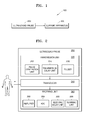
- FIG. 1 is a schematic block diagram of a handsfree ultrasound probe 100 according to an embodiment of the present invention.
- FIG. 2 is a block diagram of an ultrasound probe 200 shown in FIG. 1 .
- FIG. 3 is a block diagram of a support apparatus 300 shown in FIG. 1 .
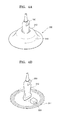
- FIG. 4A illustrates an external appearance of the support apparatus 300 shown in FIG. 1 .
- FIG. 4B illustrates an internal appearance of the support apparatus 300 shown in FIG. 1 .
- the handsfree ultrasound probe 100 includes the ultrasound probe 200 that photographs a target object by using ultrasound to generate an ultrasound image and the support apparatus 300 that supports the ultrasound probe 200 to contact the target object.
- the ultrasound probe 200 transmits ultrasound to the target object and receives an echo signal of the ultrasound from the target object.
- the ultrasound probe 200 may include a transmission unit 220, a transducer 240, and a receiving unit 260 as shown in FIG. 2 .
- the transmission unit 220 provides the transducer 240 with a driving signal.
- the transmission unit 220 may include a pulse generation unit 222, a transmission delay unit 224, and a pulser 226.
- the pulse generation unit 222 generates rate pulses for forming transmission ultrasound according to a predetermined pulse repetition frequency (PRF).
- the transmission delay unit 224 applies delay time to the rate pulses generated by the pulse generation unit 222 to determine a transmission directionality.
- the rate pulses to which the delay time is applied respectively correspond to a plurality of unit devices included in the transducer 240.
- the pulser 226 applies the driving signal (or a driving pulse) to the transducer 240 at timing corresponding to each of the rate pulses to which the delay time is applied.
- the unit devices may be in a one-dimensional array or a two-dimensional array.
- the transducer 240 sends the ultrasound to the target object according to the driving signal provided by the transmission unit 220 and receives the echo signal of the ultrasound reflected from the target object.
- the transducer 240 may include a plurality of unit devices that convert an electrical signal into acoustic energy (or vice versa).
- the unit devices may be in a one-dimensional array or a two-dimensional array.
- the transducer 240 may be implemented as a piezoelectric micromachined ultrasonic (pMUT) that inter-converts the ultrasound and the electrical signal by using a change in pressure while vibrating, a capacitive MUT (cMUT) that inter-converts the ultrasound and the electrical signal by using a change in capacitance, a magnetic MUT (mMUT) that inter-converts the ultrasound and the electrical signal by using a change in a magnetic field, an optical ultrasound detector that inter-converts the ultrasound and the electrical signal by using a change in an optical characteristic, etc.
- pMUT piezoelectric micromachined ultrasonic
- cMUT capacitive MUT
- mMUT magnetic MUT
- optical ultrasound detector that inter-converts the ultrasound and the electrical signal by using a change in an optical characteristic
- the receiving unit 260 may generate ultrasound data by processing signals received from the transducer 240, and include an amplifier 262, an analogue digital converter (ADC) 264, a receiving delay unit 266, and a summing unit 268.
- ADC analogue digital converter
- the amplifier 262 amplifies the signals received from the transducer 240.
- the ADC 264 AD-converts the amplified signals.
- the receiving delay unit 266 applies a delay time used to determine a reception directionality to the digitally converted signals.
- the summing unit 268 generates the ultrasound data by summing signals processed by the receiving delay unit 266. A reflective component may be emphasized from a direction determined by the reception directionality according to the summing performed by the summing unit 268.
- the ultrasound probe 200 necessarily includes the transducer 240, some elements of the transmission unit 220 and the receiving unit 260 may be included in another apparatus.
- the ultrasound probe 200 may not include the summing unit 268 of the receiving unit 260.
- the support apparatus 300 may include a housing 310 that forms an external appearance thereof and a first control unit 320 that controls an adhesive force with respect to a target object of the housing 310 according to whether the user touches at least one of the ultrasound probe 200 and the housing 310.
- the housing 310 may include an accommodation unit 312 that is capable of accommodating the ultrasound probe 200 and an adhesion unit 314 that is capable of being adhered to the target object.
- the ultrasound probe 200 may be detachable from the accommodation unit 312.
- the accommodation unit 312 may be formed as a hole that passes through the housing 310 so that the ultrasound probe 200 may contact the target object but is not limited thereto.
- the accommodation unit 312 may be a groove formed inside the housing 310 or may be a space between a coverer 316 and the adhesion unit 314 of the housing 310.
- the adhesion unit 314 may be a floor surface of the housing 310 to contact the target object.
- the adhesion unit 314 may be disposed to surround the accommodation unit 312.
- the adhesion unit 314 may be the whole floor surface of the housing 310.
- the adhesion unit 314 may be formed of an elastic material. A shape of the adhesion unit 314 may be slightly changed according to an adhesive force with respect to the target object.
- the first control unit 320 controls the adhesive force with respect to the target object of the adhesion unit 314 according to whether the user touches at least one of the ultrasound probe 200 and the housing 310. For example, if it is detected that the user touches at least one of the ultrasound probe 200 and the housing 310, the first control unit 320 controls the adhesive force to be smaller than a first reference value, and, if it is not detected that the user touches at least one of the ultrasound probe 200 and the housing 310, the first control unit 320 controls the adhesive force to be greater than the first reference value. That is, the adhesive force with respect to the target object when a user touch is detected is smaller than that when the user touch is not detected.
- the handsfree ultrasound probe 100 may freely move.
- the handsfree ultrasound probe 100 may contact the target object.
- the first control unit 30 may control an intensity of the adhesive force by using an amount of air between the adhesion unit 314 and the target object.
- the first control unit 320 may include a vacuum pump capable of adjusting the amount of air. That is, the first control unit 320 may control the adhesive force to be stronger by reducing the amount of air between the adhesion unit 314 and the target object and may control the adhesive force to be weaker by increasing the amount of air between the adhesion unit 314 and the target object.
- the first control unit 320 may be disposed inside the housing 310 but is not limited thereto.
- the first control unit 320 may be disposed on the cover 316.
- the first control unit 320 may adjust the intensity of the adhesive force at plural steps. For example, if the user touch is not detected, the first control unit 320 controls the adhesive force to be greater than the first reference value, and, if the user touch is detected, when an angle movement of the ultrasound probe 200 is detected, the first control unit 320 controls the adhesive force to be smaller than the first reference value and to be greater than a second reference value. When the user touch is detected, if a rectilinear movement (for example, a movement in a normal line direction or a tangent line direction with respect to the target object) of the ultrasound probe 200 is detected, the first control unit 320 controls the adhesive force to be smaller than the second reference value.
- the first control unit 320 may include elements in addition to the vacuum pump.
- the first control unit 320 may be a motor that applies a pressure to contact the adhesion unit 314 to the target object or that separates the adhesion unit 314 from the target object.
- the user Since the adhesive force with respect to the target object differs according to whether there is the user touch as described above, the user does not need to place the handsfree ultrasound probe 100 in a specific portion of the target object and hold the handsfree ultrasound probe 100. Thus, a pain in an arm that is like to occur by operating the ultrasound probe 200 may be reduced.
- the user may operate another function of an ultrasound diagnosis apparatus without using his/her hand to fix the ultrasound probe 200, thereby conveniently operating the ultrasound diagnosis apparatus.
- the handsfree ultrasound probe 100 may photograph an image with respect to a specific region of the target object for a predetermined period of time without shaking, and thus the user may accurately diagnose the specific region.
- FIG. 5 is a schematic block diagram of the handsfree ultrasound probe 100 according to another embodiment of the present invention.
- the handsfree ultrasound probe 100 may further include a sensor 330 that detects a user touch with respect to at least one of the ultrasound probe 200 and the housing 310 of the support apparatus 300.
- the sensor 330 may be at least one of a touch sensor, a temperature sensor, a button sensor, a light sensor, and a pressure sensor.
- the sensor 330 may be disposed in the ultrasound probe 200 or in the housing 310 of the support apparatus 300. If the sensor 330 is disposed in the ultrasound probe 200, the sensor 330 may be electrically connected to the first control unit 320 when the ultrasound probe 200 is accommodated in the accommodation unit 312 of the support apparatus 300. Thus, a detection result of the sensor 330 may be applied to the first control unit 320.
- FIG. 6 is a block diagram of the support apparatus 300 of the ultrasound probe 200 according to another embodiment of the present invention.
- FIG. 7 illustrates an internal appearance of the support apparatus 300 shown in FIG. 6 .
- the support apparatus 300 shown in FIG. 6 may further include a second control unit 340 that controls a movement of the ultrasound probe 200 according to whether a user touch is detected.
- the second control unit 340 may include an actuator that is capable of moving such that the actuator may contact the ultrasound probe 200 or may be spaced apart from the ultrasound probe 200.
- the actuator may be spaced apart from the ultrasound probe 200 such that the ultrasound probe 200 may move if the user touch is detected.
- the actuator may contact and fix the ultrasound probe 200 if the user touch is not detected.
- the second control unit 340 may control a movement of the ultrasound probe 200 according to a protocol that is previous stored.
- FIG. 8 is a block diagram of the support apparatus 300 of the ultrasound probe 200 according to another embodiment of the present invention. Compared to the support apparatus 300 shown in FIG. 7 , the support apparatus 300 shown in FIG. 8 may further include a communication unit 350 that is capable of communicating with an external device. The external device may be a portable terminal as an apparatus capable of inputting a user command. If the ultrasound probe 200 is installed in the accommodation unit 312, the first control unit 320 controls an adhesive force of the adhesion unit 314 to be smaller than a first reference value, and the second control unit 340 fixes the ultrasound probe 200.
- the first control unit 320 controls the adhesive force of the adhesion unit 314 to be greater than the first reference value.
- the second control unit 340 may move the ultrasound probe 200 according to the user command.
- the user command may be remotely input. That is, the user command may be input via wireless communication.
- the second control unit 340 may move the ultrasound probe 200 at one or more degrees of freedom.
- the user command is a movement command according to a protocol that is previous stored.
- a movement trace of the ultrasound probe 200 may be previously stored according to a type (liver, abdomen, etc.) of a target object that is to be photographed.
- the second control unit 340 may move the ultrasound probe 200 to a movement trace corresponding to a selected type of the target object.
- the communication unit 350 is disposed in the support apparatus 300 in FIG. 7 but is not limited thereto.
- the communication unit 350 may be disposed in the ultrasound probe 200, and, when the ultrasound probe 200 is accommodated in the accommodation unit 312, may be electrically connected to the second control unit 340.
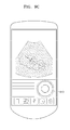
- FIGS. 9A through 9C illustrate examples of a user command used to move the handsfree ultrasound probe 100 according to embodiments of the present invention.
- a user may move the ultrasound probe 200 at one or more degrees of freedom while holding the ultrasound probe 200.
- a user control apparatus for example, a portable terminal, may be used to control a movement of the ultrasound probe 200. Since a gyro sensor, an acceleration sensor, etc, are embedded in the portable terminal, if the user moves the portable terminal at one or more degrees of freedom, a movement of the portable terminal is transmitted to the handsfree ultrasound probe 100, and the ultrasound probe 200 may move in correspondence to the movement of the portable terminal.
- an icon 910 used to control a movement of the ultrasound probe 200 may be disposed in the user control apparatus. The user may control the movement of the ultrasound probe 200 by using the icon 910.
- FIG. 10 illustrates an external appearance of the handsfree ultrasound probe 100 according to another embodiment of the present invention.
- the housing 310 of the support apparatus 300 may be configured as the adhesion unit 314 and the cover 316, and the ultrasound probe 200 may be disposed in an inner space between the adhesion unit 314 and the cover 316.
- the ultrasound probe 200 may further include a wireless communication unit (not shown) that is capable of communicating with an external device (for example, a signal processing apparatus).
- the wireless communication unit may communicate data according to the digital imaging and communication in medicine (DICOM) standard.
- DICOM digital imaging and communication in medicine
- FIG. 11 is a flowchart of a method of operating the handsfree ultrasound probe 100 according to an embodiment of the present invention.
- the sensor 330 detects whether a user touches the handsfree ultrasound probe 100 (operation S1110).
- the sensor 330 may be disposed in the ultrasound probe 200 or in the support apparatus 300.
- the sensor 330 may be a touch sensor that is capable of detecting a user touch but is not limited thereto.
- the sensor 330 may be one of a temperature sensor, a button sensor, a light sensor, and a pressure sensor.
- the first control unit 320 may control an adhesive force of the handsfree ultrasound probe 100 with respect to a target object to be smaller than a first reference value (operation S1120). Thus, the user may separate the handsfree ultrasound probe 100 from the target object.
- the first control unit 320 may control the adhesive force of the handsfree ultrasound probe 100 with respect to the target object to be greater than the first reference value (operation S1130).
- the user may fix the handsfree ultrasound probe 100 to the target object without touching the handsfree ultrasound probe 100 so that the handsfree ultrasound probe 100 may continuously irradiate ultrasound to a specific region of the target object.
- the user may remotely move the ultrasound probe 200 and photograph an ultrasound image while contacting the ultrasound probe 200 to the target object.
- the second control unit 340 may move the ultrasound probe 200 in correspondence to the user command.
- a user may not hold an ultrasound probe during a diagnosis, thereby increasing a user convenience.
- the ultrasound probe moves according to a protocol that is previous stored, thereby more accurately photographing an ultrasound image.
Landscapes
- Health & Medical Sciences (AREA)
- Life Sciences & Earth Sciences (AREA)
- Pathology (AREA)
- General Health & Medical Sciences (AREA)
- Physics & Mathematics (AREA)
- Medical Informatics (AREA)
- Biophysics (AREA)
- Engineering & Computer Science (AREA)
- Biomedical Technology (AREA)
- Heart & Thoracic Surgery (AREA)
- Nuclear Medicine, Radiotherapy & Molecular Imaging (AREA)
- Molecular Biology (AREA)
- Surgery (AREA)
- Animal Behavior & Ethology (AREA)
- Radiology & Medical Imaging (AREA)
- Public Health (AREA)
- Veterinary Medicine (AREA)
- Chemical & Material Sciences (AREA)
- Analytical Chemistry (AREA)
- Biochemistry (AREA)
- General Physics & Mathematics (AREA)
- Immunology (AREA)
- Ultra Sonic Daignosis Equipment (AREA)
Abstract

Description
- This application claims the benefit of Korean Patent Application No.
10-2013-0134355, filed on November 6, 2013 - One or more embodiments of the present invention relate to a support apparatus of an ultrasound probe, a handsfree ultrasound probe including the support apparatus, and a method of operating the support apparatus.
- An ultrasound apparatus, a magnetic resonance imaging (MRI) apparatus, a computed tomography (CT) apparatus, an X-ray apparatus, etc. may be used as medical devices for obtaining a medical image of a body. By reason of a resolution of the medical image or a size of the medical device, these apparatuses may photograph a part of the body or an overall part of the body. The overall part of the body may be photographed at a time or the part of the body may be photographed in several times and then photographed images may be combined into one image to obtain a combined image of the whole part of the body.
- An ultrasound diagnosis apparatus includes an ultrasound probe that transmits and receives ultrasound, a signal processing apparatus that performs signal processing on the received ultrasound, and a display apparatus that displays an ultrasound image.
- The ultrasound probe that a user who is a doctor is holding by his/her hand contacts a target object such as a patient body, transmits ultrasound to the target object, and receives an echo signal of the ultrasound. However, although a user needs to fix the ultrasound probe to the target object when more closely diagnosing a specific part of the target object, it is difficult to fix the ultrasound probe more than a predetermined period of time due to a weight of the ultrasound probe.
- One or more embodiments of the present invention include a support apparatus of an ultrasound probe that a user may not hold by his/her hand during a diagnosis, a handsfree ultrasound probe including the support apparatus, and a method of operating the support apparatus.
- One or more embodiments of the present invention include a support apparatus of an ultrasound probe capable of remotely controlling a movement of the ultrasound probe, a handsfree ultrasound probe including the support apparatus, and a method of operating the support apparatus.
- Additional aspects will be set forth in part in the description which follows and, in part, will be apparent from the description, or may be learned by practice of the presented embodiments.
- According to one or more embodiments of the present invention, a support apparatus of an ultrasonic probe, the support apparatus including: a housing including an accommodation unit capable of accommodating an ultrasound probe and an adhesion unit capable of contacting a target object; and a first control unit for controlling an adhesive force with respect to the target object of the adhesion unit according to whether a user touches at least one of the ultrasound probe and the housing.
- The adhesive force when a user touch is detected may be smaller than that when the user touch is not detected.
- The first control unit may control the adhesive force to be smaller than a first reference value if a user touch is detected, and control the adhesive force to be greater than the first reference value if the user touch is not detected.
- The first control unit may be capable of adjusting an intensity of the adhesive force at steps.
- The first control unit may control the adhesive force by using an amount of air between the adhesion unit and the target object.
- The first control unit may include a vacuum pump that adjusts the amount of air.
- The support apparatus may further include: a second control unit for controlling a movement of the ultrasound probe according to whether the user touches at least one of the ultrasound probe and the housing.
- The second control unit may include an actuator that is capable of moving such that the actuator contacts the ultrasound probe or is spaced apart from the ultrasound probe.
- The actuator may be spaced apart from the ultrasound probe such that the ultrasound probe moves if the user touch is detected, and fix the ultrasound probe if the user touch is not detected.
- The actuator may move the ultrasound probe in correspondence to a user command used to move the ultrasound probe if the user touch is not detected, and the user command is input.
- The actuator may move at a trace of a protocol that is previously stored in correspondence to the user command.
- The user command may be remotely input.
- The first control unit may receive whether the user touches at least one of the ultrasound probe and the housing from a sensor disposed in at least one of the ultrasound probe and the housing.
- The sensor may include at least one of a touch sensor, a temperature sensor, a button sensor, a light sensor, and a pressure sensor.
- The ultrasound probe may be detached from the accommodation unit.
- According to one or more embodiments of the present invention, a handsfree ultrasound probe including: an ultrasound probe for irradiating ultrasound to a target object and receiving an echo signal of the ultrasound; an accommodation unit for accommodating the ultrasound probe; and an adhesion unit for contacting the target object.
- The handsfree ultrasound probe may further include: a first control unit for controlling an adhesive force with respect to the target object of the adhesion unit according to whether a user touches the handsfree ultrasound probe.
- The first control unit may control the adhesive force when a user touch is not detected to be greater smaller than that when the user touch is detected.
- According to one or more embodiments of the present invention, a method of operating a handsfree ultrasound probe, the method including: detecting whether a user touches the handsfree ultrasound probe; and controlling an adhesive force of the handsfree ultrasound probe with respect to a target object to be smaller than a first reference value if it is detected that the user touches the handsfree ultrasound probe.
- The method may further include: controlling the adhesive force of the handsfree ultrasound probe with respect to the target object to be greater than the first reference value if it is not detected that the user touches the handsfree ultrasound probe.
- These and/or other aspects will become apparent and more readily appreciated from the following description of the embodiments, taken in conjunction with the accompanying drawings in which:
-
FIG. 1 is a schematic block diagram of a handsfree ultrasound probe according to an embodiment of the present invention; -
FIG. 2 is a block diagram of an ultrasound probe shown inFIG. 1 ; -
FIG. 3 is a block diagram of a support apparatus shown inFIG. 1 ; -
FIG. 4A illustrates an external appearance of the support apparatus shown inFIG. 1 ; -
FIG. 4B illustrates an internal appearance of the support apparatus shown inFIG. 1 ; -
FIG. 5 is a schematic block diagram of a handsfree ultrasound probe according to another embodiment of the present invention; -
FIG. 6 is a block diagram of a support apparatus of an ultrasound probe according to another embodiment of the present invention; -
FIG. 7 illustrates an internal appearance of the support apparatus shown inFIG. 6 ; -
FIG. 8 is a block diagram of a support apparatus of an ultrasound probe according to another embodiment of the present invention; -
FIGS. 9A through 9C illustrate examples of a user command used to move a handsfree ultrasound probe according to embodiments of the present invention; -
FIG. 10 illustrates an external appearance of a handsfree ultrasound probe according to another embodiment of the present invention; and -
FIG. 11 is a flowchart of a method of operating a handsfree ultrasound probe according to an embodiment of the present invention. - Reference will now be made in detail to embodiments, examples of which are illustrated in the accompanying drawings, wherein like reference numerals refer to the like elements throughout, and redundant explanations are omitted. In this regard, the present embodiments may have different forms and should not be construed as being limited to the descriptions set forth herein. Accordingly, the embodiments are merely described below, by referring to the figures, to explain aspects of the present description. Expressions such as "at least one of," when preceding a list of elements, modify the entire list of elements and do not modify the individual elements of the list.
- Throughout the specification, a term 'target object' may include a person, animal, or a part of a person or animal. For example, the target object may include organs such as the liver, the heart, the womb, the brain, the breast, the abdominal region, etc., or a blood vessel. Throughout the specification, a "user" may be a medical expert including a doctor, a nurse, a medical laboratory technologist, a medical image expert, a technician repairing medical equipments, or the like.
-
FIG. 1 is a schematic block diagram of ahandsfree ultrasound probe 100 according to an embodiment of the present invention.FIG. 2 is a block diagram of anultrasound probe 200 shown inFIG. 1 .FIG. 3 is a block diagram of asupport apparatus 300 shown inFIG. 1 .FIG. 4A illustrates an external appearance of thesupport apparatus 300 shown inFIG. 1 .FIG. 4B illustrates an internal appearance of thesupport apparatus 300 shown inFIG. 1 . - Referring to
FIG. 1 , thehandsfree ultrasound probe 100 includes theultrasound probe 200 that photographs a target objet by using ultrasound to generate an ultrasound image and thesupport apparatus 300 that supports theultrasound probe 200 to contact the target object. - The
ultrasound probe 200 transmits ultrasound to the target object and receives an echo signal of the ultrasound from the target object. Theultrasound probe 200 may include atransmission unit 220, atransducer 240, and a receivingunit 260 as shown inFIG. 2 . - The
transmission unit 220 provides thetransducer 240 with a driving signal. Thetransmission unit 220 may include apulse generation unit 222, atransmission delay unit 224, and apulser 226. - The
pulse generation unit 222 generates rate pulses for forming transmission ultrasound according to a predetermined pulse repetition frequency (PRF). Thetransmission delay unit 224 applies delay time to the rate pulses generated by thepulse generation unit 222 to determine a transmission directionality. The rate pulses to which the delay time is applied respectively correspond to a plurality of unit devices included in thetransducer 240. Thepulser 226 applies the driving signal (or a driving pulse) to thetransducer 240 at timing corresponding to each of the rate pulses to which the delay time is applied. The unit devices may be in a one-dimensional array or a two-dimensional array. - The
transducer 240 sends the ultrasound to the target object according to the driving signal provided by thetransmission unit 220 and receives the echo signal of the ultrasound reflected from the target object. Thetransducer 240 may include a plurality of unit devices that convert an electrical signal into acoustic energy (or vice versa). The unit devices may be in a one-dimensional array or a two-dimensional array. - The
transducer 240 may be implemented as a piezoelectric micromachined ultrasonic (pMUT) that inter-converts the ultrasound and the electrical signal by using a change in pressure while vibrating, a capacitive MUT (cMUT) that inter-converts the ultrasound and the electrical signal by using a change in capacitance, a magnetic MUT (mMUT) that inter-converts the ultrasound and the electrical signal by using a change in a magnetic field, an optical ultrasound detector that inter-converts the ultrasound and the electrical signal by using a change in an optical characteristic, etc. - The receiving
unit 260 may generate ultrasound data by processing signals received from thetransducer 240, and include anamplifier 262, an analogue digital converter (ADC) 264, a receivingdelay unit 266, and a summingunit 268. - The
amplifier 262 amplifies the signals received from thetransducer 240. TheADC 264 AD-converts the amplified signals. The receivingdelay unit 266 applies a delay time used to determine a reception directionality to the digitally converted signals. The summingunit 268 generates the ultrasound data by summing signals processed by the receivingdelay unit 266. A reflective component may be emphasized from a direction determined by the reception directionality according to the summing performed by the summingunit 268. - Although the
ultrasound probe 200 necessarily includes thetransducer 240, some elements of thetransmission unit 220 and the receivingunit 260 may be included in another apparatus. For example, theultrasound probe 200 may not include the summingunit 268 of the receivingunit 260. - The
support apparatus 300 may include ahousing 310 that forms an external appearance thereof and afirst control unit 320 that controls an adhesive force with respect to a target object of thehousing 310 according to whether the user touches at least one of theultrasound probe 200 and thehousing 310. - The
housing 310 may include anaccommodation unit 312 that is capable of accommodating theultrasound probe 200 and anadhesion unit 314 that is capable of being adhered to the target object. Theultrasound probe 200 may be detachable from theaccommodation unit 312. Theaccommodation unit 312 may be formed as a hole that passes through thehousing 310 so that theultrasound probe 200 may contact the target object but is not limited thereto. Theaccommodation unit 312 may be a groove formed inside thehousing 310 or may be a space between acoverer 316 and theadhesion unit 314 of thehousing 310. - The
adhesion unit 314 may be a floor surface of thehousing 310 to contact the target object. When theaccommodation unit 312 is formed as the hole or the groove, theadhesion unit 314 may be disposed to surround theaccommodation unit 312. When theaccommodation unit 312 is a space inside thehousing 310, theadhesion unit 314 may be the whole floor surface of thehousing 310. Theadhesion unit 314 may be formed of an elastic material. A shape of theadhesion unit 314 may be slightly changed according to an adhesive force with respect to the target object. - The
first control unit 320 controls the adhesive force with respect to the target object of theadhesion unit 314 according to whether the user touches at least one of theultrasound probe 200 and thehousing 310. For example, if it is detected that the user touches at least one of theultrasound probe 200 and thehousing 310, thefirst control unit 320 controls the adhesive force to be smaller than a first reference value, and, if it is not detected that the user touches at least one of theultrasound probe 200 and thehousing 310, thefirst control unit 320 controls the adhesive force to be greater than the first reference value. That is, the adhesive force with respect to the target object when a user touch is detected is smaller than that when the user touch is not detected. When the user touches theultrasound probe 200 or thehousing 310, since the adhesive force with respect to the target object is weak, thehandsfree ultrasound probe 100 may freely move. When the user does not touch theultrasound probe 200 or thehousing 310, since the adhesive force with respect to the target object is strong, thehandsfree ultrasound probe 100 may contact the target object. - The first control unit 30 may control an intensity of the adhesive force by using an amount of air between the
adhesion unit 314 and the target object. For example, thefirst control unit 320 may include a vacuum pump capable of adjusting the amount of air. That is, thefirst control unit 320 may control the adhesive force to be stronger by reducing the amount of air between theadhesion unit 314 and the target object and may control the adhesive force to be weaker by increasing the amount of air between theadhesion unit 314 and the target object. Thefirst control unit 320 may be disposed inside thehousing 310 but is not limited thereto. Thefirst control unit 320 may be disposed on thecover 316. - In addition, the
first control unit 320 may adjust the intensity of the adhesive force at plural steps. For example, if the user touch is not detected, thefirst control unit 320 controls the adhesive force to be greater than the first reference value, and, if the user touch is detected, when an angle movement of theultrasound probe 200 is detected, thefirst control unit 320 controls the adhesive force to be smaller than the first reference value and to be greater than a second reference value. When the user touch is detected, if a rectilinear movement (for example, a movement in a normal line direction or a tangent line direction with respect to the target object) of theultrasound probe 200 is detected, thefirst control unit 320 controls the adhesive force to be smaller than the second reference value. Thefirst control unit 320 may include elements in addition to the vacuum pump. For example, thefirst control unit 320 may be a motor that applies a pressure to contact theadhesion unit 314 to the target object or that separates theadhesion unit 314 from the target object. - Since the adhesive force with respect to the target object differs according to whether there is the user touch as described above, the user does not need to place the
handsfree ultrasound probe 100 in a specific portion of the target object and hold thehandsfree ultrasound probe 100. Thus, a pain in an arm that is like to occur by operating theultrasound probe 200 may be reduced. The user may operate another function of an ultrasound diagnosis apparatus without using his/her hand to fix theultrasound probe 200, thereby conveniently operating the ultrasound diagnosis apparatus. Furthermore, thehandsfree ultrasound probe 100 may photograph an image with respect to a specific region of the target object for a predetermined period of time without shaking, and thus the user may accurately diagnose the specific region. -
FIG. 5 is a schematic block diagram of thehandsfree ultrasound probe 100 according to another embodiment of the present invention. Referring toFIG. 5 , thehandsfree ultrasound probe 100 may further include asensor 330 that detects a user touch with respect to at least one of theultrasound probe 200 and thehousing 310 of thesupport apparatus 300. Thesensor 330 may be at least one of a touch sensor, a temperature sensor, a button sensor, a light sensor, and a pressure sensor. Thesensor 330 may be disposed in theultrasound probe 200 or in thehousing 310 of thesupport apparatus 300. If thesensor 330 is disposed in theultrasound probe 200, thesensor 330 may be electrically connected to thefirst control unit 320 when theultrasound probe 200 is accommodated in theaccommodation unit 312 of thesupport apparatus 300. Thus, a detection result of thesensor 330 may be applied to thefirst control unit 320. -
FIG. 6 is a block diagram of thesupport apparatus 300 of theultrasound probe 200 according to another embodiment of the present invention.FIG. 7 illustrates an internal appearance of thesupport apparatus 300 shown inFIG. 6 . Compared to thesupport apparatus 300 shown inFIG. 3 , thesupport apparatus 300 shown inFIG. 6 may further include asecond control unit 340 that controls a movement of theultrasound probe 200 according to whether a user touch is detected. Thesecond control unit 340 may include an actuator that is capable of moving such that the actuator may contact theultrasound probe 200 or may be spaced apart from theultrasound probe 200. The actuator may be spaced apart from theultrasound probe 200 such that theultrasound probe 200 may move if the user touch is detected. The actuator may contact and fix theultrasound probe 200 if the user touch is not detected. - The
second control unit 340 may control a movement of theultrasound probe 200 according to a protocol that is previous stored.FIG. 8 is a block diagram of thesupport apparatus 300 of theultrasound probe 200 according to another embodiment of the present invention. Compared to thesupport apparatus 300 shown inFIG. 7 , thesupport apparatus 300 shown inFIG. 8 may further include acommunication unit 350 that is capable of communicating with an external device. The external device may be a portable terminal as an apparatus capable of inputting a user command. If theultrasound probe 200 is installed in theaccommodation unit 312, thefirst control unit 320 controls an adhesive force of theadhesion unit 314 to be smaller than a first reference value, and thesecond control unit 340 fixes theultrasound probe 200. If a user touch is not detected, thefirst control unit 320 controls the adhesive force of theadhesion unit 314 to be greater than the first reference value. In addition, if the user touch is not detected, and a user command used to move theultrasound probe 200 is input through thecommunication unit 350, thesecond control unit 340 may move theultrasound probe 200 according to the user command. The user command may be remotely input. That is, the user command may be input via wireless communication. Thesecond control unit 340 may move theultrasound probe 200 at one or more degrees of freedom. - Furthermore, if the user command is a movement command according to a protocol that is previous stored. For example, a movement trace of the
ultrasound probe 200 may be previously stored according to a type (liver, abdomen, etc.) of a target object that is to be photographed. If a user command used to select the type of the target object is input, thesecond control unit 340 may move theultrasound probe 200 to a movement trace corresponding to a selected type of the target object. Thecommunication unit 350 is disposed in thesupport apparatus 300 inFIG. 7 but is not limited thereto. Thecommunication unit 350 may be disposed in theultrasound probe 200, and, when theultrasound probe 200 is accommodated in theaccommodation unit 312, may be electrically connected to thesecond control unit 340. -
FIGS. 9A through 9C illustrate examples of a user command used to move thehandsfree ultrasound probe 100 according to embodiments of the present invention. - Referring to
FIG. 9A , after contacting thehandsfree ultrasound probe 100 to a target object, a user may move theultrasound probe 200 at one or more degrees of freedom while holding theultrasound probe 200. - Alternatively, the user ends touching the
handsfree ultrasound probe 100 while contacting thehandsfree ultrasound probe 100 to the target object. Referring toFIG. 9B , a user control apparatus, for example, a portable terminal, may be used to control a movement of theultrasound probe 200. Since a gyro sensor, an acceleration sensor, etc, are embedded in the portable terminal, if the user moves the portable terminal at one or more degrees of freedom, a movement of the portable terminal is transmitted to thehandsfree ultrasound probe 100, and theultrasound probe 200 may move in correspondence to the movement of the portable terminal. - Alternatively, referring to
FIG. 9C , anicon 910 used to control a movement of theultrasound probe 200 may be disposed in the user control apparatus. The user may control the movement of theultrasound probe 200 by using theicon 910. -
FIG. 10 illustrates an external appearance of thehandsfree ultrasound probe 100 according to another embodiment of the present invention. Referring toFIG. 10 , thehousing 310 of thesupport apparatus 300 may be configured as theadhesion unit 314 and thecover 316, and theultrasound probe 200 may be disposed in an inner space between theadhesion unit 314 and thecover 316. Theultrasound probe 200 may further include a wireless communication unit (not shown) that is capable of communicating with an external device (for example, a signal processing apparatus). Thus, the wireless communication unit may communicate data according to the digital imaging and communication in medicine (DICOM) standard. -
FIG. 11 is a flowchart of a method of operating thehandsfree ultrasound probe 100 according to an embodiment of the present invention. Referring toFIG. 11 , thesensor 330 detects whether a user touches the handsfree ultrasound probe 100 (operation S1110). Thesensor 330 may be disposed in theultrasound probe 200 or in thesupport apparatus 300. Thesensor 330 may be a touch sensor that is capable of detecting a user touch but is not limited thereto. Thesensor 330 may be one of a temperature sensor, a button sensor, a light sensor, and a pressure sensor. - If a user touch is detected (operation S1110-Y), the
first control unit 320 may control an adhesive force of thehandsfree ultrasound probe 100 with respect to a target object to be smaller than a first reference value (operation S1120). Thus, the user may separate thehandsfree ultrasound probe 100 from the target object. - If the user touch is not detected (operation S1110-N), the
first control unit 320 may control the adhesive force of thehandsfree ultrasound probe 100 with respect to the target object to be greater than the first reference value (operation S1130). Thus, the user may fix thehandsfree ultrasound probe 100 to the target object without touching thehandsfree ultrasound probe 100 so that thehandsfree ultrasound probe 100 may continuously irradiate ultrasound to a specific region of the target object. Alternatively, the user may remotely move theultrasound probe 200 and photograph an ultrasound image while contacting theultrasound probe 200 to the target object. For example, if the user touch is not detected, and a user command used to move theultrasound probe 200 is input, thesecond control unit 340 may move theultrasound probe 200 in correspondence to the user command. - As described above, according to the one or more of the above embodiments of the present invention, a user may not hold an ultrasound probe during a diagnosis, thereby increasing a user convenience.
- The ultrasound probe moves according to a protocol that is previous stored, thereby more accurately photographing an ultrasound image.
- It should be understood that the exemplary embodiments described therein should be considered in a descriptive sense only and not for purposes of limitation. Descriptions of features or aspects within each embodiment should typically be considered as available for other similar features or aspects in other embodiments.
- While one or more embodiments of the present invention have been described with reference to the figures, it will be understood by those of ordinary skill in the art that various changes in form and details may be made therein without departing from the spirit and scope of the present invention as defined by the following claims.
Claims (15)
- A support apparatus of an ultrasonic probe, the support apparatus comprising:a housing comprising an accommodation unit capable of accommodating an ultrasound probe and an adhesion unit capable of contacting a target object; anda first control unit for controlling an adhesive force with respect to the target object of the adhesion unit according to whether a user touches at least one of the ultrasound probe and the housing.
- The support apparatus of claim 1, wherein the adhesive force when a user touch is detected is smaller than that when the user touch is not detected.
- The support apparatus of claim 1, wherein the first control unit controls the adhesive force to be smaller than a first reference value if a user touch is detected, and controls the adhesive force to be greater than the first reference value if the user touch is not detected.
- The support apparatus of claims 1 or 2, wherein the first control unit is capable of adjusting an intensity of the adhesive force at steps.
- The support apparatus any one of claims 1 to 4, wherein the first control unit controls the adhesive force by using an amount of air between the adhesion unit and the target object.
- The support apparatus of claim 5, wherein the first control unit comprises a vacuum pump that adjusts the amount of air.
- The support apparatus any one of claim 1 to 6, further comprising: a second control unit for controlling a movement of the ultrasound probe according to whether the user touches at least one of the ultrasound probe and the housing.
- The support apparatus of claim 7, wherein the second control unit comprises an actuator that is capable of moving such that the actuator contacts the ultrasound probe or is spaced apart from the ultrasound probe.
- The support apparatus of claim 8, wherein the actuator is spaced apart from the ultrasound probe such that the ultrasound probe moves if the user touch is detected, and fixes the ultrasound probe if the user touch is not detected.
- The support apparatus of claim 8, wherein the actuator moves the ultrasound probe in correspondence to a user command used to move the ultrasound probe if the user touch is not detected, and the user command is input.
- The support apparatus of claim 10, wherein the actuator moves at a trace of a protocol that is previously stored in correspondence to the user command.
- The support apparatus any one of claim 1 to 11, wherein the first control unit receives whether the user touches at least one of the ultrasound probe and the housing from a sensor disposed in at least one of the ultrasound probe and the housing.
- The support apparatus any one of claim 1 to 12, wherein the ultrasound probe is detached from the accommodation unit.
- A method of operating a handsfree ultrasound probe, the method comprising:detecting whether a user touches the handsfree ultrasound probe; andcontrolling an adhesive force of the handsfree ultrasound probe with respect to a target object to be smaller than a first reference value if it is detected that the user touches the handsfree ultrasound probe.
- The method of claim 14, further comprising: controlling the adhesive force of the handsfree ultrasound probe with respect to the target object to be greater than the first reference value if it is not detected that the user touches the handsfree ultrasound probe.
Applications Claiming Priority (1)
| Application Number | Priority Date | Filing Date | Title |
|---|---|---|---|
| KR1020130134355A KR102180465B1 (en) | 2013-11-06 | 2013-11-06 | Supporting device of ultrasound probe, Handfree ultrasound probe comprising the same and Method of operating Handfree ultrasound probe |
Publications (2)
| Publication Number | Publication Date |
|---|---|
| EP2870917A1 true EP2870917A1 (en) | 2015-05-13 |
| EP2870917B1 EP2870917B1 (en) | 2017-06-28 |
Family
ID=50272310
Family Applications (1)
| Application Number | Title | Priority Date | Filing Date |
|---|---|---|---|
| EP14157985.4A Active EP2870917B1 (en) | 2013-11-06 | 2014-03-06 | Support apparatus of ultrasound probe, handsfree ultrasound probe including the support apparatus, and method of operating the support apparatus |
Country Status (4)
| Country | Link |
|---|---|
| US (1) | US10251623B2 (en) |
| EP (1) | EP2870917B1 (en) |
| KR (1) | KR102180465B1 (en) |
| CN (1) | CN104622501B (en) |
Families Citing this family (3)
| Publication number | Priority date | Publication date | Assignee | Title |
|---|---|---|---|---|
| CN109805955A (en) * | 2017-11-22 | 2019-05-28 | 深圳开立生物医疗科技股份有限公司 | A kind of ultrasonic system |
| EP3643242A1 (en) | 2018-10-25 | 2020-04-29 | Koninklijke Philips N.V. | Support unit for a medical imaging element |
| US12324704B2 (en) * | 2020-12-14 | 2025-06-10 | Bard Access Systems, Inc. | Securement of hands-free ultrasound probe |
Citations (5)
| Publication number | Priority date | Publication date | Assignee | Title |
|---|---|---|---|---|
| US20040087851A1 (en) * | 2002-10-31 | 2004-05-06 | Manoa Medical, Inc. A Delaware Corporation | Soft tissue orientation and imaging guide systems and methods |
| JP2006230913A (en) * | 2005-02-28 | 2006-09-07 | Aloka Co Ltd | Sticking device and ultrasonic diagnostic equipment |
| JP2008061894A (en) * | 2006-09-08 | 2008-03-21 | Toshiba Corp | Ultrasonic probe system and ultrasonic diagnostic apparatus |
| US20100174189A1 (en) * | 2007-10-12 | 2010-07-08 | Innoscion, Llc | Remotely controlled implantable transducer and associated displays and controls |
| US20120296216A1 (en) * | 2011-05-16 | 2012-11-22 | Cardiogal Ltd. | Methods and systems of aiming sensor(s) for measuring cardiac parameters |
Family Cites Families (7)
| Publication number | Priority date | Publication date | Assignee | Title |
|---|---|---|---|---|
| JP2664562B2 (en) * | 1991-07-25 | 1997-10-15 | 忠和 鄭 | Ultrasonic probe device |
| JPH05305082A (en) * | 1992-03-17 | 1993-11-19 | Toshiba Corp | Ultrasonic diagnostic and monitoring device |
| US7181854B2 (en) * | 2004-08-17 | 2007-02-27 | Eastway Fair Company Limited | Laser leveling device having a suction mounting arrangement |
| CN201211198Y (en) * | 2008-04-17 | 2009-03-25 | 谈晓明 | Ultrasonic probe with adsorption adjustment device |
| JP2011172736A (en) * | 2010-02-24 | 2011-09-08 | Univ Of Tokyo | Sticking device |
| KR20120095185A (en) * | 2011-02-18 | 2012-08-28 | 삼성메디슨 주식회사 | Ultrasonic probe and ultrasonic diagnosis apparatus with the same |
| CN102824191A (en) * | 2012-09-24 | 2012-12-19 | 四川大学华西医院 | Adhesive Medical In Vitro Ultrasound Probe |
-
2013
- 2013-11-06 KR KR1020130134355A patent/KR102180465B1/en active Active
-
2014
- 2014-03-06 EP EP14157985.4A patent/EP2870917B1/en active Active
- 2014-08-19 CN CN201410407963.3A patent/CN104622501B/en active Active
- 2014-11-06 US US14/535,173 patent/US10251623B2/en active Active
Patent Citations (5)
| Publication number | Priority date | Publication date | Assignee | Title |
|---|---|---|---|---|
| US20040087851A1 (en) * | 2002-10-31 | 2004-05-06 | Manoa Medical, Inc. A Delaware Corporation | Soft tissue orientation and imaging guide systems and methods |
| JP2006230913A (en) * | 2005-02-28 | 2006-09-07 | Aloka Co Ltd | Sticking device and ultrasonic diagnostic equipment |
| JP2008061894A (en) * | 2006-09-08 | 2008-03-21 | Toshiba Corp | Ultrasonic probe system and ultrasonic diagnostic apparatus |
| US20100174189A1 (en) * | 2007-10-12 | 2010-07-08 | Innoscion, Llc | Remotely controlled implantable transducer and associated displays and controls |
| US20120296216A1 (en) * | 2011-05-16 | 2012-11-22 | Cardiogal Ltd. | Methods and systems of aiming sensor(s) for measuring cardiac parameters |
Also Published As
| Publication number | Publication date |
|---|---|
| CN104622501B (en) | 2019-05-28 |
| EP2870917B1 (en) | 2017-06-28 |
| US10251623B2 (en) | 2019-04-09 |
| US20150126871A1 (en) | 2015-05-07 |
| CN104622501A (en) | 2015-05-20 |
| KR20150052661A (en) | 2015-05-14 |
| KR102180465B1 (en) | 2020-11-18 |
Similar Documents
| Publication | Publication Date | Title |
|---|---|---|
| EP2977012B1 (en) | Ultrasound imaging apparatus and controlling method thereof | |
| KR102408440B1 (en) | Method and ultrasound apparatus for setting a preset | |
| KR102642000B1 (en) | Medical image apparatus and operating method for the same | |
| KR20150012144A (en) | Acoustic probe, System including the same and Method of operationg thereof | |
| EP3173026B1 (en) | Medical imaging apparatus and method of operating same | |
| KR102721645B1 (en) | Ultrasound diagnostic apparatus and operating method for the same | |
| US10206655B2 (en) | Ultrasonic imaging apparatus and control method thereof | |
| CN111789633A (en) | Ultrasound diagnostic equipment and control method thereof | |
| KR101051601B1 (en) | Impact Pattern Recognition Ultrasonic Apparatus and Method | |
| US10251623B2 (en) | Support apparatus of ultrasound probe, handsfree ultrasound probe including the support apparatus, and method of operating the support apparatus | |
| KR20150041723A (en) | Ultrasonic probe and medical apparatus including the same | |
| US20150065867A1 (en) | Ultrasound diagnostic apparatus and method of operating the same | |
| CN106983521A (en) | Supersonic imaging apparatus | |
| KR101562211B1 (en) | Integrated chair unit for diagnosis of obstetric and gynecologic | |
| US10695033B2 (en) | Ultrasound diagnostic apparatus and method of operating the same | |
| EP2901938B1 (en) | Ultrasonic probe and ultrasonic diagnostic apparatus including the same | |
| US20150223781A1 (en) | Ultrasonic diagnosis apparatus | |
| KR20160057130A (en) | Ultrasound Probe and Control Method for the same | |
| KR20150012142A (en) | The user controlling device, the hardware device, the medical apparatus comprisiging the same and the method of operating the medical apparatus | |
| EP3031397B1 (en) | Ultrasound imaging apparatus | |
| KR20150047416A (en) | Ultrasound apparatus and method for setting tgc thereof | |
| EP3020337B1 (en) | Ultrasound diagnostic apparatus, operating method thereof, and computer-readable recording medium | |
| KR20170038354A (en) | Ultrasound apparatus and operating method for the same | |
| EP4534215A1 (en) | Ultrasound probe, method of manufacturing the same, and structure combinable with main backing layer of the same | |
| KR20170071391A (en) | Ultrasound apparatus, controlling method of thereof and telemedicine system |
Legal Events
| Date | Code | Title | Description |
|---|---|---|---|
| PUAI | Public reference made under article 153(3) epc to a published international application that has entered the european phase |
Free format text: ORIGINAL CODE: 0009012 |
|
| 17P | Request for examination filed |
Effective date: 20140306 |
|
| AK | Designated contracting states |
Kind code of ref document: A1 Designated state(s): AL AT BE BG CH CY CZ DE DK EE ES FI FR GB GR HR HU IE IS IT LI LT LU LV MC MK MT NL NO PL PT RO RS SE SI SK SM TR |
|
| AX | Request for extension of the european patent |
Extension state: BA ME |
|
| R17P | Request for examination filed (corrected) |
Effective date: 20150904 |
|
| RBV | Designated contracting states (corrected) |
Designated state(s): AL AT BE BG CH CY CZ DE DK EE ES FI FR GB GR HR HU IE IS IT LI LT LU LV MC MK MT NL NO PL PT RO RS SE SI SK SM TR |
|
| 17Q | First examination report despatched |
Effective date: 20160520 |
|
| GRAP | Despatch of communication of intention to grant a patent |
Free format text: ORIGINAL CODE: EPIDOSNIGR1 |
|
| INTG | Intention to grant announced |
Effective date: 20170124 |
|
| GRAS | Grant fee paid |
Free format text: ORIGINAL CODE: EPIDOSNIGR3 |
|
| GRAA | (expected) grant |
Free format text: ORIGINAL CODE: 0009210 |
|
| AK | Designated contracting states |
Kind code of ref document: B1 Designated state(s): AL AT BE BG CH CY CZ DE DK EE ES FI FR GB GR HR HU IE IS IT LI LT LU LV MC MK MT NL NO PL PT RO RS SE SI SK SM TR |
|
| REG | Reference to a national code |
Ref country code: GB Ref legal event code: FG4D |
|
| REG | Reference to a national code |
Ref country code: CH Ref legal event code: EP |
|
| REG | Reference to a national code |
Ref country code: AT Ref legal event code: REF Ref document number: 904133 Country of ref document: AT Kind code of ref document: T Effective date: 20170715 |
|
| REG | Reference to a national code |
Ref country code: IE Ref legal event code: FG4D |
|
| REG | Reference to a national code |
Ref country code: DE Ref legal event code: R096 Ref document number: 602014011123 Country of ref document: DE |
|
| REG | Reference to a national code |
Ref country code: NL Ref legal event code: FP |
|
| PG25 | Lapsed in a contracting state [announced via postgrant information from national office to epo] |
Ref country code: NO Free format text: LAPSE BECAUSE OF FAILURE TO SUBMIT A TRANSLATION OF THE DESCRIPTION OR TO PAY THE FEE WITHIN THE PRESCRIBED TIME-LIMIT Effective date: 20170928 Ref country code: FI Free format text: LAPSE BECAUSE OF FAILURE TO SUBMIT A TRANSLATION OF THE DESCRIPTION OR TO PAY THE FEE WITHIN THE PRESCRIBED TIME-LIMIT Effective date: 20170628 Ref country code: HR Free format text: LAPSE BECAUSE OF FAILURE TO SUBMIT A TRANSLATION OF THE DESCRIPTION OR TO PAY THE FEE WITHIN THE PRESCRIBED TIME-LIMIT Effective date: 20170628 Ref country code: LT Free format text: LAPSE BECAUSE OF FAILURE TO SUBMIT A TRANSLATION OF THE DESCRIPTION OR TO PAY THE FEE WITHIN THE PRESCRIBED TIME-LIMIT Effective date: 20170628 Ref country code: GR Free format text: LAPSE BECAUSE OF FAILURE TO SUBMIT A TRANSLATION OF THE DESCRIPTION OR TO PAY THE FEE WITHIN THE PRESCRIBED TIME-LIMIT Effective date: 20170929 |
|
| REG | Reference to a national code |
Ref country code: LT Ref legal event code: MG4D |
|
| REG | Reference to a national code |
Ref country code: AT Ref legal event code: MK05 Ref document number: 904133 Country of ref document: AT Kind code of ref document: T Effective date: 20170628 |
|
| PG25 | Lapsed in a contracting state [announced via postgrant information from national office to epo] |
Ref country code: BG Free format text: LAPSE BECAUSE OF FAILURE TO SUBMIT A TRANSLATION OF THE DESCRIPTION OR TO PAY THE FEE WITHIN THE PRESCRIBED TIME-LIMIT Effective date: 20170928 Ref country code: SE Free format text: LAPSE BECAUSE OF FAILURE TO SUBMIT A TRANSLATION OF THE DESCRIPTION OR TO PAY THE FEE WITHIN THE PRESCRIBED TIME-LIMIT Effective date: 20170628 Ref country code: RS Free format text: LAPSE BECAUSE OF FAILURE TO SUBMIT A TRANSLATION OF THE DESCRIPTION OR TO PAY THE FEE WITHIN THE PRESCRIBED TIME-LIMIT Effective date: 20170628 Ref country code: LV Free format text: LAPSE BECAUSE OF FAILURE TO SUBMIT A TRANSLATION OF THE DESCRIPTION OR TO PAY THE FEE WITHIN THE PRESCRIBED TIME-LIMIT Effective date: 20170628 |
|
| PG25 | Lapsed in a contracting state [announced via postgrant information from national office to epo] |
Ref country code: CZ Free format text: LAPSE BECAUSE OF FAILURE TO SUBMIT A TRANSLATION OF THE DESCRIPTION OR TO PAY THE FEE WITHIN THE PRESCRIBED TIME-LIMIT Effective date: 20170628 Ref country code: RO Free format text: LAPSE BECAUSE OF FAILURE TO SUBMIT A TRANSLATION OF THE DESCRIPTION OR TO PAY THE FEE WITHIN THE PRESCRIBED TIME-LIMIT Effective date: 20170628 Ref country code: AT Free format text: LAPSE BECAUSE OF FAILURE TO SUBMIT A TRANSLATION OF THE DESCRIPTION OR TO PAY THE FEE WITHIN THE PRESCRIBED TIME-LIMIT Effective date: 20170628 Ref country code: SK Free format text: LAPSE BECAUSE OF FAILURE TO SUBMIT A TRANSLATION OF THE DESCRIPTION OR TO PAY THE FEE WITHIN THE PRESCRIBED TIME-LIMIT Effective date: 20170628 Ref country code: EE Free format text: LAPSE BECAUSE OF FAILURE TO SUBMIT A TRANSLATION OF THE DESCRIPTION OR TO PAY THE FEE WITHIN THE PRESCRIBED TIME-LIMIT Effective date: 20170628 |
|
| REG | Reference to a national code |
Ref country code: FR Ref legal event code: PLFP Year of fee payment: 5 |
|
| PG25 | Lapsed in a contracting state [announced via postgrant information from national office to epo] |
Ref country code: ES Free format text: LAPSE BECAUSE OF FAILURE TO SUBMIT A TRANSLATION OF THE DESCRIPTION OR TO PAY THE FEE WITHIN THE PRESCRIBED TIME-LIMIT Effective date: 20170628 Ref country code: PL Free format text: LAPSE BECAUSE OF FAILURE TO SUBMIT A TRANSLATION OF THE DESCRIPTION OR TO PAY THE FEE WITHIN THE PRESCRIBED TIME-LIMIT Effective date: 20170628 Ref country code: IS Free format text: LAPSE BECAUSE OF FAILURE TO SUBMIT A TRANSLATION OF THE DESCRIPTION OR TO PAY THE FEE WITHIN THE PRESCRIBED TIME-LIMIT Effective date: 20171028 Ref country code: SM Free format text: LAPSE BECAUSE OF FAILURE TO SUBMIT A TRANSLATION OF THE DESCRIPTION OR TO PAY THE FEE WITHIN THE PRESCRIBED TIME-LIMIT Effective date: 20170628 |
|
| REG | Reference to a national code |
Ref country code: DE Ref legal event code: R097 Ref document number: 602014011123 Country of ref document: DE |
|
| PG25 | Lapsed in a contracting state [announced via postgrant information from national office to epo] |
Ref country code: DK Free format text: LAPSE BECAUSE OF FAILURE TO SUBMIT A TRANSLATION OF THE DESCRIPTION OR TO PAY THE FEE WITHIN THE PRESCRIBED TIME-LIMIT Effective date: 20170628 |
|
| PLBE | No opposition filed within time limit |
Free format text: ORIGINAL CODE: 0009261 |
|
| STAA | Information on the status of an ep patent application or granted ep patent |
Free format text: STATUS: NO OPPOSITION FILED WITHIN TIME LIMIT |
|
| 26N | No opposition filed |
Effective date: 20180329 |
|
| PG25 | Lapsed in a contracting state [announced via postgrant information from national office to epo] |
Ref country code: SI Free format text: LAPSE BECAUSE OF FAILURE TO SUBMIT A TRANSLATION OF THE DESCRIPTION OR TO PAY THE FEE WITHIN THE PRESCRIBED TIME-LIMIT Effective date: 20170628 |
|
| REG | Reference to a national code |
Ref country code: CH Ref legal event code: PL |
|
| GBPC | Gb: european patent ceased through non-payment of renewal fee |
Effective date: 20180306 |
|
| PG25 | Lapsed in a contracting state [announced via postgrant information from national office to epo] |
Ref country code: MC Free format text: LAPSE BECAUSE OF FAILURE TO SUBMIT A TRANSLATION OF THE DESCRIPTION OR TO PAY THE FEE WITHIN THE PRESCRIBED TIME-LIMIT Effective date: 20170628 |
|
| REG | Reference to a national code |
Ref country code: BE Ref legal event code: MM Effective date: 20180331 |
|
| REG | Reference to a national code |
Ref country code: IE Ref legal event code: MM4A |
|
| PG25 | Lapsed in a contracting state [announced via postgrant information from national office to epo] |
Ref country code: LU Free format text: LAPSE BECAUSE OF NON-PAYMENT OF DUE FEES Effective date: 20180306 |
|
| PG25 | Lapsed in a contracting state [announced via postgrant information from national office to epo] |
Ref country code: IE Free format text: LAPSE BECAUSE OF NON-PAYMENT OF DUE FEES Effective date: 20180306 |
|
| PG25 | Lapsed in a contracting state [announced via postgrant information from national office to epo] |
Ref country code: GB Free format text: LAPSE BECAUSE OF NON-PAYMENT OF DUE FEES Effective date: 20180306 Ref country code: BE Free format text: LAPSE BECAUSE OF NON-PAYMENT OF DUE FEES Effective date: 20180331 Ref country code: LI Free format text: LAPSE BECAUSE OF NON-PAYMENT OF DUE FEES Effective date: 20180331 Ref country code: CH Free format text: LAPSE BECAUSE OF NON-PAYMENT OF DUE FEES Effective date: 20180331 |
|
| PG25 | Lapsed in a contracting state [announced via postgrant information from national office to epo] |
Ref country code: MT Free format text: LAPSE BECAUSE OF NON-PAYMENT OF DUE FEES Effective date: 20180306 |
|
| PG25 | Lapsed in a contracting state [announced via postgrant information from national office to epo] |
Ref country code: TR Free format text: LAPSE BECAUSE OF FAILURE TO SUBMIT A TRANSLATION OF THE DESCRIPTION OR TO PAY THE FEE WITHIN THE PRESCRIBED TIME-LIMIT Effective date: 20170628 |
|
| PGFP | Annual fee paid to national office [announced via postgrant information from national office to epo] |
Ref country code: NL Payment date: 20200206 Year of fee payment: 7 |
|
| PG25 | Lapsed in a contracting state [announced via postgrant information from national office to epo] |
Ref country code: PT Free format text: LAPSE BECAUSE OF FAILURE TO SUBMIT A TRANSLATION OF THE DESCRIPTION OR TO PAY THE FEE WITHIN THE PRESCRIBED TIME-LIMIT Effective date: 20170628 |
|
| PG25 | Lapsed in a contracting state [announced via postgrant information from national office to epo] |
Ref country code: HU Free format text: LAPSE BECAUSE OF FAILURE TO SUBMIT A TRANSLATION OF THE DESCRIPTION OR TO PAY THE FEE WITHIN THE PRESCRIBED TIME-LIMIT; INVALID AB INITIO Effective date: 20140306 Ref country code: MK Free format text: LAPSE BECAUSE OF NON-PAYMENT OF DUE FEES Effective date: 20170628 Ref country code: CY Free format text: LAPSE BECAUSE OF FAILURE TO SUBMIT A TRANSLATION OF THE DESCRIPTION OR TO PAY THE FEE WITHIN THE PRESCRIBED TIME-LIMIT Effective date: 20170628 |
|
| PG25 | Lapsed in a contracting state [announced via postgrant information from national office to epo] |
Ref country code: AL Free format text: LAPSE BECAUSE OF FAILURE TO SUBMIT A TRANSLATION OF THE DESCRIPTION OR TO PAY THE FEE WITHIN THE PRESCRIBED TIME-LIMIT Effective date: 20170628 |
|
| REG | Reference to a national code |
Ref country code: NL Ref legal event code: MM Effective date: 20210401 |
|
| PG25 | Lapsed in a contracting state [announced via postgrant information from national office to epo] |
Ref country code: NL Free format text: LAPSE BECAUSE OF NON-PAYMENT OF DUE FEES Effective date: 20210401 |
|
| PGFP | Annual fee paid to national office [announced via postgrant information from national office to epo] |
Ref country code: IT Payment date: 20250206 Year of fee payment: 12 |
|
| PGFP | Annual fee paid to national office [announced via postgrant information from national office to epo] |
Ref country code: DE Payment date: 20260320 Year of fee payment: 13 |
|
| PGFP | Annual fee paid to national office [announced via postgrant information from national office to epo] |
Ref country code: FR Payment date: 20260324 Year of fee payment: 13 |