EP2869675A1 - Alphanumeric display assembly - Google Patents
Alphanumeric display assembly Download PDFInfo
- Publication number
- EP2869675A1 EP2869675A1 EP20140185016 EP14185016A EP2869675A1 EP 2869675 A1 EP2869675 A1 EP 2869675A1 EP 20140185016 EP20140185016 EP 20140185016 EP 14185016 A EP14185016 A EP 14185016A EP 2869675 A1 EP2869675 A1 EP 2869675A1
- Authority
- EP
- European Patent Office
- Prior art keywords
- light
- pcb
- alphanumeric
- display assembly
- holes
- Prior art date
- Legal status (The legal status is an assumption and is not a legal conclusion. Google has not performed a legal analysis and makes no representation as to the accuracy of the status listed.)
- Withdrawn
Links
- 239000004676 acrylonitrile butadiene styrene Substances 0.000 claims description 10
- 229920000122 acrylonitrile butadiene styrene Polymers 0.000 claims description 8
- XECAHXYUAAWDEL-UHFFFAOYSA-N acrylonitrile butadiene styrene Chemical compound C=CC=C.C=CC#N.C=CC1=CC=CC=C1 XECAHXYUAAWDEL-UHFFFAOYSA-N 0.000 claims description 6
- 238000000034 method Methods 0.000 claims description 6
- RNFJDJUURJAICM-UHFFFAOYSA-N 2,2,4,4,6,6-hexaphenoxy-1,3,5-triaza-2$l^{5},4$l^{5},6$l^{5}-triphosphacyclohexa-1,3,5-triene Chemical compound N=1P(OC=2C=CC=CC=2)(OC=2C=CC=CC=2)=NP(OC=2C=CC=CC=2)(OC=2C=CC=CC=2)=NP=1(OC=1C=CC=CC=1)OC1=CC=CC=C1 RNFJDJUURJAICM-UHFFFAOYSA-N 0.000 claims description 4
- 239000004743 Polypropylene Substances 0.000 claims description 4
- 239000003063 flame retardant Substances 0.000 claims description 4
- 239000004417 polycarbonate Substances 0.000 claims description 4
- 229920000515 polycarbonate Polymers 0.000 claims description 4
- 229920001155 polypropylene Polymers 0.000 claims description 4
- -1 polypropylene Polymers 0.000 claims description 3
- 239000000853 adhesive Substances 0.000 claims description 2
- 230000001070 adhesive effect Effects 0.000 claims description 2
- 239000004800 polyvinyl chloride Substances 0.000 claims description 2
- 229920001169 thermoplastic Polymers 0.000 claims description 2
- 239000004416 thermosoftening plastic Substances 0.000 claims description 2
- ARXHIJMGSIYYRZ-UHFFFAOYSA-N 1,2,4-trichloro-3-(3,4-dichlorophenyl)benzene Chemical compound C1=C(Cl)C(Cl)=CC=C1C1=C(Cl)C=CC(Cl)=C1Cl ARXHIJMGSIYYRZ-UHFFFAOYSA-N 0.000 description 19
- 238000005286 illumination Methods 0.000 description 8
- 239000000463 material Substances 0.000 description 5
- 210000001072 colon Anatomy 0.000 description 3
- 239000003990 capacitor Substances 0.000 description 2
- 229910052751 metal Inorganic materials 0.000 description 2
- 239000002184 metal Substances 0.000 description 2
- 229920000139 polyethylene terephthalate Polymers 0.000 description 2
- 239000005020 polyethylene terephthalate Substances 0.000 description 2
- 238000005406 washing Methods 0.000 description 2
- 239000004793 Polystyrene Substances 0.000 description 1
- BQCADISMDOOEFD-UHFFFAOYSA-N Silver Chemical compound [Ag] BQCADISMDOOEFD-UHFFFAOYSA-N 0.000 description 1
- XAGFODPZIPBFFR-UHFFFAOYSA-N aluminium Chemical compound [Al] XAGFODPZIPBFFR-UHFFFAOYSA-N 0.000 description 1
- 235000013361 beverage Nutrition 0.000 description 1
- 230000000903 blocking effect Effects 0.000 description 1
- 239000011248 coating agent Substances 0.000 description 1
- 238000000576 coating method Methods 0.000 description 1
- 238000001035 drying Methods 0.000 description 1
- 230000000694 effects Effects 0.000 description 1
- 239000008393 encapsulating agent Substances 0.000 description 1
- 238000005538 encapsulation Methods 0.000 description 1
- 238000005516 engineering process Methods 0.000 description 1
- 239000005357 flat glass Substances 0.000 description 1
- 239000011521 glass Substances 0.000 description 1
- 239000004973 liquid crystal related substance Substances 0.000 description 1
- 238000001465 metallisation Methods 0.000 description 1
- 239000000203 mixture Substances 0.000 description 1
- 239000003973 paint Substances 0.000 description 1
- 229920003023 plastic Polymers 0.000 description 1
- 239000004033 plastic Substances 0.000 description 1
- 239000011347 resin Substances 0.000 description 1
- 229920005989 resin Polymers 0.000 description 1
- 229910052709 silver Inorganic materials 0.000 description 1
- 239000004332 silver Substances 0.000 description 1
- 238000005476 soldering Methods 0.000 description 1
- 238000003466 welding Methods 0.000 description 1
Images

Classifications
-
- H—ELECTRICITY
- H05—ELECTRIC TECHNIQUES NOT OTHERWISE PROVIDED FOR
- H05K—PRINTED CIRCUITS; CASINGS OR CONSTRUCTIONAL DETAILS OF ELECTRIC APPARATUS; MANUFACTURE OF ASSEMBLAGES OF ELECTRICAL COMPONENTS
- H05K1/00—Printed circuits
- H05K1/02—Details
- H05K1/0274—Optical details, e.g. printed circuits comprising integral optical means
-
- H—ELECTRICITY
- H05—ELECTRIC TECHNIQUES NOT OTHERWISE PROVIDED FOR
- H05K—PRINTED CIRCUITS; CASINGS OR CONSTRUCTIONAL DETAILS OF ELECTRIC APPARATUS; MANUFACTURE OF ASSEMBLAGES OF ELECTRICAL COMPONENTS
- H05K2201/00—Indexing scheme relating to printed circuits covered by H05K1/00
- H05K2201/09—Shape and layout
- H05K2201/09009—Substrate related
- H05K2201/09063—Holes or slots in insulating substrate not used for electrical connections
-
- H—ELECTRICITY
- H05—ELECTRIC TECHNIQUES NOT OTHERWISE PROVIDED FOR
- H05K—PRINTED CIRCUITS; CASINGS OR CONSTRUCTIONAL DETAILS OF ELECTRIC APPARATUS; MANUFACTURE OF ASSEMBLAGES OF ELECTRICAL COMPONENTS
- H05K2201/00—Indexing scheme relating to printed circuits covered by H05K1/00
- H05K2201/09—Shape and layout
- H05K2201/09009—Substrate related
- H05K2201/09072—Hole or recess under component or special relationship between hole and component
-
- H—ELECTRICITY
- H05—ELECTRIC TECHNIQUES NOT OTHERWISE PROVIDED FOR
- H05K—PRINTED CIRCUITS; CASINGS OR CONSTRUCTIONAL DETAILS OF ELECTRIC APPARATUS; MANUFACTURE OF ASSEMBLAGES OF ELECTRICAL COMPONENTS
- H05K2201/00—Indexing scheme relating to printed circuits covered by H05K1/00
- H05K2201/10—Details of components or other objects attached to or integrated in a printed circuit board
- H05K2201/10007—Types of components
- H05K2201/10106—Light emitting diode [LED]
-
- H—ELECTRICITY
- H05—ELECTRIC TECHNIQUES NOT OTHERWISE PROVIDED FOR
- H05K—PRINTED CIRCUITS; CASINGS OR CONSTRUCTIONAL DETAILS OF ELECTRIC APPARATUS; MANUFACTURE OF ASSEMBLAGES OF ELECTRICAL COMPONENTS
- H05K2201/00—Indexing scheme relating to printed circuits covered by H05K1/00
- H05K2201/10—Details of components or other objects attached to or integrated in a printed circuit board
- H05K2201/10007—Types of components
- H05K2201/10128—Display
Definitions
- This disclosure relates generally to appliances and, more particularly, to alphanumeric displays for appliances.
- An appliance may have a console assembly with the user interface or control panel provided thereon for selecting or setting one or more of the user-selectable features.
- the user interface may be coupled to a controller.
- the console assembly may include illuminated display elements that encode and present information to the user.
- an embodiment of the disclosed technology relates to an alphanumeric display assembly
- a printed circuit board having a front side and a rear side and a plurality of holes extending through the PCB between the front and rear sides, wherein the holes are arranged to form an alphanumeric indicium; a plurality of light emitting diodes (LEDs) mounted to the PCB on the rear side, wherein at least one LED is mounted adjacent to each hole; and a plurality of light reflecting cups mounted to the PCB on the rear side.
- Each light reflecting cup covers the at least one LED and the adjacent hole, and is spaced from the at least one LED and the adjacent hole to reflect light from the LEDs through the holes so the alphanumeric indicium is visible from the front side.
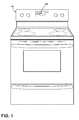
- Figure 1 depicts a front perspective view of an appliance in the form of a range 10 having an example embodiment of an alphanumeric display assembly 100.
- the appliance 10 may be a range, although the alphanumeric display assembly 100 may be included in other types of appliances, non-limiting examples of which may include clothes dryers, laundry drying machines, tumbling or stationary refreshing/revitalizing machines, extractors, non-aqueous washing apparatus, dishwashers, refrigerators, freezers, conventional ovens, microwave ovens, stoves, beverage dispensers, and washing machines.
- the alphanumeric display assembly also may be used in environments other than household appliances and generally applies to any electronic display of alphanumeric indicia, such as clocks, timers, calculators, enumerators, and the like.
- the alphanumeric display assembly 100 is a type of display that includes an array of segments that may be independently illuminated.
- the segments of the display may be illuminated in different combinations.
- the combinations of illuminated segments are selected to produce numerals or letters.
- FIG 2 depicts an exploded perspective view of the front of the alphanumeric display assembly 100 of Figure 1 .
- the alphanumeric display assembly 100 includes a printed circuit board (PCB) 110 and a light reflector 112. With respect to the viewable side of the alphanumeric display assembly 100, the light reflector 112 is placed behind the PCB 110.
- PCB printed circuit board
- the PCB 110 has a front side 114 that includes a plurality of holes 116-128, 132 and 134 extending through the PCB 110.
- the holes 116-128 are arranged to form an alphanumeric indicium (sometime commonly referred to as a 7-segment display, where each hole forms a segment of the alphanumeric indicium).
- the segments formed from the holes 116-128) are of nearly uniform shape and size and are usually formed as elongated hexagons, though trapezoids and rectangles may alternatively be used.
- there may be more than one alphanumeric indicium to complete the display such as three indicia to display three numerals or letters, each alphanumeric indicium being identical to the others as disclosed herein.
- the holes 132, 134 are arranged to form a colon, as for use in a clock display. One or more holes may be disposed to form a decimal, as for use in a calculator. Additional holes in the PCB such as bores 130, 136 may aid in the attachment of the light reflector 112 to the PCB 110.
- the PCB 110 may include multi-layered circuits with electric components such as integrated circuits (ICs), capacitors, resistors, or inductors, mounted on or embedded into the multi-layered circuits. As described below, the PCB may also include one or more illumination devices including light emitting diodes (LEDs), liquid crystal displays (LCDs) or vacuum fluorescent displays (VFDs). Additional elements may be mounted to PCB 110. For example, one or more touch circuits (not shown) may be mounted to the front side 114 of the PCB 110.
- ICs integrated circuits
- LCDs liquid crystal displays
- VFDs vacuum fluorescent displays
- the light reflector 112 may be positioned adjacent to the PCB 110 for directing illumination towards the user. As illustrated, the light reflector 112 may be disposed immediately adjacent to the PCB 110. Preferably, the light reflector 112 is a molded thermoplastic. Other compositions of materials for the light reflector 112 are contemplated and include, but are not limited to: stamped metal, highly reflective aluminized polyethylene terephthalate (PET), molded or formed glass, plate glass, dielectric mirrors, reflective plastic or any other material. Additionally, the material may be coated in whole or in part with one or more reflective materials that may include sputtered aluminum powder, silver coating, silkscreen, metal deposition, reflective paint, etc.
- PET highly reflective aluminized polyethylene terephthalate
- the material may be coated in whole or in part with one or more reflective materials that may include sputtered aluminum powder, silver coating, silkscreen, metal deposition, reflective paint, etc.
- the light reflector 112 may include a first side 113 where a plurality of light cups 140-154 may be disposed on the first side 113 of the light reflector 112.
- the light cups 140-154 may be in the form of an extruded multi-faceted cavity, each positioned to enclose one of the plurality of holes 116-128, 132 and 134 extending through the PCB 110 and a corresponding illumination device described below.
- Each of the plurality of holes 116-128, 132 and 134 and its corresponding illumination device is received in the space defined by one of the three dimensional light cups 140-154 when the light reflector 112 is aligned to the PCB 110.
- the reflecting cups may comprise acrylonitrile butadiene styrene (ABS).
- ABS acrylonitrile butadiene styrene
- PC polycarbonate
- PS polystyrene
- the reflecting cups may include flame retardant acrylonitrile butadiene styrene (FR ABS), Polyvinyl Chloride (PVC), or flame retardant polycarbonate/ acrylonitrile butadiene styrene (FR PC-ABS).
- the light reflector 112 may further include one or more bosses 138, 140 to be used as fasteners.
- the aforementioned bores 130, 136 may receive the bosses 140, 138 respectively and effect a connection to secure the light reflector 112 to the PCB 110.
- the light reflector 112 is mounted to the rear side of the PCB and may be secured by the fastener connection that includes the bosses 140, 138 received in the bores 130, 136.
- Other mounting techniques are contemplated and may include welding, adhesive, soldering onto metal leads that are molded onto the light reflector 112.
- the light reflector 112 may be packaged in a tape-and-reel mechanism and mounted into position by a pick-and-place machine
- Figure 3 depicts an exploded perspective view of the rear of the alphanumeric display assembly 100 of Figure 1 .
- a plurality of LEDs 156-172 are configured such that at least one LED is mounted adjacent to each hole 116-128, 132 and 134.
- Each light reflecting cup covers at least one LED and the adjacent hole. In this way, each light reflecting cup is spaced from at least one LED and its adjacent hole to reflect light from the LEDs through the holes so each alphanumeric indicium is visible from the front side 114 of the PCB 110.
- the illumination devices shown as the LEDs 156-172 may be mounted to the rear side 115 of the PCB 110.
- other electronic components may be mounted to the rear side 115 of the PCB 110 for operating touch circuits or illumination devices.
- one or more components such as capacitors, resistors, connectors, and the like, may be mounted to the rear side 115 of the PCB 110 for operating touch circuits or illumination devices.
- each LED and corresponding hole may be confined within the space formed by the three dimensional wall of the corresponding light cup.
- the light from each LED may be supplied toward a wall of the light cup and then reflected by the wall toward the hole. Some of the reflected light may pass through the hole without being retarded by any light blocking medium. The reflected light may further pass through the thickness of the PCB 110 to reach to the user. It may be understood that the intensity and area of the reflected illumination through the hole may be determined by at least one of the location of the LED relative to the light cup, the geometrical parameters of the light cup, the size and location of the hole and the thickness of the PCB.
- the PCB 110 may include other arrangements of holes along with corresponding LEDs and associated light cups to produce other alphanumeric displays.
- Typical alphanumeric displays include seven-segment displays, nine-segment displays, fourteen-segment display and sixteen segment displays.
- the PCB 110 may include other holes along with corresponding LEDs and associated light cups to produce additional symbols.
- Typical symbols associated with segmented displays include the colon, the comma and the decimal point.
- Multiple alphanumeric displays may be configured to act as a single display units. For example, as shown in the figures, three seven segment displays may form a single display unit.
- the alphanumeric display assembly may achieve a desirably bright output light intensity by direct reflection of the light from an LED off the light cup and through the hole in the PCB.
- the light reflector may be manufactured in a cost efficient manner that far exceeds alternative methods. For example, encapsulation of the LED with a resin to serve as a waveguide to direct the light through the hole may be costly and time-consuming and may result in a less appealing or less bright display over time as the encapsulant ages and discolors.
- the shape and geometrical dimension of light cups or holes may be varied to provide controlled illumination to the user.
- Each light cup may be individually shaped and mounted to the PCB to cover a single hole and adjacent LED. While described in the context of mounting the light reflector to the PCB, the light reflector or any of the light cups may be mounted or integrated into any additional component such that the light reflector is placed in proximity to the PCB and the light cups may reflect light illuminated from the LEDs through the holes in the PCB.
- the light cups may have additional reflective properties added, such as a polished surface, a metallic surface, a colored surface, and/or a surface formed to reflect light a given wavelength.
Landscapes
- Engineering & Computer Science (AREA)
- Microelectronics & Electronic Packaging (AREA)
- Illuminated Signs And Luminous Advertising (AREA)
- Physics & Mathematics (AREA)
- General Physics & Mathematics (AREA)
- Theoretical Computer Science (AREA)
Abstract
Description
- This disclosure relates generally to appliances and, more particularly, to alphanumeric displays for appliances.
- Home appliances are increasingly equipped with a greater number of user-selectable features, typically presented via a user interface. An appliance may have a console assembly with the user interface or control panel provided thereon for selecting or setting one or more of the user-selectable features. The user interface may be coupled to a controller. The console assembly may include illuminated display elements that encode and present information to the user.
- In one aspect, an embodiment of the disclosed technology relates to an alphanumeric display assembly comprising a printed circuit board (PCB), having a front side and a rear side and a plurality of holes extending through the PCB between the front and rear sides, wherein the holes are arranged to form an alphanumeric indicium; a plurality of light emitting diodes (LEDs) mounted to the PCB on the rear side, wherein at least one LED is mounted adjacent to each hole; and a plurality of light reflecting cups mounted to the PCB on the rear side. Each light reflecting cup covers the at least one LED and the adjacent hole, and is spaced from the at least one LED and the adjacent hole to reflect light from the LEDs through the holes so the alphanumeric indicium is visible from the front side.
- In the drawings:
-
Figure 1 depicts a front perspective view of an appliance in the form of a range having an example embodiment of the alphanumeric display assembly. -
Figure 2 depicts an exploded perspective view of the front of the alphanumeric display assembly ofFigure 1 . -
Figure 3 depicts an exploded perspective view of the rear of the alphanumeric display assembly ofFigure 1 . -
Figure 1 depicts a front perspective view of an appliance in the form of arange 10 having an example embodiment of analphanumeric display assembly 100. As illustrated, theappliance 10 may be a range, although thealphanumeric display assembly 100 may be included in other types of appliances, non-limiting examples of which may include clothes dryers, laundry drying machines, tumbling or stationary refreshing/revitalizing machines, extractors, non-aqueous washing apparatus, dishwashers, refrigerators, freezers, conventional ovens, microwave ovens, stoves, beverage dispensers, and washing machines. The alphanumeric display assembly also may be used in environments other than household appliances and generally applies to any electronic display of alphanumeric indicia, such as clocks, timers, calculators, enumerators, and the like. - The
alphanumeric display assembly 100 is a type of display that includes an array of segments that may be independently illuminated. The segments of the display may be illuminated in different combinations. The combinations of illuminated segments are selected to produce numerals or letters. -
Figure 2 depicts an exploded perspective view of the front of thealphanumeric display assembly 100 ofFigure 1 . Thealphanumeric display assembly 100 includes a printed circuit board (PCB) 110 and alight reflector 112. With respect to the viewable side of thealphanumeric display assembly 100, thelight reflector 112 is placed behind thePCB 110. - The PCB 110 has a
front side 114 that includes a plurality of holes 116-128, 132 and 134 extending through thePCB 110. The holes 116-128 are arranged to form an alphanumeric indicium (sometime commonly referred to as a 7-segment display, where each hole forms a segment of the alphanumeric indicium). In most applications, the segments (formed from the holes 116-128) are of nearly uniform shape and size and are usually formed as elongated hexagons, though trapezoids and rectangles may alternatively be used. As shown, there may be more than one alphanumeric indicium to complete the display, such as three indicia to display three numerals or letters, each alphanumeric indicium being identical to the others as disclosed herein. Theholes bores light reflector 112 to thePCB 110. - The PCB 110 may include multi-layered circuits with electric components such as integrated circuits (ICs), capacitors, resistors, or inductors, mounted on or embedded into the multi-layered circuits. As described below, the PCB may also include one or more illumination devices including light emitting diodes (LEDs), liquid crystal displays (LCDs) or vacuum fluorescent displays (VFDs). Additional elements may be mounted to PCB 110. For example, one or more touch circuits (not shown) may be mounted to the
front side 114 of the PCB 110. - The
light reflector 112 may be positioned adjacent to thePCB 110 for directing illumination towards the user. As illustrated, thelight reflector 112 may be disposed immediately adjacent to thePCB 110. Preferably, thelight reflector 112 is a molded thermoplastic. Other compositions of materials for thelight reflector 112 are contemplated and include, but are not limited to: stamped metal, highly reflective aluminized polyethylene terephthalate (PET), molded or formed glass, plate glass, dielectric mirrors, reflective plastic or any other material. Additionally, the material may be coated in whole or in part with one or more reflective materials that may include sputtered aluminum powder, silver coating, silkscreen, metal deposition, reflective paint, etc. - The
light reflector 112 may include afirst side 113 where a plurality of light cups 140-154 may be disposed on thefirst side 113 of thelight reflector 112. The light cups 140-154 may be in the form of an extruded multi-faceted cavity, each positioned to enclose one of the plurality of holes 116-128, 132 and 134 extending through thePCB 110 and a corresponding illumination device described below. Each of the plurality of holes 116-128, 132 and 134 and its corresponding illumination device is received in the space defined by one of the three dimensional light cups 140-154 when thelight reflector 112 is aligned to thePCB 110. - The reflecting cups may comprise acrylonitrile butadiene styrene (ABS). Another material such as polypropylene (PP), polycarbonate (PC), or polystyrene (PS) may be used for the
light reflector 112. Also, the reflecting cups may include flame retardant acrylonitrile butadiene styrene (FR ABS), Polyvinyl Chloride (PVC), or flame retardant polycarbonate/ acrylonitrile butadiene styrene (FR PC-ABS). - The
light reflector 112 may further include one ormore bosses aforementioned bores bosses light reflector 112 to thePCB 110. Thelight reflector 112 is mounted to the rear side of the PCB and may be secured by the fastener connection that includes thebosses bores light reflector 112. Alternatively, thelight reflector 112 may be packaged in a tape-and-reel mechanism and mounted into position by a pick-and-place machine -
Figure 3 depicts an exploded perspective view of the rear of thealphanumeric display assembly 100 ofFigure 1 . Mounted to therear side 115 of thePCB 110, a plurality of LEDs 156-172 are configured such that at least one LED is mounted adjacent to each hole 116-128, 132 and 134. Each light reflecting cup covers at least one LED and the adjacent hole. In this way, each light reflecting cup is spaced from at least one LED and its adjacent hole to reflect light from the LEDs through the holes so each alphanumeric indicium is visible from thefront side 114 of thePCB 110. - It is noted that, in addition to the illumination devices shown as the LEDs 156-172, other electronic components may be mounted to the
rear side 115 of thePCB 110. For example, one or more components such as capacitors, resistors, connectors, and the like, may be mounted to therear side 115 of the PCB 110 for operating touch circuits or illumination devices. - With regard to the operation of the
alphanumeric display assembly 100, each LED and corresponding hole may be confined within the space formed by the three dimensional wall of the corresponding light cup. When each LED is selectively activated, the light from each LED may be supplied toward a wall of the light cup and then reflected by the wall toward the hole. Some of the reflected light may pass through the hole without being retarded by any light blocking medium. The reflected light may further pass through the thickness of thePCB 110 to reach to the user. It may be understood that the intensity and area of the reflected illumination through the hole may be determined by at least one of the location of the LED relative to the light cup, the geometrical parameters of the light cup, the size and location of the hole and the thickness of the PCB. - While described above in the context of a seven-segment display, the
PCB 110 may include other arrangements of holes along with corresponding LEDs and associated light cups to produce other alphanumeric displays. Typical alphanumeric displays include seven-segment displays, nine-segment displays, fourteen-segment display and sixteen segment displays. As with theholes PCB 110 may include other holes along with corresponding LEDs and associated light cups to produce additional symbols. Typical symbols associated with segmented displays include the colon, the comma and the decimal point. Multiple alphanumeric displays may be configured to act as a single display units. For example, as shown in the figures, three seven segment displays may form a single display unit. - By provision of a light cup or a light reflector with an array of light cups, the alphanumeric display assembly may achieve a desirably bright output light intensity by direct reflection of the light from an LED off the light cup and through the hole in the PCB. The light reflector may be manufactured in a cost efficient manner that far exceeds alternative methods. For example, encapsulation of the LED with a resin to serve as a waveguide to direct the light through the hole may be costly and time-consuming and may result in a less appealing or less bright display over time as the encapsulant ages and discolors.
- The shape and geometrical dimension of light cups or holes may be varied to provide controlled illumination to the user. Each light cup may be individually shaped and mounted to the PCB to cover a single hole and adjacent LED. While described in the context of mounting the light reflector to the PCB, the light reflector or any of the light cups may be mounted or integrated into any additional component such that the light reflector is placed in proximity to the PCB and the light cups may reflect light illuminated from the LEDs through the holes in the PCB. The light cups may have additional reflective properties added, such as a polished surface, a metallic surface, a colored surface, and/or a surface formed to reflect light a given wavelength.
Claims (13)
- An alphanumeric display assembly (100) comprising:a printed circuit board (PCB) (110), having a front side (114) and a rear side (115) and a plurality of holes (116-128) extending through the PCB (110) between the front and rear sides (114, 115), wherein the holes (116-128) are arranged to form an alphanumeric indicium;a plurality of light emitting diodes (LEDs) (156-168) mounted to the PCB (110) on the rear side (115), wherein at least one LED (156-168) is mounted adjacent to each hole (116-128);a plurality of light reflecting cups (142-154) mounted to the PCB (110) on the rear side (115), wherein each light reflecting cup (142-154) covers the at least one LED (156-168) and the adjacent hole (116-128), and is spaced from the at least one LED (156-168) and the adjacent hole (116-128) to reflect light from the LEDs (156-168) through the holes (116-128) so the alphanumeric indicium is visible from the front side (114).
- The alphanumeric display assembly (100) according to claim 1, wherein each light reflecting cup (142-154) is disposed in a light reflector (112).
- The alphanumeric display assembly (100) according to claim 2, wherein the light reflector (112) is a molded thermoplastic.
- The alphanumeric display assembly (100) according to claim 2 or 3, wherein the light reflector (112) is mounted to the rear side (115) by one of a weld, an adhesive, or at least one fastener.
- The alphanumeric display assembly (100) according to any of the preceding claims, wherein the alphanumeric indicium is formed of seven holes (116-128) arranged for a seven segment display.
- The alphanumeric display assembly (100) according to claim 5, comprising at least three seven segment alphanumeric indicia.
- The alphanumeric display assembly (100) according to any of claims 1 to 4, comprising at least three indicia.
- The alphanumeric display assembly (100) according to any of the preceding claims, wherein each light reflecting cup (142-154) comprises one of acrylonitrile butadiene styrene (ABS), polypropylene (PP), or polycarbonate (PC).
- The alphanumeric display assembly (100) according to any of the preceding claims, wherein each light reflecting cup (142-154) comprises one of flame retardant acrylonitrile butadiene styrene (FR ABS), Polyvinyl Chloride (PVC), or flame retardant polycarbonate/ acrylonitrile butadiene styrene (FR PC-ABS).
- A method comprising:emitting light from a light emitting diode (LED) (156-168) mounted to a side (114, 115) of a printed circuit board (PCB) (110);directing the light into a light reflecting cup (142-154) mounted on the PCB (110) and spaced from the LED (156-168); anddirecting the light from the light emitting cup (142-154) through a hole (116-128) in the PCB (110) to form at least a part of an indicium on an opposite side (115, 114) of the PCB (110).
- The method according to claim 10, further comprising:emitting light from a plurality of LEDs (156-168) mounted to the side (114, 115) of the PCB (110);directing the light into respective ones of a plurality of light reflecting cups (142-154) mounted on the PCB (110) and spaced from respective ones of the plurality of LEDs (156-168); anddirecting the light from the light emitting cups (142-154) through respective holes (116-128) in the PCB (110) to form an additional part of the indicium on the opposite side (115, 114) of the PCB (110).
- The method according to claim 10 or 11, wherein the indicium comprises a seven segment display.
- The method according to any of claims 10 to 12, wherein the light reflecting cup (142-154) are disposed in respective light reflectors (112).
Applications Claiming Priority (1)
| Application Number | Priority Date | Filing Date | Title |
|---|---|---|---|
| US14/065,721 US20150113841A1 (en) | 2013-10-29 | 2013-10-29 | Alphanumeric display assembly |
Publications (1)
| Publication Number | Publication Date |
|---|---|
| EP2869675A1 true EP2869675A1 (en) | 2015-05-06 |
Family
ID=51582252
Family Applications (1)
| Application Number | Title | Priority Date | Filing Date |
|---|---|---|---|
| EP20140185016 Withdrawn EP2869675A1 (en) | 2013-10-29 | 2014-09-16 | Alphanumeric display assembly |
Country Status (3)
| Country | Link |
|---|---|
| US (1) | US20150113841A1 (en) |
| EP (1) | EP2869675A1 (en) |
| BR (1) | BR102014025595A8 (en) |
Cited By (2)
| Publication number | Priority date | Publication date | Assignee | Title |
|---|---|---|---|---|
| US9933131B2 (en) | 2013-10-29 | 2018-04-03 | Whirlpool Corporation | Integrated console display assembly |
| US9982866B2 (en) | 2013-10-29 | 2018-05-29 | Whirlpool Corporation | Console assembly with integrated light reflector cups |
Families Citing this family (3)
| Publication number | Priority date | Publication date | Assignee | Title |
|---|---|---|---|---|
| WO2016168821A1 (en) * | 2015-04-17 | 2016-10-20 | Rowan University | Embedded marking of sectionable tissue samples |
| CN105813407B (en) * | 2016-05-31 | 2019-04-05 | 厦门建霖健康家居股份有限公司 | A kind of shower box and its working method |
| CN106123462B (en) * | 2016-08-22 | 2019-03-12 | 青岛海尔股份有限公司 | Refrigerator door body and production method thereof |
Citations (2)
| Publication number | Priority date | Publication date | Assignee | Title |
|---|---|---|---|---|
| US6137224A (en) * | 1996-12-10 | 2000-10-24 | Itt Manufacturing Enterprises, Inc. | Electronic device encapsulated directly on a substrate |
| US6280054B1 (en) * | 1999-07-02 | 2001-08-28 | Zight Corporation | Image generator having an improved illumination system |
Family Cites Families (8)
| Publication number | Priority date | Publication date | Assignee | Title |
|---|---|---|---|---|
| JPS4870574U (en) * | 1971-12-08 | 1973-09-05 | ||
| US4818980A (en) * | 1987-06-18 | 1989-04-04 | Ford New Holland, Inc. | Operator control panel |
| US4990772A (en) * | 1988-10-03 | 1991-02-05 | Futrex, Inc. | Apparatus and method for calibrating a near-infrared interactance probe |
| US5105568A (en) * | 1991-04-29 | 1992-04-21 | Innovative Products Group, Inc. | Illuminated sign having stencil panel and reflector panel |
| US6729746B2 (en) * | 2000-03-14 | 2004-05-04 | Toyoda Gosei Co., Ltd. | Light source device |
| US6886962B2 (en) * | 2001-06-27 | 2005-05-03 | Toyoda Gosei Co., Ltd. | Shielded reflective light-emitting diode |
| US6508562B1 (en) * | 2001-11-05 | 2003-01-21 | Yazaki North America, Inc. | Instrument cluster reflector |
| US7213956B2 (en) * | 2002-11-25 | 2007-05-08 | Yazaki Corporation | Light correction member, light diffusion member, display member, and display using the same |
-
2013
- 2013-10-29 US US14/065,721 patent/US20150113841A1/en not_active Abandoned
-
2014
- 2014-09-16 EP EP20140185016 patent/EP2869675A1/en not_active Withdrawn
- 2014-10-14 BR BR102014025595A patent/BR102014025595A8/en not_active Application Discontinuation
Patent Citations (2)
| Publication number | Priority date | Publication date | Assignee | Title |
|---|---|---|---|---|
| US6137224A (en) * | 1996-12-10 | 2000-10-24 | Itt Manufacturing Enterprises, Inc. | Electronic device encapsulated directly on a substrate |
| US6280054B1 (en) * | 1999-07-02 | 2001-08-28 | Zight Corporation | Image generator having an improved illumination system |
Cited By (2)
| Publication number | Priority date | Publication date | Assignee | Title |
|---|---|---|---|---|
| US9933131B2 (en) | 2013-10-29 | 2018-04-03 | Whirlpool Corporation | Integrated console display assembly |
| US9982866B2 (en) | 2013-10-29 | 2018-05-29 | Whirlpool Corporation | Console assembly with integrated light reflector cups |
Also Published As
| Publication number | Publication date |
|---|---|
| BR102014025595A2 (en) | 2017-05-23 |
| BR102014025595A8 (en) | 2018-06-05 |
| US20150113841A1 (en) | 2015-04-30 |
Similar Documents
| Publication | Publication Date | Title |
|---|---|---|
| US9940857B2 (en) | LED console assembly with light reflector | |
| US20150113841A1 (en) | Alphanumeric display assembly | |
| US9791204B2 (en) | Refrigerator door and manufacturing method of the same | |
| EP2827085A2 (en) | Lighted refrigerator shelf with overmold | |
| US9941078B2 (en) | Touch and/or proximity-sensitive actuation element and domestic appliance having an actuation element | |
| EP3043131A1 (en) | Appliance having a human-machine interface and illuminated handle recess | |
| EP2878080B1 (en) | A control device, in particular for a domestic appliance | |
| RU2511232C1 (en) | Refrigerator | |
| US11098945B2 (en) | Refrigerator door and manufacturing method of the same | |
| US9933131B2 (en) | Integrated console display assembly | |
| RU2653098C1 (en) | Refrigerator | |
| EP3084963B1 (en) | User interface arrangement | |
| CN116136353A (en) | household appliances | |
| US9982866B2 (en) | Console assembly with integrated light reflector cups | |
| CN111862864A (en) | Display film, display screen of household appliance, household appliance and manufacturing method | |
| CN115407902A (en) | Display and operating device | |
| JP2010067551A (en) | Backlight device | |
| US8807770B2 (en) | Appliance user interface having reverse mount LEDs | |
| CN211455157U (en) | Domestic appliance display screen and domestic appliance | |
| CN211454569U (en) | Domestic appliance display screen and domestic appliance | |
| CN212084580U (en) | Domestic appliance display screen and domestic appliance | |
| KR20240128061A (en) | Full screen display device, home appliance and control method thereof | |
| WO2015019126A1 (en) | Printed capacitive touch screen on a molded substrate and having non-flush reverse mounted leds | |
| CN213277318U (en) | Light guide part, display screen assembly and household appliance | |
| KR102556240B1 (en) | Display film for electronic home appliance and method of making same |
Legal Events
| Date | Code | Title | Description |
|---|---|---|---|
| PUAI | Public reference made under article 153(3) epc to a published international application that has entered the european phase |
Free format text: ORIGINAL CODE: 0009012 |
|
| 17P | Request for examination filed |
Effective date: 20140916 |
|
| AK | Designated contracting states |
Kind code of ref document: A1 Designated state(s): AL AT BE BG CH CY CZ DE DK EE ES FI FR GB GR HR HU IE IS IT LI LT LU LV MC MK MT NL NO PL PT RO RS SE SI SK SM TR |
|
| AX | Request for extension of the european patent |
Extension state: BA ME |
|
| R17P | Request for examination filed (corrected) |
Effective date: 20151029 |
|
| RBV | Designated contracting states (corrected) |
Designated state(s): AL AT BE BG CH CY CZ DE DK EE ES FI FR GB GR HR HU IE IS IT LI LT LU LV MC MK MT NL NO PL PT RO RS SE SI SK SM TR |
|
| STAA | Information on the status of an ep patent application or granted ep patent |
Free format text: STATUS: REQUEST FOR EXAMINATION WAS MADE |
|
| STAA | Information on the status of an ep patent application or granted ep patent |
Free format text: STATUS: THE APPLICATION IS DEEMED TO BE WITHDRAWN |
|
| 18D | Application deemed to be withdrawn |
Effective date: 20180404 |