EP2869673A1 - Power system of x-ray tube and method of controlling the same - Google Patents
Power system of x-ray tube and method of controlling the same Download PDFInfo
- Publication number
- EP2869673A1 EP2869673A1 EP20140154535 EP14154535A EP2869673A1 EP 2869673 A1 EP2869673 A1 EP 2869673A1 EP 20140154535 EP20140154535 EP 20140154535 EP 14154535 A EP14154535 A EP 14154535A EP 2869673 A1 EP2869673 A1 EP 2869673A1
- Authority
- EP
- European Patent Office
- Prior art keywords
- ray tube
- high voltage
- reference signal
- hvrf
- voltage reference
- Prior art date
- Legal status (The legal status is an assumption and is not a legal conclusion. Google has not performed a legal analysis and makes no representation as to the accuracy of the status listed.)
- Withdrawn
Links
- 238000000034 method Methods 0.000 title claims abstract description 26
- 230000003247 decreasing effect Effects 0.000 claims description 10
- 238000010586 diagram Methods 0.000 description 10
- 238000001514 detection method Methods 0.000 description 3
- 238000007599 discharging Methods 0.000 description 2
- 238000001914 filtration Methods 0.000 description 2
- 230000005540 biological transmission Effects 0.000 description 1
- 210000000481 breast Anatomy 0.000 description 1
- 238000010894 electron beam technology Methods 0.000 description 1
- 230000005855 radiation Effects 0.000 description 1
- 230000000087 stabilizing effect Effects 0.000 description 1
- WFKWXMTUELFFGS-UHFFFAOYSA-N tungsten Chemical compound [W] WFKWXMTUELFFGS-UHFFFAOYSA-N 0.000 description 1
- 229910052721 tungsten Inorganic materials 0.000 description 1
- 239000010937 tungsten Substances 0.000 description 1
- 238000004804 winding Methods 0.000 description 1
Images




Classifications
-
- H—ELECTRICITY
- H05—ELECTRIC TECHNIQUES NOT OTHERWISE PROVIDED FOR
- H05G—X-RAY TECHNIQUE
- H05G1/00—X-ray apparatus involving X-ray tubes; Circuits therefor
- H05G1/08—Electrical details
- H05G1/26—Measuring, controlling or protecting
- H05G1/30—Controlling
- H05G1/32—Supply voltage of the X-ray apparatus or tube
-
- H—ELECTRICITY
- H05—ELECTRIC TECHNIQUES NOT OTHERWISE PROVIDED FOR
- H05G—X-RAY TECHNIQUE
- H05G1/00—X-ray apparatus involving X-ray tubes; Circuits therefor
- H05G1/08—Electrical details
- H05G1/56—Switching-on; Switching-off
-
- H—ELECTRICITY
- H05—ELECTRIC TECHNIQUES NOT OTHERWISE PROVIDED FOR
- H05G—X-RAY TECHNIQUE
- H05G1/00—X-ray apparatus involving X-ray tubes; Circuits therefor
- H05G1/08—Electrical details
- H05G1/085—Circuit arrangements particularly adapted for X-ray tubes having a control grid
-
- H—ELECTRICITY
- H05—ELECTRIC TECHNIQUES NOT OTHERWISE PROVIDED FOR
- H05G—X-RAY TECHNIQUE
- H05G1/00—X-ray apparatus involving X-ray tubes; Circuits therefor
- H05G1/08—Electrical details
- H05G1/10—Power supply arrangements for feeding the X-ray tube
Definitions
- the present disclosure relates generally to a power system and a method of controlling the same, and more particularly to a power system of an X-ray tube and a method of controlling the same.
- the power circuits of the X-ray tube is mainly composed of a main power circuit and a filament power circuit.
- the main power circuit is used to step up the external AC power voltage to produce a high voltage by a high-voltage transformer.
- the produced high voltage is applied between a cathode and an anode of the tube so that electrons generated from the cathode are struck on the anode to produce X-ray.
- the filament power circuit is used to step down the external AC power voltage to produce a low voltage by a filament transformer.
- the produced low voltage is applied between two terminals of the filament so that the filament can provide sufficient electrons by thermionic radiation.
- the discharge phenomenon caused by instantaneous high voltage results in unstable electrical responses udder the high voltage operation, security concerns, and lifetime reduction of using the system.
- the X-ray tube power system includes an X-ray tube, an X-ray power, and a controller.
- the X-ray power is configured to supply power to the X-ray tube.
- the controller has a voltage judgment unit and a grid control unit.
- the voltage judgment unit is configured to receive a high voltage reference signal and an upper limit voltage level.
- the grid control unit is connected to the voltage judgment unit.
- the controller is configured to enable a high voltage enable signal and gradually increase the high voltage reference signal when a high voltage operation of the X-ray tube is started up by the X-ray power.
- the grid control unit is configured to output a grid enable signal to execute an emission operation of the X-ray tube when the voltage judgment unit is configured to judge that the high voltage reference signal is increased to the upper limit voltage level.
- the voltage judgment unit is further configured to receive a lower limit voltage level; the controller is configured to gradually reduce the high voltage reference signal when the emission operation of the X-ray tube is correctly completed; the controller is configured to disable the high voltage enable signal to discontinue the high voltage operation of the X-ray tube when the voltage judgment unit is configured to judge that the high voltage reference signal is reduced to the lower limit voltage level.
- Another object of the present disclosure is to provide a method of controlling a power system of an X-ray tube provided to supply power to an X-ray tube and control an emission operation of the X-ray tube to solve the above-mentioned problems. Accordingly, the method includes following steps: (a) judging whether a high voltage operation of the X-ray tube is started up; (b) gradually increasing a high voltage reference signal when the high voltage operation of the X-ray tube is started up; (c) judging whether the high voltage reference signal is increased to an upper limit voltage level; and (d) executing the emission operation of the X-ray tube when the high voltage reference signal is increased to the upper limit voltage level.
- step (d) further comprises: (e) judging whether the emission operation of the X-ray tube is correctly completed; (f) gradually decreasing the high voltage reference signal when the emission operation of the X-ray tube is correctly completed; (g) judging whether the high voltage reference signal is reduced to a lower limit voltage level; and (h) executing the step (a) when the high voltage reference signal is reduced to the lower limit voltage level.
- a high voltage enable signal is enabled to gradually increase the high voltage reference signal when the high voltage operation of the X-ray tube is started up; wherein after the step (c), the high voltage reference signal is continually increased when the high voltage reference signal is not yet reached to the upper limit voltage level; wherein in the step (d), a grid enable signal is enabled to execute the emission operation of the X-ray tube when the high voltage reference signal is increased to reach to the upper limit voltage level.
- the grid enable signal is disabled to gradually reduce the high voltage reference signal when the emission operation of the X-ray tube is correctly completed; wherein after the step (g), the high voltage reference signal is continually decreased when the high voltage reference signal is not yet reduced to the lower limit voltage level; wherein in the step (h), the high voltage enable signal is disabled and then the step (a) is executed when the high voltage reference signal is reduced to the lower limit voltage level.
- step (a) further comprising: (a01) powering on the X-ray tube power system and initializing the X-ray tube power system; and (a02) being the X-ray tube power system in a standby status.
- step (a02) is executed when the high voltage operation of the X-ray tube is not yet started up.
- step (e) an error warning message is generated and then the step (a) is executed.
- step (b) when the high voltage operation of the X-ray tube is started up, a delay time is provided before the high voltage reference signal is gradually increased.
- step (h) when the high voltage reference signal is reduced to the lower limit voltage level, a protection time is provided before the step (a) is executed.
- the method includes following steps: (a) judging whether a high voltage operation of the X-ray tube is started up; (b) gradually increasing a high voltage reference signal when the high voltage operation of the X-ray tube is started up; (c) judging whether the high voltage reference signal is increased to an upper limit voltage level; (d) executing the emission operation of the X-ray tube when the high voltage reference signal is increased to the upper limit voltage level; (e) judging whether the emission operation of the X-ray tube is correctly completed; (f) gradually decreasing the high voltage reference signal when the emission operation of the X-ray tube is correctly completed; (g) judging whether the high voltage reference signal is reduced to a lower limit voltage level; and (h) executing the step (a) when the high voltage reference signal is reduced to the
- Fig. 1 is a schematic view of an X-ray tube power system according to the present disclosure.
- the X-ray tube power system mainly includes a grid transformer, a filament transformer, and a high voltage generation circuit.
- the X-ray tube is a transmission X-ray tube.
- the X-ray tube power system is electrically connected to an X-ray tube 50 and supply power to the X-ray tube 50.
- the X-ray tube 50 has a cathode Tc and an anode Ta.
- the cathode Tc is usually a filament for producing electrons and the anode Ta is a tungsten target for providing an area on which that electrons strike.
- the grid transformer receives a first AC voltage and generates a positive voltage by a rectifying circuit and a filtering circuit.
- the filament transformer receives a second AC voltage and generates a negative voltage by another rectifying circuit and another filtering circuit.
- the filament transformer has further a secondary-side winding to provide the required voltage for preheating the cathode Tc of the X-ray tube 50.
- the high-voltage generation circuit generates a negative high voltage V -HV and a positive high voltage V +HV to supply power to the cathode Tc and the anode Ta of the X-ray tube 50, respectively, so as to accelerate the electron beam in the tube.
- the negative voltage outputted from the X-ray tube power system to suppress electron flow energy generated from the cathode Tc of the X-ray tube.
- the positive voltage outputted from the X-ray tube power system to provide electron flow energy to the anode Ta of the X-ray tube 50 to produce X-ray.
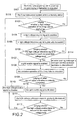
- Fig. 2 is a flowchart of a method of controlling the X-ray tube power system according to a first embodiment of the present disclosure
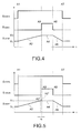
- Fig. 4 is a timing diagram of the X-ray tube power system according to a first embodiment of the present disclosure.
- a high voltage enable signal S HVEN is enabled (S104). That is, the high voltage enable signal S HVEN is converted from a low level to a high level at a time point A1 as shown in Fig. 4 .
- a high voltage reference signal S HVRF is gradually increased (S105).
- the high voltage reference signal S HVRF is gradually increased during a time interval A2. More specifically, the high voltage reference signal S HVRF is gradually increased from a lower limit voltage level V L after the high voltage enable signal S HVEN is enabled.
- the high voltage reference signal S HVRF is gradually increased during the time interval A2 in linear and time-invariant fashions.
- the embodiment is only exemplified but is not intended to limit the scope of the disclosure.
- the high voltage reference signal S HVRF can be increased in non-circular slope fashions.
- the high voltage reference signal S HVRF is typically set from zero volts to 3.3 volts, the lower limit voltage level V L is equal to zero volts and the upper limit voltage level V H is equal to 3.3 volts.
- the high voltage reference signal S HVRF from zero volts to 3.3 volts is corresponding to the high voltage of driving the X-ray tube from zero volts to 120 kilo-volts.
- the embodiment is only exemplified but is not intended to limit the scope of the disclosure.
- the step (S105) is executed, that is, the high voltage reference signal S HVRF is gradually increased.
- a grid enable signal S GDEN is enabled (S107).
- the grid enable signal S GDEN is converted from a low level to a high level at a time point A3. In other words, the operation of building high voltage of the X-ray tube power system is stable at this time.
- the time of increasing the high voltage reference signal S HVRF from the lower limit voltage level V L to the upper limit voltage level V H is about three seconds.
- the embodiment is only exemplified but is not intended to limit the scope of the disclosure.
- the emission operation of the X-ray tube is executed (S108).
- the emission operation of the X-ray tube is executed during a time interval A4. Afterward, it is to judge whether the emission operation of the X-ray tube is correctly completed (S109). If the emission operation of the X-ray tube is not yet correctly completed, an error warning message is provided and the emission operation of the X-ray tube is discontinued (S114). In other words, the emission operation of the X-ray tube is unavailable once the high voltage of driving the X-ray tube is decayed under the critical voltage.
- an error warning message is provided to notify the operator that the emission operation of the X-ray tube is failed and the emission operation of the X-ray tube is discontinued to avoid damaging the operator or the examinees.
- the grid enable signal S GDEN is disabled (S110).
- the grid enable signal S GDEN is converted from a high level to a low level at a time point A5.
- the high voltage reference signal S HVRF is gradually decreased (S111).
- the high voltage reference signal S HVRF is gradually decreased during a time interval A6. More specifically, the high voltage reference signal S HVRF is gradually increased from 3.3 volts after the high voltage enable signal S HVEN is disabled.
- the high voltage reference signal S HVRF is gradually increased during the time interval A6 in linear and time-invariant or RC discharging fashions.
- the embodiments are only exemplified but are not intended to limit the scope of the disclosure.
- the decay time of the RC discharging fashion is usually set to two to three seconds.
- the step (S111) is executed, that is, the high voltage reference signal S HVRF is gradually decreased.
- the high voltage enable signal S HVEN is disabled (S113). That is, the high voltage enable signal S HVEN is converted from a high level to a low level at a time point A7 as shown in Fig. 4 . Accordingly, a complete emission operation of the X-ray tube is completed.
- a protection time is provided between two emission operations to ensure safe emission operation of the X-ray tube. More specifically, as shown in Fig. 2 , after the step (S113) is finished, the step (S103) is executed, that is, it is to judge whether the high voltage operation of the X-ray tube is started up. Between the two steps, the protection time is provided to ensure safe emission operation of the X-ray tube. In particular, the protection time is set to at least ten seconds.
- the embodiment is only exemplified but is not intended to limit the scope of the disclosure.
- Fig. 5 is a timing diagram of the X-ray tube power system according to a second embodiment of the present disclosure.
- the major difference between the second embodiment and the first embodiment is that the high voltage reference signal S HVRF is increased to reach the upper limit voltage level V H at a time point A2', and the grid enable signal S GDEN is enabled after a buffer time tb.
- the buffer time tb is provided to ensure the X-ray tube is driven by the high voltage to produce X-ray.
- the high voltage reference signal S HVRF is increased to reach the upper limit voltage level V H at the time point A2'. In other words, the operation of building high voltage of the X-ray tube power system is stable at this time.
- the high voltage reference signal S HVRF is maintained at the upper limit voltage level V H during a time interval A2" to ensure safe emission operation of the X-ray tube.
- the grid enable signal S GDEN is converted from a low level to a high level at a time point A3 so that the emission operation of the X-ray tube is executed during a time interval A4.
- Fig. 6 is a timing diagram of the X-ray tube power system according to a third embodiment of the present disclosure.
- the major difference between the third embodiment and the first embodiment is that the high voltage enable signal S HVEN is converted from a low level to a high level at the time point A1, and the high voltage reference signal S HVRF is gradually increased after a delay time td. That is, the high voltage reference signal S HVRF is maintained at the lower limit voltage level V L during a time interval A1', and then the high voltage reference signal S HVRF is gradually increased until a time point A1".
- Fig. 3 is a flowchart of the method of controlling the X-ray tube power system according to a second embodiment of the present disclosure.
- Fig. 3 The major difference between Fig. 3 and Fig. 2 is that the step (S105) is executed after the high voltage enable signal S HVEN is enabled and the delay time td is provided (S104'). That is, the high voltage reference signal S HVRF is gradually increased after the high voltage enable signal S HVEN is enabled and the delay time td is provided. Accordingly, the X-ray tube power system can provide self-test function according to detection signals during the delay time td, thus increasing the reliability and stability of system operation.
- Fig. 7 is a timing diagram of the X-ray tube power system according to a fourth embodiment of the present disclosure.
- the major difference between the fourth embodiment and the first embodiment is that the high voltage enable signal S HVEN is converted from a low level to a high level at the time point A1 and the high voltage reference signal S HVRF is maintained at the lower limit voltage level V L during the time interval A1', and then the high voltage reference signal S HVRF is gradually increased until the time point A1".
- the high voltage reference signal S HVRF is increased to reach to the upper limit voltage level V H at a time point A2'. At this time, the operation of building high voltage of the X-ray tube power system is stable.
- the high voltage reference signal S HVRF is maintained at the upper limit voltage level V H during a time interval A2".
- the grid enable signal S GDEN is converted from a low level to a high level so that the emission operation of the X-ray tube is executed during a time interval A4.
- the fourth embodiment is substantially equal to the combination of the third embodiment and the second embodiment to provide both the delay time td and the buffer time tb.
- the X-ray tube power system includes an X-ray tube 50, an X-ray tube power 10, and a controller 20.
- the X-ray tube power 10 is provided to supply power to the X-ray tube 50.
- the X-ray tube power 10 is consisted of the above-mentioned grid transformer, the filament transformer, and the high-voltage generation circuit.
- the X-ray tube power 10 provides the required power to execute the emission operation of the X-ray tube 50.
- the controller 20 includes a voltage judgment unit 202 and a grid control unit 204.
- the voltage judgment unit 202 receives a high voltage reference signal S HVRF and an upper limit voltage level V H .
- the grid control unit 204 is connected to the voltage judgment unit 202.
- the grid control unit 204 When the voltage judgment unit 202 judges the high voltage reference signal S HVRF reaches to the upper limit voltage level V H , the grid control unit 204 outputs a grid enable signal S GDEN to execute the emission operation of the X-ray tube 50. Especially, when the high voltage operation of the X-ray tube 50 is started up and before the high voltage reference signal is gradually increased, a delay time can be provided so that the X-ray tube power system can provide self-test function according to detection signals during the delay time td, thus increasing the reliability and stability of system operation.
- the voltage judgment unit 202 further receives a lower limit voltage level V L .
- the high voltage reference signal S HVRF is gradually decreased.
- the controller 20 disables the high voltage enable signal S HVEN to discontinue the high voltage operation of the X-ray tube.
- a protection time is provided to ensure safe emission operation of the X-ray tube 50.
- the high voltage reference signal S HVRF is typically set from zero volts to 3.3 volts, the lower limit voltage level V L is equal to zero volts and the upper limit voltage level V H is equal to 3.3 volts. Also, the high voltage reference signal S HVRF from zero volts to 3.3 volts is corresponding to the high voltage of driving the X-ray tube from zero volts to 120 kilo-volts.
- the embodiment is only exemplified but is not intended to limit the scope of the disclosure.
- an error warning message is provided to notify the operator that the emission operation of the X-ray tube is failed and the emission operation of the X-ray tube is discontinued to avoid damaging the operator or the examinees.
Landscapes
- Health & Medical Sciences (AREA)
- General Health & Medical Sciences (AREA)
- Toxicology (AREA)
- X-Ray Techniques (AREA)
Abstract
A method of controlling a power system of an X-ray tube (50) is provided to supply power to the X-ray tube (50) and control the emission operation of the X-ray tube (50). The method includes following steps: First, it is to judge whether a high voltage operation of the X-ray tube (50) is started up (S103). Afterward, a high voltage reference signal (SHVRF) is gradually increased when the high voltage operation of the X-ray tube (50) is started up (S105). Afterward, it is to judge whether the high voltage reference signal (SHVRF) is increased to an upper limit voltage level (VH) (S106). Finally, the emission operation of the X-ray tube (50) is executed when the high voltage reference signal (SHVRF) is increased to the upper limit voltage level (VH) (S108).

Description
- The present disclosure relates generally to a power system and a method of controlling the same, and more particularly to a power system of an X-ray tube and a method of controlling the same.
- The power circuits of the X-ray tube is mainly composed of a main power circuit and a filament power circuit. The main power circuit is used to step up the external AC power voltage to produce a high voltage by a high-voltage transformer. The produced high voltage is applied between a cathode and an anode of the tube so that electrons generated from the cathode are struck on the anode to produce X-ray. The filament power circuit is used to step down the external AC power voltage to produce a low voltage by a filament transformer. The produced low voltage is applied between two terminals of the filament so that the filament can provide sufficient electrons by thermionic radiation.
- Because the X-ray tube beam is driven by the large voltage, the discharge phenomenon caused by instantaneous high voltage results in unstable electrical responses udder the high voltage operation, security concerns, and lifetime reduction of using the system.
- Accordingly, it is desirable to provide a power system of an X-ray tube and a method of controlling the same to stabilize electrical responses under the high voltage operation, ensure safe emission operation of the X-ray tube, and increase lifetime of using the system.
- An object of the present disclosure is to provide a power system of an X-ray tube to solve the above-mentioned problems. Accordingly, the X-ray tube power system includes an X-ray tube, an X-ray power, and a controller. The X-ray power is configured to supply power to the X-ray tube. The controller has a voltage judgment unit and a grid control unit. The voltage judgment unit is configured to receive a high voltage reference signal and an upper limit voltage level. The grid control unit is connected to the voltage judgment unit. The controller is configured to enable a high voltage enable signal and gradually increase the high voltage reference signal when a high voltage operation of the X-ray tube is started up by the X-ray power. The grid control unit is configured to output a grid enable signal to execute an emission operation of the X-ray tube when the voltage judgment unit is configured to judge that the high voltage reference signal is increased to the upper limit voltage level.
- Wherein the voltage judgment unit is further configured to receive a lower limit voltage level; the controller is configured to gradually reduce the high voltage reference signal when the emission operation of the X-ray tube is correctly completed; the controller is configured to disable the high voltage enable signal to discontinue the high voltage operation of the X-ray tube when the voltage judgment unit is configured to judge that the high voltage reference signal is reduced to the lower limit voltage level.
- Wherein when the high voltage operation of the X-ray tube is started up by the X-ray power, a delay time is provided before the high voltage reference signal is gradually increased.
- Wherein when the high voltage reference signal is reduced to the lower limit voltage level, a protection time is provided.
- Another object of the present disclosure is to provide a method of controlling a power system of an X-ray tube provided to supply power to an X-ray tube and control an emission operation of the X-ray tube to solve the above-mentioned problems. Accordingly, the method includes following steps: (a) judging whether a high voltage operation of the X-ray tube is started up; (b) gradually increasing a high voltage reference signal when the high voltage operation of the X-ray tube is started up; (c) judging whether the high voltage reference signal is increased to an upper limit voltage level; and (d) executing the emission operation of the X-ray tube when the high voltage reference signal is increased to the upper limit voltage level.
- Wherein after the step (d) further comprises: (e) judging whether the emission operation of the X-ray tube is correctly completed; (f) gradually decreasing the high voltage reference signal when the emission operation of the X-ray tube is correctly completed; (g) judging whether the high voltage reference signal is reduced to a lower limit voltage level; and (h) executing the step (a) when the high voltage reference signal is reduced to the lower limit voltage level.
- Wherein in the step (b), a high voltage enable signal is enabled to gradually increase the high voltage reference signal when the high voltage operation of the X-ray tube is started up; wherein after the step (c), the high voltage reference signal is continually increased when the high voltage reference signal is not yet reached to the upper limit voltage level; wherein in the step (d), a grid enable signal is enabled to execute the emission operation of the X-ray tube when the high voltage reference signal is increased to reach to the upper limit voltage level.
- Wherein in the step (f), the grid enable signal is disabled to gradually reduce the high voltage reference signal when the emission operation of the X-ray tube is correctly completed; wherein after the step (g), the high voltage reference signal is continually decreased when the high voltage reference signal is not yet reduced to the lower limit voltage level; wherein in the step (h), the high voltage enable signal is disabled and then the step (a) is executed when the high voltage reference signal is reduced to the lower limit voltage level.
- Wherein before the step (a), further comprising: (a01) powering on the X-ray tube power system and initializing the X-ray tube power system; and (a02) being the X-ray tube power system in a standby status.
- Wherein after the step (a), the step (a02) is executed when the high voltage operation of the X-ray tube is not yet started up.
- Wherein after the step (e), an error warning message is generated and then the step (a) is executed.
- Wherein in the step (b), when the high voltage operation of the X-ray tube is started up, a delay time is provided before the high voltage reference signal is gradually increased.
- Wherein in the step (h), when the high voltage reference signal is reduced to the lower limit voltage level, a protection time is provided before the step (a) is executed.
- Further another object of the present disclosure is to provide a method of controlling a power system of an X-ray tube provided to supply power to an X-ray tube and control an emission operation of the X-ray tube to solve the above-mentioned problems. Accordingly, the method includes following steps: (a) judging whether a high voltage operation of the X-ray tube is started up; (b) gradually increasing a high voltage reference signal when the high voltage operation of the X-ray tube is started up; (c) judging whether the high voltage reference signal is increased to an upper limit voltage level; (d) executing the emission operation of the X-ray tube when the high voltage reference signal is increased to the upper limit voltage level; (e) judging whether the emission operation of the X-ray tube is correctly completed; (f) gradually decreasing the high voltage reference signal when the emission operation of the X-ray tube is correctly completed; (g) judging whether the high voltage reference signal is reduced to a lower limit voltage level; and (h) executing the step (a) when the high voltage reference signal is reduced to the lower limit voltage level.
- It is to be understood that both the foregoing general description and the following detailed description are exemplary, and are intended to provide further explanation of the present disclosure as claimed. Other advantages and features of the present disclosure will be apparent from the following description, drawings and claims.
- The features of the present disclosure believed to be novel are set forth with particularity in the appended claims. The present disclosure itself, however, may be best understood by reference to the following detailed description of the present disclosure, which describes an exemplary embodiment of the present disclosure, taken in conjunction with the accompanying drawings, in which:
-
Fig. 1 is a schematic view of an X-ray tube power system according to the present disclosure; -
Fig. 2 is a flowchart of a method of controlling the X-ray tube power system according to a first embodiment of the present disclosure; -
Fig. 3 is a flowchart of the method of controlling the X-ray tube power system according to a second embodiment of the present disclosure; -
Fig. 4 is a timing diagram of the X-ray tube power system according to a first embodiment of the present disclosure; -
Fig. 5 is a timing diagram of the X-ray tube power system according to a second embodiment of the present disclosure; -
Fig. 6 is a timing diagram of the X-ray tube power system according to a third embodiment of the present disclosure; -
Fig. 7 is a timing diagram of the X-ray tube power system according to a fourth embodiment of the present disclosure; and -
Fig. 8 is a schematic block diagram of the X-ray tube power system according to the present disclosure. - Reference will now be made to the drawing figures to describe the present invention in detail.
- Reference is made to
Fig. 1 which is a schematic view of an X-ray tube power system according to the present disclosure. The X-ray tube power system mainly includes a grid transformer, a filament transformer, and a high voltage generation circuit. In particular, the X-ray tube is a transmission X-ray tube. The X-ray tube power system is electrically connected to anX-ray tube 50 and supply power to theX-ray tube 50. TheX-ray tube 50 has a cathode Tc and an anode Ta. The cathode Tc is usually a filament for producing electrons and the anode Ta is a tungsten target for providing an area on which that electrons strike. In addition, the space between the cathode Tc and the anode Ta maintains a vacuum in the tube. The grid transformer receives a first AC voltage and generates a positive voltage by a rectifying circuit and a filtering circuit. The filament transformer receives a second AC voltage and generates a negative voltage by another rectifying circuit and another filtering circuit. In addition, the filament transformer has further a secondary-side winding to provide the required voltage for preheating the cathode Tc of theX-ray tube 50. The high-voltage generation circuit generates a negative high voltage V-HV and a positive high voltage V+HV to supply power to the cathode Tc and the anode Ta of theX-ray tube 50, respectively, so as to accelerate the electron beam in the tube. The negative voltage outputted from the X-ray tube power system to suppress electron flow energy generated from the cathode Tc of the X-ray tube. Also, the positive voltage outputted from the X-ray tube power system to provide electron flow energy to the anode Ta of theX-ray tube 50 to produce X-ray. - Reference is made to
Fig. 2 which is a flowchart of a method of controlling the X-ray tube power system according to a first embodiment of the present disclosure; also reference is made toFig. 4 which is a timing diagram of the X-ray tube power system according to a first embodiment of the present disclosure. First, the X-ray tube power system is powered on and a setup initialization of the X-ray tube power system is executed (S101). After the setup initialization is completed, the X-ray tube power system enters a standby status (S102). Afterward, the X-ray tube power system judges whether a high voltage operation of the X-ray tube is started up (S103). If the high voltage operation of the X-ray tube is not started up, the X-ray tube power system is still in the standby status. When the high voltage operation of the X-ray tube is started up, a high voltage enable signal SHVEN is enabled (S104). That is, the high voltage enable signal SHVEN is converted from a low level to a high level at a time point A1 as shown inFig. 4 . After the high voltage enable signal SHVEN is enabled, a high voltage reference signal SHVRF is gradually increased (S105). Corresponding toFig. 4 , the high voltage reference signal SHVRF is gradually increased during a time interval A2. More specifically, the high voltage reference signal SHVRF is gradually increased from a lower limit voltage level VL after the high voltage enable signal SHVEN is enabled. - For convenience, the high voltage reference signal SHVRF is gradually increased during the time interval A2 in linear and time-invariant fashions. However, the embodiment is only exemplified but is not intended to limit the scope of the disclosure. In other words, the high voltage reference signal SHVRF can be increased in non-circular slope fashions. Afterward, it is to judge whether the high voltage reference signal SHVRF is increased to reach an upper limit voltage level VH (S106). Especially, because the high voltage reference signal SHVRF is typically set from zero volts to 3.3 volts, the lower limit voltage level VL is equal to zero volts and the upper limit voltage level VH is equal to 3.3 volts. Also, the high voltage reference signal SHVRF from zero volts to 3.3 volts is corresponding to the high voltage of driving the X-ray tube from zero volts to 120 kilo-volts. However, the embodiment is only exemplified but is not intended to limit the scope of the disclosure.
- If the high voltage reference signal SHVRF is not yet reached the upper limit voltage level VH, the step (S105) is executed, that is, the high voltage reference signal SHVRF is gradually increased. When the high voltage reference signal SHVRF is increased to reach the upper limit voltage level VH, a grid enable signal SGDEN is enabled (S107). Corresponding to
Fig. 4 , the grid enable signal SGDEN is converted from a low level to a high level at a time point A3. In other words, the operation of building high voltage of the X-ray tube power system is stable at this time. In general, the time of increasing the high voltage reference signal SHVRF from the lower limit voltage level VL to the upper limit voltage level VH is about three seconds. However, the embodiment is only exemplified but is not intended to limit the scope of the disclosure. When the grid enable signal SGDEN is enabled, the emission operation of the X-ray tube is executed (S108). Corresponding toFig. 4 , the emission operation of the X-ray tube is executed during a time interval A4. Afterward, it is to judge whether the emission operation of the X-ray tube is correctly completed (S109). If the emission operation of the X-ray tube is not yet correctly completed, an error warning message is provided and the emission operation of the X-ray tube is discontinued (S114). In other words, the emission operation of the X-ray tube is unavailable once the high voltage of driving the X-ray tube is decayed under the critical voltage. Accordingly, an error warning message is provided to notify the operator that the emission operation of the X-ray tube is failed and the emission operation of the X-ray tube is discontinued to avoid damaging the operator or the examinees. When the emission operation of the X-ray tube is correctly completed, the grid enable signal SGDEN is disabled (S110). Corresponding toFig. 4 , the grid enable signal SGDEN is converted from a high level to a low level at a time point A5. - When the grid enable signal SGDEN is disabled, the high voltage reference signal SHVRF is gradually decreased (S111). Corresponding to
Fig. 4 , the high voltage reference signal SHVRF is gradually decreased during a time interval A6. More specifically, the high voltage reference signal SHVRF is gradually increased from 3.3 volts after the high voltage enable signal SHVEN is disabled. In this embodiment, the high voltage reference signal SHVRF is gradually increased during the time interval A6 in linear and time-invariant or RC discharging fashions. However, the embodiments are only exemplified but are not intended to limit the scope of the disclosure. In particular, the decay time of the RC discharging fashion is usually set to two to three seconds. - Afterward, it is to judge whether the high voltage enable signal SHVEN is reduced to the lower limit voltage level VL (S112). If the high voltage reference signal SHVRF is not yet reduced to the lower limit voltage level VL, the step (S111) is executed, that is, the high voltage reference signal SHVRF is gradually decreased. When the high voltage reference signal SHVRF is reduced to the lower limit voltage level VL, the high voltage enable signal SHVEN is disabled (S113). That is, the high voltage enable signal SHVEN is converted from a high level to a low level at a time point A7 as shown in
Fig. 4 . Accordingly, a complete emission operation of the X-ray tube is completed. Especially, in order to avoid continuously executing two emission operations in a short time, a protection time is provided between two emission operations to ensure safe emission operation of the X-ray tube. More specifically, as shown inFig. 2 , after the step (S113) is finished, the step (S103) is executed, that is, it is to judge whether the high voltage operation of the X-ray tube is started up. Between the two steps, the protection time is provided to ensure safe emission operation of the X-ray tube. In particular, the protection time is set to at least ten seconds. However, the embodiment is only exemplified but is not intended to limit the scope of the disclosure. - Reference is made to
Fig. 5 which is a timing diagram of the X-ray tube power system according to a second embodiment of the present disclosure. The major difference between the second embodiment and the first embodiment is that the high voltage reference signal SHVRF is increased to reach the upper limit voltage level VH at a time point A2', and the grid enable signal SGDEN is enabled after a buffer time tb. In particular, the buffer time tb is provided to ensure the X-ray tube is driven by the high voltage to produce X-ray. Corresponding toFig. 5 , the high voltage reference signal SHVRF is increased to reach the upper limit voltage level VH at the time point A2'. In other words, the operation of building high voltage of the X-ray tube power system is stable at this time. In addition, the high voltage reference signal SHVRF is maintained at the upper limit voltage level VH during a time interval A2" to ensure safe emission operation of the X-ray tube. Furthermore, the grid enable signal SGDEN is converted from a low level to a high level at a time point A3 so that the emission operation of the X-ray tube is executed during a time interval A4. - Reference is made to
Fig. 6 which is a timing diagram of the X-ray tube power system according to a third embodiment of the present disclosure. The major difference between the third embodiment and the first embodiment is that the high voltage enable signal SHVEN is converted from a low level to a high level at the time point A1, and the high voltage reference signal SHVRF is gradually increased after a delay time td. That is, the high voltage reference signal SHVRF is maintained at the lower limit voltage level VL during a time interval A1', and then the high voltage reference signal SHVRF is gradually increased until a time point A1". Reference is made toFig. 3 which is a flowchart of the method of controlling the X-ray tube power system according to a second embodiment of the present disclosure. The major difference betweenFig. 3 andFig. 2 is that the step (S105) is executed after the high voltage enable signal SHVEN is enabled and the delay time td is provided (S104'). That is, the high voltage reference signal SHVRF is gradually increased after the high voltage enable signal SHVEN is enabled and the delay time td is provided. Accordingly, the X-ray tube power system can provide self-test function according to detection signals during the delay time td, thus increasing the reliability and stability of system operation. - Reference is made to
Fig. 7 which is a timing diagram of the X-ray tube power system according to a fourth embodiment of the present disclosure. The major difference between the fourth embodiment and the first embodiment is that the high voltage enable signal SHVEN is converted from a low level to a high level at the time point A1 and the high voltage reference signal SHVRF is maintained at the lower limit voltage level VL during the time interval A1', and then the high voltage reference signal SHVRF is gradually increased until the time point A1". In particular, the high voltage reference signal SHVRF is increased to reach to the upper limit voltage level VH at a time point A2'. At this time, the operation of building high voltage of the X-ray tube power system is stable. Also, the high voltage reference signal SHVRF is maintained at the upper limit voltage level VH during a time interval A2". Until a time point A3, the grid enable signal SGDEN is converted from a low level to a high level so that the emission operation of the X-ray tube is executed during a time interval A4. In other words, the fourth embodiment is substantially equal to the combination of the third embodiment and the second embodiment to provide both the delay time td and the buffer time tb. - Reference is made to
Fig. 8 which is a schematic block diagram of the X-ray tube power system according to the present disclosure. The X-ray tube power system includes anX-ray tube 50, anX-ray tube power 10, and acontroller 20. TheX-ray tube power 10 is provided to supply power to theX-ray tube 50. In particular, theX-ray tube power 10 is consisted of the above-mentioned grid transformer, the filament transformer, and the high-voltage generation circuit. In other words, theX-ray tube power 10 provides the required power to execute the emission operation of theX-ray tube 50. - The
controller 20 includes avoltage judgment unit 202 and agrid control unit 204. Thevoltage judgment unit 202 receives a high voltage reference signal SHVRF and an upper limit voltage level VH. Thegrid control unit 204 is connected to thevoltage judgment unit 202. First, the X-ray tube power system is powered on and a setup initialization of the X-ray tube power system is executed. After the setup initialization is completed, the X-ray tube power system enters a standby status. When theX-ray tube power 10 starts up the high voltage operation of theX-ray tube 50, thecontroller 20 enables a high voltage enable signal SHVEN and gradually increases the high voltage reference signal SHVRF. When thevoltage judgment unit 202 judges the high voltage reference signal SHVRF reaches to the upper limit voltage level VH, thegrid control unit 204 outputs a grid enable signal SGDEN to execute the emission operation of theX-ray tube 50. Especially, when the high voltage operation of theX-ray tube 50 is started up and before the high voltage reference signal is gradually increased, a delay time can be provided so that the X-ray tube power system can provide self-test function according to detection signals during the delay time td, thus increasing the reliability and stability of system operation. - In addition, the
voltage judgment unit 202 further receives a lower limit voltage level VL. When the emission operation of theX-ray tube 50 is correctly completed, the high voltage reference signal SHVRF is gradually decreased. When thevoltage judgment unit 202 judges the high voltage reference signal SHVRF is reduced to the lower limit voltage level VL, thecontroller 20 disables the high voltage enable signal SHVEN to discontinue the high voltage operation of the X-ray tube. Especially, when the high voltage reference signal is reduced to the lower limit voltage level VL and before the X-ray tube power system is executed again, a protection time is provided to ensure safe emission operation of theX-ray tube 50. - Because the high voltage reference signal SHVRF is typically set from zero volts to 3.3 volts, the lower limit voltage level VL is equal to zero volts and the upper limit voltage level VH is equal to 3.3 volts. Also, the high voltage reference signal SHVRF from zero volts to 3.3 volts is corresponding to the high voltage of driving the X-ray tube from zero volts to 120 kilo-volts. However, the embodiment is only exemplified but is not intended to limit the scope of the disclosure.
- Especially, if the emission operation of the X-ray tube is not yet correctly completed, an error warning message is provided to notify the operator that the emission operation of the X-ray tube is failed and the emission operation of the X-ray tube is discontinued to avoid damaging the operator or the examinees.
- In conclusion, the present disclosure has following advantages:
- 1. Comparing to the prior art emission operation of the X-ray tube, the high voltage reference signal SHVRF is gradually and smoothly increased from the lower limit voltage level VL to the upper limit voltage level VH to avoid the discharge phenomenon caused by instantaneous high voltage, thus stabilizing electrical responses under the high voltage operation, ensuring safe emission operation, and increasing lifetime of using the system;
- 2. The delay time td is provided to provide self-test function according to detection signals during the delay time td, thus increasing the reliability and stability of system operation;
- 3. The buffer time tb is provided to ensure the X-ray tube is driven by the high voltage to produce X-ray;
- 4. The protection time is provided to ensure safe emission operation of the X-ray tube; and
- 5. If the emission operation of the X-ray tube is not yet correctly completed, an error warning message is provided to notify the operator that the emission operation of the X-ray tube is failed and the emission operation of the X-ray tube is discontinued to avoid damaging the operator or the examinees.
Claims (14)
- An X-ray tube power system comprising:an X-ray tube (50);an X-ray power (10) configured to supply power to the X-ray tube (50); anda controller (20) comprising:a voltage judgment unit (202) configured to receive a high voltage reference signal (SHVRF) and an upper limit voltage level (VH); anda grid control unit (204) connected to the voltage judgment unit (202);wherein the controller (20) is configured to enable a high voltage enable signal (SHVEN) and gradually increase the high voltage reference signal (SHVRF) when a high voltage operation of the X-ray tube (50) is started up by the X-ray power (10); the grid control unit (204) is configured to output a grid enable signal (SGDEN) to execute an emission operation of the X-ray tube (50) when the voltage judgment unit (202) is configured to judge that the high voltage reference signal (SHVRF) is increased to the upper limit voltage level (VH).
- The X-ray tube power system in claim 1, wherein the voltage judgment unit (202) is further configured to receive a lower limit voltage level (VL); the controller (20) is configured to gradually reduce the high voltage reference signal (SHVRF) when the emission operation of the X-ray tube (50) is correctly completed; the controller (20) is configured to disable the high voltage enable signal (SHVEN) to discontinue the high voltage operation of the X-ray tube (50) when the voltage judgment unit (202) is configured to judge that the high voltage reference signal (SHVRF) is reduced to the lower limit voltage level (VL).
- The X-ray tube power system in claim 1, wherein when the high voltage operation of the X-ray tube (50) is started up by the X-ray power (10), a delay time (td) is provided before the high voltage reference signal (SHVRF) is gradually increased.
- The X-ray tube power system in claim 2, wherein when the high voltage reference signal (SHVRF) is reduced to the lower limit voltage level (VL), a protection time is provided.
- A method of controlling a power system of an X-ray tube (50) provided to supply power to an X-ray tube (50) and control an emission operation of the X-ray tube (50), the method comprising following steps:(a) judging whether a high voltage operation of the X-ray tube (50) is started up (S103);(b) gradually increasing a high voltage reference signal (SHVRF) when the high voltage operation of the X-ray tube (50) is started up (S105);(c) judging whether the high voltage reference signal (SHVRF) is increased to an upper limit voltage level (VH) (S106); and(d) executing the emission operation of the X-ray tube (50) when the high voltage reference signal (SHVRF) is increased to the upper limit voltage level (VH) (S108).
- The method of controlling the power system of the X-ray tube (50) in claim 5, wherein after the step (d) further comprises:(e) judging whether the emission operation of the X-ray tube (50) is correctly completed (S109);(f) gradually decreasing the high voltage reference signal (SHVRF) when the emission operation of the X-ray tube (50) is correctly completed (S111);(g) judging whether the high voltage reference signal (SHVRF) is reduced to a lower limit voltage level (VL) (S112); and(h) executing the step (a) when the high voltage reference signal (SHVRF) is reduced to the lower limit voltage level (VL).
- The method of controlling the power system of the X-ray tube (50) in claim 5, wherein in the step (b), a high voltage enable signal (SHVEN) is enabled to gradually increase the high voltage reference signal (SHVRF) when the high voltage operation of the X-ray tube (50) is started up (S104); wherein after the step (c), the high voltage reference signal (SHVRF) is continually increased when the high voltage reference signal (SHVRF) is not yet reached to the upper limit voltage level (VH); wherein in the step (d), a grid enable signal (SGDEN) is enabled to execute the emission operation of the X-ray tube (50) when the high voltage reference signal (SHVRF) is increased to reach to the upper limit voltage level (VH) (S107).
- The method of controlling the power system of the X-ray tube (50) in claim 6, wherein in the step (f), the grid enable signal (SGDEN) is disabled to gradually reduce the high voltage reference signal (SHVRF) when the emission operation of the X-ray tube (50) is correctly completed (S110); wherein after the step (g), the high voltage reference signal (SHVRF) is continually decreased when the high voltage reference signal (SHVRF) is not yet reduced to the lower limit voltage level (VL); wherein in the step (h), the high voltage enable signal (SHVEN) is disabled (S113) and then the step (a) is executed when the high voltage reference signal (SHVRF) is reduced to the lower limit voltage level (VL).
- The method of controlling the power system of the X-ray tube (50) in claim 5, wherein before the step (a), further comprising:(a01) powering on the X-ray tube power system and initializing the X-ray tube power system (S101); and(a02) being the X-ray tube power system in a standby status (S102).
- The method of controlling the power system of the X-ray tube (50) in claim 9, wherein after the step (a), the step (a02) is executed when the high voltage operation of the X-ray tube (50) is not yet started up.
- The method of controlling the power system of the X-ray tube (50) in claim 6, wherein after the step (e), an error warning message is generated (S114) and then the step (a) is executed.
- The method of controlling the power system of the X-ray tube (50) in claim 5, wherein in the step (b), when the high voltage operation of the X-ray tube (50) is started up, a delay time (td) is provided (S104') before the high voltage reference signal (SHVRF) is gradually increased.
- The method of controlling the power system of the X-ray tube (50) in claim 8, wherein in the step (h), when the high voltage reference signal (SHVRF) is reduced to the lower limit voltage level (VL), a protection time is provided before the step (a) is executed.
- A method of controlling a power system of an X-ray tube (50) provided to supply power to an X-ray tube (50) and control an emission operation of the X-ray tube (50), the method comprising following steps:(a) judging whether a high voltage operation of the X-ray tube (50) is started up (S103);(b) gradually increasing a high voltage reference signal (SHVRF) when the high voltage operation of the X-ray tube (50) is started up (S105);(c) judging whether the high voltage reference signal (SHVRF) is increased to an upper limit voltage level (VH) (S106);(d) executing the emission operation of the X-ray tube (50) when the high voltage reference signal (SHVRF) is increased to the upper limit voltage level (VH) (S108);(e) judging whether the emission operation of the X-ray tube (50) is correctly completed (S109);(f) gradually decreasing the high voltage reference signal (SHVRF) when the emission operation of the X-ray tube (50) is correctly completed (S111);(g) judging whether the high voltage reference signal (SHVRF) is reduced to a lower limit voltage level (VL) (S112); and(h) executing the step (a) when the high voltage reference signal (SHVRF) is reduced to the lower limit voltage level (VL).
Applications Claiming Priority (1)
| Application Number | Priority Date | Filing Date | Title |
|---|---|---|---|
| TW102139898A TWI489912B (en) | 2013-11-04 | 2013-11-04 | Power system of x-ray tube and method of controlling the same |
Publications (1)
| Publication Number | Publication Date |
|---|---|
| EP2869673A1 true EP2869673A1 (en) | 2015-05-06 |
Family
ID=50071480
Family Applications (1)
| Application Number | Title | Priority Date | Filing Date |
|---|---|---|---|
| EP20140154535 Withdrawn EP2869673A1 (en) | 2013-11-04 | 2014-02-10 | Power system of x-ray tube and method of controlling the same |
Country Status (3)
| Country | Link |
|---|---|
| US (1) | US20150124932A1 (en) |
| EP (1) | EP2869673A1 (en) |
| TW (1) | TWI489912B (en) |
Cited By (1)
| Publication number | Priority date | Publication date | Assignee | Title |
|---|---|---|---|---|
| CN110545611A (en) * | 2019-08-09 | 2019-12-06 | 北京纳米维景科技有限公司 | Method for realizing grid control isolation and grid control circuit |
Families Citing this family (1)
| Publication number | Priority date | Publication date | Assignee | Title |
|---|---|---|---|---|
| EP2991094A1 (en) * | 2014-09-01 | 2016-03-02 | LightLab Sweden AB | X-ray source and system comprising an x-ray source |
Citations (3)
| Publication number | Priority date | Publication date | Assignee | Title |
|---|---|---|---|---|
| JPS5958798A (en) * | 1982-09-28 | 1984-04-04 | Toshiba Corp | Device for judging deterioration of x-ray tube |
| US20040109537A1 (en) * | 2001-03-29 | 2004-06-10 | Tsutomu Nakamura | X -ray generator |
| CN101754560A (en) * | 2008-12-12 | 2010-06-23 | 东软飞利浦医疗设备系统有限责任公司 | grid modulator |
Family Cites Families (10)
| Publication number | Priority date | Publication date | Assignee | Title |
|---|---|---|---|---|
| US3325645A (en) * | 1964-08-11 | 1967-06-13 | Picker X Ray Corp Waite Mfg | X-ray tube system with voltage and current control means |
| US5339349A (en) * | 1992-10-26 | 1994-08-16 | Xeno Millan Y | Portable x-ray unit |
| US5400385A (en) * | 1993-09-02 | 1995-03-21 | General Electric Company | High voltage power supply for an X-ray tube |
| KR20040102366A (en) * | 2002-04-24 | 2004-12-04 | 하마마츠 포토닉스 가부시키가이샤 | X-ray tube operating state acquiring device, x-ray tube operating state acquiring system, and x-ray tube operating state acquiring method |
| CN101765290B (en) * | 2009-12-07 | 2012-12-26 | 芜湖国睿兆伏电子股份有限公司 | High-voltage generator used for X-ray machine and control method thereof |
| CN101702864B (en) * | 2009-12-08 | 2013-03-13 | 东文高压电源(天津)有限公司 | High-voltage power supply special for X-ray tube |
| JP5661432B2 (en) * | 2010-11-17 | 2015-01-28 | キヤノン株式会社 | X-ray generator |
| JP5984367B2 (en) * | 2011-12-02 | 2016-09-06 | キヤノン株式会社 | Radiation generator and radiation imaging system using the same |
| CN202721888U (en) * | 2012-08-03 | 2013-02-06 | 合肥美亚光电技术股份有限公司 | Pulse X ray generator |
| JP2014107158A (en) * | 2012-11-28 | 2014-06-09 | Canon Inc | Radiation generator |
-
2013
- 2013-11-04 TW TW102139898A patent/TWI489912B/en active
-
2014
- 2014-02-07 US US14/175,124 patent/US20150124932A1/en not_active Abandoned
- 2014-02-10 EP EP20140154535 patent/EP2869673A1/en not_active Withdrawn
Patent Citations (4)
| Publication number | Priority date | Publication date | Assignee | Title |
|---|---|---|---|---|
| JPS5958798A (en) * | 1982-09-28 | 1984-04-04 | Toshiba Corp | Device for judging deterioration of x-ray tube |
| US20040109537A1 (en) * | 2001-03-29 | 2004-06-10 | Tsutomu Nakamura | X -ray generator |
| CN101754560A (en) * | 2008-12-12 | 2010-06-23 | 东软飞利浦医疗设备系统有限责任公司 | grid modulator |
| CN101754560B (en) * | 2008-12-12 | 2012-05-23 | 东软飞利浦医疗设备系统有限责任公司 | Grid modulator |
Non-Patent Citations (1)
| Title |
|---|
| DATABASE WPI Week 201053, Derwent World Patents Index; AN 2010-J65068, XP002726329 * |
Cited By (1)
| Publication number | Priority date | Publication date | Assignee | Title |
|---|---|---|---|---|
| CN110545611A (en) * | 2019-08-09 | 2019-12-06 | 北京纳米维景科技有限公司 | Method for realizing grid control isolation and grid control circuit |
Also Published As
| Publication number | Publication date |
|---|---|
| TWI489912B (en) | 2015-06-21 |
| TW201519699A (en) | 2015-05-16 |
| US20150124932A1 (en) | 2015-05-07 |
Similar Documents
| Publication | Publication Date | Title |
|---|---|---|
| JP5637688B2 (en) | Inverter device and X-ray high voltage device using the inverter device | |
| US6760234B2 (en) | DC power supply apparatus for a plasma generating apparatus | |
| CN105866602B (en) | A high voltage direct current transmission converter valve commutation failure protection device | |
| CN103746570B (en) | Rectifier and electric power equipment | |
| US11128213B2 (en) | Inverter circuit and X-ray radiation device | |
| US20150124932A1 (en) | Power system of x-ray tube and method of controlling the same | |
| JP5255189B2 (en) | Power supply device and high-frequency circuit system | |
| JP5158582B2 (en) | Power supply device and high-frequency circuit system | |
| JP2017225328A (en) | Device and method for protecting dc source | |
| JP4796855B2 (en) | Power supply device and high-frequency circuit system | |
| US9374881B2 (en) | Radiation generator including cut-off voltage generator and associated detection unit | |
| US9192036B2 (en) | Power apparatus for X-ray tube, power system with the power apparatus, and method of operating the same | |
| CN110224580B (en) | Digital power supply starting method, starting circuit and digital power supply | |
| JP2005116355A (en) | Microwave tube system and microwave tube | |
| CN115207876B (en) | Overvoltage protection circuit, method and power supply system | |
| JPH11204289A (en) | Pulse X-ray equipment | |
| CN213027822U (en) | Switching power supply constant current circuit, switching power supply chip and shutdown circuit | |
| EP1531540A2 (en) | Power supply device | |
| JP2001095242A (en) | Power supply | |
| JP3278293B2 (en) | X-ray generation prevention circuit for video equipment | |
| US8120270B2 (en) | Circuit arrangement and method for operating a discharge lamp with preheatable electrodes | |
| CN216564556U (en) | Charging system of lithium battery | |
| JPH11329784A (en) | Inverter type X-ray high voltage device | |
| KR20200012609A (en) | Apparatus for controlling compressor, control system for compressor and method for controlling compressor | |
| JP2748695B2 (en) | High-voltage generation circuit for television receiver |
Legal Events
| Date | Code | Title | Description |
|---|---|---|---|
| PUAI | Public reference made under article 153(3) epc to a published international application that has entered the european phase |
Free format text: ORIGINAL CODE: 0009012 |
|
| 17P | Request for examination filed |
Effective date: 20140210 |
|
| AK | Designated contracting states |
Kind code of ref document: A1 Designated state(s): AL AT BE BG CH CY CZ DE DK EE ES FI FR GB GR HR HU IE IS IT LI LT LU LV MC MK MT NL NO PL PT RO RS SE SI SK SM TR |
|
| AX | Request for extension of the european patent |
Extension state: BA ME |
|
| STAA | Information on the status of an ep patent application or granted ep patent |
Free format text: STATUS: THE APPLICATION IS DEEMED TO BE WITHDRAWN |
|
| 18D | Application deemed to be withdrawn |
Effective date: 20151107 |