EP2869607A1 - Wireless communication system, method, user equipment, node and computer program product - Google Patents
Wireless communication system, method, user equipment, node and computer program product Download PDFInfo
- Publication number
- EP2869607A1 EP2869607A1 EP20130290267 EP13290267A EP2869607A1 EP 2869607 A1 EP2869607 A1 EP 2869607A1 EP 20130290267 EP20130290267 EP 20130290267 EP 13290267 A EP13290267 A EP 13290267A EP 2869607 A1 EP2869607 A1 EP 2869607A1
- Authority
- EP
- European Patent Office
- Prior art keywords
- mcch
- multicast
- channel
- user equipment
- mbsfn
- Prior art date
- Legal status (The legal status is an assumption and is not a legal conclusion. Google has not performed a legal analysis and makes no representation as to the accuracy of the status listed.)
- Granted
Links
Images


Classifications
-
- H—ELECTRICITY
- H04—ELECTRIC COMMUNICATION TECHNIQUE
- H04W—WIRELESS COMMUNICATION NETWORKS
- H04W4/00—Services specially adapted for wireless communication networks; Facilities therefor
- H04W4/06—Selective distribution of broadcast services, e.g. multimedia broadcast multicast service [MBMS]; Services to user groups; One-way selective calling services
-
- H—ELECTRICITY
- H04—ELECTRIC COMMUNICATION TECHNIQUE
- H04W—WIRELESS COMMUNICATION NETWORKS
- H04W72/00—Local resource management
- H04W72/30—Resource management for broadcast services
-
- H—ELECTRICITY
- H04—ELECTRIC COMMUNICATION TECHNIQUE
- H04W—WIRELESS COMMUNICATION NETWORKS
- H04W72/00—Local resource management
- H04W72/04—Wireless resource allocation
- H04W72/044—Wireless resource allocation based on the type of the allocated resource
- H04W72/0446—Resources in time domain, e.g. slots or frames
Definitions
- the present invention relates to wireless communications, and more particularly although not exclusively, to transmission and reception of messages relating to a multimedia broadcast/multicast service (MBMS).
- MBMS multimedia broadcast/multicast service
- MBMS multimedia broadcast multicast services
- transmission for an MBMS occurs over two channels: a multicast control channel (MCCH) and a multicast traffic channel (MTCH).
- MCCH multicast control channel
- MTCH multicast traffic channel
- the MTCH delivers content of the MBMS
- the MCCH delivers control information related to the MBMS.
- the MCCH might include key control information that specifies how the content in the MTCH is to be delivered for example, and MCCH channels are used as point-to-multipoint downlink channels to transmit MCCH information.
- one cell has one corresponding MCCH.
- an enhanced version of MBMS (eMBMS), referred to as Multicast-Broadcast Single-Frequency Network (MBSFN), supports broadcast only services.
- MBSFN areas can be defined, each having an MCCH channel to transmit MCCH information to all UEs in the MBSFN area in question.
- MBMS information on the MCCH channel is transmitted according to a fixed schedule, which is common for all services. Thus, the majority of MCCH information is transmitted periodically based on a repetition period. This MCCH information is repeated a configurable number of times with exactly the same content. The time period in which the content of this MCCH information remains unchanged is called the 'modification period'.
- a method performed in a wireless telecommunication system providing communication services to multiple user equipment (UE) devices across multiple cells of the system and supporting broadcast information services in one or more multimedia-broadcast multicast-service single frequency network (MBSFN) areas of the system, comprising providing a first point-to-multipoint multicast control channel (MCCH) and at least one additional MCCH channel per MBSFN area.
- MCCH point-to-multipoint multicast control channel
- a periodicity for the at least one additional MCCH can be selected that is different to the periodicity of the first MCCH of the MBSFN area.
- the modification period of the at least one additional MCCH in an MBSFN area can be configured to a lower value than the modification period of the first MCCH channel for the area.
- the at least one additional MCCH channel can be configured independently of the first MCCH channel for an area.
- Multiple multicast traffic channels (MTCHs) belonging to different MCCHs can be transmitted in the same physical multicast channel (PMCH) in a transmission time interval (TTI).
- Radio resource can be partitioned at the subframe level for the scheduling of MTCHs belonging to different MCCHs.
- a method for supporting point-to-multipoint multicast communication with multiple UE devices in a wireless telecommunication system comprising providing a first multicast control channel (MCCH) for use with the multiple UEs with a first modification period, providing a second MCCH for use with at least a subset of the multiple UEs.
- the second MCCH can have a second modification period that is smaller than the first modification period.
- the first MCCH can be an unmodified control channel for the system.
- the first MCCH can be used in connection with transmission of a first type of service, and the at least one additional MCCH is used in connection with transmission for a public safety service.
- MCCH multicast control channel
- a wireless telecommunication system operable to provide communication services to multiple user equipment (UE) devices across multiple cells of the system and to support broadcast information services in one or more multimedia-broadcast multicast-service single frequency network (MBSFN) areas of the system, the system including a node operable to communicate with user equipment using a first point-to-multipoint multicast control channel (MCCH) and at least one additional MCCH channel per MBSFN area.
- UE user equipment
- MBSFN multimedia-broadcast multicast-service single frequency network
- a node in a wireless telecommunication system operable to provide communication services to multiple user equipment (UE) devices across multiple cells of the system and to support broadcast information services in one or more multimedia-broadcast multicast-service single frequency network (MBSFN) areas of the system, the node operable to communicate with user equipment using a first point-to-multipoint multicast control channel (MCCH) and at least one additional MCCH channel per MBSFN area.
- the node can be operable to configure a periodicity for the at least one additional MCCH that is different to the periodicity of the first MCCH of the MBSFN area.
- a computer program product comprising a computer usable medium having computer readable program code embodied therein, said computer readable program code adapted to be executed to implement a method, in a wireless telecommunication system, as provided above.
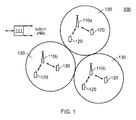
- FIG. 1 is a schematic representation of a wireless telecommunication system 100, which may be an LTE network or some other wireless network, according to an example.
- Wireless network 100 may include a number of evolved Node Bs (eNBs) 110 and other network entities. For simplicity, only three eNBs 110a, 110b and 110c and one network controller 141 are shown in figure 1 .
- An eNB communicates with UEs 120.
- Each eNB 110 provides communication coverage for a particular geographic area (cell) 130 and supports communication for the UEs located within the coverage area of the cell. While such cells 130 are depicted as having non-overlapping coverage areas, persons of ordinary skill in the art will recognize that one or more of the cells 130 may have partially overlapping coverage with adjacent cells.
- UEs 120 may be dispersed throughout the system 100, and UEs can be stationary or mobile.
- a UE communicates with an eNB via the downlink and uplink.
- the downlink refers to the communication link from the eNB to the UE
- the uplink refers to the communication link from the UE to the eNB.
- Bi-directional communication between an eNB and a UE is depicted in figure 1 by a solid line with double arrows.
- Wireless network 100 may support MBMS services for multiple UEs as well as unicast services for individual UEs.
- An MBMS service may be a broadcast service or a multicast service.
- MBMS services may be supported with a multi-cell mode, a single-cell mode, and/or other modes.
- MMSFN multimedia broadcast single frequency network
- a cell may send a MBSFN transmission by itself.
- a broadcast control channel can carry system information blocks (SIBs), with each SIB including certain system information pertinent for communicating with and/or receiving data from a cell.
- the MCCH may carry control information used to receive MBMS services, such as a list of MBMS services with ongoing sessions, information used to receive the MTCH, and so on.
- the MTCH may carry data for MBMS services.
- the enhanced MBMS (eMBMS) procedure can provide a suitable approach for the support of group communication from radio resource efficiency perspectives, since group communication typically requires the transmission of the same information to a large number of receiving group members.
- group communication has certain latency requirements that may need to be satisfied in order to make it viable.
- One such requirement is on the end-to-end setup delay. Typically, this should satisfy 300ms.
- an eMBMS procedure uses the multicast control channel (MCCH) to inform the bearer configuration of new media.
- the MCCH can only be modified at an MCCH modification boundary, which is set to 5.12s or 10.2 sec. A 5-10s delay cannot be tolerable in respect of group communication in emergency public safety communications scenarios.
- multiple MCCHs can be provided, with at least one of the multiple channels being defined with a relatively small MCCH modification period for use in group communication for applications such as public safety.
- the modification period can be defined to be as small as 10ms.
- Multicast-broadcast single-frequency network is a transmission mode which exploits LTE's OFDM radio interface to send multicast or broadcast data as a multi-cell transmission over a synchronized single-frequency network (SFN).
- An MBSFN transmission appears to a UE 120 as a transmission from a single large cell.
- MCCH can be configured per MBSFN area. According to an example however, more than one MCCH is configured for an MBSFN area.
- the first MCCH configuration is unmodified from the legacy system.
- Second, third and so on MCCHs are configured independently from the first MCCH. Also the configuration is performed such that the physical resources associated with first and second MCCH do not collide. Additionally, an MCCH change notification is used unmodified for the first MCCH change. The second, third and so on MCCHs are not considered within the MCCH change notification.
- a UE supporting group communication for public safety monitors the MCCH in a periodic manner to acquire the MCCH changes.
- SIBs System Information Blocks
- the information element SIB13 provides the information required for decoding of the MCCH and for acquiring the MBMS control information associated with one or more MBSFN areas, and is structured as follows:
- MBSFN-AreaInfoList carries the information on MCCH configuration per MBSFN area, and thus contains the information required to acquire the MBMS control information associated with one or more MBSFN areas.
- a typical signalling format is as follows:
- multiple MCCHs are provided per MBSFN area.
- the second, third and so on MCCH configurations can be signalled in MBSFN-AreaInfoList IE following the legacy signalling structure.
- the modification (bold) to introduce a second MCCH is as follows:
- the first MCCH can be used in connection with transmission of a first type of service, such as a TV service for example.
- An additional MCCH can be used in connection with transmission for another service, such as a public safety service for example.
- MCCH can only be modified at the MCCH modification boundary, which is currently set to 5.12s or 10.2 sec. These values are not tolerable for group communication in emergency public safety communications.
- At least one additional MCCH is provided with a modification period that is defined to have a value that is lower than the legacy case, such as a value within the range 1ms to 5.12s or 10.2s for example.
- the UE procedure is modified such that the UE is required to monitor MCCH at the MCCH modification boundary in an example.
- a delta information transmission compared to the first MCCH configuration can be provided. That is, only parameter values which are different from the first (legacy) MCCH are transmitted for any additional MCCH.
- a UE decoding both first and the second (or further) MCCH configuration data can realise the full configuration for the second (and so on) MCCH.
- radio waveform will be corrupted and any receiving UEs will therefore not be able to receive data correctly. This is therefore a waste of radio resources.
- the avoidance of physical resource collision can be avoided in two ways.
- the radio resource for MTCH transmission is scheduled via the MCH scheduling information MAC CE, which is a MAC command transmitted at the beginning of the MCH scheduling period.
- the physical resource scheduled for a particular MTCH is informed with the indication of the start subframe and end subframe.
- Figure 1 is a schematic representation of the format used for MCH scheduling information MAC control element.
- LCID is the logical channel ID of the MTCH.
- the length of the field is 5 bits. In the example of figure 1 , multiple LCIDs are depicted (LCID1 (101), LCID2 (103)...LCIDn (105)).
- the stop MTCH field (107, 109, 111) indicates the ordinal number of the subframe within the MCH scheduling period, counting only the subframes allocated to the MCH, where the corresponding MTCH stops. Value 0 corresponds to the first subframe.
- the length of the field is 11 bits.
- the special Stop MTCH value 2047 indicates that the corresponding MTCH is not scheduled.
- the value range 2043 to 2046 is reserved.
- radio resource collision can be avoided via scheduling within a subframe. More specifically, the resources that are to be used for particular MTCH are coordinated among eNBs involved in the eMBMS transmission. The data scheduled via two or more MCCHs are taken into account in the resource coordination in such a way to avoid any resource collision.
- This approach provides a finer granularity of resource allocation while avoiding resource collision. For example MTCH1 scheduled from MCCH1, and MTCH2 scheduled from MCCH2 can be transmitted in the same physical multicast channel (PMCH) in a transmission time interval (TTI).
- PMCH physical multicast channel
- TTI transmission time interval
- a dummy logical channel ID (from the received logical channel ID space) can be used to inform the UEs in question to free up of resources for the use of other MTCHs.
- Legacy UEs can ignore the use of dummy logical channel IDs.
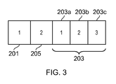
- Figure 2 is a schematic representation of radio resource allocation for MTCH1 and MTCH2 scheduled to be transmitted on the same subframe (i.e. TTI) according to an example.
- MCCH1 is signalled in a subframe 1 (201) and indicates that, for example, MTCH1, MTCH3, MTCH5 belong to an MCCH1. Additionally, MCCH1 indicates subframes1,2, and 3 (203) are used for the scheduling of MTCHs belonging to MCCH1.
- MCCH2 is signalled in subframe 2 (205) and indicates that MTCH2, MTCH4 and MTCH6, for exsample, belong to MCCH2. Further MCCH2 indicates that subframes 1,2 and 3 (203) are used for scheduling of MTChs belonging to MCCH2. In this example subframs 1,2 and 3 (203) are used to schedule MTCH1 - MTCH6. MTCH1 is mapped to LCID1, MTCH2 mapped to LCID2 and so on. LCID0 is used as the dummy Logical channel.
- Figure 3a is a schematic representation of signalling in respect of MSI MAC CE for the MTCHs belonging to MCCH1.
- Figure 3b is a schematic representation of signalling in respect of MSI MAC CE for the MTCHs belonging to MCCH2.
- the UE interested in MTCH1 stores the data received on subframe 1 (201).
- the UEs listening to the MTCHs of MCCH2 do not store the data on subframe 1 (201) as it is indicated for the dummy LCID. Therefore resource collision between the MTCH of MCCH1 and MCCH2 is avoided.
- This approach can be generalized to MCH resource sharing for scheduling of MTCHs from two or more MCCHs.
- MCCHs can be belong to the same MBSFN area or different MBSFN areas. This approach provides efficient use of radio resources.
- radio resource partitioned at subframe levels can be used for MTCHs scheduled from a first MCCH and a second MCCH.
- a possible realisation of MTCHs scheduled from a first MCCH and a second MCCH isdescribed below. It is assumed that MTCH1, MTCH2, and MTCH3 belong fo MCCH1 while MTCH4, MTCH5 and MTCH6 belong to MCCH2.
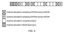
- the subframe allocated for transmission of the MTCH belonging to MCCH1 and MCCH2 do not overlap as shown in figure 4 , which is a schematic representation of radio resource allocation according to an example. Therefore, the resources used for MTCH1,MTCH2 and MTCH3 transmission do not collide with that of MTCH4, MTCH5 and MTCH6.
- the subframe level resource allocation for MTCHs belong to MCCH1 and MCCH2 has a limitation in terms of the efficiency of radio resource due to the fact that MTCHs from two MCCHs cannot be transmitted on the same subframe.
- this approach provides a simple configuration mechanism from a network point of view.
Landscapes
- Engineering & Computer Science (AREA)
- Computer Networks & Wireless Communication (AREA)
- Signal Processing (AREA)
- Multimedia (AREA)
- Mobile Radio Communication Systems (AREA)
Abstract
Description
- The present invention relates to wireless communications, and more particularly although not exclusively, to transmission and reception of messages relating to a multimedia broadcast/multicast service (MBMS).
- In a wireless telecommunications system, services for broadcast or multicast of messages and data to user equipment (UE) can be provided. Such services, referred to as multimedia broadcast multicast services (MBMS), can be transmitted throughout a single cell or throughout several contiguous or overlapping cells of the system, with a set of cells receiving an MBMS referred to as a service area.
- Typically, transmission for an MBMS occurs over two channels: a multicast control channel (MCCH) and a multicast traffic channel (MTCH). The MTCH delivers content of the MBMS, and the MCCH delivers control information related to the MBMS. The MCCH might include key control information that specifies how the content in the MTCH is to be delivered for example, and MCCH channels are used as point-to-multipoint downlink channels to transmit MCCH information. In general, one cell has one corresponding MCCH.
- In the Long Term Evolution (LTE) architecture, an enhanced version of MBMS (eMBMS), referred to as Multicast-Broadcast Single-Frequency Network (MBSFN), supports broadcast only services. A plurality of MBSFN areas can be defined, each having an MCCH channel to transmit MCCH information to all UEs in the MBSFN area in question.
- MBMS information on the MCCH channel is transmitted according to a fixed schedule, which is common for all services. Thus, the majority of MCCH information is transmitted periodically based on a repetition period. This MCCH information is repeated a configurable number of times with exactly the same content. The time period in which the content of this MCCH information remains unchanged is called the 'modification period'.
- According to an example, there is provided a method, performed in a wireless telecommunication system providing communication services to multiple user equipment (UE) devices across multiple cells of the system and supporting broadcast information services in one or more multimedia-broadcast multicast-service single frequency network (MBSFN) areas of the system, comprising providing a first point-to-multipoint multicast control channel (MCCH) and at least one additional MCCH channel per MBSFN area. For an MBSFN area, a periodicity for the at least one additional MCCH can be selected that is different to the periodicity of the first MCCH of the MBSFN area. The modification period of the at least one additional MCCH in an MBSFN area can be configured to a lower value than the modification period of the first MCCH channel for the area. The at least one additional MCCH channel can be configured independently of the first MCCH channel for an area. Multiple multicast traffic channels (MTCHs) belonging to different MCCHs can be transmitted in the same physical multicast channel (PMCH) in a transmission time interval (TTI). Radio resource can be partitioned at the subframe level for the scheduling of MTCHs belonging to different MCCHs.
- According to an example, there is provided a method for supporting point-to-multipoint multicast communication with multiple UE devices in a wireless telecommunication system, the method comprising providing a first multicast control channel (MCCH) for use with the multiple UEs with a first modification period, providing a second MCCH for use with at least a subset of the multiple UEs. The second MCCH can have a second modification period that is smaller than the first modification period. The first MCCH can be an unmodified control channel for the system. The first MCCH can be used in connection with transmission of a first type of service, and the at least one additional MCCH is used in connection with transmission for a public safety service.
- According to an example, there is provided user equipment configured to monitor a first multicast control channel (MCCH) of a wireless telecommunications system periodically according to a first period, and to monitor a second MCCH of the system periodically according to a second period.
- According to an example, there is provided a wireless telecommunication system operable to provide communication services to multiple user equipment (UE) devices across multiple cells of the system and to support broadcast information services in one or more multimedia-broadcast multicast-service single frequency network (MBSFN) areas of the system, the system including a node operable to communicate with user equipment using a first point-to-multipoint multicast control channel (MCCH) and at least one additional MCCH channel per MBSFN area.
- According to an example, there is provided a node in a wireless telecommunication system operable to provide communication services to multiple user equipment (UE) devices across multiple cells of the system and to support broadcast information services in one or more multimedia-broadcast multicast-service single frequency network (MBSFN) areas of the system, the node operable to communicate with user equipment using a first point-to-multipoint multicast control channel (MCCH) and at least one additional MCCH channel per MBSFN area. The node can be operable to configure a periodicity for the at least one additional MCCH that is different to the periodicity of the first MCCH of the MBSFN area.
- According to an example, there is provided a computer program product, comprising a computer usable medium having computer readable program code embodied therein, said computer readable program code adapted to be executed to implement a method, in a wireless telecommunication system, as provided above.
- Embodiments will now be described, by way of example only, with reference to the accompanying drawings, in which:
-
Figure 1 is a schematic representation of a wireless telecommunication system according to an example; -
Figure 2 is a schematic representation of radio resource allocation according to an example; -
Figure 3a is a schematic representation of signalling according to an example; -
Figure 3b is a schematic representation of signalling according to an example; and -
Figure 4 is a schematic representation of radio resource allocation according to an example. - Example embodiments are described below in sufficient detail to enable those of ordinary skill in the art to embody and implement the systems and processes herein described. It is important to understand that embodiments can be provided in many alternate forms and should not be construed as limited to the examples set forth herein.
- Accordingly, while embodiments can be modified in various ways and take on various alternative forms, specific embodiments thereof are shown in the drawings and described in detail below as examples. There is no intent to limit to the particular forms disclosed. On the contrary, all modifications, equivalents, and alternatives falling within the scope of the appended claims should be included. Elements of the example embodiments are consistently denoted by the same reference numerals throughout the drawings and detailed description where appropriate.
- The terminology used herein to describe embodiments is not intended to limit the scope. The articles "a," "an," and "the" are singular in that they have a single referent, however the use of the singular form in the present document should not preclude the presence of more than one referent. In other words, elements referred to in the singular can number one or more, unless the context clearly indicates otherwise. It will be further understood that the terms "comprises," "comprising," "includes," and/or "including," when used herein, specify the presence of stated features, items, steps, operations, elements, and/or components, but do not preclude the presence or addition of one or more other features, items, steps, operations, elements, components, and/or groups thereof.
- Unless otherwise defined, all terms (including technical and scientific terms) used herein are to be interpreted as is customary in the art. It will be further understood that terms in common usage should also be interpreted as is customary in the relevant art and not in an idealized or overly formal sense unless expressly so defined herein.
-
Figure 1 is a schematic representation of awireless telecommunication system 100, which may be an LTE network or some other wireless network, according to an example.Wireless network 100 may include a number of evolved Node Bs (eNBs) 110 and other network entities. For simplicity, only three eNBs 110a, 110b and 110c and onenetwork controller 141 are shown infigure 1 . An eNB communicates with UEs 120. Each eNB 110 provides communication coverage for a particular geographic area (cell) 130 and supports communication for the UEs located within the coverage area of the cell. Whilesuch cells 130 are depicted as having non-overlapping coverage areas, persons of ordinary skill in the art will recognize that one or more of thecells 130 may have partially overlapping coverage with adjacent cells. - UEs 120 may be dispersed throughout the
system 100, and UEs can be stationary or mobile. A UE communicates with an eNB via the downlink and uplink. The downlink refers to the communication link from the eNB to the UE, and the uplink refers to the communication link from the UE to the eNB. Bi-directional communication between an eNB and a UE is depicted infigure 1 by a solid line with double arrows. -
Wireless network 100 may support MBMS services for multiple UEs as well as unicast services for individual UEs. An MBMS service may be a broadcast service or a multicast service. MBMS services may be supported with a multi-cell mode, a single-cell mode, and/or other modes. In the multi-cell mode, multiple cells may simultaneously send a MBMS transmission using multimedia broadcast single frequency network (MBSFN), which may allow a UE to combine the signals received from the multiple cells in order to improve reception performance for example. In the single-cell mode, a cell may send a MBSFN transmission by itself. - In LTE for example, data and overhead information are processed as logical channels at a Radio Link Control (RLC) layer. The logical channels are mapped to transport channels at a Medium Access Control (MAC) layer. The transport channels are mapped to physical channels at a physical layer (PHY). A broadcast control channel (BCCH) can carry system information blocks (SIBs), with each SIB including certain system information pertinent for communicating with and/or receiving data from a cell. The MCCH may carry control information used to receive MBMS services, such as a list of MBMS services with ongoing sessions, information used to receive the MTCH, and so on. The MTCH may carry data for MBMS services.
- From a public safety perspective, group communication in a
radio telecommunications system 100 is an important consideration. The enhanced MBMS (eMBMS) procedure can provide a suitable approach for the support of group communication from radio resource efficiency perspectives, since group communication typically requires the transmission of the same information to a large number of receiving group members. Particularly from a public safety point of view, group communication has certain latency requirements that may need to be satisfied in order to make it viable. One such requirement is on the end-to-end setup delay. Typically, this should satisfy 300ms. However an eMBMS procedure uses the multicast control channel (MCCH) to inform the bearer configuration of new media. The MCCH can only be modified at an MCCH modification boundary, which is set to 5.12s or 10.2 sec. A 5-10s delay cannot be tolerable in respect of group communication in emergency public safety communications scenarios. - According to an example, in order to avoid any impacts on legacy UEs who are using eMBMS for other applications, such as mobile TV for example, multiple MCCHs can be provided, with at least one of the multiple channels being defined with a relatively small MCCH modification period for use in group communication for applications such as public safety. For example, the modification period can be defined to be as small as 10ms.
- Multicast-broadcast single-frequency network (MBSFN) is a transmission mode which exploits LTE's OFDM radio interface to send multicast or broadcast data as a multi-cell transmission over a synchronized single-frequency network (SFN). An MBSFN transmission appears to a
UE 120 as a transmission from a single large cell. Typically, only one MCCH can be configured per MBSFN area. According to an example however, more than one MCCH is configured for an MBSFN area. - The first MCCH configuration is unmodified from the legacy system. Second, third and so on MCCHs are configured independently from the first MCCH. Also the configuration is performed such that the physical resources associated with first and second MCCH do not collide. Additionally, an MCCH change notification is used unmodified for the first MCCH change. The second, third and so on MCCHs are not considered within the MCCH change notification. A UE supporting group communication for public safety monitors the MCCH in a periodic manner to acquire the MCCH changes.
- MCCH is defined per MBSFN area and a maximum of 8 MBSFN areas can be supported in a cell of a telecommunications system. System Information Blocks (SIBs) comprise system information data that is transmitted to a UE from the access network of a system. The information element SIB13 provides the information required for decoding of the MCCH and for acquiring the MBMS control information associated with one or more MBSFN areas, and is structured as follows:

- "MBSFN-AreaInfoList" carries the information on MCCH configuration per MBSFN area, and thus contains the information required to acquire the MBMS control information associated with one or more MBSFN areas. A typical signalling format is as follows:

- According to an example, multiple MCCHs are provided per MBSFN area. The second, third and so on MCCH configurations can be signalled in MBSFN-AreaInfoList IE following the legacy signalling structure. The modification (bold) to introduce a second MCCH is as follows:


- According to an example, the following configuration options can be realized:
- Configure a relatively small MCCH periodicity, and in this case no repetition is used for the MCCH transmission
- Configure MCCH periodicity and MCCH repetition for the MCCH transmission
- MCCH periodicity can take any value from 1-10ms to 10.12s depending on the application
- Second (or further) MCCH is configured independently from first MCCH configuration
- MCCH change notification is not provided for the second, third, ... MCCHs
- The first MCCH can be used in connection with transmission of a first type of service, such as a TV service for example. An additional MCCH can be used in connection with transmission for another service, such as a public safety service for example. Typically, MCCH can only be modified at the MCCH modification boundary, which is currently set to 5.12s or 10.2 sec. These values are not tolerable for group communication in emergency public safety communications. Therefore, to avoid the delay from MCCH modification for public safety but at the same time avoid any impacts on legacy UEs that may be using eMBMS for other applications, such as mobile TV for example, at least one additional MCCH is provided with a modification period that is defined to have a value that is lower than the legacy case, such as a value within the range 1ms to 5.12s or 10.2s for example.
- In terms of informing the MCCH changes to the UE for the second, third, and so on MCCH that has been configured with a relatively small (compared to the legacy MCCH) periodicity, the UE procedure is modified such that the UE is required to monitor MCCH at the MCCH modification boundary in an example.
- If an MCCH change notification is seen essential requirement for second, third MCCHs for example to achieve the UE power saving, a new MCCH change notification, which is independent of first MCCH is required.
- In order to reduce the amount of signalling bits required for transmission of an additional MCCH configuration, a delta information transmission compared to the first MCCH configuration can be provided. That is, only parameter values which are different from the first (legacy) MCCH are transmitted for any additional MCCH. Thus a UE decoding both first and the second (or further) MCCH configuration data can realise the full configuration for the second (and so on) MCCH.
- If the physical resources used for transmission on MTCHs collide, the radio waveform will be corrupted and any receiving UEs will therefore not be able to receive data correctly. This is therefore a waste of radio resources.
- According to an example, the avoidance of physical resource collision can be avoided in two ways. Note that the radio resource for MTCH transmission is scheduled via the MCH scheduling information MAC CE, which is a MAC command transmitted at the beginning of the MCH scheduling period. The physical resource scheduled for a particular MTCH is informed with the indication of the start subframe and end subframe.
Figure 1 is a schematic representation of the format used for MCH scheduling information MAC control element. - LCID is the logical channel ID of the MTCH. The length of the field is 5 bits. In the example of
figure 1 , multiple LCIDs are depicted (LCID1 (101), LCID2 (103)...LCIDn (105)). The stop MTCH field (107, 109, 111) indicates the ordinal number of the subframe within the MCH scheduling period, counting only the subframes allocated to the MCH, where the corresponding MTCH stops.Value 0 corresponds to the first subframe. The length of the field is 11 bits. The special Stop MTCH value 2047 indicates that the corresponding MTCH is not scheduled. The value range 2043 to 2046 is reserved. - In an example, radio resource collision can be avoided via scheduling within a subframe. More specifically, the resources that are to be used for particular MTCH are coordinated among eNBs involved in the eMBMS transmission. The data scheduled via two or more MCCHs are taken into account in the resource coordination in such a way to avoid any resource collision. This approach provides a finer granularity of resource allocation while avoiding resource collision. For example MTCH1 scheduled from MCCH1, and MTCH2 scheduled from MCCH2 can be transmitted in the same physical multicast channel (PMCH) in a transmission time interval (TTI). In order to inform the UEs who are only interested in receiving MTCHs scheduled from MCCH1 for example, a dummy logical channel ID (from the received logical channel ID space) can be used to inform the UEs in question to free up of resources for the use of other MTCHs. Legacy UEs can ignore the use of dummy logical channel IDs.
-
Figure 2 is a schematic representation of radio resource allocation for MTCH1 and MTCH2 scheduled to be transmitted on the same subframe (i.e. TTI) according to an example. - MCCH1 is signalled in a subframe 1 (201) and indicates that, for example, MTCH1, MTCH3, MTCH5 belong to an MCCH1. Additionally, MCCH1 indicates subframes1,2, and 3 (203) are used for the scheduling of MTCHs belonging to MCCH1.
- MCCH2 is signalled in subframe 2 (205) and indicates that MTCH2, MTCH4 and MTCH6, for exsample, belong to MCCH2. Further MCCH2 indicates that
subframes example subframs -
Figure 3a is a schematic representation of signalling in respect of MSI MAC CE for the MTCHs belonging to MCCH1. -
Figure 3b is a schematic representation of signalling in respect of MSI MAC CE for the MTCHs belonging to MCCH2. - In the example, the UE interested in MTCH1 stores the data received on subframe 1 (201). The UEs listening to the MTCHs of MCCH2 do not store the data on subframe 1 (201) as it is indicated for the dummy LCID. Therefore resource collision between the MTCH of MCCH1 and MCCH2 is avoided.
- This approach can be generalized to MCH resource sharing for scheduling of MTCHs from two or more MCCHs. MCCHs can be belong to the same MBSFN area or different MBSFN areas. This approach provides efficient use of radio resources.
- In an example, radio resource partitioned at subframe levels can be used for MTCHs scheduled from a first MCCH and a second MCCH. A possible realisation of MTCHs scheduled from a first MCCH and a second MCCH isdescribed below. It is assumed that MTCH1, MTCH2, and MTCH3 belong fo MCCH1 while MTCH4, MTCH5 and MTCH6 belong to MCCH2. The subframe allocated for transmission of the MTCH belonging to MCCH1 and MCCH2 do not overlap as shown in
figure 4 , which is a schematic representation of radio resource allocation according to an example. Therefore, the resources used for MTCH1,MTCH2 and MTCH3 transmission do not collide with that of MTCH4, MTCH5 and MTCH6. - However, the subframe level resource allocation for MTCHs belong to MCCH1 and MCCH2 has a limitation in terms of the efficiency of radio resource due to the fact that MTCHs from two MCCHs cannot be transmitted on the same subframe. However, this approach provides a simple configuration mechanism from a network point of view.
- The present inventions can be embodied in other specific apparatus and/or methods. The described embodiments are to be considered in all respects as illustrative and not restrictive. In particular, the scope of the invention is indicated by the appended claims rather than by the description and figures herein. All changes that come within the meaning and range of equivalency of the claims are to be embraced within their scope.
Claims (15)
- A method, performed in a wireless telecommunication system providing communication services to multiple user equipment (UE) devices across multiple cells of the system and supporting broadcast information services in one or more multimedia-broadcast multicast-service single frequency network (MBSFN) areas of the system, comprising providing a first point-to-multipoint multicast control channel (MCCH) and at least one additional MCCH channel per MBSFN area.
- A method a claimed in claim 1, further comprising, for an MBSFN area, selecting a periodicity for the at least one additional MCCH that is different to the periodicity of the first MCCH of the MBSFN area.
- A method a claimed in claim 1 or 2, further comprising configuring the modification period of the at least one additional MCCH in an MBSFN area to a lower value than the modification period of the first MCCH channel for the area.
- A method as claimed in claim 2 or 3, wherein the at least one additional MCCH channel is configured independently of the first MCCH channel for an area.
- A method as claimed in any preceding claim, further comprising transmitting multiple multicast traffic channels (MTCHs) belonging to different MCCHs in the same physical multicast channel (PMCH) in a transmission time interval (TTI).
- A method as claimed in any of claims 1 to 4, further comprising partitioning radio resource at the subframe level for the scheduling of MTCHs belonging to different MCCHs.
- A method for supporting point-to-multipoint multicast communication with multiple UE devices in a wireless telecommunication system, the method comprising:providing a first multicast control channel (MCCH) for use with the multiple UEs with a first modification period;providing a second MCCH for use with at least a subset of the multiple UEs.
- A method as claimed in claim 7, wherein the second MCCH has a second modification period that is smaller than the first modification period.
- A method as claimed in any preceding claim, wherein the first MCCH is an unmodified control channel for the system.
- A method as claimed in any preceding claim, wherein the first MCCH is used in connection with transmission of a first type of service, and the at least one additional MCCH is used in connection with transmission for a public safety service.
- User equipment configured to monitor a first multicast control channel (MCCH) of a wireless telecommunications system periodically according to a first period, and to monitor a second MCCH of the system periodically according to a second period.
- A wireless telecommunication system operable to provide communication services to multiple user equipment (UE) devices across multiple cells of the system and to support broadcast information services in one or more multimedia-broadcast multicast-service single frequency network (MBSFN) areas of the system, the system including a node operable to communicate with user equipment using a first point-to-multipoint multicast control channel (MCCH) and at least one additional MCCH channel per MBSFN area.
- A node in a wireless telecommunication system operable to provide communication services to multiple user equipment (UE) devices across multiple cells of the system and to support broadcast information services in one or more multimedia-broadcast multicast-service single frequency network (MBSFN) areas of the system, the node operable to communicate with user equipment using a first point-to-multipoint multicast control channel (MCCH) and at least one additional MCCH channel per MBSFN area.
- A node as claimed in claim 13, further operable to configure a periodicity for the at least one additional MCCH that is different to the periodicity of the first MCCH of the MBSFN area.
- A computer program product, comprising a computer usable medium having computer readable program code embodied therein, said computer readable program code adapted to be executed to implement a method, in a wireless telecommunication system, as claimed in any of claims 1 to 10.
Priority Applications (6)
| Application Number | Priority Date | Filing Date | Title |
|---|---|---|---|
| EP13290267.7A EP2869607B1 (en) | 2013-11-01 | 2013-11-01 | Wireless communication system, method, user equipment, node and computer program product |
| JP2016527188A JP6335291B2 (en) | 2013-11-01 | 2014-10-24 | Wireless communication system, method, user equipment, node, and computer program product |
| PCT/EP2014/002871 WO2015062712A1 (en) | 2013-11-01 | 2014-10-24 | Wireless communication system, method, user equipment, node and computer program product |
| US15/033,243 US10111203B2 (en) | 2013-11-01 | 2014-10-24 | Wireless communication system, method, user equipment, node and computer program product |
| CN201480058957.XA CN105684472B (en) | 2013-11-01 | 2014-10-24 | System for wireless communication, method, user equipment, node and medium |
| TW103138046A TWI573479B (en) | 2013-11-01 | 2014-11-03 | Wireless communication system, method, user equipment, node and computer program product |
Applications Claiming Priority (1)
| Application Number | Priority Date | Filing Date | Title |
|---|---|---|---|
| EP13290267.7A EP2869607B1 (en) | 2013-11-01 | 2013-11-01 | Wireless communication system, method, user equipment, node and computer program product |
Publications (2)
| Publication Number | Publication Date |
|---|---|
| EP2869607A1 true EP2869607A1 (en) | 2015-05-06 |
| EP2869607B1 EP2869607B1 (en) | 2019-12-25 |
Family
ID=49639814
Family Applications (1)
| Application Number | Title | Priority Date | Filing Date |
|---|---|---|---|
| EP13290267.7A Active EP2869607B1 (en) | 2013-11-01 | 2013-11-01 | Wireless communication system, method, user equipment, node and computer program product |
Country Status (6)
| Country | Link |
|---|---|
| US (1) | US10111203B2 (en) |
| EP (1) | EP2869607B1 (en) |
| JP (1) | JP6335291B2 (en) |
| CN (1) | CN105684472B (en) |
| TW (1) | TWI573479B (en) |
| WO (1) | WO2015062712A1 (en) |
Families Citing this family (2)
| Publication number | Priority date | Publication date | Assignee | Title |
|---|---|---|---|---|
| US10542409B2 (en) * | 2016-10-07 | 2020-01-21 | Qualcomm Incorporated | Access for group call services through a broadcast channel |
| US11564065B2 (en) * | 2020-02-13 | 2023-01-24 | Qualcomm Incorporated | Multimedia broadcast multicast service signaling and backward compatibility |
Citations (1)
| Publication number | Priority date | Publication date | Assignee | Title |
|---|---|---|---|---|
| EP2512160A1 (en) * | 2010-02-11 | 2012-10-17 | ZTE Corporation | Receiving method, receiving equipment and user equipment for multicast control channels (mcchs) information |
Family Cites Families (4)
| Publication number | Priority date | Publication date | Assignee | Title |
|---|---|---|---|---|
| CN102176771B (en) | 2007-07-05 | 2015-01-07 | 三菱电机株式会社 | Mobile communication system, base station and mobile terminal |
| CN103401668B (en) * | 2007-12-17 | 2016-12-28 | Tcl通讯科技控股有限公司 | Mobile communication system |
| CN101552950B (en) * | 2008-04-01 | 2011-04-20 | 大唐移动通信设备有限公司 | Method and device for transmitting multimedia broadcast service control data |
| CN102118693B (en) | 2009-12-31 | 2015-06-24 | 中兴通讯股份有限公司 | Method and device for sensing multicast control channel (MCCH) updating indication information |
-
2013
- 2013-11-01 EP EP13290267.7A patent/EP2869607B1/en active Active
-
2014
- 2014-10-24 US US15/033,243 patent/US10111203B2/en active Active
- 2014-10-24 JP JP2016527188A patent/JP6335291B2/en active Active
- 2014-10-24 WO PCT/EP2014/002871 patent/WO2015062712A1/en not_active Ceased
- 2014-10-24 CN CN201480058957.XA patent/CN105684472B/en active Active
- 2014-11-03 TW TW103138046A patent/TWI573479B/en active
Patent Citations (1)
| Publication number | Priority date | Publication date | Assignee | Title |
|---|---|---|---|---|
| EP2512160A1 (en) * | 2010-02-11 | 2012-10-17 | ZTE Corporation | Receiving method, receiving equipment and user equipment for multicast control channels (mcchs) information |
Non-Patent Citations (1)
| Title |
|---|
| "E-mail discussion on multiple MBSFN support (67#31)", 3GPP DRAFT; R2-095906 REPORT OF EMAIL DISCUSSION ON MBMS MULTIPLE MBSFN SUPPORT 67#31_FINAL, 3RD GENERATION PARTNERSHIP PROJECT (3GPP), MOBILE COMPETENCE CENTRE ; 650, ROUTE DES LUCIOLES ; F-06921 SOPHIA-ANTIPOLIS CEDEX ; FRANCE, vol. RAN WG2, no. Miyazaki; 20091012 - 20091016, 5 October 2009 (2009-10-05), XP050604723 * |
Also Published As
| Publication number | Publication date |
|---|---|
| JP2016535502A (en) | 2016-11-10 |
| CN105684472B (en) | 2019-01-11 |
| JP6335291B2 (en) | 2018-05-30 |
| US10111203B2 (en) | 2018-10-23 |
| EP2869607B1 (en) | 2019-12-25 |
| WO2015062712A1 (en) | 2015-05-07 |
| TWI573479B (en) | 2017-03-01 |
| US20160249325A1 (en) | 2016-08-25 |
| TW201532460A (en) | 2015-08-16 |
| CN105684472A (en) | 2016-06-15 |
Similar Documents
| Publication | Publication Date | Title |
|---|---|---|
| EP2134103B1 (en) | Scheduling method directed to mbms, scheduling device and base station including scheduling device | |
| KR101125660B1 (en) | Method for realizing mbms tdm and the information transmission method thereof | |
| KR101365580B1 (en) | Arrangement method, facility and system of MBMS control information | |
| CN102638767B (en) | A kind of group service transmission method and device | |
| EP2254387B1 (en) | Indication method of a single frequency network mbms frame | |
| EP2416536B1 (en) | Transmission method and system for multimedia broadcast multicast service control signaling | |
| EP2706764B1 (en) | Method and device for synchronously counting mbms service | |
| EP2446687A2 (en) | Appratus and method for signalling sub-frame allocation pattern | |
| CN105635985B (en) | Method and device for determining suspended service and method and device for processing indication information | |
| KR20170069023A (en) | Method and apparatus for operation of resource in a wireless communication system | |
| CN101873527B (en) | Method and device for allocating and delivering MCH (Multi-cast Channel) physical resource | |
| CN102264031B (en) | Method and system for distributing radio resources for multicast control channel | |
| CN101841772A (en) | Transmission method, system and device of MBMS | |
| CN101640843B (en) | Method for transmitting multimedia broadcast and multicast service resource configuration information | |
| CN101500189A (en) | Method, system and terminal for implementing information scheduling | |
| CN105264852A (en) | Service processing method, device and communication system of new carrier type cell | |
| EP2869607B1 (en) | Wireless communication system, method, user equipment, node and computer program product | |
| CN101841769B (en) | Transmission method, system and device of MBMS | |
| CN106559808B (en) | Media access control layer processing method and device | |
| US12464321B2 (en) | Method for dynamic MBMS control, user equipment and telecommunication system | |
| CN101877823A (en) | A scheduling method and device for multicast broadcast service | |
| CN102026095A (en) | Transmission method, system and device of MBMS Notification | |
| HK1163972B (en) | Transmission method and system for multimedia broadcast multicast service control signaling | |
| HK1150001B (en) | Indication method of a single frequency network mbms frame |
Legal Events
| Date | Code | Title | Description |
|---|---|---|---|
| PUAI | Public reference made under article 153(3) epc to a published international application that has entered the european phase |
Free format text: ORIGINAL CODE: 0009012 |
|
| 17P | Request for examination filed |
Effective date: 20131101 |
|
| AK | Designated contracting states |
Kind code of ref document: A1 Designated state(s): AL AT BE BG CH CY CZ DE DK EE ES FI FR GB GR HR HU IE IS IT LI LT LU LV MC MK MT NL NO PL PT RO RS SE SI SK SM TR |
|
| AX | Request for extension of the european patent |
Extension state: BA ME |
|
| R17P | Request for examination filed (corrected) |
Effective date: 20151106 |
|
| RBV | Designated contracting states (corrected) |
Designated state(s): AL AT BE BG CH CY CZ DE DK EE ES FI FR GB GR HR HU IE IS IT LI LT LU LV MC MK MT NL NO PL PT RO RS SE SI SK SM TR |
|
| RAP1 | Party data changed (applicant data changed or rights of an application transferred) |
Owner name: ALCATEL LUCENT |
|
| REG | Reference to a national code |
Ref country code: DE Ref legal event code: R079 Ref document number: 602013064305 Country of ref document: DE Free format text: PREVIOUS MAIN CLASS: H04W0004060000 Ipc: H04W0072000000 |
|
| RIC1 | Information provided on ipc code assigned before grant |
Ipc: H04W 72/00 20090101AFI20190507BHEP Ipc: H04W 4/06 20090101ALI20190507BHEP |
|
| GRAP | Despatch of communication of intention to grant a patent |
Free format text: ORIGINAL CODE: EPIDOSNIGR1 |
|
| STAA | Information on the status of an ep patent application or granted ep patent |
Free format text: STATUS: GRANT OF PATENT IS INTENDED |
|
| INTG | Intention to grant announced |
Effective date: 20190701 |
|
| GRAS | Grant fee paid |
Free format text: ORIGINAL CODE: EPIDOSNIGR3 |
|
| GRAA | (expected) grant |
Free format text: ORIGINAL CODE: 0009210 |
|
| STAA | Information on the status of an ep patent application or granted ep patent |
Free format text: STATUS: THE PATENT HAS BEEN GRANTED |
|
| AK | Designated contracting states |
Kind code of ref document: B1 Designated state(s): AL AT BE BG CH CY CZ DE DK EE ES FI FR GB GR HR HU IE IS IT LI LT LU LV MC MK MT NL NO PL PT RO RS SE SI SK SM TR |
|
| REG | Reference to a national code |
Ref country code: GB Ref legal event code: FG4D |
|
| REG | Reference to a national code |
Ref country code: CH Ref legal event code: EP |
|
| REG | Reference to a national code |
Ref country code: AT Ref legal event code: REF Ref document number: 1218556 Country of ref document: AT Kind code of ref document: T Effective date: 20200115 |
|
| REG | Reference to a national code |
Ref country code: DE Ref legal event code: R096 Ref document number: 602013064305 Country of ref document: DE |
|
| REG | Reference to a national code |
Ref country code: IE Ref legal event code: FG4D |
|
| REG | Reference to a national code |
Ref country code: NL Ref legal event code: MP Effective date: 20191225 |
|
| PG25 | Lapsed in a contracting state [announced via postgrant information from national office to epo] |
Ref country code: SE Free format text: LAPSE BECAUSE OF FAILURE TO SUBMIT A TRANSLATION OF THE DESCRIPTION OR TO PAY THE FEE WITHIN THE PRESCRIBED TIME-LIMIT Effective date: 20191225 Ref country code: LV Free format text: LAPSE BECAUSE OF FAILURE TO SUBMIT A TRANSLATION OF THE DESCRIPTION OR TO PAY THE FEE WITHIN THE PRESCRIBED TIME-LIMIT Effective date: 20191225 Ref country code: FI Free format text: LAPSE BECAUSE OF FAILURE TO SUBMIT A TRANSLATION OF THE DESCRIPTION OR TO PAY THE FEE WITHIN THE PRESCRIBED TIME-LIMIT Effective date: 20191225 Ref country code: BG Free format text: LAPSE BECAUSE OF FAILURE TO SUBMIT A TRANSLATION OF THE DESCRIPTION OR TO PAY THE FEE WITHIN THE PRESCRIBED TIME-LIMIT Effective date: 20200325 Ref country code: NO Free format text: LAPSE BECAUSE OF FAILURE TO SUBMIT A TRANSLATION OF THE DESCRIPTION OR TO PAY THE FEE WITHIN THE PRESCRIBED TIME-LIMIT Effective date: 20200325 Ref country code: LT Free format text: LAPSE BECAUSE OF FAILURE TO SUBMIT A TRANSLATION OF THE DESCRIPTION OR TO PAY THE FEE WITHIN THE PRESCRIBED TIME-LIMIT Effective date: 20191225 Ref country code: GR Free format text: LAPSE BECAUSE OF FAILURE TO SUBMIT A TRANSLATION OF THE DESCRIPTION OR TO PAY THE FEE WITHIN THE PRESCRIBED TIME-LIMIT Effective date: 20200326 |
|
| REG | Reference to a national code |
Ref country code: LT Ref legal event code: MG4D |
|
| PG25 | Lapsed in a contracting state [announced via postgrant information from national office to epo] |
Ref country code: RS Free format text: LAPSE BECAUSE OF FAILURE TO SUBMIT A TRANSLATION OF THE DESCRIPTION OR TO PAY THE FEE WITHIN THE PRESCRIBED TIME-LIMIT Effective date: 20191225 Ref country code: HR Free format text: LAPSE BECAUSE OF FAILURE TO SUBMIT A TRANSLATION OF THE DESCRIPTION OR TO PAY THE FEE WITHIN THE PRESCRIBED TIME-LIMIT Effective date: 20191225 |
|
| PG25 | Lapsed in a contracting state [announced via postgrant information from national office to epo] |
Ref country code: AL Free format text: LAPSE BECAUSE OF FAILURE TO SUBMIT A TRANSLATION OF THE DESCRIPTION OR TO PAY THE FEE WITHIN THE PRESCRIBED TIME-LIMIT Effective date: 20191225 |
|
| PG25 | Lapsed in a contracting state [announced via postgrant information from national office to epo] |
Ref country code: PT Free format text: LAPSE BECAUSE OF FAILURE TO SUBMIT A TRANSLATION OF THE DESCRIPTION OR TO PAY THE FEE WITHIN THE PRESCRIBED TIME-LIMIT Effective date: 20200520 Ref country code: EE Free format text: LAPSE BECAUSE OF FAILURE TO SUBMIT A TRANSLATION OF THE DESCRIPTION OR TO PAY THE FEE WITHIN THE PRESCRIBED TIME-LIMIT Effective date: 20191225 Ref country code: NL Free format text: LAPSE BECAUSE OF FAILURE TO SUBMIT A TRANSLATION OF THE DESCRIPTION OR TO PAY THE FEE WITHIN THE PRESCRIBED TIME-LIMIT Effective date: 20191225 Ref country code: RO Free format text: LAPSE BECAUSE OF FAILURE TO SUBMIT A TRANSLATION OF THE DESCRIPTION OR TO PAY THE FEE WITHIN THE PRESCRIBED TIME-LIMIT Effective date: 20191225 Ref country code: CZ Free format text: LAPSE BECAUSE OF FAILURE TO SUBMIT A TRANSLATION OF THE DESCRIPTION OR TO PAY THE FEE WITHIN THE PRESCRIBED TIME-LIMIT Effective date: 20191225 |
|
| PG25 | Lapsed in a contracting state [announced via postgrant information from national office to epo] |
Ref country code: SK Free format text: LAPSE BECAUSE OF FAILURE TO SUBMIT A TRANSLATION OF THE DESCRIPTION OR TO PAY THE FEE WITHIN THE PRESCRIBED TIME-LIMIT Effective date: 20191225 Ref country code: IS Free format text: LAPSE BECAUSE OF FAILURE TO SUBMIT A TRANSLATION OF THE DESCRIPTION OR TO PAY THE FEE WITHIN THE PRESCRIBED TIME-LIMIT Effective date: 20200425 Ref country code: SM Free format text: LAPSE BECAUSE OF FAILURE TO SUBMIT A TRANSLATION OF THE DESCRIPTION OR TO PAY THE FEE WITHIN THE PRESCRIBED TIME-LIMIT Effective date: 20191225 |
|
| REG | Reference to a national code |
Ref country code: DE Ref legal event code: R097 Ref document number: 602013064305 Country of ref document: DE |
|
| PG25 | Lapsed in a contracting state [announced via postgrant information from national office to epo] |
Ref country code: ES Free format text: LAPSE BECAUSE OF FAILURE TO SUBMIT A TRANSLATION OF THE DESCRIPTION OR TO PAY THE FEE WITHIN THE PRESCRIBED TIME-LIMIT Effective date: 20191225 Ref country code: DK Free format text: LAPSE BECAUSE OF FAILURE TO SUBMIT A TRANSLATION OF THE DESCRIPTION OR TO PAY THE FEE WITHIN THE PRESCRIBED TIME-LIMIT Effective date: 20191225 |
|
| PLBE | No opposition filed within time limit |
Free format text: ORIGINAL CODE: 0009261 |
|
| STAA | Information on the status of an ep patent application or granted ep patent |
Free format text: STATUS: NO OPPOSITION FILED WITHIN TIME LIMIT |
|
| REG | Reference to a national code |
Ref country code: AT Ref legal event code: MK05 Ref document number: 1218556 Country of ref document: AT Kind code of ref document: T Effective date: 20191225 |
|
| PG25 | Lapsed in a contracting state [announced via postgrant information from national office to epo] |
Ref country code: SI Free format text: LAPSE BECAUSE OF FAILURE TO SUBMIT A TRANSLATION OF THE DESCRIPTION OR TO PAY THE FEE WITHIN THE PRESCRIBED TIME-LIMIT Effective date: 20191225 |
|
| 26N | No opposition filed |
Effective date: 20200928 |
|
| PG25 | Lapsed in a contracting state [announced via postgrant information from national office to epo] |
Ref country code: AT Free format text: LAPSE BECAUSE OF FAILURE TO SUBMIT A TRANSLATION OF THE DESCRIPTION OR TO PAY THE FEE WITHIN THE PRESCRIBED TIME-LIMIT Effective date: 20191225 Ref country code: IT Free format text: LAPSE BECAUSE OF FAILURE TO SUBMIT A TRANSLATION OF THE DESCRIPTION OR TO PAY THE FEE WITHIN THE PRESCRIBED TIME-LIMIT Effective date: 20191225 |
|
| PG25 | Lapsed in a contracting state [announced via postgrant information from national office to epo] |
Ref country code: PL Free format text: LAPSE BECAUSE OF FAILURE TO SUBMIT A TRANSLATION OF THE DESCRIPTION OR TO PAY THE FEE WITHIN THE PRESCRIBED TIME-LIMIT Effective date: 20191225 |
|
| PG25 | Lapsed in a contracting state [announced via postgrant information from national office to epo] |
Ref country code: MC Free format text: LAPSE BECAUSE OF FAILURE TO SUBMIT A TRANSLATION OF THE DESCRIPTION OR TO PAY THE FEE WITHIN THE PRESCRIBED TIME-LIMIT Effective date: 20191225 |
|
| REG | Reference to a national code |
Ref country code: CH Ref legal event code: PL |
|
| PG25 | Lapsed in a contracting state [announced via postgrant information from national office to epo] |
Ref country code: LU Free format text: LAPSE BECAUSE OF NON-PAYMENT OF DUE FEES Effective date: 20201101 |
|
| REG | Reference to a national code |
Ref country code: BE Ref legal event code: MM Effective date: 20201130 |
|
| PG25 | Lapsed in a contracting state [announced via postgrant information from national office to epo] |
Ref country code: LI Free format text: LAPSE BECAUSE OF NON-PAYMENT OF DUE FEES Effective date: 20201130 Ref country code: CH Free format text: LAPSE BECAUSE OF NON-PAYMENT OF DUE FEES Effective date: 20201130 |
|
| PG25 | Lapsed in a contracting state [announced via postgrant information from national office to epo] |
Ref country code: IE Free format text: LAPSE BECAUSE OF NON-PAYMENT OF DUE FEES Effective date: 20201101 |
|
| PG25 | Lapsed in a contracting state [announced via postgrant information from national office to epo] |
Ref country code: TR Free format text: LAPSE BECAUSE OF FAILURE TO SUBMIT A TRANSLATION OF THE DESCRIPTION OR TO PAY THE FEE WITHIN THE PRESCRIBED TIME-LIMIT Effective date: 20191225 Ref country code: MT Free format text: LAPSE BECAUSE OF FAILURE TO SUBMIT A TRANSLATION OF THE DESCRIPTION OR TO PAY THE FEE WITHIN THE PRESCRIBED TIME-LIMIT Effective date: 20191225 Ref country code: CY Free format text: LAPSE BECAUSE OF FAILURE TO SUBMIT A TRANSLATION OF THE DESCRIPTION OR TO PAY THE FEE WITHIN THE PRESCRIBED TIME-LIMIT Effective date: 20191225 |
|
| PG25 | Lapsed in a contracting state [announced via postgrant information from national office to epo] |
Ref country code: MK Free format text: LAPSE BECAUSE OF FAILURE TO SUBMIT A TRANSLATION OF THE DESCRIPTION OR TO PAY THE FEE WITHIN THE PRESCRIBED TIME-LIMIT Effective date: 20191225 |
|
| PG25 | Lapsed in a contracting state [announced via postgrant information from national office to epo] |
Ref country code: BE Free format text: LAPSE BECAUSE OF NON-PAYMENT OF DUE FEES Effective date: 20201130 |
|
| PGFP | Annual fee paid to national office [announced via postgrant information from national office to epo] |
Ref country code: FR Payment date: 20250930 Year of fee payment: 13 |
|
| PGFP | Annual fee paid to national office [announced via postgrant information from national office to epo] |
Ref country code: DE Payment date: 20250930 Year of fee payment: 13 |
|
| PGFP | Annual fee paid to national office [announced via postgrant information from national office to epo] |
Ref country code: GB Payment date: 20251001 Year of fee payment: 13 |