EP2869529A1 - Systems and methods for secure file transfers - Google Patents
Systems and methods for secure file transfers Download PDFInfo
- Publication number
- EP2869529A1 EP2869529A1 EP20140191515 EP14191515A EP2869529A1 EP 2869529 A1 EP2869529 A1 EP 2869529A1 EP 20140191515 EP20140191515 EP 20140191515 EP 14191515 A EP14191515 A EP 14191515A EP 2869529 A1 EP2869529 A1 EP 2869529A1
- Authority
- EP
- European Patent Office
- Prior art keywords
- onsite
- data
- datagrams
- outbound
- computer program
- Prior art date
- Legal status (The legal status is an assumption and is not a legal conclusion. Google has not performed a legal analysis and makes no representation as to the accuracy of the status listed.)
- Granted
Links
Images



Classifications
-
- H—ELECTRICITY
- H04—ELECTRIC COMMUNICATION TECHNIQUE
- H04L—TRANSMISSION OF DIGITAL INFORMATION, e.g. TELEGRAPHIC COMMUNICATION
- H04L63/00—Network architectures or network communication protocols for network security
- H04L63/02—Network architectures or network communication protocols for network security for separating internal from external traffic, e.g. firewalls
-
- H—ELECTRICITY
- H04—ELECTRIC COMMUNICATION TECHNIQUE
- H04L—TRANSMISSION OF DIGITAL INFORMATION, e.g. TELEGRAPHIC COMMUNICATION
- H04L63/00—Network architectures or network communication protocols for network security
- H04L63/04—Network architectures or network communication protocols for network security for providing a confidential data exchange among entities communicating through data packet networks
- H04L63/0428—Network architectures or network communication protocols for network security for providing a confidential data exchange among entities communicating through data packet networks wherein the data content is protected, e.g. by encrypting or encapsulating the payload
-
- H—ELECTRICITY
- H04—ELECTRIC COMMUNICATION TECHNIQUE
- H04L—TRANSMISSION OF DIGITAL INFORMATION, e.g. TELEGRAPHIC COMMUNICATION
- H04L67/00—Network arrangements or protocols for supporting network services or applications
- H04L67/01—Protocols
- H04L67/06—Protocols specially adapted for file transfer, e.g. file transfer protocol [FTP]
Definitions
- This disclosure generally relates to communication security, and in particular to systems and methods for secure file transfers.
- Monitoring and diagnostic (M&D) centers can provide numerous services for power plant units as well as other assets. Such services may include asset monitoring, event tracking, trip event reporting, root cause classification, forced outage detection, diagnostics and reporting with various recommendations to a site.
- Raw operational data as well as post-processed data can be derived from analytics which may be used by various engineering teams for performance and reliability studies, warranty support, and engineering research and development.
- the onsite monitoring is located within the power plant infrastructure.
- the onsite network is usually protected by firewalls and a proxy at the plant edge that may prevent inbound connections and thus enforcing that the onsite monitoring is non-routable.
- all standard bi-directional TCP / HTTP communication ports are usually blocked by the firewall to ensure the security of the system.
- a secure file transfer package is needed to be deployed to support onsite monitoring sites with limited bandwidth connections and relatively unstable or otherwise unreliable links that can comply with NERC or other regulatory requirements and other communication security challenges.
- a method for transferring data may include collecting operational data by an onsite system behind a firewall, writing output files in a transfer directory, scheduling an asynchronous intelligent transfer service, establishing a secure certificate based uni-directional encrypted link between the onsite system and a central system, initiating a command upload message for asynchronous, concurrent parallel file upload, creating associated outbound datagrams, sending the outbound datagrams over a predetermined specific port, and reconstructing the outbound datagrams by the central system.
- the method may further include sending to an open outbound uni-directional port, by the central system, a file download request message within a reply to a previous message from the onsite system, initiating, by the onsite system, a download command message for asynchronous concurrent parallel files download, creating, by the central system, associated secure datagrams, sending the inbound datagrams serially over the port using a previously opened connection, and reconstructing the inbound datagrams by the onsite system.
- a system for transferring data may comprise an onsite system behind a firewall.
- the onsite system may be operable to collect operational data, write files in a transfer directory, schedule an asynchronous intelligent transfer service, establish a secure certificate based uni-directional encrypted link between the onsite system and a central system, initiate a command upload message for asynchronous, concurrent parallel file upload, create associated outbound datagrams, and send the outbound datagrams over a predetermined specific port.
- the central system may be operable to reconstruct the outbound datagrams based at least in part on received outbound datagrams and send a file download request message within a reply to a previous message from the onsite system to an open outbound uni-directional port.
- Certain embodiments of the disclosure may have the technical effect of enabling asynchronous, service oriented, extraction of data from a repository on the onsite monitoring system and transferring data to a central storage repository for analytics processing.
- Another technical effect of certain embodiments of the disclosure may allow asynchronous, parallel, simultaneous downloading and uploading of files between designated servers in the central monitoring and diagnostic infrastructure and the onsite monitoring system while providing security, dynamic guarantee of service, and reliability features.
- FIG. 1 of the drawings there is shown schematic block diagram of an example system architecture 100 for providing secure data transfer for transport of data between an onsite monitoring system 110 and a central monitoring and diagnostic infrastructure.
- the onsite monitoring system 110 may be implemented by using a WindowsTM based platform 102 (typically a high computing server), with various networking capabilities and may be collocated at the power plant site behind a corporate firewall 108.
- the onsite network 106 may be protected by firewalls 108 and a proxy 104 at the plant edge preventing inbound connections and thus enforcing that the onsite monitoring is non-routable.
- all standard bi-directional TCP / HTTP communication ports may be blocked by the firewall 108.
- the onsite monitoring secure remote access solution may provide monitoring and diagnostic users 119, 134 with the ability to securely and remotely access the onsite monitoring system 110 and perform certain administration or management tasks.
- Communication security may be provided by integrating the HTTPS/TLS protocols stack with a customized software package referred to as an intelligent agent.
- a user 119 utilizing the central system Intranet 114 or a remote user 134 connected to the outside Internet 130 may establish a connection to a remote enterprise server 118.
- the remote enterprise server 118 may establish a connection with an enterprise tunneling server 116.
- the user 119, 134 may then establish a user initiated remote desktop protocol (RDP) session to the onsite monitoring system 110.
- RDP remote desktop protocol
- Communication security may be provided using a TLS/SSL based tunneling methodology encapsulating the remote access session data.
- An M&D user 119 or a remote 134 may request an RDP connection to the onsite monitoring system 110. Since the traffic port 443 is uni-directional (open outbound only), the agent server 116 may initiate an RDP session request message within a reply to any previous message from an intelligent agent 102 residing on a server within the onsite monitoring system 110. The intelligent agent 102 then may connect to a RDP module within the onsite monitoring system.
- OSM 200 onsite monitoring
- the OSM 200 may be implemented on a WindowsTM based platform (typically a high performance server), with various networking capabilities and is collocated at the power plant site behind the corporate firewalls.
- WindowsTM based platform typically a high performance server
- Data collection software modules 210 may be associated with the collection of the units' operational and dynamic data, such as temperature, pressure, flow rate, clearance (e.g., distance between two components) and vibration data of turbo-machinery.
- controllers based on network connectivity capabilities and raw data resolution, are used to interface with the units sensors.
- the controller may range from the proprietary controllers 111 to standard Ethernet Data Acquisition Systems (EDAS) 113.
- EDAS Ethernet Data Acquisition Systems
- the collected raw data may then be processed and transferred to other OSM modules via data hubs.
- the data hubs may collect tremendous volumes of real-time production information and perform supervisory automation along with delivery of reliable information to higher-level analytic applications.
- Such data hubs may include certain proprietary hubs such as WSST 115, CIMPLICITY 117 and the EHISTORIAN 119 collector modules. In addition, these modules can provide a combined source for data quality and time coherency.
- the storage software modules 220 may be associated with data storage and archiving.
- the software platform 22 can be a proprietary platform such as PROFICY HISTORIAN, and can provide the ability for local storage of time series data as well as processed data generated by the analytics outputs. It can also provide the ability to manage data quality using various compression and interpolation techniques.
- the data processing modules 230 may be associated with data processing as well as events and alarms escalation.
- Analytics based data processing may be provided by a proprietary platform, such as CENTRAL CONDITION ASSESSMENT PLATFORM - LOCAL EDITION (CCAP-LE) 231 and continuous diagnostic engine (CDE) rule engines platforms 233.
- Alarms and event escalation may be performed by an action engine 235 and may be send notifications via email or web based services.
- the transfer modules 240 may be associated with data transfer to the central monitoring and diagnostic system. Two types of transport mechanisms are generally available based on site specific security requirements, network topology, and available bandwidth. The first mechanism may leverage a historian collector 241 to collector service to provide real time data streaming transport. The second mechanism combines the services provided by a low bandwidth and intelligent agent modules 243 for a secure (one way traffic/push), asynchronous, concurrent, and reliable files transport.
- At least one technical effect may enable low bandwidth and intelligent agent modules to provide secure, one way traffic, asynchronous, concurrent, and reliable files transport.
- FIG. 3 illustrates an example central monitoring and diagnostic infrastructure 300 in accordance with an embodiment of the disclosure.
- the central system transfer modules 310 may be associated with data transfer from the onsite system.
- Two types of transport mechanisms are generally available.
- the first mechanism may leverage a historian collector to collector service 311 to provide real time data streaming transport.
- the second mechanism may provide relatively low bandwidth import services 313 for a relatively secure (one way traffic/push), asynchronous, concurrent, and reliable file transport.
- the central storage software modules 320 may be associated with the data storage and archiving of the time series data initially collected and transferred from the OSMs fleet. This software platform may provide the ability for storage of time series data as well as processed data generated by the analytics outputs.
- the storage module 320 may provide enterprise-wide data historian services that archives and distributes tremendous volumes of real-time production information at extremely high speeds. It may also provide the ability to manage data quality using various compression and interpolation techniques.
- the central storage software modules 320 may be operable to compare years of historical data to real-time data to allow for a myriad of analysis possibilities. This solution may provide the tools to compare assets across a fleet and over long periods of time to better understand how equipment and processes are running versus how they should be running.
- the remaining set of illustrated modules 330 are a collection of configuration databases, monitoring and diagnostic operation visualization tools, analytics rule engines as well as the analytics runtime environment and associated application programming interfaces and service oriented architectures.
- the manager 400 may include one or more processors 402, one or more memories 404, one or more input/output ("I/O") interfaces 406, and one or more network interfaces 408.
- the manager 400 may include other devices not depicted.
- the one or more processors 402 may include one or more cores and is configured to access and execute at least in part instructions stored in the one or more memories 404.
- the one or more memories 404 can include one or more computer-readable storage media ("CRSM").
- the one or more memories 404 may include, but are not limited to, random access memory (“RAM”), flash RAM, magnetic media, optical media, and so forth.
- RAM random access memory
- flash RAM magnetic media
- optical media and so forth.
- the one or more memories 404 may be volatile in that information is retained while providing power or non-volatile in that information is retained without providing power.
- the one or more I/O interfaces 406 may also be provided in the manager 400. These I/O interfaces 406 can allow for coupling devices such as sensors, keyboards, mice, monitors, printers, external memories, and the like. The one or more I/O interfaces 406 may allow for coupling to various sensors and controllers that can provide operational data across the system.
- the one or more network interfaces 408 may provide for the transfer of data between the manager 400 and another device directly such as in a peer-to-peer fashion, via a network, or both.
- the one or more network interfaces 408 may include, but are not limited to, personal area networks ("PANs”), wired local area networks (“LANs”), wide area networks (“WANs”), wireless local area networks (“WLANs”), wireless wide area networks (“WWANs”), and so forth.
- PANs personal area networks
- LANs local area networks
- WANs wide area networks
- WLANs wireless local area networks
- WWANs wireless wide area networks
- the one or more network interfaces 408 may utilize acoustic, radio frequency, optical, or other signals to exchange data between the manager 400 and other devices,
- the one or more memories 404 may store instructions or modules for execution by the one or more processors 402 to perform certain actions or functions.
- the following modules are included by way of illustration, and not as a limitation.
- these modules may be stored at least in part in external memory which is accessible to the manager 400 via the network interfaces 408 or the I/O interfaces 406.
- These modules may include an operating system module 410 configured to manage hardware resources such as the I/O interfaces 406 and provide various services to applications or modules executing on the processor 402.
- the collection modules 414 may be stored in the memory 404.
- the modules 414 may be configured to continuously acquire data from the one or more input devices and calculate various parameters.
- the software modules 414 may be associated with the collection of the units' operational and dynamic data such as temperature, pressure, flow rate, clearance (e.g., distance between two components) and vibration data of turbo-machinery.
- Various types of controllers (based on network connectivity capabilities / raw data resolution) are used to interface with the units sensors.
- the controllers can range from certain proprietary controllers, such as MARK controllers, to a standard Ethernet Data Acquisition System (EDAS).
- EDAS Ethernet Data Acquisition System
- the collected raw data is then processed and transferred to other OSM modules via various data hubs.
- these modules may provide a combined source for data quality and time coherency.
- the module 414 may store the data and calculated estimates in the datastore 412.
- the processing modules 416 may be configured to store and archive ⁇ e data.
- the software platform may provide the ability for local storage of time series data as well as processed data generated by the analytics outputs. It also may provide the ability to manage data quality using various compression and interpolation techniques.
- the transfer modules 418 may be configured transfer data to the central M&D system.
- a first mechanism may be configured for a collector to collector service that provides real time data streaming transport.
- a second mechanism may combine the services provided by a low bandwidth intelligent agent module for a secure (one way traffic/push), asynchronous, concurrent, and reliable files transport.
- the manager 400 described above with reference to FIG. 4 is provided by way of example only. As desired, numerous other embodiments, systems, methods, apparatus, and components may be utilized to control the gas turbine firing temperature below the critical temperature.
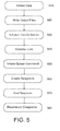
- FIG. 5 is a flowchart 500 illustrating an exemplary secure file upload of data between an onsite monitoring system and a central monitoring and diagnostic infrastructure in accordance with an embodiment of the disclosure.
- the low bandwidth export service may extract data from an archiver module.
- Block 510 is followed by block 520, in which the output files may be written to upload/download directories.
- block 530 an asynchronous background intelligent transfer service may be scheduled.
- the intelligent agent may establish a secure (certificates based) uni-directional (using networking port 443) TLS/SSL encrypted link between the OSM and the associated central file transfer servers.
- the intelligent agent may initiate a command upload message for asynchronous, concurrent, parallel files upload.
- Block 560 follows block 550, in which the intelligent agent may create associated HTTPS chunks and may send the datagrams serially over a preselected port (port 443 in this example) in block 570.
- the data transport reliability is performed via checksum (for each chunk and on the complete file) as well as by the retransmit and fault tolerance mechanisms provided by the underlying transport protocol stack.
- Block 580 follows block 570, in which the HTTPS datagrams may be reconstructed by the agent server service and presented to the low bandwidth import service.
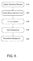
- FIG. 6 is a flowchart 600 illustrating an exemplary secure file download of data between an onsite monitoring system and a central monitoring and diagnostic infrastructure in accordance with an embodiment of the disclosure.
- the agent server initiates a file download request message within a reply to any previous message from the intelligent agent since the pre-selected traffic port (port 443) may be uni-directional (open outbound only).
- Block 610 is followed by block 620 in which the intelligent agent may initiate a download command message for asynchronous, concurrent, parallel files download.
- the agent server creates the associated HTTPS chunks and sends, in block 640, the datagrams serially over a port (port 443) using the connection previously opened by the intelligent agent.
- the data transport reliability is performed by the agent server via checksum (for each chunk and on the complete file) as well as by the retransmit and fault tolerance mechanisms provided by the underlying transport protocol stack.
- the HTTPS datagrams are reconstructed by the intelligent agent service and presented to the low bandwidth export service.
- FIG. 7 is a flowchart 700 illustrating an exemplary secure remote access to an onsite monitoring system. Communication security is provided using a TLS/SSL based tunneling methodology encapsulating the remote access session data.
- a user may request a remote desktop protocol (RDP) connection to the onsite monitoring system.
- RDP remote desktop protocol
- the agent server may initiate a RDP session request message within a reply to any previous message from the intelligent agent since the traffic port 443 is uni-directional (open outbound only).
- the intelligent agent connects to the RDP server on the onsite monitoring system.
- Block 740 follows block 730, in which the intelligent agent opens a TLS/SSL tunnel at the agent server.
- the data is encrypted using a validated crypto library, and in block 760, the intelligent agent completes the authentication process.
- the connection may be established.
- the end to end RDP connection may be established by connecting the intermediate connections between the onsite monitoring system RDP server, the intelligent agent, the agent server, and the end user computing device.
Landscapes
- Engineering & Computer Science (AREA)
- Computer Security & Cryptography (AREA)
- Computer Networks & Wireless Communication (AREA)
- Signal Processing (AREA)
- Computer Hardware Design (AREA)
- Computing Systems (AREA)
- General Engineering & Computer Science (AREA)
- Data Exchanges In Wide-Area Networks (AREA)
- Computer And Data Communications (AREA)
- Information Transfer Between Computers (AREA)
Abstract
Description
- This disclosure generally relates to communication security, and in particular to systems and methods for secure file transfers.
- Monitoring and diagnostic (M&D) centers can provide numerous services for power plant units as well as other assets. Such services may include asset monitoring, event tracking, trip event reporting, root cause classification, forced outage detection, diagnostics and reporting with various recommendations to a site. Raw operational data as well as post-processed data can be derived from analytics which may be used by various engineering teams for performance and reliability studies, warranty support, and engineering research and development.
- However, new requirements are being imposed for the large set of existing power plants requiring relatively secure file transfers. Many sites need to comply with North American Electric Reliability Corporation (NERC) or other regulatory security requirements and other communication security challenges. In addition, many of these sites have limited bandwidth connections and relatively unstable or otherwise unreliable links.
- Typically, the onsite monitoring is located within the power plant infrastructure. The onsite network is usually protected by firewalls and a proxy at the plant edge that may prevent inbound connections and thus enforcing that the onsite monitoring is non-routable. Furthermore, all standard bi-directional TCP / HTTP communication ports are usually blocked by the firewall to ensure the security of the system.
- Current communications typically require a bi-directional based communication ports schema, and current data transport technologies are generally not able to adequately deal with dial-up or low bandwidth network topologies (e.g. significant latency, bandwidth management under stress conditions). Furthermore, a uni-directional general purpose file transfer solution is not available.
- In order to meet new and ever growing customer security requirements, relatively secure file transfer solutions are needed to provide secure data transfer for transport of data between an onsite monitoring system and a central monitoring and diagnostic infrastructure. A secure file transfer package is needed to be deployed to support onsite monitoring sites with limited bandwidth connections and relatively unstable or otherwise unreliable links that can comply with NERC or other regulatory requirements and other communication security challenges.
- Some or all of the above needs may be addressed by certain embodiments of the disclosure. According to an example embodiment, there is disclosed a method for transferring data that may include collecting operational data by an onsite system behind a firewall, writing output files in a transfer directory, scheduling an asynchronous intelligent transfer service, establishing a secure certificate based uni-directional encrypted link between the onsite system and a central system, initiating a command upload message for asynchronous, concurrent parallel file upload, creating associated outbound datagrams, sending the outbound datagrams over a predetermined specific port, and reconstructing the outbound datagrams by the central system.
- The method may further include sending to an open outbound uni-directional port, by the central system, a file download request message within a reply to a previous message from the onsite system, initiating, by the onsite system, a download command message for asynchronous concurrent parallel files download, creating, by the central system, associated secure datagrams, sending the inbound datagrams serially over the port using a previously opened connection, and reconstructing the inbound datagrams by the onsite system.
- In another embodiment, a system for transferring data is disclosed. The system may comprise an onsite system behind a firewall. The onsite system may be operable to collect operational data, write files in a transfer directory, schedule an asynchronous intelligent transfer service, establish a secure certificate based uni-directional encrypted link between the onsite system and a central system, initiate a command upload message for asynchronous, concurrent parallel file upload, create associated outbound datagrams, and send the outbound datagrams over a predetermined specific port. The central system may be operable to reconstruct the outbound datagrams based at least in part on received outbound datagrams and send a file download request message within a reply to a previous message from the onsite system to an open outbound uni-directional port.
- Other embodiments, features, and aspects of the disclosure are described in detail herein and are considered a part of the claimed disclosure. Other embodiments, features, and aspects can be understood with reference to the following detailed description, accompanying drawings, and claims.
- References will now be made to the accompanying figures, which are not necessarily drawn to scale, and wherein:
-
FIG. 1 is a schematic block diagram of an example system architecture for providing secure data transfer for transport of data between an onsite monitoring system and a central monitoring and diagnostic infrastructure in accordance with an embodiment of the disclosure. -
FIG. 2 illustrates a schematic block diagram of an example onsite monitoring system in accordance with an embodiment of the disclosure. -
FIG. 3 illustrates a schematic block diagram of an example central monitoring and diagnostic infrastructure in accordance with an embodiment of the disclosure. -
FIG. 4 illustrates a functional block diagram of an example onsite monitoring system in accordance with an embodiment of the disclosure. -
FIG. 5 is a flowchart illustrating an exemplary secure file upload of data between an onsite monitoring system and a central monitoring and diagnostic infrastructure in accordance with an embodiment of the disclosure. -
FIG. 6 is a flowchart illustrating an exemplary secure file download of data between an onsite monitoring system and a central monitoring and diagnostic infrastructure in accordance with an embodiment of the disclosure. -
FIG. 7 is a flowchart illustrating an exemplary secure remote access to an onsite monitoring system. - Example embodiments of the disclosure now will be described more fully hereinafter with reference to the accompanying drawings, in which some, but not all embodiments are shown. Indeed, the disclosure may be embodied in many different forms and should not be construed as limited to the embodiments set forth herein; rather these embodiments are provided so that this disclosure will satisfy applicable legal requirements. Like numbers refer to like elements throughout.
- To achieve secure file transfers supporting onsite monitoring of power plants with limited bandwidth connections or relatively unstable or otherwise unreliable links, a new infrastructure combining various hardware, software, and networking technologies has been developed. Certain embodiments of the disclosure may have the technical effect of enabling asynchronous, service oriented, extraction of data from a repository on the onsite monitoring system and transferring data to a central storage repository for analytics processing. Another technical effect of certain embodiments of the disclosure may allow asynchronous, parallel, simultaneous downloading and uploading of files between designated servers in the central monitoring and diagnostic infrastructure and the onsite monitoring system while providing security, dynamic guarantee of service, and reliability features.
- Referring to
FIG. 1 of the drawings, there is shown schematic block diagram of anexample system architecture 100 for providing secure data transfer for transport of data between anonsite monitoring system 110 and a central monitoring and diagnostic infrastructure. - The
onsite monitoring system 110 may be implemented by using a Windows™ based platform 102 (typically a high computing server), with various networking capabilities and may be collocated at the power plant site behind acorporate firewall 108. Theonsite network 106 may be protected byfirewalls 108 and aproxy 104 at the plant edge preventing inbound connections and thus enforcing that the onsite monitoring is non-routable. Furthermore, all standard bi-directional TCP / HTTP communication ports may be blocked by thefirewall 108. - The onsite monitoring secure remote access solution may provide monitoring and
diagnostic users onsite monitoring system 110 and perform certain administration or management tasks. Communication security may be provided by integrating the HTTPS/TLS protocols stack with a customized software package referred to as an intelligent agent. - A
user 119 utilizing the central system Intranet 114 or aremote user 134 connected to the outside Internet 130 may establish a connection to aremote enterprise server 118. Theremote enterprise server 118 may establish a connection with anenterprise tunneling server 116. Theuser onsite monitoring system 110. Communication security may be provided using a TLS/SSL based tunneling methodology encapsulating the remote access session data. - An
M&D user 119 or a remote 134 may request an RDP connection to theonsite monitoring system 110. Since the traffic port 443 is uni-directional (open outbound only), theagent server 116 may initiate an RDP session request message within a reply to any previous message from anintelligent agent 102 residing on a server within theonsite monitoring system 110. Theintelligent agent 102 then may connect to a RDP module within the onsite monitoring system. - Referring to
FIG. 2 , illustrated is an example of onsite monitoring (OSM) 200 in accordance with an embodiment of the disclosure. The OSM 200 may be implemented on a Windows™ based platform (typically a high performance server), with various networking capabilities and is collocated at the power plant site behind the corporate firewalls. - Data
collection software modules 210 may be associated with the collection of the units' operational and dynamic data, such as temperature, pressure, flow rate, clearance (e.g., distance between two components) and vibration data of turbo-machinery. Various types of controllers, based on network connectivity capabilities and raw data resolution, are used to interface with the units sensors. The controller may range from theproprietary controllers 111 to standard Ethernet Data Acquisition Systems (EDAS) 113. The collected raw data may then be processed and transferred to other OSM modules via data hubs. The data hubs may collect tremendous volumes of real-time production information and perform supervisory automation along with delivery of reliable information to higher-level analytic applications. Such data hubs may include certain proprietary hubs such as WSST 115, CIMPLICITY 117 and the EHISTORIAN 119 collector modules. In addition, these modules can provide a combined source for data quality and time coherency. - The
storage software modules 220 may be associated with data storage and archiving. The software platform 22 can be a proprietary platform such as PROFICY HISTORIAN, and can provide the ability for local storage of time series data as well as processed data generated by the analytics outputs. It can also provide the ability to manage data quality using various compression and interpolation techniques. - The
data processing modules 230 may be associated with data processing as well as events and alarms escalation. Analytics based data processing may be provided by a proprietary platform, such as CENTRAL CONDITION ASSESSMENT PLATFORM - LOCAL EDITION (CCAP-LE) 231 and continuous diagnostic engine (CDE)rule engines platforms 233. Alarms and event escalation may be performed by anaction engine 235 and may be send notifications via email or web based services. - The
transfer modules 240 may be associated with data transfer to the central monitoring and diagnostic system. Two types of transport mechanisms are generally available based on site specific security requirements, network topology, and available bandwidth. The first mechanism may leverage ahistorian collector 241 to collector service to provide real time data streaming transport. The second mechanism combines the services provided by a low bandwidth andintelligent agent modules 243 for a secure (one way traffic/push), asynchronous, concurrent, and reliable files transport. - Accordingly, at least one technical effect may enable low bandwidth and intelligent agent modules to provide secure, one way traffic, asynchronous, concurrent, and reliable files transport.
-
FIG. 3 illustrates an example central monitoring anddiagnostic infrastructure 300 in accordance with an embodiment of the disclosure. - The central
system transfer modules 310 may be associated with data transfer from the onsite system. Two types of transport mechanisms are generally available. The first mechanism may leverage a historian collector tocollector service 311 to provide real time data streaming transport. The second mechanism may provide relatively lowbandwidth import services 313 for a relatively secure (one way traffic/push), asynchronous, concurrent, and reliable file transport. - The central
storage software modules 320 may be associated with the data storage and archiving of the time series data initially collected and transferred from the OSMs fleet. This software platform may provide the ability for storage of time series data as well as processed data generated by the analytics outputs. Thestorage module 320 may provide enterprise-wide data historian services that archives and distributes tremendous volumes of real-time production information at extremely high speeds. It may also provide the ability to manage data quality using various compression and interpolation techniques. - The central
storage software modules 320, such as PROFICY HISTORIAN, may be operable to compare years of historical data to real-time data to allow for a myriad of analysis possibilities. This solution may provide the tools to compare assets across a fleet and over long periods of time to better understand how equipment and processes are running versus how they should be running. - The remaining set of illustrated
modules 330 are a collection of configuration databases, monitoring and diagnostic operation visualization tools, analytics rule engines as well as the analytics runtime environment and associated application programming interfaces and service oriented architectures. - Referring to
FIG. 4 , illustrated is a functional block diagram of an exampleonsite manager 400 in accordance with an embodiment of the disclosure. Themanager 400 may include one ormore processors 402, one ormore memories 404, one or more input/output ("I/O") interfaces 406, and one or more network interfaces 408. Themanager 400 may include other devices not depicted. - The one or
more processors 402 may include one or more cores and is configured to access and execute at least in part instructions stored in the one ormore memories 404. The one ormore memories 404 can include one or more computer-readable storage media ("CRSM"). The one ormore memories 404 may include, but are not limited to, random access memory ("RAM"), flash RAM, magnetic media, optical media, and so forth. The one ormore memories 404 may be volatile in that information is retained while providing power or non-volatile in that information is retained without providing power. - The one or more I/O interfaces 406 may also be provided in the
manager 400. These I/O interfaces 406 can allow for coupling devices such as sensors, keyboards, mice, monitors, printers, external memories, and the like. The one or more I/O interfaces 406 may allow for coupling to various sensors and controllers that can provide operational data across the system. - The one or
more network interfaces 408 may provide for the transfer of data between themanager 400 and another device directly such as in a peer-to-peer fashion, via a network, or both. The one ormore network interfaces 408 may include, but are not limited to, personal area networks ("PANs"), wired local area networks ("LANs"), wide area networks ("WANs"), wireless local area networks ("WLANs"), wireless wide area networks ("WWANs"), and so forth. The one ormore network interfaces 408 may utilize acoustic, radio frequency, optical, or other signals to exchange data between themanager 400 and other devices, - The one or
more memories 404 may store instructions or modules for execution by the one ormore processors 402 to perform certain actions or functions. The following modules are included by way of illustration, and not as a limitation. Furthermore, while the modules are depicted as stored in thememory 404, in some implementations, these modules may be stored at least in part in external memory which is accessible to themanager 400 via the network interfaces 408 or the I/O interfaces 406. These modules may include anoperating system module 410 configured to manage hardware resources such as the I/O interfaces 406 and provide various services to applications or modules executing on theprocessor 402. - The
collection modules 414 may be stored in thememory 404. Themodules 414 may be configured to continuously acquire data from the one or more input devices and calculate various parameters. Thesoftware modules 414 may be associated with the collection of the units' operational and dynamic data such as temperature, pressure, flow rate, clearance (e.g., distance between two components) and vibration data of turbo-machinery. Various types of controllers (based on network connectivity capabilities / raw data resolution) are used to interface with the units sensors. The controllers can range from certain proprietary controllers, such as MARK controllers, to a standard Ethernet Data Acquisition System (EDAS). The collected raw data is then processed and transferred to other OSM modules via various data hubs. In addition, these modules may provide a combined source for data quality and time coherency. Themodule 414 may store the data and calculated estimates in thedatastore 412. - The
processing modules 416 may be configured to store and archive\e data. The software platform may provide the ability for local storage of time series data as well as processed data generated by the analytics outputs. It also may provide the ability to manage data quality using various compression and interpolation techniques. - The
transfer modules 418 may be configured transfer data to the central M&D system. A first mechanism may be configured for a collector to collector service that provides real time data streaming transport. A second mechanism may combine the services provided by a low bandwidth intelligent agent module for a secure (one way traffic/push), asynchronous, concurrent, and reliable files transport. - The
manager 400 described above with reference toFIG. 4 is provided by way of example only. As desired, numerous other embodiments, systems, methods, apparatus, and components may be utilized to control the gas turbine firing temperature below the critical temperature. -
FIG. 5 is a flowchart 500 illustrating an exemplary secure file upload of data between an onsite monitoring system and a central monitoring and diagnostic infrastructure in accordance with an embodiment of the disclosure. - In
block 510, the low bandwidth export service may extract data from an archiver module.Block 510 is followed byblock 520, in which the output files may be written to upload/download directories. Inblock 530, an asynchronous background intelligent transfer service may be scheduled. - In
block 540, the intelligent agent may establish a secure (certificates based) uni-directional (using networking port 443) TLS/SSL encrypted link between the OSM and the associated central file transfer servers. - In step, block, the intelligent agent may initiate a command upload message for asynchronous, concurrent, parallel files upload.
Block 560 followsblock 550, in which the intelligent agent may create associated HTTPS chunks and may send the datagrams serially over a preselected port (port 443 in this example) inblock 570. The data transport reliability is performed via checksum (for each chunk and on the complete file) as well as by the retransmit and fault tolerance mechanisms provided by the underlying transport protocol stack.Block 580 followsblock 570, in which the HTTPS datagrams may be reconstructed by the agent server service and presented to the low bandwidth import service. -
FIG. 6 is a flowchart 600 illustrating an exemplary secure file download of data between an onsite monitoring system and a central monitoring and diagnostic infrastructure in accordance with an embodiment of the disclosure. - In
block 610, the agent server initiates a file download request message within a reply to any previous message from the intelligent agent since the pre-selected traffic port (port 443) may be uni-directional (open outbound only).Block 610 is followed byblock 620 in which the intelligent agent may initiate a download command message for asynchronous, concurrent, parallel files download. Inblock 630, the agent server creates the associated HTTPS chunks and sends, inblock 640, the datagrams serially over a port (port 443) using the connection previously opened by the intelligent agent. The data transport reliability is performed by the agent server via checksum (for each chunk and on the complete file) as well as by the retransmit and fault tolerance mechanisms provided by the underlying transport protocol stack. Finally, inblock 650, the HTTPS datagrams are reconstructed by the intelligent agent service and presented to the low bandwidth export service. -
FIG. 7 is a flowchart 700 illustrating an exemplary secure remote access to an onsite monitoring system. Communication security is provided using a TLS/SSL based tunneling methodology encapsulating the remote access session data. - In
block 710, a user may request a remote desktop protocol (RDP) connection to the onsite monitoring system. Inblock 720, the agent server may initiate a RDP session request message within a reply to any previous message from the intelligent agent since the traffic port 443 is uni-directional (open outbound only). - In
block 730, the intelligent agent connects to the RDP server on the onsite monitoring system.Block 740 followsblock 730, in which the intelligent agent opens a TLS/SSL tunnel at the agent server. Inblock 750, the data is encrypted using a validated crypto library, and inblock 760, the intelligent agent completes the authentication process. Finally inblock 770, the connection may be established. The end to end RDP connection may be established by connecting the intermediate connections between the onsite monitoring system RDP server, the intelligent agent, the agent server, and the end user computing device. - The operations and processes described and shown above may be carried out or performed in any suitable order as desired in various implementations. Additionally, in certain implementations, at least a portion of the operations may be carried out in parallel. Furthermore, in certain implementations, less than or more than the operations described may be performed.
- This written description uses examples to disclose certain embodiments of the disclosure, including the best modes, and also to enable any person skilled in the art to practice certain embodiments of the disclosure, including making and using any devices or systems and performing any incorporated methods. The patentable scope of certain embodiments of the disclosure is defined in the claims, and may include other examples that occur to those skilled in the art. Such other examples are intended to be within the scope of the claims if they have structural elements that do not differ from the literal language of the claims, or if they include equivalent structural elements with insubstantial differences from the literal language of the claims.
Claims (15)
- A method (500) for transferring data, comprising:(a) collecting (510) operational data by an onsite system (110) behind a firewall (108);(b) writing (520) output files in a transfer directory;(c) scheduling (530) an asynchronous intelligent transfer service;(d) establishing (540) a secure certificate based uni-directional encrypted link between the onsite system (110) and a central system (114);(e) initiating (550) a command upload message for asynchronous, concurrent parallel file upload;(f) creating (560) associated outbound datagrams;(g) sending (570) the outbound datagrams over a predetermined specific port; and(h) reconstructing (580) the outbound datagrams by the central system (114).
- The method (500,600) of claim 1, further comprising:sending (610) to an open outbound uni-directional port, by the central system (114), a file download request message within a reply to a previous message from the onsite system (110);initiating (620), by the onsite system (110), a download command message for asynchronous concurrent parallel files download;creating (630), by the central system (114), associated secure datagrams;sending (640) the inbound datagrams serially over the port using a previously opened connection; andreconstructing (650) the inbound datagrams by the onsite system.
- The method (550,600) of claim 1, further comprising performing data transport reliability on the outbound datagrams via checksum by the central system (114) on each outbound datagram and at least one complete file.
- The method of claim 2 or 3, further comprising performing data transport reliability on the inbound datagrams via checksum by the onsite system (110) on each inbound datagram and at least one complete file.
- The method of any of claims 1 to 4, wherein sending (570) the outbound datagrams comprises sending the outbound datagrams via a low bandwidth service.
- The method of any preceding claim, wherein collecting (510) operational data comprises collecting the operational data from a plurality of onsite controllers (111) in communication with a plurality of sensors.
- The method of any preceding claim, wherein the firewall (108) prevents standard bi-directional transport control protocol communications.
- The method of any preceding claim, further comprising managing the data using interpolation and/or compression techniques.
- The method of any preceding claim, further comprising ensuring quality and time coherency of the operational data.
- The method of any preceding claim, further comprising performing analytics and diagnostics on the operational data.
- A computer program comprising computer program code means adapted to perform the steps of (a) to (g) of the method of claim 1 and the steps of claims 4, 5, 6, 8 and 9 when executed by a computer.
- A computer program computer comprising computer program code means adapted to perform step (h) of claim 1 and the steps of claims 2, 3 and 10 when executed by a computer.
- The computer program of claim 11, embodied on a computer-readable medium.
- The computer program of claim 12, embodied on a computer-readable medium.
- A system (100) for transferring data, comprising:an onsite system (110) behind a firewall (108), the onsite system (110) operable to execute the computer program of claim 11; anda central system (114) operable to execute the computer program of claim 12.
Applications Claiming Priority (1)
| Application Number | Priority Date | Filing Date | Title |
|---|---|---|---|
| US14/072,425 US9306915B2 (en) | 2013-11-05 | 2013-11-05 | Systems and methods for secure file transfers |
Publications (2)
| Publication Number | Publication Date |
|---|---|
| EP2869529A1 true EP2869529A1 (en) | 2015-05-06 |
| EP2869529B1 EP2869529B1 (en) | 2016-08-31 |
Family
ID=51868815
Family Applications (1)
| Application Number | Title | Priority Date | Filing Date |
|---|---|---|---|
| EP14191515.7A Active EP2869529B1 (en) | 2013-11-05 | 2014-11-03 | Systems and methods for secure file transfers |
Country Status (4)
| Country | Link |
|---|---|
| US (1) | US9306915B2 (en) |
| EP (1) | EP2869529B1 (en) |
| JP (1) | JP6496522B2 (en) |
| CN (1) | CN104618320B (en) |
Families Citing this family (5)
| Publication number | Priority date | Publication date | Assignee | Title |
|---|---|---|---|---|
| US10496517B2 (en) * | 2014-02-04 | 2019-12-03 | ZeroTurnaround AS | System and method for providing runtime diagnostics of executing applications |
| CN111147575B (en) * | 2019-12-25 | 2022-12-13 | 山东公链信息科技有限公司 | Data storage system based on block chain |
| US20220191256A1 (en) * | 2020-12-16 | 2022-06-16 | Ncr Corporation | Agnostic data collection platform |
| CN114979113B (en) * | 2021-02-23 | 2023-12-15 | 华为技术有限公司 | File transmission method, device and system |
| CN114338246B (en) * | 2022-03-14 | 2022-06-07 | 章和技术(广州)有限公司 | Firewall strategy auditing method, device, equipment and storage medium |
Citations (4)
| Publication number | Priority date | Publication date | Assignee | Title |
|---|---|---|---|---|
| WO2007044832A2 (en) * | 2005-10-07 | 2007-04-19 | Codeux, Inc. | Port access using user datagram protocol packets |
| CN201188626Y (en) * | 2007-10-11 | 2009-01-28 | 上海电气电站设备有限公司 | System for remotely monitoring and analyzing nuclear electricity steam turbine regulation system |
| US20110314272A1 (en) * | 2010-06-17 | 2011-12-22 | Klaus Nagel | Secure transfer of business data to a hosted system |
| WO2013012654A2 (en) * | 2011-07-15 | 2013-01-24 | Vmware, Inc. | Native viewer use for service results from a remote desktop |
Family Cites Families (13)
| Publication number | Priority date | Publication date | Assignee | Title |
|---|---|---|---|---|
| US6553422B1 (en) * | 1999-04-26 | 2003-04-22 | Hewlett-Packard Development Co., L.P. | Reverse HTTP connections for device management outside a firewall |
| JP2001186912A (en) * | 1999-10-19 | 2001-07-10 | Kazuo Toyoda | Umbrella with brim |
| US7536715B2 (en) * | 2001-05-25 | 2009-05-19 | Secure Computing Corporation | Distributed firewall system and method |
| DE20211995U1 (en) | 2001-08-07 | 2003-01-16 | Innominate Security Technologies AG, 12489 Berlin | Computer system for securing communication in networks |
| US7536548B1 (en) * | 2002-06-04 | 2009-05-19 | Rockwell Automation Technologies, Inc. | System and methodology providing multi-tier-security for network data exchange with industrial control components |
| ES2348260T3 (en) * | 2003-01-31 | 2010-12-02 | Visto Corporation | ASYNCHRON DATA RECOVERY IN REAL TIME. |
| US7814310B2 (en) * | 2003-04-12 | 2010-10-12 | Cavium Networks | IPsec performance optimization |
| US20080109889A1 (en) | 2003-07-01 | 2008-05-08 | Andrew Bartels | Methods, systems and devices for securing supervisory control and data acquisition (SCADA) communications |
| US7565526B1 (en) * | 2005-02-03 | 2009-07-21 | Sun Microsystems, Inc. | Three component secure tunnel |
| EP2279465B1 (en) | 2008-04-17 | 2014-04-02 | Siemens Aktiengesellschaft | Method and system for cyber security management of industrial control systems |
| US8683053B2 (en) * | 2010-12-28 | 2014-03-25 | Sonus Networks, Inc. | Methods and apparatus for establishing secure communications between client computing devices that use transport and security protocols |
| JPWO2013042412A1 (en) * | 2011-09-22 | 2015-03-26 | Necソリューションイノベータ株式会社 | COMMUNICATION SYSTEM, COMMUNICATION METHOD, AND PROGRAM |
| US9380023B2 (en) * | 2013-05-13 | 2016-06-28 | Owl Computing Technologies, Inc. | Enterprise cross-domain solution having configurable data filters |
-
2013
- 2013-11-05 US US14/072,425 patent/US9306915B2/en active Active
-
2014
- 2014-10-29 JP JP2014219873A patent/JP6496522B2/en active Active
- 2014-11-03 EP EP14191515.7A patent/EP2869529B1/en active Active
- 2014-11-05 CN CN201410615389.0A patent/CN104618320B/en active Active
Patent Citations (4)
| Publication number | Priority date | Publication date | Assignee | Title |
|---|---|---|---|---|
| WO2007044832A2 (en) * | 2005-10-07 | 2007-04-19 | Codeux, Inc. | Port access using user datagram protocol packets |
| CN201188626Y (en) * | 2007-10-11 | 2009-01-28 | 上海电气电站设备有限公司 | System for remotely monitoring and analyzing nuclear electricity steam turbine regulation system |
| US20110314272A1 (en) * | 2010-06-17 | 2011-12-22 | Klaus Nagel | Secure transfer of business data to a hosted system |
| WO2013012654A2 (en) * | 2011-07-15 | 2013-01-24 | Vmware, Inc. | Native viewer use for service results from a remote desktop |
Also Published As
| Publication number | Publication date |
|---|---|
| EP2869529B1 (en) | 2016-08-31 |
| US9306915B2 (en) | 2016-04-05 |
| JP2015091129A (en) | 2015-05-11 |
| JP6496522B2 (en) | 2019-04-03 |
| US20150127941A1 (en) | 2015-05-07 |
| CN104618320A (en) | 2015-05-13 |
| CN104618320B (en) | 2019-07-09 |
Similar Documents
| Publication | Publication Date | Title |
|---|---|---|
| EP2869530B1 (en) | Systems and methods for secure remote access | |
| US9838476B2 (en) | On-premise data collection and ingestion using industrial cloud agents | |
| US10764255B2 (en) | Secure command execution from a cloud monitoring system to a remote cloud agent | |
| EP2869529B1 (en) | Systems and methods for secure file transfers | |
| EP2924574B1 (en) | Unified data ingestion adapter for migration of industrial data to a cloud platform | |
| US12107836B2 (en) | Secure remote access to historical data | |
| US12035209B2 (en) | Method for wireless event-driven everything-to-everything (X2X) payload delivery | |
| CN119065918A (en) | One-key inspection method and system for computer monitoring system | |
| CN117914648A (en) | Method, device, processor and VPN device for optimizing VPN device | |
| CN115967175B (en) | Edge data acquisition control device and method for energy storage power station | |
| CN115580664B (en) | A data acquisition method, apparatus, device, and medium | |
| WO2020222845A1 (en) | External module for network connection to programmable logic controller (plc) backplane | |
| CN116149293A (en) | A vehicle remote diagnosis method, system and computer equipment | |
| Farhan et al. | Efficient Data Transmission and Remote Monitoring System for IoT Applications | |
| CN117834345A (en) | Rail transit control system, edge computing gateway, method and storage medium | |
| CN119728812A (en) | System and method for converting and processing remote signaling data of gateway equipment of virtual power plant | |
| CN118353918A (en) | Vehicle data collection and processing method, device, terminal and storage medium | |
| CN118467630A (en) | A sewage treatment site edge computing system and method under cloud-edge fusion architecture | |
| CN119629183A (en) | Data transmission method, device, equipment and storage medium | |
| CN103529784A (en) | Remote centralized control system |
Legal Events
| Date | Code | Title | Description |
|---|---|---|---|
| PUAI | Public reference made under article 153(3) epc to a published international application that has entered the european phase |
Free format text: ORIGINAL CODE: 0009012 |
|
| 17P | Request for examination filed |
Effective date: 20141103 |
|
| AK | Designated contracting states |
Kind code of ref document: A1 Designated state(s): AL AT BE BG CH CY CZ DE DK EE ES FI FR GB GR HR HU IE IS IT LI LT LU LV MC MK MT NL NO PL PT RO RS SE SI SK SM TR |
|
| AX | Request for extension of the european patent |
Extension state: BA ME |
|
| R17P | Request for examination filed (corrected) |
Effective date: 20151106 |
|
| RBV | Designated contracting states (corrected) |
Designated state(s): AL AT BE BG CH CY CZ DE DK EE ES FI FR GB GR HR HU IE IS IT LI LT LU LV MC MK MT NL NO PL PT RO RS SE SI SK SM TR |
|
| GRAP | Despatch of communication of intention to grant a patent |
Free format text: ORIGINAL CODE: EPIDOSNIGR1 |
|
| INTG | Intention to grant announced |
Effective date: 20160415 |
|
| GRAS | Grant fee paid |
Free format text: ORIGINAL CODE: EPIDOSNIGR3 |
|
| GRAA | (expected) grant |
Free format text: ORIGINAL CODE: 0009210 |
|
| AK | Designated contracting states |
Kind code of ref document: B1 Designated state(s): AL AT BE BG CH CY CZ DE DK EE ES FI FR GB GR HR HU IE IS IT LI LT LU LV MC MK MT NL NO PL PT RO RS SE SI SK SM TR |
|
| REG | Reference to a national code |
Ref country code: CH Ref legal event code: EP Ref country code: GB Ref legal event code: FG4D |
|
| REG | Reference to a national code |
Ref country code: IE Ref legal event code: FG4D |
|
| REG | Reference to a national code |
Ref country code: DE Ref legal event code: R096 Ref document number: 602014003381 Country of ref document: DE |
|
| REG | Reference to a national code |
Ref country code: AT Ref legal event code: REF Ref document number: 825846 Country of ref document: AT Kind code of ref document: T Effective date: 20161015 |
|
| REG | Reference to a national code |
Ref country code: FR Ref legal event code: PLFP Year of fee payment: 3 |
|
| REG | Reference to a national code |
Ref country code: LT Ref legal event code: MG4D |
|
| REG | Reference to a national code |
Ref country code: NL Ref legal event code: MP Effective date: 20160831 |
|
| REG | Reference to a national code |
Ref country code: AT Ref legal event code: MK05 Ref document number: 825846 Country of ref document: AT Kind code of ref document: T Effective date: 20160831 |
|
| PG25 | Lapsed in a contracting state [announced via postgrant information from national office to epo] |
Ref country code: LT Free format text: LAPSE BECAUSE OF FAILURE TO SUBMIT A TRANSLATION OF THE DESCRIPTION OR TO PAY THE FEE WITHIN THE PRESCRIBED TIME-LIMIT Effective date: 20160831 Ref country code: NO Free format text: LAPSE BECAUSE OF FAILURE TO SUBMIT A TRANSLATION OF THE DESCRIPTION OR TO PAY THE FEE WITHIN THE PRESCRIBED TIME-LIMIT Effective date: 20161130 Ref country code: FI Free format text: LAPSE BECAUSE OF FAILURE TO SUBMIT A TRANSLATION OF THE DESCRIPTION OR TO PAY THE FEE WITHIN THE PRESCRIBED TIME-LIMIT Effective date: 20160831 Ref country code: HR Free format text: LAPSE BECAUSE OF FAILURE TO SUBMIT A TRANSLATION OF THE DESCRIPTION OR TO PAY THE FEE WITHIN THE PRESCRIBED TIME-LIMIT Effective date: 20160831 Ref country code: RS Free format text: LAPSE BECAUSE OF FAILURE TO SUBMIT A TRANSLATION OF THE DESCRIPTION OR TO PAY THE FEE WITHIN THE PRESCRIBED TIME-LIMIT Effective date: 20160831 |
|
| PG25 | Lapsed in a contracting state [announced via postgrant information from national office to epo] |
Ref country code: LV Free format text: LAPSE BECAUSE OF FAILURE TO SUBMIT A TRANSLATION OF THE DESCRIPTION OR TO PAY THE FEE WITHIN THE PRESCRIBED TIME-LIMIT Effective date: 20160831 Ref country code: GR Free format text: LAPSE BECAUSE OF FAILURE TO SUBMIT A TRANSLATION OF THE DESCRIPTION OR TO PAY THE FEE WITHIN THE PRESCRIBED TIME-LIMIT Effective date: 20161201 Ref country code: SE Free format text: LAPSE BECAUSE OF FAILURE TO SUBMIT A TRANSLATION OF THE DESCRIPTION OR TO PAY THE FEE WITHIN THE PRESCRIBED TIME-LIMIT Effective date: 20160831 Ref country code: BE Free format text: LAPSE BECAUSE OF NON-PAYMENT OF DUE FEES Effective date: 20161130 Ref country code: AT Free format text: LAPSE BECAUSE OF FAILURE TO SUBMIT A TRANSLATION OF THE DESCRIPTION OR TO PAY THE FEE WITHIN THE PRESCRIBED TIME-LIMIT Effective date: 20160831 Ref country code: NL Free format text: LAPSE BECAUSE OF FAILURE TO SUBMIT A TRANSLATION OF THE DESCRIPTION OR TO PAY THE FEE WITHIN THE PRESCRIBED TIME-LIMIT Effective date: 20160831 |
|
| PG25 | Lapsed in a contracting state [announced via postgrant information from national office to epo] |
Ref country code: EE Free format text: LAPSE BECAUSE OF FAILURE TO SUBMIT A TRANSLATION OF THE DESCRIPTION OR TO PAY THE FEE WITHIN THE PRESCRIBED TIME-LIMIT Effective date: 20160831 Ref country code: RO Free format text: LAPSE BECAUSE OF FAILURE TO SUBMIT A TRANSLATION OF THE DESCRIPTION OR TO PAY THE FEE WITHIN THE PRESCRIBED TIME-LIMIT Effective date: 20160831 |
|
| PG25 | Lapsed in a contracting state [announced via postgrant information from national office to epo] |
Ref country code: BG Free format text: LAPSE BECAUSE OF FAILURE TO SUBMIT A TRANSLATION OF THE DESCRIPTION OR TO PAY THE FEE WITHIN THE PRESCRIBED TIME-LIMIT Effective date: 20161130 Ref country code: CZ Free format text: LAPSE BECAUSE OF FAILURE TO SUBMIT A TRANSLATION OF THE DESCRIPTION OR TO PAY THE FEE WITHIN THE PRESCRIBED TIME-LIMIT Effective date: 20160831 Ref country code: PT Free format text: LAPSE BECAUSE OF FAILURE TO SUBMIT A TRANSLATION OF THE DESCRIPTION OR TO PAY THE FEE WITHIN THE PRESCRIBED TIME-LIMIT Effective date: 20170102 Ref country code: SM Free format text: LAPSE BECAUSE OF FAILURE TO SUBMIT A TRANSLATION OF THE DESCRIPTION OR TO PAY THE FEE WITHIN THE PRESCRIBED TIME-LIMIT Effective date: 20160831 Ref country code: DK Free format text: LAPSE BECAUSE OF FAILURE TO SUBMIT A TRANSLATION OF THE DESCRIPTION OR TO PAY THE FEE WITHIN THE PRESCRIBED TIME-LIMIT Effective date: 20160831 Ref country code: PL Free format text: LAPSE BECAUSE OF FAILURE TO SUBMIT A TRANSLATION OF THE DESCRIPTION OR TO PAY THE FEE WITHIN THE PRESCRIBED TIME-LIMIT Effective date: 20160831 Ref country code: SK Free format text: LAPSE BECAUSE OF FAILURE TO SUBMIT A TRANSLATION OF THE DESCRIPTION OR TO PAY THE FEE WITHIN THE PRESCRIBED TIME-LIMIT Effective date: 20160831 Ref country code: BE Free format text: LAPSE BECAUSE OF FAILURE TO SUBMIT A TRANSLATION OF THE DESCRIPTION OR TO PAY THE FEE WITHIN THE PRESCRIBED TIME-LIMIT Effective date: 20160831 |
|
| REG | Reference to a national code |
Ref country code: DE Ref legal event code: R097 Ref document number: 602014003381 Country of ref document: DE |
|
| PG25 | Lapsed in a contracting state [announced via postgrant information from national office to epo] |
Ref country code: IT Free format text: LAPSE BECAUSE OF FAILURE TO SUBMIT A TRANSLATION OF THE DESCRIPTION OR TO PAY THE FEE WITHIN THE PRESCRIBED TIME-LIMIT Effective date: 20160831 |
|
| PLBE | No opposition filed within time limit |
Free format text: ORIGINAL CODE: 0009261 |
|
| STAA | Information on the status of an ep patent application or granted ep patent |
Free format text: STATUS: NO OPPOSITION FILED WITHIN TIME LIMIT |
|
| 26N | No opposition filed |
Effective date: 20170601 |
|
| REG | Reference to a national code |
Ref country code: IE Ref legal event code: MM4A |
|
| PG25 | Lapsed in a contracting state [announced via postgrant information from national office to epo] |
Ref country code: SI Free format text: LAPSE BECAUSE OF FAILURE TO SUBMIT A TRANSLATION OF THE DESCRIPTION OR TO PAY THE FEE WITHIN THE PRESCRIBED TIME-LIMIT Effective date: 20160831 |
|
| PG25 | Lapsed in a contracting state [announced via postgrant information from national office to epo] |
Ref country code: LU Free format text: LAPSE BECAUSE OF NON-PAYMENT OF DUE FEES Effective date: 20161130 |
|
| REG | Reference to a national code |
Ref country code: FR Ref legal event code: PLFP Year of fee payment: 4 |
|
| PG25 | Lapsed in a contracting state [announced via postgrant information from national office to epo] |
Ref country code: IE Free format text: LAPSE BECAUSE OF NON-PAYMENT OF DUE FEES Effective date: 20161103 |
|
| PG25 | Lapsed in a contracting state [announced via postgrant information from national office to epo] |
Ref country code: ES Free format text: LAPSE BECAUSE OF NON-PAYMENT OF DUE FEES Effective date: 20171104 Ref country code: HU Free format text: LAPSE BECAUSE OF FAILURE TO SUBMIT A TRANSLATION OF THE DESCRIPTION OR TO PAY THE FEE WITHIN THE PRESCRIBED TIME-LIMIT; INVALID AB INITIO Effective date: 20141103 |
|
| PG25 | Lapsed in a contracting state [announced via postgrant information from national office to epo] |
Ref country code: MK Free format text: LAPSE BECAUSE OF FAILURE TO SUBMIT A TRANSLATION OF THE DESCRIPTION OR TO PAY THE FEE WITHIN THE PRESCRIBED TIME-LIMIT Effective date: 20160831 Ref country code: MC Free format text: LAPSE BECAUSE OF FAILURE TO SUBMIT A TRANSLATION OF THE DESCRIPTION OR TO PAY THE FEE WITHIN THE PRESCRIBED TIME-LIMIT Effective date: 20160831 Ref country code: IS Free format text: LAPSE BECAUSE OF FAILURE TO SUBMIT A TRANSLATION OF THE DESCRIPTION OR TO PAY THE FEE WITHIN THE PRESCRIBED TIME-LIMIT Effective date: 20160831 Ref country code: CY Free format text: LAPSE BECAUSE OF FAILURE TO SUBMIT A TRANSLATION OF THE DESCRIPTION OR TO PAY THE FEE WITHIN THE PRESCRIBED TIME-LIMIT Effective date: 20160831 |
|
| PG25 | Lapsed in a contracting state [announced via postgrant information from national office to epo] |
Ref country code: CH Free format text: LAPSE BECAUSE OF NON-PAYMENT OF DUE FEES Effective date: 20171130 Ref country code: LI Free format text: LAPSE BECAUSE OF NON-PAYMENT OF DUE FEES Effective date: 20171130 |
|
| PG25 | Lapsed in a contracting state [announced via postgrant information from national office to epo] |
Ref country code: MT Free format text: LAPSE BECAUSE OF NON-PAYMENT OF DUE FEES Effective date: 20161103 |
|
| REG | Reference to a national code |
Ref country code: FR Ref legal event code: PLFP Year of fee payment: 5 |
|
| PG25 | Lapsed in a contracting state [announced via postgrant information from national office to epo] |
Ref country code: AL Free format text: LAPSE BECAUSE OF FAILURE TO SUBMIT A TRANSLATION OF THE DESCRIPTION OR TO PAY THE FEE WITHIN THE PRESCRIBED TIME-LIMIT Effective date: 20160831 Ref country code: TR Free format text: LAPSE BECAUSE OF FAILURE TO SUBMIT A TRANSLATION OF THE DESCRIPTION OR TO PAY THE FEE WITHIN THE PRESCRIBED TIME-LIMIT Effective date: 20160831 |
|
| PG25 | Lapsed in a contracting state [announced via postgrant information from national office to epo] |
Ref country code: ES Free format text: LAPSE BECAUSE OF FAILURE TO SUBMIT A TRANSLATION OF THE DESCRIPTION OR TO PAY THE FEE WITHIN THE PRESCRIBED TIME-LIMIT Effective date: 20160831 |
|
| REG | Reference to a national code |
Ref country code: DE Ref legal event code: R079 Ref document number: 602014003381 Country of ref document: DE Free format text: PREVIOUS MAIN CLASS: H04L0029060000 Ipc: H04L0065000000 |
|
| PGFP | Annual fee paid to national office [announced via postgrant information from national office to epo] |
Ref country code: DE Payment date: 20251128 Year of fee payment: 12 |
|
| PGFP | Annual fee paid to national office [announced via postgrant information from national office to epo] |
Ref country code: GB Payment date: 20251127 Year of fee payment: 12 |
|
| PGFP | Annual fee paid to national office [announced via postgrant information from national office to epo] |
Ref country code: FR Payment date: 20251125 Year of fee payment: 12 |