EP2869498A1 - Network management system - Google Patents
Network management system Download PDFInfo
- Publication number
- EP2869498A1 EP2869498A1 EP13810727.1A EP13810727A EP2869498A1 EP 2869498 A1 EP2869498 A1 EP 2869498A1 EP 13810727 A EP13810727 A EP 13810727A EP 2869498 A1 EP2869498 A1 EP 2869498A1
- Authority
- EP
- European Patent Office
- Prior art keywords
- field wireless
- synchronizing
- wireless management
- stations
- cable
- Prior art date
- Legal status (The legal status is an assumption and is not a legal conclusion. Google has not performed a legal analysis and makes no representation as to the accuracy of the status listed.)
- Granted
Links
Images


Classifications
-
- H—ELECTRICITY
- H04—ELECTRIC COMMUNICATION TECHNIQUE
- H04L—TRANSMISSION OF DIGITAL INFORMATION, e.g. TELEGRAPHIC COMMUNICATION
- H04L12/00—Data switching networks
- H04L12/28—Data switching networks characterised by path configuration, e.g. LAN [Local Area Networks] or WAN [Wide Area Networks]
- H04L12/40—Bus networks
- H04L12/40169—Flexible bus arrangements
- H04L12/40176—Flexible bus arrangements involving redundancy
- H04L12/40182—Flexible bus arrangements involving redundancy by using a plurality of communication lines
-
- H—ELECTRICITY
- H04—ELECTRIC COMMUNICATION TECHNIQUE
- H04L—TRANSMISSION OF DIGITAL INFORMATION, e.g. TELEGRAPHIC COMMUNICATION
- H04L41/00—Arrangements for maintenance, administration or management of data switching networks, e.g. of packet switching networks
- H04L41/04—Network management architectures or arrangements
-
- H—ELECTRICITY
- H04—ELECTRIC COMMUNICATION TECHNIQUE
- H04L—TRANSMISSION OF DIGITAL INFORMATION, e.g. TELEGRAPHIC COMMUNICATION
- H04L41/00—Arrangements for maintenance, administration or management of data switching networks, e.g. of packet switching networks
- H04L41/06—Management of faults, events, alarms or notifications
- H04L41/0654—Management of faults, events, alarms or notifications using network fault recovery
-
- H—ELECTRICITY
- H04—ELECTRIC COMMUNICATION TECHNIQUE
- H04W—WIRELESS COMMUNICATION NETWORKS
- H04W24/00—Supervisory, monitoring or testing arrangements
- H04W24/04—Arrangements for maintaining operational condition
-
- H—ELECTRICITY
- H04—ELECTRIC COMMUNICATION TECHNIQUE
- H04L—TRANSMISSION OF DIGITAL INFORMATION, e.g. TELEGRAPHIC COMMUNICATION
- H04L12/00—Data switching networks
- H04L12/28—Data switching networks characterised by path configuration, e.g. LAN [Local Area Networks] or WAN [Wide Area Networks]
- H04L12/46—Interconnection of networks
- H04L12/4604—LAN interconnection over a backbone network, e.g. Internet, Frame Relay
- H04L12/462—LAN interconnection over a bridge based backbone
-
- H—ELECTRICITY
- H04—ELECTRIC COMMUNICATION TECHNIQUE
- H04L—TRANSMISSION OF DIGITAL INFORMATION, e.g. TELEGRAPHIC COMMUNICATION
- H04L12/00—Data switching networks
- H04L12/28—Data switching networks characterised by path configuration, e.g. LAN [Local Area Networks] or WAN [Wide Area Networks]
- H04L12/40—Bus networks
- H04L2012/4026—Bus for use in automation systems
Definitions
- the present invention relates to a network management system, and more particularly to a redundancy of a field wireless management function.
- a communication between a field device and a control system in a process control system progresses to a wireless represented by a wireless communication standard ISA100.11a for an industrial automation which is determined by an ISA100 committee of an international learned society of instrumentation control (ISA: International Society of Automation) and issued in September, 2009 via a hybrid communication such as HART (a registered trademark) that a digital signal is superimposed on an analog communication of 4 to 20 mA and a digital communication such as FOUNDATION Fieldbus (a registered trademark) or PROFIBUS (a registered trademark) from an analog communication of 4 to 20 mA by a two-wire type signal wire.
- HART a registered trademark
- FOUNDATION Fieldbus a registered trademark
- PROFIBUS PROFIBUS
- a quantity of information that can be used by a plant operation is outstandingly actively increased.
- versatile information such as a plurality of process quantities or diagnosis results which are transmitted by devices can be sent to a host system such as a DCS (Distributed Control System) or a device management system, so that facilities can be managed, previewed and maintained.
- DCS Distributed Control System
- a device management system so that facilities can be managed, previewed and maintained.
- a field wireless technology that makes the communication between the field device and the control system wireless has many merits, in addition to the above-described merits, for instance, a wiring or an engineering cost can be reduced, devices can be installed in places where the wiring is difficult, and the devices are easily added or removed.
- a wiring or an engineering cost can be reduced
- devices can be installed in places where the wiring is difficult, and the devices are easily added or removed.
- a field wireless management station in which a gateway function and a system management function are incorporated is made to be redundant.
- Fig. 6 is an explanatory view of a structure which shows an example of a conventional redundant connection of the field wireless management station.
- the field wireless management stations 11 and 12 have the gateway functions and the system management functions incorporated.
- Main modules 11a and 12a and switch modules 11b and 12b are shown which are provided to realize these functions.
- the field wireless management stations 11 and 12 are connected to a host network NW1 and connected to a synchronizing network NW2 to take synchronization between the field wireless management stations, and further connected to a backbone network NW3 including four layer-2-switches SW1 to SW4 which are connected together in the form of a loop to connect backbone routers 21 and 22 thereto.
- the field wireless management stations 11 and 12 and the backbone routers 21 and 22 are respectively formed to be redundant.
- the four layer-2-switches SW1 to SW4 connected together in the form of the loop which form the backbone network NW3 can open an arbitrary port in accordance with, for instance, an RSTP (rapid spanning tree protocol).
- RSTP rapid spanning tree protocol
- the failed port may be selectively opened and bypassed to continuously carry out a communication.
- Patent literature 1 discloses a technique that simplifies an establishment of a connection in a system which accesses to other system through an addressable and redundant gateway.
- Patent literature 2 discloses a technique that early detects a failure of a duplex gateway by alternately using the duplex gateway.
- Non-Patent Literature 1 Shuji Yamamoto and two other members, "Field Wireless Solution Based On ISA100.11a Which Reforms Instrumentation”, Yokogawa Technical Information, Yokogawa Electric Corporation, 2010, Vol. 53 No. 2 (2010) P.7-p.12
- Non-Patent Literature 2 Shuji Yamamoto and three other members, "World's First Wireless Field Instruments Based on ISA100.11a", Yokogawa Technical Report, Yokogawa Electric Corporation, 2010. Vol.53 No. 2(2010) p.13-p.16
- the present invention is devised by paying attention to these problems and it is an object of the present invention to realize a network management system which can suppress to a minimum a time during which it is impossible to make a communication when a trouble occurs in any of field wireless management stations formed to be redundant.
- a network management system in which field wireless management stations having gateway functions and system management functions incorporated are redundantly connected together, wherein the field wireless management stations include at least switch modules, and the plurality of field wireless management stations are connected to each other through a synchronizing cable and synchronizing connectors provided in the synchronizing cable, and switches are connected in series to a synchronizing system which connects the switch modules to each other to turn on and off the system.
- the backbone routers when the switch provided in the synchronizing system which connects the switch modules to each other is turned on, the backbone routers can be respectively directly connected to the field wireless management stations. When the switch is turned off, the backbone routers can be respectively connected to the field wireless management stations through the layer-2-switches which are connected in the form of a loop.
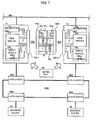
- Fig. 1 is an explanatory view of a structure showing one exemplary embodiment of the present invention. Parts common to those shown in Fig. 6 are designated by the same reference numerals.
- the network management system according to the present exemplary embodiment is a network management system in which field wireless management stations having gateway functions and system management functions incorporated are redundantly connected to each other. As shown in Fig. 1 , in the field wireless management stations 11 and 12 of the network management system according to the present exemplary embodiment, pin identifying parts 11c and 12c, main modules 11a and 12a, switch modules 11b and 12b and connectors CN 11 and CN 12 are respectively provided.
- a synchronizing cable 30 is connected to the connectors CN 11 and CN 12, so that the main modules 11a and 12a and the switch modules 11b and 12b of the filed wireless management stations 11 and 12 are respectively connected to each other through the synchronizing cable 30.
- pins of the connectors CN 11 and CN 12 that are respectively connected to the pin identifying parts 11c and 12c are different from each other.
- the main module 11a, the switch module 11b and the pin identifying part 11c which form the field wireless management station 11 are mutually connected together through an inner bus not shown in the drawing. Further, the main module 12a, the switch module 12b and the pin identifying part 12c which form the field wireless management station 12 are also mutually connected together through an inner bus not shown in the drawing.
- a connector CNa is provided which is fitted and connected to the connector CN 11 of the one field wireless management station 11.
- a connector CNb is provided which is fitted and connected to the connector CN 12 of the other field wireless management station 12.
- a first group of signal wires Pa which connect the main modules 11 a and 12a to each other and a second group of signal wires Pb which connect the switch module 11b and 12b to each other.
- a third group of signal wires Pc1 are provided which identify the one field wireless management station 11.
- a fourth group of signal wires Pc2 are provided which identify the other field wireless management station 12.
- switches SWm are provided which are connected in series to the second group of signal wires Pb for connecting the switch modules 11b and 12b to each other to turn on and off the group of signal wires
- backbone routers 21 and 22 are redundantly connected to the field wireless management stations 11 and 12 through a backbone network NW3 including four layer-2-switches SW1 to SW4 which are connected together in the form of a loop, and the switches SWm are set to off states.
- Figs. 2(A) and 2(B) show enlarged views of the groups of signal wires for identifying the field wireless management stations 11 and 12.
- Fig. 2(A) shows the third group of signal wires Pc1
- Fig. 2(B) shows the fourth group of signal wires Pc2.
- signal wires Pc11 and Pc12 are short-circuit connected to each other.
- signal wires Pc21 and Pc23 are connected to each other in a short-circuit state.
- the main modules 11a and 12a are formed with a CPU or a memory. On the main modules 11 a and 12a, an OS operates. The main modules 11 a and 12a communicate with each other through the synchronizing cable 30 to make equalization of various kinds of information.
- main modules 11 a and 12a periodically monitor the fitted and connected states of the connectors CNa and CNb of the synchronizing cable 30 to the connectors CN 11 and CN 12 respectively through the inner buses not shown in the drawing.
- the switch modules 11b and 12b are network switches (hubs) and connected to each other through the synchronizing cable 30.
- the switches SWm are set to off states as mentioned above.
- Fig. 3 is an explanatory view of a redundant connection in the structure shown in Fig. 1 .
- the backbone routers 21 and 22 are redundantly connected to the field wireless management stations 11 and 12 through the backbone network NW3 formed with the four layer-2-switches SW1 to SW4 which are connected together in the form of a loop.
- the backbone router 21 is connected to the field wireless management station 11 through a rout A or D shown in Fig. 3 , and connected to the field wireless management station 12 through a route B or C.
- the above-described symbol A designates the route passing through the layer-2-switches respectively in order of SW4 and SW1.
- the above-described symbol D designates the route passing through the layer-2-switched respectively in order of SW4, SW3, SW2 and SW1.
- the above-described symbol B designates the route passing through the layer-2-switches respectively in order of SW4, SW1 and SW2.
- the above-described symbol C designates the route passing through the layer-2-switches respectively in order of SW4, SW3 and SW2.
- the backbone router 22 is connected to the field wireless management station 12 through a rout E or H shown in Fig. 3 , and connected to the field wireless management station 11 through a route F or G.
- the above-described symbol E designates the route passing through the layer-2-switches respectively in order of SW3 and SW2.
- the above-described symbol H designates the route passing through the layer-2-switches respectively in order of SW3, SW4, SW1 and SW2.
- the above-described symbol F designates the route passing through the layer-2-switches respectively in order of SW3, SW2 and SW1.
- the above-described symbol G designates the route passing through the layer-2-switches respectively in order of SW3, SW4 and SW1.
- the pin identifying part 11c provided in the field wireless management station 11 detects the short-circuit connection of the signal wires Pc11 and Pc12 in the third group of signal wires Pc1 to identify the field wireless management station 11, and outputs an identified result to the main module 11a.
- the pin identifying part 12c provided in the field wireless management station 12 detects the short-circuit connection of the signal wires Pc21 and Pc23 in the fourth group of signal wires Pc2 to identify the field wireless management station 12, and outputs an identified result to the main module 12a.
- the backbone routers 21 and 22 are redundantly connected through the field wireless management stations 11 and 12.
- the main modules 11 a and 12a are supposed, as describe above, to periodically transmit and receive their information through the synchronizing cable 30 so as to make the equalization of information.
- a unit which monitors connected states respectively of ports of the layer-2-switch SW1 to be connected to the field wireless management station 11.
- the switches SWm are turned on to ensure the communicativeness to the field wireless management station 11 through the field wireless management station 12.
- identifying pins are also included in the connectors CNa and CNb which function as the synchronizing connectors, individual identifiers can be respectively added to the two field wireless management stations 11 and 12 to prevent a mistake in setting.
- the field wireless management stations are not allowed to be activated. Thus, a wrong operation due to a mistake in connection can be prevented.
- signals of the synchronizing network and the backbone network which pass through the synchronizing cable 30 are duplicated, so that reliability can be improved.
- the power wire is allowed to pass through the synchronizing cable, so that the power source can be also made to be redundant.
- the network management system can be realized which can suppress to a minimum the time during which it is impossible to make a communication when the trouble occurs in any of the field wireless management stations formed to be redundant.
Landscapes
- Engineering & Computer Science (AREA)
- Computer Networks & Wireless Communication (AREA)
- Signal Processing (AREA)
- Mobile Radio Communication Systems (AREA)
- Small-Scale Networks (AREA)
Abstract
Description
- The present invention relates to a network management system, and more particularly to a redundancy of a field wireless management function.
- A communication between a field device and a control system in a process control system progresses to a wireless represented by a wireless communication standard ISA100.11a for an industrial automation which is determined by an ISA100 committee of an international learned society of instrumentation control (ISA: International Society of Automation) and issued in September, 2009 via a hybrid communication such as HART (a registered trademark) that a digital signal is superimposed on an analog communication of 4 to 20 mA and a digital communication such as FOUNDATION Fieldbus (a registered trademark) or PROFIBUS (a registered trademark) from an analog communication of 4 to 20 mA by a two-wire type signal wire.
- By the hybrid communication or the digital communication, a quantity of information that can be used by a plant operation is outstandingly actively increased. As a result, versatile information such as a plurality of process quantities or diagnosis results which are transmitted by devices can be sent to a host system such as a DCS (Distributed Control System) or a device management system, so that facilities can be managed, previewed and maintained.
- A field wireless technology that makes the communication between the field device and the control system wireless has many merits, in addition to the above-described merits, for instance, a wiring or an engineering cost can be reduced, devices can be installed in places where the wiring is difficult, and the devices are easily added or removed. Thus, when the above-described merits are put to practical use, it is possible to anticipate a realization of an instrumentation which has been impossible so far.
- When the process control system based on the ISA100.11a is formed, a field wireless management station in which a gateway function and a system management function are incorporated is made to be redundant.
-
Fig. 6 is an explanatory view of a structure which shows an example of a conventional redundant connection of the field wireless management station. InFig. 6 , the fieldwireless management stations Main modules switch modules - The field
wireless management stations backbone routers - Thus, the field
wireless management stations backbone routers - Here, the four layer-2-switches SW1 to SW4 connected together in the form of the loop which form the backbone network NW3 can open an arbitrary port in accordance with, for instance, an RSTP (rapid spanning tree protocol).
- Accordingly, for instance, when a communication trouble occurs due to a failure of any of the ports of the layer-2-switches, the failed port may be selectively opened and bypassed to continuously carry out a communication.
- In non-patent literature 1, the concept of a field wireless solution based on the ISA100.11a and the concept of a field wireless system mainly including the DCS are disclosed.
- In
non-patent literature 2, a technique relating to a wireless field device and a field wireless system based on the ISA100.11a is disclosed. - Patent literature 1 discloses a technique that simplifies an establishment of a connection in a system which accesses to other system through an addressable and redundant gateway.
-
Patent literature 2 discloses a technique that early detects a failure of a duplex gateway by alternately using the duplex gateway. - Non-Patent Literature 1: Shuji Yamamoto and two other members, "Field Wireless Solution Based On ISA100.11a Which Reforms Instrumentation", Yokogawa Technical Information, Yokogawa Electric Corporation, 2010, Vol. 53 No. 2 (2010) P.7-p.12
- Non-Patent Literature 2: Shuji Yamamoto and three other members, "World's First Wireless Field Instruments Based on ISA100.11a", Yokogawa Technical Report, Yokogawa Electric Corporation, 2010. Vol.53 No. 2(2010) p.13-p.16
-
- Patent Literature 1:
JP-T-2008-502216 - Patent Literature 2:
JP-A-10-285202 - However, in the structure shown in
Fig. 6 , for instance, when one of the fieldwireless management stations - Further, for instance, as shown in
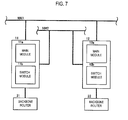
Fig. 7 , when the twobackbone routers wireless management stations wireless management station backbone router - The present invention is devised by paying attention to these problems and it is an object of the present invention to realize a network management system which can suppress to a minimum a time during which it is impossible to make a communication when a trouble occurs in any of field wireless management stations formed to be redundant.
- The object of the present invention is achieved by below-described structures. (1) A network management system in which field wireless management stations having gateway functions and system management functions incorporated are redundantly connected together,
wherein the field wireless management stations include at least switch modules, and
the plurality of field wireless management stations are connected to each other through a synchronizing cable and synchronizing connectors provided in the synchronizing cable, and switches are connected in series to a synchronizing system which connects the switch modules to each other to turn on and off the system. - (2) The network management system according to the above-described (1), wherein backbone routers are redundantly connected to each of the redundantly connected field wireless management stations through layer-2-switches which are connected together in the form of a loop.
- (3) The network management system according to the above-described (1) or (2), wherein the plurality of redundantly connected field wireless management stations are connected so as to be individually identified by the synchronizing cable and the synchronizing connectors.
- (4) The network management system according to any one of the above-described (1) to (3), wherein the synchronizing cable and the synchronizing connectors also include a power wire.
- (5) The network management system according to any one of the above-described (1) to (4), wherein it is detected whether the synchronizing cable and the synchronizing connectors are pulled out from or inserted into at least one of the field wireless management stations in accordance with a function which individually identifies the plurality of redundantly connected field wireless management stations by the synchronizing cable and the synchronizing connectors.
- In the present invention, when the switch provided in the synchronizing system which connects the switch modules to each other is turned on, the backbone routers can be respectively directly connected to the field wireless management stations. When the switch is turned off, the backbone routers can be respectively connected to the field wireless management stations through the layer-2-switches which are connected in the form of a loop.
-
-
Fig. 1 is an explanatory view of a structure showing one exemplary embodiment of the present invention. -
Fig. 2 is enlarged views of groups of signal wires inFig. 1 . -
Fig. 3 is an explanatory view of a redundant connection in the structure shown inFig. 1 . -
Fig. 4 is an explanatory view of a structure showing another exemplary embodiment of the present invention. -
Fig. 5 is an explanatory view of a case when switches SWm are turned on in the structure shown inFig. 1 . -
Fig. 6 is an explanatory view of a structure which shows an example of a conventional redundant connection of a field wireless management station. -
Fig. 7 is an explanatory view of a structure which shows another example of a conventional redundant connection of a field wireless management station. - Now, an exemplary embodiment of a network management system according to the present invention will be described below by using the drawings.
Fig. 1 is an explanatory view of a structure showing one exemplary embodiment of the present invention. Parts common to those shown inFig. 6 are designated by the same reference numerals. - The network management system according to the present exemplary embodiment is a network management system in which field wireless management stations having gateway functions and system management functions incorporated are redundantly connected to each other. As shown in
Fig. 1 , in the fieldwireless management stations pin identifying parts main modules switch modules connectors CN 11 andCN 12 are respectively provided. - Then, a synchronizing
cable 30 is connected to theconnectors CN 11 andCN 12, so that themain modules switch modules wireless management stations cable 30. - Further, since the field
wireless management stations pin identifying parts Fig. 1 , pins of theconnectors CN 11 andCN 12 that are respectively connected to thepin identifying parts - The
main module 11a, theswitch module 11b and thepin identifying part 11c which form the fieldwireless management station 11 are mutually connected together through an inner bus not shown in the drawing. Further, themain module 12a, theswitch module 12b and thepin identifying part 12c which form the fieldwireless management station 12 are also mutually connected together through an inner bus not shown in the drawing. - In one end of the synchronizing
cable 30, a connector CNa is provided which is fitted and connected to theconnector CN 11 of the one fieldwireless management station 11. In the other end, a connector CNb is provided which is fitted and connected to theconnector CN 12 of the other fieldwireless management station 12. - Between the connectors CNa and CNb, are provided a first group of signal wires Pa which connect the
main modules switch module - In the vicinity of the connector CNa, a third group of signal wires Pc1 are provided which identify the one field
wireless management station 11. In the vicinity of the connector CNb, a fourth group of signal wires Pc2 are provided which identify the other fieldwireless management station 12. These connectors CNa and CNb function as synchronizing connectors. - Then, in the
switch modules switch modules - Pb.
- The turning on and off operations of the switches SWm are externally set by a
setting tool 40. In the exemplary embodiment shown inFig. 1 ,backbone routers wireless management stations -
Figs. 2(A) and 2(B) show enlarged views of the groups of signal wires for identifying the fieldwireless management stations Fig. 2(A) shows the third group of signal wires Pc1 andFig. 2(B) shows the fourth group of signal wires Pc2. In the third group of signal wires Pc1 shown inFig. 2(A) , signal wires Pc11 and Pc12 are short-circuit connected to each other. In the fourth group of signal wires Pc2 shown inFig. 2(B) , signal wires Pc21 and Pc23 are connected to each other in a short-circuit state. - Operations of the parts in the structure shown in
Fig. 1 will be respectively described. - The
main modules main modules main modules cable 30 to make equalization of various kinds of information. - Further, the
main modules cable 30 to theconnectors CN 11 andCN 12 respectively through the inner buses not shown in the drawing. - Thus, when a short-circuit state of a prescribed identifying pin cannot be detected, it can be decided that the connectors are not fitted and connected to each other.
- The
switch modules cable 30. The switches SWm are set to off states as mentioned above. -
Fig. 3 is an explanatory view of a redundant connection in the structure shown inFig. 1 . As shown inFig. 3 , thebackbone routers wireless management stations - The
backbone router 21 is connected to the fieldwireless management station 11 through a rout A or D shown inFig. 3 , and connected to the fieldwireless management station 12 through a route B or C. - The above-described symbol A designates the route passing through the layer-2-switches respectively in order of SW4 and SW1.
- The above-described symbol D designates the route passing through the layer-2-switched respectively in order of SW4, SW3, SW2 and SW1.
- The above-described symbol B designates the route passing through the layer-2-switches respectively in order of SW4, SW1 and SW2.
- The above-described symbol C designates the route passing through the layer-2-switches respectively in order of SW4, SW3 and SW2.
- The
backbone router 22 is connected to the fieldwireless management station 12 through a rout E or H shown inFig. 3 , and connected to the fieldwireless management station 11 through a route F or G. - The above-described symbol E designates the route passing through the layer-2-switches respectively in order of SW3 and SW2.
- The above-described symbol H designates the route passing through the layer-2-switches respectively in order of SW3, SW4, SW1 and SW2.
- The above-described symbol F designates the route passing through the layer-2-switches respectively in order of SW3, SW2 and SW1.
- The above-described symbol G designates the route passing through the layer-2-switches respectively in order of SW3, SW4 and SW1.
- When the connector CNa of the synchronizing
cable 30 is fitted and connected to theconnector CN 11, thepin identifying part 11c provided in the fieldwireless management station 11 detects the short-circuit connection of the signal wires Pc11 and Pc12 in the third group of signal wires Pc1 to identify the fieldwireless management station 11, and outputs an identified result to themain module 11a. - When the connector CNb of the synchronizing
cable 30 is fitted and connected to theconnector CN 12, thepin identifying part 12c provided in the fieldwireless management station 12 detects the short-circuit connection of the signal wires Pc21 and Pc23 in the fourth group of signal wires Pc2 to identify the fieldwireless management station 12, and outputs an identified result to themain module 12a. - When the two
backbone routers wireless management stations Fig. 7 , as shown inFig. 4 , the switches SWm are set to on states. - As a result, the
backbone routers wireless management stations - A redundant operation carried out when an abnormality occurs will be described below.
- As a precondition, in order to realize the redundant operation, the
main modules cable 30 so as to make the equalization of information. - Under a state that the switches SWm are turned off as shown in
Fig. 3 , and thebackbone routers wireless management stations - For instance, when the trouble occurs in the cable which connects the layer-2-switch SW1 to the field
wireless management station 11 or the layer-2-switch SW1, the communicativeness to the fieldwireless management station 11 is deteriorated. - Thus, for instance, in the
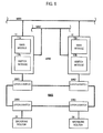
main module 11 a of the fieldwireless management station 11, a unit is provided which monitors connected states respectively of ports of the layer-2-switch SW1 to be connected to the fieldwireless management station 11. When such a trouble as to deteriorate the communicativeness to the fieldwireless management station 11 occurs, as shown inFig. 5 , the switches SWm are turned on to ensure the communicativeness to the fieldwireless management station 11 through the fieldwireless management station 12. - After that, when the disconnection of the cable or the trouble of the layer-2-switch SW1 is fixed by a maintenance or an exchange, the switches SWm are turned off again.
- Thus, a time can be suppressed to a minimum during which it is impossible to make a communication when the trouble occurs in any of the field wireless management stations formed to be redundant.
- When the identifying pins are also included in the connectors CNa and CNb which function as the synchronizing connectors, individual identifiers can be respectively added to the two field
wireless management stations - Further, when the synchronizing connectors are not connected, the field wireless management stations are not allowed to be activated. Thus, a wrong operation due to a mistake in connection can be prevented.
- Further, signals of the synchronizing network and the backbone network which pass through the synchronizing
cable 30 are duplicated, so that reliability can be improved. - Further, the power wire is allowed to pass through the synchronizing cable, so that the power source can be also made to be redundant.
- As described above, according to the present invention, the network management system can be realized which can suppress to a minimum the time during which it is impossible to make a communication when the trouble occurs in any of the field wireless management stations formed to be redundant.
- The above-mentioned description merely shows a specifically preferable exemplary embodiment for the purpose of explanation and exemplification of the present invention. Accordingly, the present invention is not limited to the above-described exemplary embodiment and includes more changes and modifications within a range that does not deviate from an essence thereof.
- This application is based on Japanese Patent Application (No.
2012-147174) filed on June 29, 2012 - 11, 12 ... field
wireless management station main module switch module part CN 11,CN 12 ... connector NW1 ...host network backbone network 30 ... synchronizing cable CNa, CNb ... connector (synchronizing connector) Pa, Pb, Pc1, Pc2 ... group of signal wires Pc11, Pc12, Pc21, Pc 23 ... signal wire SW1 to SW4 ... layer-2-switch SWm... switch
Claims (5)
- A network management system in which field wireless management stations having gateway functions and system management functions incorporated are redundantly connected together,
wherein the field wireless management stations include at least switch modules, and
the plurality of field wireless management stations are connected to each other through a synchronizing cable and synchronizing connectors provided in the synchronizing cable, and switches are connected in series to a synchronizing system which connects the switch modules to each other to turn on and off the system. - The network management system according to claim 1, wherein backbone routers are redundantly connected to each of the redundantly connected field wireless management stations through layer-2-switches which are connected together in the form of a loop.
- The network management system according to claim 1 or claim 2, wherein the plurality of redundantly connected field wireless management stations are connected so as to be individually identified by the synchronizing cable and the synchronizing connectors.
- The network management system according to any one of claims 1 to 3, wherein the synchronizing cable and the synchronizing connectors also include a power wire.
- The network management system according to any one of claims 1 to 4, wherein it is detected whether the synchronizing cable and the synchronizing connectors are pulled out from or inserted into at least one of the field wireless management stations in accordance with a function which individually identifies the plurality of redundantly connected field wireless management stations by the synchronizing cable and the synchronizing connectors.
Applications Claiming Priority (2)
| Application Number | Priority Date | Filing Date | Title |
|---|---|---|---|
| JP2012147174A JP5556858B2 (en) | 2012-06-29 | 2012-06-29 | Network management system |
| PCT/JP2013/067037 WO2014002880A1 (en) | 2012-06-29 | 2013-06-21 | Network management system |
Publications (3)
| Publication Number | Publication Date |
|---|---|
| EP2869498A1 true EP2869498A1 (en) | 2015-05-06 |
| EP2869498A4 EP2869498A4 (en) | 2016-03-02 |
| EP2869498B1 EP2869498B1 (en) | 2020-12-16 |
Family
ID=49783037
Family Applications (1)
| Application Number | Title | Priority Date | Filing Date |
|---|---|---|---|
| EP13810727.1A Active EP2869498B1 (en) | 2012-06-29 | 2013-06-21 | Network management system |
Country Status (5)
| Country | Link |
|---|---|
| US (1) | US9503312B2 (en) |
| EP (1) | EP2869498B1 (en) |
| JP (1) | JP5556858B2 (en) |
| CN (1) | CN103765830B (en) |
| WO (1) | WO2014002880A1 (en) |
Families Citing this family (1)
| Publication number | Priority date | Publication date | Assignee | Title |
|---|---|---|---|---|
| JP6304172B2 (en) * | 2015-08-14 | 2018-04-04 | 横河電機株式会社 | Diagnostic method, ID module and process control system |
Family Cites Families (20)
| Publication number | Priority date | Publication date | Assignee | Title |
|---|---|---|---|---|
| JPH10285202A (en) | 1997-03-31 | 1998-10-23 | Mitsubishi Heavy Ind Ltd | Method for controlling communication of duplexed gateway |
| WO1999033278A2 (en) * | 1997-09-26 | 1999-07-01 | Alcatel Usa Sourcing Lp | Interface components for a telecommunications switching platform |
| JP2001118639A (en) * | 1999-10-18 | 2001-04-27 | Murata Mach Ltd | Incorrect connection detecting device for connector |
| US7203907B2 (en) * | 2002-02-07 | 2007-04-10 | Sap Aktiengesellschaft | Multi-modal synchronization |
| US20060015586A1 (en) | 2004-06-04 | 2006-01-19 | Manish Sharma | Simplifying connection establishment in systems accessing other systems via redundant addressable gateways |
| JP2006310928A (en) | 2005-04-26 | 2006-11-09 | Yokogawa Electric Corp | Gateway system |
| US7573282B2 (en) | 2006-04-26 | 2009-08-11 | Hewlett-Packard Development Company, L.P. | Ball grid array connection monitoring system and method |
| US7848268B2 (en) * | 2006-11-27 | 2010-12-07 | Honeywell International Inc. | Fault tolerance in wireless networks |
| US20090316706A1 (en) | 2008-06-18 | 2009-12-24 | Telect, Inc. | Structured premise networking system |
| CN102124700B (en) * | 2008-06-18 | 2014-04-09 | 爱默生过程管理电力和水力解决方案有限公司 | Systems and methods for wireless process communication over a differentiated network |
| JP5293141B2 (en) * | 2008-12-16 | 2013-09-18 | 日本電気株式会社 | Redundant system |
| US20110161538A1 (en) | 2009-12-31 | 2011-06-30 | Schneider Electric USA, Inc. | Method and System for Implementing Redundant Network Interface Modules in a Distributed I/O System |
| WO2012012723A2 (en) * | 2010-07-23 | 2012-01-26 | Saudi Arabian Oil Company | Machines, computer program products, and computer-implemented methods providing an integrated node for data acquisition and control |
| FR2963451B1 (en) * | 2010-07-27 | 2012-12-07 | St Microelectronics Rousset | AUTHENTICATION OF MULTIPROTOCOL COMMUNICATION |
| JP5120672B2 (en) * | 2010-09-03 | 2013-01-16 | 横河電機株式会社 | Wireless network path setting device |
| EP2734898A1 (en) * | 2011-07-20 | 2014-05-28 | General Equipment And Manufacturing Company, Inc. | Wireless monitoring and control of safety stations in a process plant |
| US9804647B2 (en) * | 2012-01-06 | 2017-10-31 | Fisher Controls International Llc | Continuously powered field device |
| EP2732664B1 (en) * | 2012-06-06 | 2016-03-16 | Unify GmbH & Co. KG | Method of operating a communication device operable in an active mode and in an idle mode and the communication device operable in an active mode and in an idle mode |
| JP5445626B2 (en) * | 2012-06-25 | 2014-03-19 | 横河電機株式会社 | Network management system |
| JP5601353B2 (en) * | 2012-06-29 | 2014-10-08 | 横河電機株式会社 | Network management system |
-
2012
- 2012-06-29 JP JP2012147174A patent/JP5556858B2/en active Active
-
2013
- 2013-06-21 US US14/343,160 patent/US9503312B2/en active Active
- 2013-06-21 EP EP13810727.1A patent/EP2869498B1/en active Active
- 2013-06-21 WO PCT/JP2013/067037 patent/WO2014002880A1/en not_active Ceased
- 2013-06-21 CN CN201380002891.8A patent/CN103765830B/en active Active
Also Published As
| Publication number | Publication date |
|---|---|
| JP2014011641A (en) | 2014-01-20 |
| EP2869498B1 (en) | 2020-12-16 |
| US20140233371A1 (en) | 2014-08-21 |
| EP2869498A4 (en) | 2016-03-02 |
| CN103765830A (en) | 2014-04-30 |
| JP5556858B2 (en) | 2014-07-23 |
| CN103765830B (en) | 2018-05-25 |
| WO2014002880A1 (en) | 2014-01-03 |
| US9503312B2 (en) | 2016-11-22 |
Similar Documents
| Publication | Publication Date | Title |
|---|---|---|
| CN101160837B (en) | Data path switching device, multiport switching device, communication network and corresponding method | |
| JP5021037B2 (en) | Communication system having master / slave structure | |
| CN100524124C (en) | Redundant supervisory control system, and redundancy switching method of the same | |
| JP4732865B2 (en) | Method and apparatus for operating a network | |
| JP2020194790A (en) | Industrial control system cable | |
| CN100588169C (en) | User, master unit, communication system and method of operation thereof | |
| US8559300B2 (en) | Redundant communications network | |
| EP2869497B1 (en) | Network management system | |
| CN101192056A (en) | Safety module and automation system | |
| US20230259098A1 (en) | Apparatus and Method for Controlling a Safety-Critical Process | |
| EP4024142B1 (en) | Multiple network redundancy protocols for data flow using the same physical interface | |
| US7844865B2 (en) | Bus module for connection to a bus system and use of such a bus module in an AS-i bus system | |
| EP2067313B1 (en) | Routing facility for a subsea electronics module | |
| EP2869498B1 (en) | Network management system | |
| US20090116405A1 (en) | Redundant Automation Data Communications Network | |
| US12579092B2 (en) | Apparatus for connecting a field device to a control system | |
| KR20050029674A (en) | Redundant network apparatus for monitoring and controling of industrial system | |
| JP2008520135A (en) | Parallel flushing of processing units by network reconfiguration | |
| US20250055837A1 (en) | Security apparatus, management apparatus, communication system, and security management method | |
| US12184435B2 (en) | On-machine industrial SPE network system and method | |
| JPH02143750A (en) | Transmission line branching device | |
| US20130091314A1 (en) | Field Bus Network Adapter and Field Bus Network Subscriber with Field Bus Connections | |
| JPH02250538A (en) | Multiplex transmission network communication system | |
| CN118400226A (en) | Dual-ring network control system and communication control method thereof | |
| JP2016164736A (en) | Supervisory control system |
Legal Events
| Date | Code | Title | Description |
|---|---|---|---|
| PUAI | Public reference made under article 153(3) epc to a published international application that has entered the european phase |
Free format text: ORIGINAL CODE: 0009012 |
|
| 17P | Request for examination filed |
Effective date: 20140306 |
|
| AK | Designated contracting states |
Kind code of ref document: A1 Designated state(s): AL AT BE BG CH CY CZ DE DK EE ES FI FR GB GR HR HU IE IS IT LI LT LU LV MC MK MT NL NO PL PT RO RS SE SI SK SM TR |
|
| AX | Request for extension of the european patent |
Extension state: BA ME |
|
| DAX | Request for extension of the european patent (deleted) | ||
| RA4 | Supplementary search report drawn up and despatched (corrected) |
Effective date: 20160128 |
|
| RIC1 | Information provided on ipc code assigned before grant |
Ipc: H04W 24/02 20090101ALI20160122BHEP Ipc: H04W 4/04 20090101ALI20160122BHEP Ipc: H04L 12/28 20060101AFI20160122BHEP |
|
| STAA | Information on the status of an ep patent application or granted ep patent |
Free format text: STATUS: EXAMINATION IS IN PROGRESS |
|
| 17Q | First examination report despatched |
Effective date: 20190807 |
|
| REG | Reference to a national code |
Ref country code: DE Ref legal event code: R079 Ref document number: 602013074769 Country of ref document: DE Free format text: PREVIOUS MAIN CLASS: H04L0012280000 Ipc: H04L0012400000 |
|
| GRAP | Despatch of communication of intention to grant a patent |
Free format text: ORIGINAL CODE: EPIDOSNIGR1 |
|
| STAA | Information on the status of an ep patent application or granted ep patent |
Free format text: STATUS: GRANT OF PATENT IS INTENDED |
|
| RIC1 | Information provided on ipc code assigned before grant |
Ipc: H04W 24/04 20090101ALI20200602BHEP Ipc: H04L 12/40 20060101AFI20200602BHEP Ipc: H04L 12/46 20060101ALI20200602BHEP |
|
| INTG | Intention to grant announced |
Effective date: 20200707 |
|
| GRAS | Grant fee paid |
Free format text: ORIGINAL CODE: EPIDOSNIGR3 |
|
| GRAA | (expected) grant |
Free format text: ORIGINAL CODE: 0009210 |
|
| STAA | Information on the status of an ep patent application or granted ep patent |
Free format text: STATUS: THE PATENT HAS BEEN GRANTED |
|
| AK | Designated contracting states |
Kind code of ref document: B1 Designated state(s): AL AT BE BG CH CY CZ DE DK EE ES FI FR GB GR HR HU IE IS IT LI LT LU LV MC MK MT NL NO PL PT RO RS SE SI SK SM TR |
|
| REG | Reference to a national code |
Ref country code: GB Ref legal event code: FG4D |
|
| REG | Reference to a national code |
Ref country code: DE Ref legal event code: R096 Ref document number: 602013074769 Country of ref document: DE |
|
| REG | Reference to a national code |
Ref country code: IE Ref legal event code: FG4D |
|
| REG | Reference to a national code |
Ref country code: AT Ref legal event code: REF Ref document number: 1346596 Country of ref document: AT Kind code of ref document: T Effective date: 20210115 |
|
| REG | Reference to a national code |
Ref country code: NL Ref legal event code: FP |
|
| PG25 | Lapsed in a contracting state [announced via postgrant information from national office to epo] |
Ref country code: RS Free format text: LAPSE BECAUSE OF FAILURE TO SUBMIT A TRANSLATION OF THE DESCRIPTION OR TO PAY THE FEE WITHIN THE PRESCRIBED TIME-LIMIT Effective date: 20201216 Ref country code: FI Free format text: LAPSE BECAUSE OF FAILURE TO SUBMIT A TRANSLATION OF THE DESCRIPTION OR TO PAY THE FEE WITHIN THE PRESCRIBED TIME-LIMIT Effective date: 20201216 Ref country code: NO Free format text: LAPSE BECAUSE OF FAILURE TO SUBMIT A TRANSLATION OF THE DESCRIPTION OR TO PAY THE FEE WITHIN THE PRESCRIBED TIME-LIMIT Effective date: 20210316 Ref country code: GR Free format text: LAPSE BECAUSE OF FAILURE TO SUBMIT A TRANSLATION OF THE DESCRIPTION OR TO PAY THE FEE WITHIN THE PRESCRIBED TIME-LIMIT Effective date: 20210317 |
|
| REG | Reference to a national code |
Ref country code: AT Ref legal event code: MK05 Ref document number: 1346596 Country of ref document: AT Kind code of ref document: T Effective date: 20201216 |
|
| PG25 | Lapsed in a contracting state [announced via postgrant information from national office to epo] |
Ref country code: BG Free format text: LAPSE BECAUSE OF FAILURE TO SUBMIT A TRANSLATION OF THE DESCRIPTION OR TO PAY THE FEE WITHIN THE PRESCRIBED TIME-LIMIT Effective date: 20210316 Ref country code: LV Free format text: LAPSE BECAUSE OF FAILURE TO SUBMIT A TRANSLATION OF THE DESCRIPTION OR TO PAY THE FEE WITHIN THE PRESCRIBED TIME-LIMIT Effective date: 20201216 Ref country code: SE Free format text: LAPSE BECAUSE OF FAILURE TO SUBMIT A TRANSLATION OF THE DESCRIPTION OR TO PAY THE FEE WITHIN THE PRESCRIBED TIME-LIMIT Effective date: 20201216 |
|
| PG25 | Lapsed in a contracting state [announced via postgrant information from national office to epo] |
Ref country code: HR Free format text: LAPSE BECAUSE OF FAILURE TO SUBMIT A TRANSLATION OF THE DESCRIPTION OR TO PAY THE FEE WITHIN THE PRESCRIBED TIME-LIMIT Effective date: 20201216 |
|
| REG | Reference to a national code |
Ref country code: LT Ref legal event code: MG9D |
|
| PG25 | Lapsed in a contracting state [announced via postgrant information from national office to epo] |
Ref country code: SK Free format text: LAPSE BECAUSE OF FAILURE TO SUBMIT A TRANSLATION OF THE DESCRIPTION OR TO PAY THE FEE WITHIN THE PRESCRIBED TIME-LIMIT Effective date: 20201216 Ref country code: RO Free format text: LAPSE BECAUSE OF FAILURE TO SUBMIT A TRANSLATION OF THE DESCRIPTION OR TO PAY THE FEE WITHIN THE PRESCRIBED TIME-LIMIT Effective date: 20201216 Ref country code: PT Free format text: LAPSE BECAUSE OF FAILURE TO SUBMIT A TRANSLATION OF THE DESCRIPTION OR TO PAY THE FEE WITHIN THE PRESCRIBED TIME-LIMIT Effective date: 20210416 Ref country code: LT Free format text: LAPSE BECAUSE OF FAILURE TO SUBMIT A TRANSLATION OF THE DESCRIPTION OR TO PAY THE FEE WITHIN THE PRESCRIBED TIME-LIMIT Effective date: 20201216 Ref country code: CZ Free format text: LAPSE BECAUSE OF FAILURE TO SUBMIT A TRANSLATION OF THE DESCRIPTION OR TO PAY THE FEE WITHIN THE PRESCRIBED TIME-LIMIT Effective date: 20201216 Ref country code: EE Free format text: LAPSE BECAUSE OF FAILURE TO SUBMIT A TRANSLATION OF THE DESCRIPTION OR TO PAY THE FEE WITHIN THE PRESCRIBED TIME-LIMIT Effective date: 20201216 Ref country code: SM Free format text: LAPSE BECAUSE OF FAILURE TO SUBMIT A TRANSLATION OF THE DESCRIPTION OR TO PAY THE FEE WITHIN THE PRESCRIBED TIME-LIMIT Effective date: 20201216 |
|
| PG25 | Lapsed in a contracting state [announced via postgrant information from national office to epo] |
Ref country code: AT Free format text: LAPSE BECAUSE OF FAILURE TO SUBMIT A TRANSLATION OF THE DESCRIPTION OR TO PAY THE FEE WITHIN THE PRESCRIBED TIME-LIMIT Effective date: 20201216 Ref country code: PL Free format text: LAPSE BECAUSE OF FAILURE TO SUBMIT A TRANSLATION OF THE DESCRIPTION OR TO PAY THE FEE WITHIN THE PRESCRIBED TIME-LIMIT Effective date: 20201216 |
|
| REG | Reference to a national code |
Ref country code: DE Ref legal event code: R097 Ref document number: 602013074769 Country of ref document: DE |
|
| PG25 | Lapsed in a contracting state [announced via postgrant information from national office to epo] |
Ref country code: IS Free format text: LAPSE BECAUSE OF FAILURE TO SUBMIT A TRANSLATION OF THE DESCRIPTION OR TO PAY THE FEE WITHIN THE PRESCRIBED TIME-LIMIT Effective date: 20210416 |
|
| PLBE | No opposition filed within time limit |
Free format text: ORIGINAL CODE: 0009261 |
|
| STAA | Information on the status of an ep patent application or granted ep patent |
Free format text: STATUS: NO OPPOSITION FILED WITHIN TIME LIMIT |
|
| PG25 | Lapsed in a contracting state [announced via postgrant information from national office to epo] |
Ref country code: AL Free format text: LAPSE BECAUSE OF FAILURE TO SUBMIT A TRANSLATION OF THE DESCRIPTION OR TO PAY THE FEE WITHIN THE PRESCRIBED TIME-LIMIT Effective date: 20201216 Ref country code: IT Free format text: LAPSE BECAUSE OF FAILURE TO SUBMIT A TRANSLATION OF THE DESCRIPTION OR TO PAY THE FEE WITHIN THE PRESCRIBED TIME-LIMIT Effective date: 20201216 |
|
| 26N | No opposition filed |
Effective date: 20210917 |
|
| PG25 | Lapsed in a contracting state [announced via postgrant information from national office to epo] |
Ref country code: ES Free format text: LAPSE BECAUSE OF FAILURE TO SUBMIT A TRANSLATION OF THE DESCRIPTION OR TO PAY THE FEE WITHIN THE PRESCRIBED TIME-LIMIT Effective date: 20201216 Ref country code: DK Free format text: LAPSE BECAUSE OF FAILURE TO SUBMIT A TRANSLATION OF THE DESCRIPTION OR TO PAY THE FEE WITHIN THE PRESCRIBED TIME-LIMIT Effective date: 20201216 |
|
| PG25 | Lapsed in a contracting state [announced via postgrant information from national office to epo] |
Ref country code: MC Free format text: LAPSE BECAUSE OF FAILURE TO SUBMIT A TRANSLATION OF THE DESCRIPTION OR TO PAY THE FEE WITHIN THE PRESCRIBED TIME-LIMIT Effective date: 20201216 |
|
| REG | Reference to a national code |
Ref country code: CH Ref legal event code: PL |
|
| PG25 | Lapsed in a contracting state [announced via postgrant information from national office to epo] |
Ref country code: SI Free format text: LAPSE BECAUSE OF FAILURE TO SUBMIT A TRANSLATION OF THE DESCRIPTION OR TO PAY THE FEE WITHIN THE PRESCRIBED TIME-LIMIT Effective date: 20201216 |
|
| REG | Reference to a national code |
Ref country code: BE Ref legal event code: MM Effective date: 20210630 |
|
| PG25 | Lapsed in a contracting state [announced via postgrant information from national office to epo] |
Ref country code: LU Free format text: LAPSE BECAUSE OF NON-PAYMENT OF DUE FEES Effective date: 20210621 |
|
| PG25 | Lapsed in a contracting state [announced via postgrant information from national office to epo] |
Ref country code: LI Free format text: LAPSE BECAUSE OF NON-PAYMENT OF DUE FEES Effective date: 20210630 Ref country code: IE Free format text: LAPSE BECAUSE OF NON-PAYMENT OF DUE FEES Effective date: 20210621 Ref country code: CH Free format text: LAPSE BECAUSE OF NON-PAYMENT OF DUE FEES Effective date: 20210630 |
|
| PG25 | Lapsed in a contracting state [announced via postgrant information from national office to epo] |
Ref country code: IS Free format text: LAPSE BECAUSE OF FAILURE TO SUBMIT A TRANSLATION OF THE DESCRIPTION OR TO PAY THE FEE WITHIN THE PRESCRIBED TIME-LIMIT Effective date: 20210416 |
|
| PG25 | Lapsed in a contracting state [announced via postgrant information from national office to epo] |
Ref country code: BE Free format text: LAPSE BECAUSE OF NON-PAYMENT OF DUE FEES Effective date: 20210630 |
|
| PG25 | Lapsed in a contracting state [announced via postgrant information from national office to epo] |
Ref country code: HU Free format text: LAPSE BECAUSE OF FAILURE TO SUBMIT A TRANSLATION OF THE DESCRIPTION OR TO PAY THE FEE WITHIN THE PRESCRIBED TIME-LIMIT; INVALID AB INITIO Effective date: 20130621 |
|
| PG25 | Lapsed in a contracting state [announced via postgrant information from national office to epo] |
Ref country code: CY Free format text: LAPSE BECAUSE OF FAILURE TO SUBMIT A TRANSLATION OF THE DESCRIPTION OR TO PAY THE FEE WITHIN THE PRESCRIBED TIME-LIMIT Effective date: 20201216 |
|
| P01 | Opt-out of the competence of the unified patent court (upc) registered |
Effective date: 20230603 |
|
| PGFP | Annual fee paid to national office [announced via postgrant information from national office to epo] |
Ref country code: NL Payment date: 20230515 Year of fee payment: 11 Ref country code: FR Payment date: 20230510 Year of fee payment: 11 |
|
| PGFP | Annual fee paid to national office [announced via postgrant information from national office to epo] |
Ref country code: GB Payment date: 20230427 Year of fee payment: 11 |
|
| PG25 | Lapsed in a contracting state [announced via postgrant information from national office to epo] |
Ref country code: MK Free format text: LAPSE BECAUSE OF FAILURE TO SUBMIT A TRANSLATION OF THE DESCRIPTION OR TO PAY THE FEE WITHIN THE PRESCRIBED TIME-LIMIT Effective date: 20201216 |
|
| PG25 | Lapsed in a contracting state [announced via postgrant information from national office to epo] |
Ref country code: TR Free format text: LAPSE BECAUSE OF FAILURE TO SUBMIT A TRANSLATION OF THE DESCRIPTION OR TO PAY THE FEE WITHIN THE PRESCRIBED TIME-LIMIT Effective date: 20201216 |
|
| PG25 | Lapsed in a contracting state [announced via postgrant information from national office to epo] |
Ref country code: MT Free format text: LAPSE BECAUSE OF FAILURE TO SUBMIT A TRANSLATION OF THE DESCRIPTION OR TO PAY THE FEE WITHIN THE PRESCRIBED TIME-LIMIT Effective date: 20201216 |
|
| REG | Reference to a national code |
Ref country code: NL Ref legal event code: MM Effective date: 20240701 |
|
| GBPC | Gb: european patent ceased through non-payment of renewal fee |
Effective date: 20240621 |
|
| PG25 | Lapsed in a contracting state [announced via postgrant information from national office to epo] |
Ref country code: NL Free format text: LAPSE BECAUSE OF NON-PAYMENT OF DUE FEES Effective date: 20240701 |
|
| PG25 | Lapsed in a contracting state [announced via postgrant information from national office to epo] |
Ref country code: NL Free format text: LAPSE BECAUSE OF NON-PAYMENT OF DUE FEES Effective date: 20240701 |
|
| PG25 | Lapsed in a contracting state [announced via postgrant information from national office to epo] |
Ref country code: FR Free format text: LAPSE BECAUSE OF NON-PAYMENT OF DUE FEES Effective date: 20240630 |
|
| PG25 | Lapsed in a contracting state [announced via postgrant information from national office to epo] |
Ref country code: GB Free format text: LAPSE BECAUSE OF NON-PAYMENT OF DUE FEES Effective date: 20240621 |
|
| PGFP | Annual fee paid to national office [announced via postgrant information from national office to epo] |
Ref country code: DE Payment date: 20250520 Year of fee payment: 13 |