EP2869495B1 - Node de-duplication in a network monitoring system - Google Patents
Node de-duplication in a network monitoring system Download PDFInfo
- Publication number
- EP2869495B1 EP2869495B1 EP14191409.3A EP14191409A EP2869495B1 EP 2869495 B1 EP2869495 B1 EP 2869495B1 EP 14191409 A EP14191409 A EP 14191409A EP 2869495 B1 EP2869495 B1 EP 2869495B1
- Authority
- EP
- European Patent Office
- Prior art keywords
- nodes
- duplicate
- discovered
- node
- addresses
- Prior art date
- Legal status (The legal status is an assumption and is not a legal conclusion. Google has not performed a legal analysis and makes no representation as to the accuracy of the status listed.)
- Active
Links
Images




Classifications
-
- H—ELECTRICITY
- H04—ELECTRIC COMMUNICATION TECHNIQUE
- H04L—TRANSMISSION OF DIGITAL INFORMATION, e.g. TELEGRAPHIC COMMUNICATION
- H04L41/00—Arrangements for maintenance, administration or management of data switching networks, e.g. of packet switching networks
- H04L41/08—Configuration management of networks or network elements
- H04L41/0866—Checking the configuration
-
- H—ELECTRICITY
- H04—ELECTRIC COMMUNICATION TECHNIQUE
- H04L—TRANSMISSION OF DIGITAL INFORMATION, e.g. TELEGRAPHIC COMMUNICATION
- H04L41/00—Arrangements for maintenance, administration or management of data switching networks, e.g. of packet switching networks
- H04L41/08—Configuration management of networks or network elements
- H04L41/085—Retrieval of network configuration; Tracking network configuration history
- H04L41/0853—Retrieval of network configuration; Tracking network configuration history by actively collecting configuration information or by backing up configuration information
-
- H—ELECTRICITY
- H04—ELECTRIC COMMUNICATION TECHNIQUE
- H04L—TRANSMISSION OF DIGITAL INFORMATION, e.g. TELEGRAPHIC COMMUNICATION
- H04L41/00—Arrangements for maintenance, administration or management of data switching networks, e.g. of packet switching networks
- H04L41/08—Configuration management of networks or network elements
- H04L41/0866—Checking the configuration
- H04L41/0873—Checking configuration conflicts between network elements
-
- H—ELECTRICITY
- H04—ELECTRIC COMMUNICATION TECHNIQUE
- H04L—TRANSMISSION OF DIGITAL INFORMATION, e.g. TELEGRAPHIC COMMUNICATION
- H04L61/00—Network arrangements, protocols or services for addressing or naming
- H04L61/45—Network directories; Name-to-address mapping
- H04L61/4541—Directories for service discovery
Definitions
- Embodiments of the invention generally relate to network traffic monitoring, analysis, and/or reporting. More particularly, some embodiments are directed to methods, systems, and computer programs for node de-duplication of physical nodes monitored by a network monitoring system, for example.
- Network management includes activities, methods, procedures, and tools related to the operation, administration, maintenance, and/or provisioning of networked systems. Functions that can be performed as part of network management may include, for example, planning, controlling, deploying, allocating, coordinating, and monitoring the resources of a network. Further functions may be related to network planning, frequency allocation, load balancing, configuration management, fault management, security management, performance management, bandwidth management, route analytics, and accounting management.
- Network traffic data is of interest to network administrators for a number of reasons, including analyzing the impact of a new application on the network, troubleshooting network pain points, detecting slow or failing network devices, detecting heavy users of bandwidth, and securing networks.
- Various protocols for network traffic flow data have been developed. These protocols can contain numerous types of information, such as source internet protocol (IP) address, destination IP address, source port, destination port, IP protocol, ingress interface, IP Type of Service, start and finish times, number of bytes, and next hop.
- IP internet protocol
- Certain embodiments are directed to methods, apparatuses, and computer program products for node de-duplication, which comprise, are configured to execute, and are configured to control a processor to execute a process comprising: discovering, by a network monitoring apparatus, nodes in a network, collecting a list of internet protocol (IP) addresses, media access control (MAC) addresses, domain name system (DNS) names, and sysnames for each of the nodes discovered in the network, comparing the IP addresses of each of the discovered nodes with IP addresses of current (monitored) nodes and other (previously) discovered nodes, comparing the MAC addresses of each of the discovered nodes with MAC addresses of the current (monitored) nodes and the other (previously) discovered nodes, comparing the DNS names of each of the discovered nodes with DNS names of the current (monitored) nodes and the other (previously) discovered nodes, comparing the sysnames of each of the discovered nodes with sysnames of the current (monitored) no
- network devices and network nodes may be used interchangeably to refer to any physical device that is capable of connecting to and/or communicating on a network.
- Examples of such devices or nodes may include, but is not limited to, routers, switches, servers, computers, laptops, tablets, telephones, printers, mobile devices, and any other current or future component capable of sending, receiving, or forwarding information over a communications channel.
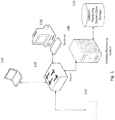
- Fig. 1 illustrates an example of a system according to one embodiment.
- the system includes network monitoring system 100, network monitoring system storage 110, switch device 130, and one or more network devices 120.
- Network monitoring system storage 110 can store network monitoring data.
- Network monitoring system storage 110 can be a database or any other appropriate storage device.
- Network devices 120 may be nodes in the network that are monitored by network traffic monitor 100. It should be noted that any number and type of network devices 120 can be supported in the system. Accordingly, embodiments are not limited to the number and type of network devices illustrated in Fig. 1 .
- network monitoring system storage 110 may store discovery result database tables that store and organize information about discovered network devices in the network.
- network devices can be accessible on multiple internet protocol (IP) addresses. For example, some devices can simultaneously have more than one IP address. Also, some nodes are dynamic in that they have IP addresses that vary in time. Such dynamic IP addresses cause problems for de-duplication logic because it might be matching an outdated primary IP address from discovery result with the current IP address of a dynamic node.
- IP internet protocol
- Embodiments of the invention implement an automatic network discovery that is able to detect such situation and avoid processing the same physical node multiple times (e.g., each time using a different IP address).
- One embodiment includes a de-duplication logic configured to automatically identify duplicate nodes such that a single node is not monitored multiple times.
- Certain embodiments identify one or more pieces of information that function as a node identifier needed to uniquely identify the network node. Having this unique node identifier, certain embodiments can proceed with defining logic, which detects duplicates within nodes found during the discovery process (e.g., same physical network node under different IP addresses) and/or within nodes already being monitored under a different IP address.
- the information used to uniquely identify nodes includes information which can be polled easily, is available for a majority of devices (i.e., vendor independent), is available for Internet Control Message Protocol (ICMP) nodes as well as other types of nodes (e.g., ICMP nodes can be considered to be nodes not reachable over SNMP or WMI), and is a minimal set of information that can still provide accurate results while being efficient.
- ICMP Internet Control Message Protocol
- Certain embodiments can handle at least two typical uses cases.
- one use case may include running an automated network discovery over a subnetwork, which contains devices accessible on multiple IP addresses. As is known, devices that belong to a subnet are addressed with a common, identical, most-significant bit-group in their IP address.
- Another use case may include running an automated network discovery over a subnetwork, which is already being monitored.
- Certain embodiments are able to identify network nodes as network duplicates, even if one set of information was collected in a different time frame than the other. For instance, this may occur when a user decides to import discovery results for a scheduled discovery profile. In such a case, some embodiments may need to work with possibly outdated information collected during discovery and compare it to new information, which is being continuously collected for all monitored nodes. Accordingly, de-duplication according to certain embodiments can take place during a discovery job where discovered nodes are compared to each other such that duplicates are removed, and/or can take place during a discovery result importing where discovered nodes are imported and compared against existing nodes (e.g., nodes stored in network monitoring system storage or database) such that duplicate nodes are identified and removed.
- existing nodes e.g., nodes stored in network monitoring system storage or database
- a data collection set made up of DNS name, Sysname, IP address, and MAC address for each network node is used to help identify duplicate nodes.
- One embodiment includes logic which compares pieces of information from the data collection set against each other, for example DNS to DNS, MACs to MACs, etc.
- the logic may be implemented in a Duplicate Detector component.
- a result from the detection is the match index, which indicates whether there is a match, no match, or unkown..
- Certain embodiments also provide logic for aggregating partial results from detectors and calculating a final verdict as to whether a node is a duplicate or not.
- the node de-duplication may include several sub-iterations that are each responsible for discovering selected IP-range.
- de-duplication is performed to omit nodes (e.g., endpoints) as soon as they are thought to be duplicates.
- nodes e.g., endpoints
- the node is passed to the next step or iteration for processing.
- two sets of duplicate detectors may be provided.
- One set of detectors can be used during the automated discovery process to filter out newly found devices and remove duplicates.
- Another set of detectors can be used during discovery result import to avoid adding duplicate nodes into set of monitored nodes.
- the system is configured to collect list of all DNS names, Sysnames, IP addresses, and MAC addresses for all discovered nodes, and to store them, for example, as part of a discovery job result.
- This information may be stored in the network system monitoring storage or database 110.
- this information can be used during at least two phases of discovery.
- the DNS names, Sysnames, IP addresses, and MAC addresses can be used when running discovery to check whether currently discovered node(s) are a duplicate of any other already found, and/or can be used during discovery result importing to compare discovery result(s) with existing nodes monitored by the system.
- the MAC information is stored to a persistent storage, for example, as part of discovery result.
- Fig. 2 illustrates a system 200, according to one embodiment, which may include an IP address duplicate detector 201, a DNS duplicate detector 203, a MAC address duplicate detector 202, and a Sysname duplicate detector 204.
- a database 210 may be in communication with the IP address duplicate detector 201, DNS duplicate detector 203, MAC address duplicate detector 202, and Sysname duplicate detector 204 such that each of the detectors can collect the relevant addresses stored in the database 210.
- the database 210 may be stored in the network traffic data storage 110 illustrated in Fig. 1 . It should be noted that system 200 can be implemented completely in hardware, or in a combination of hardware and software.
- Each of the duplicate detectors 201, 202, 203, 204 may have a defined priority of order of execution (e.g., lower number indicates earlier execution), a weight which indicates the reliability of the result provided by the duplicate detector (e.g., a weight of 0 will have no impact on final result), and a veto that is used as a top priority to determine if a node is a duplicate or not.
- a defined priority of order of execution e.g., lower number indicates earlier execution
- a weight which indicates the reliability of the result provided by the duplicate detector e.g., a weight of 0 will have no impact on final result
- a veto that is used as a top priority to determine if a node is a duplicate or not.
- DNS duplicate detector 203 may be configured to compare a DNS of a discovered node with all other discovered nodes and current nodes being monitored. In an embodiment, DNS duplicate detector 203 may conclude that a node is a duplicate if the DNS of a discovered node is the same as a DNS used by any of the monitored nodes or any of the other discovered nodes.
- MAC addresses are generally unique by design (although there are situations where the same MAC address is used on two different devices, for example cloned virtual machines hosted in two separated virtual hosts).
- MAC address duplicate detector 202 may be configured to compare a MAC address of a discovered node against all previously collected MAC addresses of nodes, which may be stored in a NodeMACAddresses database table in database 210.
- MAC address duplicate detector 202 may be configured to conclude that a node is a duplicate if a set of discovered MAC addresses is a sub-set of currently monitored MAC addresses for a node or if a set of monitored MAC addresses is sub-set of discovered MAC addresses.
- Table 1 illustrates an example where the nodes are considered equal according to the MAC address duplicate detector 202, where A,B,C,... represent MAC addresses. Meanwhile, Table 2 below illustrates an example where the nodes are not considered equal (e.g., based on MAC addresses).
- Node A and Node B are equal when and only when Node A ' s list of MAC addresses is subset of Node B' s list of MAC addresses or Node B 's list of MACs is subset of Node A 's list of MAC.In that case, the system may look to a different duplicate detector or different de-duplication method (e.g., sysname matching) since, according to MAC addresses, the two nodes are equal.
- a different duplicate detector or different de-duplication method e.g., sysname matching
- Sysname duplicate detector 204 may be configured to compare a sysname of a discovered node with all other discovered nodes and current nodes being monitored. In an embodiment, Sysname duplicate detector 204 may conclude that a node is a duplicate if the Sysname of a discovered node is the same as a Sysname used by any of the monitored nodes or any of the other discovered nodes. In an embodiment, the Sysname may be the Sysname for Simple Network Management Protocol (SNMP) nodes or may be the full computer name for window management instrumentation (WMI) nodes, for example. It should be noted that embodiments do not limit data sources to SNMP and/or WMI, and other types of data sources are equally applicable according to certain embodiments (e.g., CLI over SSH on routers/switches or telnet, etc.).
- SNMP Simple Network Management Protocol
- WMI window management instrumentation
- each duplicate detector may load an associated weight from a settings database table.
- the weight represents the reliability of the result provided by the associated duplicate detector. It is possible to set the weight to -1 to disable the associated duplicate detector.
- weight values may range from 0 to 100 where 0 represents the least reliable and 100 represents the most reliable.
- All of the duplicate detectors (d 1 , ..., d n ) may be executed sequentially with order defined by priority, as discussed above.
- Each of the duplicate detectors may set an 'IsAuthoritative' flag to be true, which may then terminate execution of following duplicate detectors. In such a case, the vote of the duplicate detector with the 'IsAuthoritative' flag set to true is considered as final, ignoring all other votes.
- Priority where d 1 is a first duplicate detector, d 2 is a second duplicate detector, ...and d n is an n th duplicate detector. Accordingly, d n .IsDuplicate() is a function representing the nth duplicate detector's conclusion as to whether a node is a duplicate.
- Each duplicate detector may return a list of node IDs for all duplicate nodes it finds.
- Each node ID may have an associated Matchlndex assigned, which indicates the likelihood of the match.
- the range of Matchlndex values is 0 to 100, where 0 indicates the least likelihood of a match and 100 indicates the greatest likelihood of a match.
- system 200 may be configured to group the duplicate node information depicted in Table 3 by node ID, and to sum the Matchlndexes for the same node ID. Then, system 200 may be configured to select the node ID with the highest summed total Matchlndex for discarding. TABLE 3 Duplicate Detector DuplicateNodeID MatchIndex Dns 5 90 Mac 1 60 Mac 5 80 Sysname 5 85 Final Decision: 5 90
- Table 4 illustrates an example results table, according to an embodiment.
- each row of the table may represent a node.
- the 'DnsDuplicateDetector' column shows the conclusion of the DNS duplicate detector as to whether the node is a duplicate or not.
- the 'MacAddressDuplicateDetector' column shows the conclusion of the MAC address duplicate detector as to whether the node is a duplicate or not
- the 'NameDuplicateDetector' column shows the conclusion of the Sysname duplicate detector as to whether the node is a duplicate or not.
- the final 'Expected Result' column shows the expected result for the node.
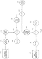
- Fig. 3 illustrates a flow diagram of a method for node de-duplication according to one embodiment.
- one or more nodes are discovered.
- the associated IP address of the node(s) is discovered.
- the supported technology used for obtaining device information such as SNMP, WMI, etc. is detected.
- information about the node(s) is obtained via the (detected) supported technology.
- de-duplication of the discovered node(s) is performed. It is determined whether the node(s) is a duplicate at 350. If it is, the duplicate node(s) is omitted from the discovered result set at 360. If the node(s) is not a duplicate, at 370, discovered node(s) are saved to the database.
- data associated with discovered node(s) are prepared for discovery import..
- Fig. 4 illustrates a flow diagram of a method for node de-duplication according to another embodiment.
- a result of a discovery job is saved.
- the discovery result is loaded and deserialized from the database.
- detection of duplicate is primarily done with primary IP address associated with the node.
- a duplicate check is performed against all monitored nodes at 440.
- result of discovery import is a list of nodes with associated IP addresses and MAC addresses.
- Fig. 5 illustrates a block diagram of an apparatus 10 that may implement one embodiment of the invention.
- Apparatus 10 may include a bus 12 or other communications mechanism for communicating information between components of apparatus 10.
- Apparatus 10 also includes a processor 22, coupled to bus 12, for processing information and executing instructions or operations.
- Processor 22 may be any type of general or specific purpose processor.
- Apparatus 10 further includes a memory 14 for storing information and instructions to be executed by processor 22.
- Memory 14 can be comprised of any combination of random access memory (“RAM”), read only memory (“ROM”), static storage such as a magnetic or optical disk, or any other type of machine or computer readable media.
- Apparatus 10 further includes a communication device 20, such as a network interface card or other communications interface, to provide access to a network. As a result, a user may interface with apparatus 10 directly or remotely through a network or any other method.
- Computer readable media may be any available media that can be accessed by processor 22 and includes both volatile and nonvolatile media, removable and non-removable media, and communication media.
- Communication media may include computer readable instructions, data structures, program modules or other data in a modulated data signal such as a carrier wave or other transport mechanism and includes any information delivery media.
- Processor 22 is further coupled via bus 12 to a presentation device 24, such as a display, monitor, screen, or web browser , for displaying information to a user, such as network traffic information.
- a user input component 26 such as a keyboard, computer mouse, or web browser, are further coupled to bus 12 to enable a user to interface with apparatus 10.
- Processor 22 and memory 14 may also be coupled via bus 12 to a database system 30 and, thus, may be able to access and retrieve information stored in database system 30.
- database system 30 is the network monitoring system storage 110 illustrated in Fig. 1 . Although only a single database is illustrated in Fig. 5 , any number of databases may be used in accordance with certain embodiments.
- memory 14 stores software modules that provide functionality when executed by processor 22.
- the modules may include an operating system 15 that provides operating system functionality for apparatus 10.
- the memory may also store one or more duplicate detector(s) 16, which supports a node deduplication functionality, as discussed above.
- the one or more duplicate detector(s) 16 may include, for example, IP address duplicate detector 201, DNS duplicate detector 203, MAC address duplicate detector 202, and Sysname duplicate detector 204, as depicted in Fig. 2 discussed above.
- Apparatus 10 may also include one or more other functional modules 18 to provide additional functionality.
- Database system 30 may include a database server and any type of database, such as a relational or flat file database.
- Database system 30 may store data related to network traffic flow of each of the entities in the network, and/or any data associated with apparatus 10 or its associated modules and components.
- processor 22, duplicate detector(s) 16, and other functional modules 18 may be implemented as separate physical and logical units or may be implemented in a single physical and logical unit. Furthermore, in some embodiments, processor 22, duplicate detector(s) 16, and other functional modules 18 may be implemented in hardware, or as any suitable combination of hardware and software.
- processor 22 is configured to control apparatus 10 to discover nodes in a network. According to an embodiment, information identifying the discovered nodes may be stored in database 110, for example. Processor 22 may be configured to control apparatus 10 to collect a list of IP addresses, MAC addresses, DNS names, and sysnames for each of the nodes discovered in the network.
- processor 22 may be configured to control apparatus 10 to execute an IP duplicate detector configured to compare the IP addresses of each of the discovered nodes with IP addresses of current nodes and other discovered nodes, a MAC duplicate detector configured to compare the MAC addresses of each of the discovered nodes with MAC addresses of the current nodes and the other discovered nodes, a DNS duplicate detector configured to compare the DNS names of each of the discovered nodes with DNS names of the current nodes and the other discovered nodes, and a name duplicate detector configured to compare the sysnames of each of the discovered nodes with sysnames of the current nodes and the other discovered nodes. Processor 22 may then be configured to control apparatus 10 to determine duplicate nodes that are duplicates of the other discovered nodes and/or the current nodes based on the result of comparison of the IP duplicate detector, the MAC duplicate detector, the DNS duplicate detector, and the name duplicate detector.
- processor 22 may be configured to control apparatus 10 to discard the duplicate nodes.
- processor 22 may be configured to control apparatus 10 to assign a priority to each of the IP duplicate detector, the MAC duplicate detector, the DNS duplicate detector, and the name duplicate detector that determines an order of execution.
- Apparatus 10 may be controlled to determine the duplicate nodes, for example, by executing the following formula: d 1 . IsDuplicate * d 1 . Priority + ... + d n . IsDuplicate * d n . Priority .
- each of the discovered nodes may be assigned a node ID.
- Processor 22 may be configured to control apparatus 10 to assign a Matchlndex to each node ID, where the Matchlndex indicates a likelihood of a match between the discovered node and any of the current nodes and the other discovered nodes.
- processor 22 may be configured to control apparatus 10 to group the duplicate nodes by node ID and to sum the Matchlndexes for the same node ID.
- a weight is assigned to each of the IP duplicate detector, the MAC duplicate detector, the DNS duplicate detector, and the name duplicate detector. The weight indicates the reliability of the result provided by the respective duplicate detectors.
- Fig. 6 illustrates an example flow chart of a method, according to one embodiment.
- the method includes, at 600, discovering, for example by a network monitoring apparatus, nodes in a network.
- the method may then include, at 610, collecting a list of internet protocol (IP) addresses, media access control (MAC) addresses, domain name system (DNS) names, and sysnames for each of the nodes discovered in the network.
- IP internet protocol
- MAC media access control
- DNS domain name system
- sysnames for each of the nodes discovered in the network.
- the method includes comparing the IP addresses of each of the discovered nodes with IP addresses of current nodes and other discovered nodes.
- the method includes comparing the MAC addresses of each of the discovered nodes with MAC addresses of the current nodes and the other discovered nodes.
- the method includes comparing the DNS names of each of the discovered nodes with DNS names of the current nodes and the other discovered nodes.
- the method includes comparing the sysnames of each of the discovered nodes with sysnames of the current nodes and the other discovered nodes.
- the method may further include, at 660, determining duplicate nodes that are duplicates of the other discovered nodes and/or the current nodes based on the comparison of the IP addresses, MAC addresses, DNS names, and sysnames.
- any of the methods described herein may be implemented by software and/or computer program code stored in memory or other computer readable or tangible media, and executed by a processor.
- the functionality may be performed by hardware, for example through the use of an application specific integrated circuit (ASIC), a programmable gate array (PGA), a field programmable gate array (FPGA), or any other combination of hardware and software.
- ASIC application specific integrated circuit
- PGA programmable gate array
- FPGA field programmable gate array
- One method includes discovering, by a network monitoring apparatus, nodes in a network, and collecting a list of internet protocol (IP) addresses, media access control (MAC) addresses, domain name system (DNS) names, and sysnames for each of the nodes discovered in the network.
- IP internet protocol
- MAC media access control
- DNS domain name system
- the method may also include comparing the collected list of information for each of the discovered nodes with corresponding information for current nodes and other discovered nodes.
- the method may then includes determining duplicate nodes that are duplicates of the other discovered nodes and/or the current nodes based on the comparison of the IP addresses, MAC addresses, DNS names, and sysnames.
Landscapes
- Engineering & Computer Science (AREA)
- Computer Networks & Wireless Communication (AREA)
- Signal Processing (AREA)
- Data Exchanges In Wide-Area Networks (AREA)
- Small-Scale Networks (AREA)
- Information Retrieval, Db Structures And Fs Structures Therefor (AREA)
Description
- Embodiments of the invention generally relate to network traffic monitoring, analysis, and/or reporting. More particularly, some embodiments are directed to methods, systems, and computer programs for node de-duplication of physical nodes monitored by a network monitoring system, for example.
- Network management includes activities, methods, procedures, and tools related to the operation, administration, maintenance, and/or provisioning of networked systems. Functions that can be performed as part of network management may include, for example, planning, controlling, deploying, allocating, coordinating, and monitoring the resources of a network. Further functions may be related to network planning, frequency allocation, load balancing, configuration management, fault management, security management, performance management, bandwidth management, route analytics, and accounting management.
- As mentioned above, a subset of network management includes network monitoring of network traffic. Network traffic data is of interest to network administrators for a number of reasons, including analyzing the impact of a new application on the network, troubleshooting network pain points, detecting slow or failing network devices, detecting heavy users of bandwidth, and securing networks. Various protocols for network traffic flow data have been developed. These protocols can contain numerous types of information, such as source internet protocol (IP) address, destination IP address, source port, destination port, IP protocol, ingress interface, IP Type of Service, start and finish times, number of bytes, and next hop.
- As networks become larger and more complex, systems that monitor, analyze, and report on traffic flow data must become more efficient at handling the increasing number of network devices and amount of information generated about
- The article entitled "Unique network node identification algorithm" by Hewlett-Packard Company et al., Research disclosure, vol. 582. no. 62, 1 October 2012, pages 838 to 840, ISSN 0374-4353, describes a unique network node identification algorithm, in which network devices are uniquely identified using a combination of MAC addresses on the device, IP addresses assigned to the device, the SNMP system object ID of the device, the DNS name of the device, and the tenant the device is assigned to.
- The article entitled "Mix-n-Match: Building Personal Libraries from Web Content" by Matthias Geel et al., Theory and Practice of Digital Libraries, 23 September 2012, pages 345 to 365, ISBN 978-3-642-33289-0, describes an approach to web content aggregation that allows information to be harvested from web pages, independent of specific markup languages. It is described that a content aggregation engine is realized as an extensive framework in a way that end users as well as developers can use the associated tools to crate personal libraries of content extracted from the web.
- According to the present invention, there are disclosed methods, apparatuses, and computer program products for node de-duplication, as defined in the appended claims.
- Certain embodiments are directed to methods, apparatuses, and computer program products for node de-duplication, which comprise, are configured to execute, and are configured to control a processor to execute a process comprising: discovering, by a network monitoring apparatus, nodes in a network, collecting a list of internet protocol (IP) addresses, media access control (MAC) addresses, domain name system (DNS) names, and sysnames for each of the nodes discovered in the network, comparing the IP addresses of each of the discovered nodes with IP addresses of current (monitored) nodes and other (previously) discovered nodes, comparing the MAC addresses of each of the discovered nodes with MAC addresses of the current (monitored) nodes and the other (previously) discovered nodes, comparing the DNS names of each of the discovered nodes with DNS names of the current (monitored) nodes and the other (previously) discovered nodes, comparing the sysnames of each of the discovered nodes with sysnames of the current (monitored) nodes and the other (previously) discovered nodes, and determining duplicate nodes that are duplicates of the other (previously) discovered nodes and/or the current (monitored) nodes based on the comparison of the IP addresses, MAC addresses, DNS names, and sysnames, wherein, for the determining, each of the discovered nodes is assigned a node ID, and a MatchIndex is assigned to each node ID, the MatchIndex indicating a likelihood of a match between the discovered node and any of the current (monitored) nodes and the other (previously) discovered nodes.
- For proper understanding of the invention, reference should be made to the accompanying drawings, wherein:
-
Fig. 1 illustrates a block diagram of a system according to an embodiment; -
Fig. 2 illustrates a block diagram of a system according to one embodiment; -
Fig. 3 illustrates a flow diagram of a method according to one embodiment; -
Fig. 4 illustrates a flow diagram of a method according to another embodiment; -
Fig. 5 illustrates a block diagram of an apparatus according to an embodiment; and -
Fig. 6 illustrates a flow diagram of a method according to another embodiment. - It will be readily understood that the components of the invention, as generally described and illustrated in the figures herein, may be arranged and designed in a wide variety of different configurations. Thus, the following detailed description of the embodiments of systems, methods, apparatuses, and computer program products for node de-duplication, as represented in the attached figures, is not intended to limit the scope of the invention, but is merely representative of selected embodiments of the invention.
- The features, structures, or characteristics of the invention described throughout this specification may be combined in any suitable manner in one or more embodiments. For example, the usage of the phrases "certain embodiments," "some embodiments," or other similar language, throughout this specification refers to the fact that a particular feature, structure, or characteristic described in connection with the embodiment may be included in at least one embodiment of the present invention. Thus, appearances of the phrases "in certain embodiments," "in some embodiments," "in other embodiments," or other similar language, throughout this specification do not necessarily all refer to the same group of embodiments, and the described features, structures, or characteristics may be combined in any suitable manner in one or more embodiments. Additionally, if desired, the different functions discussed below may be performed in a different order and/or concurrently with each other. Furthermore, if desired, one or more of the described functions may be optional or may be combined. As such, the following description should be considered as merely illustrative of the principles, teachings and embodiments of this invention, and not in limitation thereof.
- It should be noted that throughout this specification the terms network devices and network nodes, or simply devices or nodes, may be used interchangeably to refer to any physical device that is capable of connecting to and/or communicating on a network. Examples of such devices or nodes may include, but is not limited to, routers, switches, servers, computers, laptops, tablets, telephones, printers, mobile devices, and any other current or future component capable of sending, receiving, or forwarding information over a communications channel.
-
Fig. 1 illustrates an example of a system according to one embodiment. The system includesnetwork monitoring system 100, networkmonitoring system storage 110,switch device 130, and one ormore network devices 120. Networkmonitoring system storage 110 can store network monitoring data. Networkmonitoring system storage 110 can be a database or any other appropriate storage device.Network devices 120 may be nodes in the network that are monitored bynetwork traffic monitor 100. It should be noted that any number and type ofnetwork devices 120 can be supported in the system. Accordingly, embodiments are not limited to the number and type of network devices illustrated inFig. 1 . In an embodiment, networkmonitoring system storage 110 may store discovery result database tables that store and organize information about discovered network devices in the network. - In some cases, network devices can be accessible on multiple internet protocol (IP) addresses. For example, some devices can simultaneously have more than one IP address. Also, some nodes are dynamic in that they have IP addresses that vary in time. Such dynamic IP addresses cause problems for de-duplication logic because it might be matching an outdated primary IP address from discovery result with the current IP address of a dynamic node.
- Currently, systems generally apply logic where one IP address equals one network node. As a result, nodes with multiple IP address bindings may not be recognized as a single node. This behavior can result in a state where one physical device is being monitored more than once, which can obviously cause additional overhead and inefficiencies in the network monitoring system.
- Therefore, users usually want to have devices which respond on multiple IP addresses monitored as a single node in the network. Embodiments of the invention implement an automatic network discovery that is able to detect such situation and avoid processing the same physical node multiple times (e.g., each time using a different IP address). One embodiment includes a de-duplication logic configured to automatically identify duplicate nodes such that a single node is not monitored multiple times.
- Certain embodiments identify one or more pieces of information that function as a node identifier needed to uniquely identify the network node. Having this unique node identifier, certain embodiments can proceed with defining logic, which detects duplicates within nodes found during the discovery process (e.g., same physical network node under different IP addresses) and/or within nodes already being monitored under a different IP address.
- According to certain embodiments, the information used to uniquely identify nodes includes information which can be polled easily, is available for a majority of devices (i.e., vendor independent), is available for Internet Control Message Protocol (ICMP) nodes as well as other types of nodes (e.g., ICMP nodes can be considered to be nodes not reachable over SNMP or WMI), and is a minimal set of information that can still provide accurate results while being efficient.
- Certain embodiments can handle at least two typical uses cases. For example, one use case may include running an automated network discovery over a subnetwork, which contains devices accessible on multiple IP addresses. As is known, devices that belong to a subnet are addressed with a common, identical, most-significant bit-group in their IP address. Another use case may include running an automated network discovery over a subnetwork, which is already being monitored.
- Certain embodiments are able to identify network nodes as network duplicates, even if one set of information was collected in a different time frame than the other. For instance, this may occur when a user decides to import discovery results for a scheduled discovery profile. In such a case, some embodiments may need to work with possibly outdated information collected during discovery and compare it to new information, which is being continuously collected for all monitored nodes. Accordingly, de-duplication according to certain embodiments can take place during a discovery job where discovered nodes are compared to each other such that duplicates are removed, and/or can take place during a discovery result importing where discovered nodes are imported and compared against existing nodes (e.g., nodes stored in network monitoring system storage or database) such that duplicate nodes are identified and removed.
- According to an embodiment, a data collection set made up of DNS name, Sysname, IP address, and MAC address for each network node is used to help identify duplicate nodes. One embodiment includes logic which compares pieces of information from the data collection set against each other, for example DNS to DNS, MACs to MACs, etc. The logic may be implemented in a Duplicate Detector component. A result from the detection is the match index, which indicates whether there is a match, no match, or unkown.. Certain embodiments also provide logic for aggregating partial results from detectors and calculating a final verdict as to whether a node is a duplicate or not. For example, in an embodiment, the node de-duplication may include several sub-iterations that are each responsible for discovering selected IP-range. At the end of every iteration, de-duplication is performed to omit nodes (e.g., endpoints) as soon as they are thought to be duplicates. In case of an unknown or non-duplicate result for one iteration, the node is passed to the next step or iteration for processing.
- In an embodiment, two sets of duplicate detectors may be provided. One set of detectors can be used during the automated discovery process to filter out newly found devices and remove duplicates. Another set of detectors can be used during discovery result import to avoid adding duplicate nodes into set of monitored nodes.
- In one embodiment, the system is configured to collect list of all DNS names, Sysnames, IP addresses, and MAC addresses for all discovered nodes, and to store them, for example, as part of a discovery job result. This information may be stored in the network system monitoring storage or
database 110. As mentioned above, this information can be used during at least two phases of discovery. For instance, the DNS names, Sysnames, IP addresses, and MAC addresses can be used when running discovery to check whether currently discovered node(s) are a duplicate of any other already found, and/or can be used during discovery result importing to compare discovery result(s) with existing nodes monitored by the system. In one embodiment, the MAC information is stored to a persistent storage, for example, as part of discovery result. -
Fig. 2 illustrates asystem 200, according to one embodiment, which may include an IPaddress duplicate detector 201, aDNS duplicate detector 203, a MACaddress duplicate detector 202, and aSysname duplicate detector 204. In an embodiment, adatabase 210 may be in communication with the IPaddress duplicate detector 201,DNS duplicate detector 203, MACaddress duplicate detector 202, andSysname duplicate detector 204 such that each of the detectors can collect the relevant addresses stored in thedatabase 210. In an embodiment, thedatabase 210 may be stored in the networktraffic data storage 110 illustrated inFig. 1 . It should be noted thatsystem 200 can be implemented completely in hardware, or in a combination of hardware and software. - Each of the
duplicate detectors -
DNS duplicate detector 203 may be configured to compare a DNS of a discovered node with all other discovered nodes and current nodes being monitored. In an embodiment,DNS duplicate detector 203 may conclude that a node is a duplicate if the DNS of a discovered node is the same as a DNS used by any of the monitored nodes or any of the other discovered nodes. - MAC addresses are generally unique by design (although there are situations where the same MAC address is used on two different devices, for example cloned virtual machines hosted in two separated virtual hosts). MAC
address duplicate detector 202 may be configured to compare a MAC address of a discovered node against all previously collected MAC addresses of nodes, which may be stored in a NodeMACAddresses database table indatabase 210. MACaddress duplicate detector 202 may be configured to conclude that a node is a duplicate if a set of discovered MAC addresses is a sub-set of currently monitored MAC addresses for a node or if a set of monitored MAC addresses is sub-set of discovered MAC addresses. - Table 1 below illustrates an example where the nodes are considered equal according to the MAC
address duplicate detector 202, where A,B,C,... represent MAC addresses. Meanwhile, Table 2 below illustrates an example where the nodes are not considered equal (e.g., based on MAC addresses).TABLE 1 Node A Node B Node C Node D A A A A B B B B C C C D TABLE 2 Node A Node B Node C Node D A A D A B B E D C D F - Two nodes, which both have just two MAC addresses, for instance 0000000000000000 and 00000000000000E0 should be considered as equal. For instance, Node A and Node B are equal when and only when Node A 's list of MAC addresses is subset of Node B' s list of MAC addresses or Node B 's list of MACs is subset of Node A 's list of MAC.In that case, the system may look to a different duplicate detector or different de-duplication method (e.g., sysname matching) since, according to MAC addresses, the two nodes are equal.
-
Sysname duplicate detector 204 may be configured to compare a sysname of a discovered node with all other discovered nodes and current nodes being monitored. In an embodiment,Sysname duplicate detector 204 may conclude that a node is a duplicate if the Sysname of a discovered node is the same as a Sysname used by any of the monitored nodes or any of the other discovered nodes. In an embodiment, the Sysname may be the Sysname for Simple Network Management Protocol (SNMP) nodes or may be the full computer name for window management instrumentation (WMI) nodes, for example. It should be noted that embodiments do not limit data sources to SNMP and/or WMI, and other types of data sources are equally applicable according to certain embodiments (e.g., CLI over SSH on routers/switches or telnet, etc.). - As mentioned above, each duplicate detector may load an associated weight from a settings database table. The weight represents the reliability of the result provided by the associated duplicate detector. It is possible to set the weight to -1 to disable the associated duplicate detector. According to an embodiment, weight values may range from 0 to 100 where 0 represents the least reliable and 100 represents the most reliable.
- All of the duplicate detectors (d1, ..., dn) may be executed sequentially with order defined by priority, as discussed above. Each of the duplicate detectors may set an 'IsAuthoritative' flag to be true, which may then terminate execution of following duplicate detectors. In such a case, the vote of the duplicate detector with the 'IsAuthoritative' flag set to true is considered as final, ignoring all other votes. According to one embodiment, if there is no 'IsAuthoritative' flag set to true, a final result as to whether a node is a duplicate is computed as a sum of all duplicate detector vote result values as follows:

- As illustrated in Table 3 below, Each duplicate detector may return a list of node IDs for all duplicate nodes it finds. Each node ID may have an associated Matchlndex assigned, which indicates the likelihood of the match. In an embodiment, the range of Matchlndex values is 0 to 100, where 0 indicates the least likelihood of a match and 100 indicates the greatest likelihood of a match. According to an embodiment,
system 200 may be configured to group the duplicate node information depicted in Table 3 by node ID, and to sum the Matchlndexes for the same node ID. Then,system 200 may be configured to select the node ID with the highest summed total Matchlndex for discarding.TABLE 3 Duplicate Detector DuplicateNodeID MatchIndex Dns 5 90 Mac 1 60 Mac 5 80 Sysname 5 85 Final Decision: 5 90 - Table 4 below illustrates an example results table, according to an embodiment. In this example, each row of the table may represent a node. The 'DnsDuplicateDetector' column shows the conclusion of the DNS duplicate detector as to whether the node is a duplicate or not. Similarly, the 'MacAddressDuplicateDetector' column shows the conclusion of the MAC address duplicate detector as to whether the node is a duplicate or not, and the 'NameDuplicateDetector' column shows the conclusion of the Sysname duplicate detector as to whether the node is a duplicate or not. Then, the final 'Expected Result' column shows the expected result for the node.


-
Fig. 3 illustrates a flow diagram of a method for node de-duplication according to one embodiment. In the example ofFig. 3 , at 300, one or more nodes are discovered. At 310, the associated IP address of the node(s) is discovered. At 320, the supported technology used for obtaining device information, such as SNMP, WMI, etc. is detected. At 330, information about the node(s) is obtained via the (detected) supported technology. At 340, de-duplication of the discovered node(s) is performed. It is determined whether the node(s) is a duplicate at 350. If it is, the duplicate node(s) is omitted from the discovered result set at 360. If the node(s) is not a duplicate, at 370, discovered node(s) are saved to the database. At 380, data associated with discovered node(s) are prepared for discovery import.. -
Fig. 4 illustrates a flow diagram of a method for node de-duplication according to another embodiment. In the example ofFig. 4 , at 400, a result of a discovery job is saved. At 405, the discovery result is loaded and deserialized from the database. At 410, detection of duplicate is primarily done with primary IP address associated with the node. At 415, it is detected whether node with same IP is already monitored by any engine. If node with same IP is already monitored, the existing node information is updated at 420. If node with same IP is not already monitored, duplicate detection against ignored nodes is performed at 425. At 430, it is determined whether node is a duplicate. If so, the conditions are logged and the duplicate node is discarded at 435. If it is not determined as a duplicate, a duplicate check is performed against all monitored nodes at 440. At 445, it is determined whether node is a duplicate. If it is determined as duplicate, the conditions are logged and the duplicate node is discarded at 450. If it is not determined as a duplicate, node(s) information is saved to persistent storage at 455. At 460, result of discovery import is a list of nodes with associated IP addresses and MAC addresses. -
Fig. 5 illustrates a block diagram of anapparatus 10 that may implement one embodiment of the invention.Apparatus 10 may include a bus 12 or other communications mechanism for communicating information between components ofapparatus 10.Apparatus 10 also includes aprocessor 22, coupled to bus 12, for processing information and executing instructions or operations.Processor 22 may be any type of general or specific purpose processor.Apparatus 10 further includes amemory 14 for storing information and instructions to be executed byprocessor 22.Memory 14 can be comprised of any combination of random access memory ("RAM"), read only memory ("ROM"), static storage such as a magnetic or optical disk, or any other type of machine or computer readable media.Apparatus 10 further includes acommunication device 20, such as a network interface card or other communications interface, to provide access to a network. As a result, a user may interface withapparatus 10 directly or remotely through a network or any other method. - Computer readable media may be any available media that can be accessed by
processor 22 and includes both volatile and nonvolatile media, removable and non-removable media, and communication media. Communication media may include computer readable instructions, data structures, program modules or other data in a modulated data signal such as a carrier wave or other transport mechanism and includes any information delivery media. -
Processor 22 is further coupled via bus 12 to apresentation device 24, such as a display, monitor, screen, or web browser , for displaying information to a user, such as network traffic information. A user input component 26 , such as a keyboard, computer mouse, or web browser, are further coupled to bus 12 to enable a user to interface withapparatus 10.Processor 22 andmemory 14 may also be coupled via bus 12 to adatabase system 30 and, thus, may be able to access and retrieve information stored indatabase system 30. In one embodiment,database system 30 is the networkmonitoring system storage 110 illustrated inFig. 1 . Although only a single database is illustrated inFig. 5 , any number of databases may be used in accordance with certain embodiments. - In one embodiment,
memory 14 stores software modules that provide functionality when executed byprocessor 22. The modules may include anoperating system 15 that provides operating system functionality forapparatus 10. The memory may also store one or more duplicate detector(s) 16, which supports a node deduplication functionality, as discussed above. The one or more duplicate detector(s) 16 may include, for example, IPaddress duplicate detector 201,DNS duplicate detector 203, MACaddress duplicate detector 202, andSysname duplicate detector 204, as depicted inFig. 2 discussed above.Apparatus 10 may also include one or more otherfunctional modules 18 to provide additional functionality. -
Database system 30 may include a database server and any type of database, such as a relational or flat file database.Database system 30 may store data related to network traffic flow of each of the entities in the network, and/or any data associated withapparatus 10 or its associated modules and components. - In certain embodiments,
processor 22, duplicate detector(s) 16, and otherfunctional modules 18 may be implemented as separate physical and logical units or may be implemented in a single physical and logical unit. Furthermore, in some embodiments,processor 22, duplicate detector(s) 16, and otherfunctional modules 18 may be implemented in hardware, or as any suitable combination of hardware and software. - In some embodiments,
processor 22 is configured to controlapparatus 10 to discover nodes in a network. According to an embodiment, information identifying the discovered nodes may be stored indatabase 110, for example.Processor 22 may be configured to controlapparatus 10 to collect a list of IP addresses, MAC addresses, DNS names, and sysnames for each of the nodes discovered in the network. - According to one embodiment,
processor 22 may be configured to controlapparatus 10 to execute an IP duplicate detector configured to compare the IP addresses of each of the discovered nodes with IP addresses of current nodes and other discovered nodes, a MAC duplicate detector configured to compare the MAC addresses of each of the discovered nodes with MAC addresses of the current nodes and the other discovered nodes, a DNS duplicate detector configured to compare the DNS names of each of the discovered nodes with DNS names of the current nodes and the other discovered nodes, and a name duplicate detector configured to compare the sysnames of each of the discovered nodes with sysnames of the current nodes and the other discovered nodes.Processor 22 may then be configured to controlapparatus 10 to determine duplicate nodes that are duplicates of the other discovered nodes and/or the current nodes based on the result of comparison of the IP duplicate detector, the MAC duplicate detector, the DNS duplicate detector, and the name duplicate detector. - In an embodiment,
processor 22 may be configured to controlapparatus 10 to discard the duplicate nodes. According to one embodiment,processor 22 may be configured to controlapparatus 10 to assign a priority to each of the IP duplicate detector, the MAC duplicate detector, the DNS duplicate detector, and the name duplicate detector that determines an order of execution.Apparatus 10 may be controlled to determine the duplicate nodes, for example, by executing the following formula:
- In an embodiment, each of the discovered nodes may be assigned a node ID.
Processor 22 may be configured to controlapparatus 10 to assign a Matchlndex to each node ID, where the Matchlndex indicates a likelihood of a match between the discovered node and any of the current nodes and the other discovered nodes. According to one embodiment,processor 22 may be configured to controlapparatus 10 to group the duplicate nodes by node ID and to sum the Matchlndexes for the same node ID. Additionally, a weight is assigned to each of the IP duplicate detector, the MAC duplicate detector, the DNS duplicate detector, and the name duplicate detector. The weight indicates the reliability of the result provided by the respective duplicate detectors. -
Fig. 6 illustrates an example flow chart of a method, according to one embodiment. The method includes, at 600, discovering, for example by a network monitoring apparatus, nodes in a network. The method may then include, at 610, collecting a list of internet protocol (IP) addresses, media access control (MAC) addresses, domain name system (DNS) names, and sysnames for each of the nodes discovered in the network. At 620, the method includes comparing the IP addresses of each of the discovered nodes with IP addresses of current nodes and other discovered nodes, At 630, the method includes comparing the MAC addresses of each of the discovered nodes with MAC addresses of the current nodes and the other discovered nodes. At 640, the method includes comparing the DNS names of each of the discovered nodes with DNS names of the current nodes and the other discovered nodes. At 650, the method includes comparing the sysnames of each of the discovered nodes with sysnames of the current nodes and the other discovered nodes. The method may further include, at 660, determining duplicate nodes that are duplicates of the other discovered nodes and/or the current nodes based on the comparison of the IP addresses, MAC addresses, DNS names, and sysnames. - In some embodiments, the functionality of any of the methods described herein, such as those of
Figs. 3 ,4 , and6 , may be implemented by software and/or computer program code stored in memory or other computer readable or tangible media, and executed by a processor. In other embodiments, the functionality may be performed by hardware, for example through the use of an application specific integrated circuit (ASIC), a programmable gate array (PGA), a field programmable gate array (FPGA), or any other combination of hardware and software. - One having ordinary skill in the art will readily understand that the invention as discussed above may be practiced with steps in a different order, and/or with hardware elements in configurations which are different than those which are disclosed. Therefore, although the invention has been described based upon these preferred embodiments, it would be apparent to those of skill in the art that certain modifications, variations, and alternative constructions would be apparent, without departing from the present invention as defined in the appended claims.
- As evident from the above, there are disclosed systems, methods, apparatuses, and computer program products for node de-duplication. One method includes discovering, by a network monitoring apparatus, nodes in a network, and collecting a list of internet protocol (IP) addresses, media access control (MAC) addresses, domain name system (DNS) names, and sysnames for each of the nodes discovered in the network. The method may also include comparing the collected list of information for each of the discovered nodes with corresponding information for current nodes and other discovered nodes. The method may then includes determining duplicate nodes that are duplicates of the other discovered nodes and/or the current nodes based on the comparison of the IP addresses, MAC addresses, DNS names, and sysnames.
Claims (12)
- A method, comprising:discovering (600), by a network monitoring apparatus, nodes in a network;collecting (610) a list of internet protocol, IP, addresses, media access control, MAC, addresses, domain name system, DNS, names, and sysnames for each of the nodes discovered in the network;comparing (620) the IP addresses of each of the discovered nodes with IP addresses of monitored nodes and previously discovered nodes;comparing (630) the MAC addresses of each of the discovered nodes with MAC addresses of the monitored nodes and the previously discovered nodes;comparing (640) the DNS names of each of the discovered nodes with DNS names of the monitored nodes and the previously discovered nodes;comparing (650) the sysnames of each of the discovered nodes with sysnames of the monitored nodes and the previously discovered nodes;determining (660) duplicate nodes that are duplicates of the previously discovered nodes and/or the monitored nodes based on the comparison of the IP addresses, MAC addresses, DNS names, and sysnames,wherein, for the determining, each of the discovered nodes is assigned a node ID, and the method further comprises assigning a MatchIndex to each node ID, the MatchIndex indicating a likelihood of a match between the discovered node and any of the monitored nodes and the previously discovered nodes.
- The method according to claim 1, further comprising discarding (435) the duplicate nodes.
- The method according to claim 1, further comprising assigning a priority to each of the comparing steps that determines an order of execution.
- The method according to claim 1, wherein the determining is performed using a plurality of duplicate detectors, each duplicate detector being configured to perform one of the comparisons, and comprises executing the following formula to compute a final result as to whether a discovered node is a duplicate:

- The method according to any one of claims 1 to 4, further comprising grouping the duplicate nodes by node ID and summing the MatchIndexes for the same node ID.
- An apparatus, comprising:at least one processor (22) and at least one memory (14) including computer program code,the at least one memory and the computer program code are configured, with the at least one processor, to cause the apparatus at least todiscover (600) nodes in a network;collect (610) a list of internet protocol, IP, addresses, media access control, MAC, addresses, domain name system, DNS, names, and sysnames for each of the nodes discovered in the network;wherein the at least one processor is further configured to execute:an IP duplicate detector (16, 201) configured to compare (620) the IP addresses of each of the discovered nodes with IP addresses of monitored nodes and previously discovered nodes;a MAC duplicate detector (16, 202) configured to compare (630) the MAC addresses of each of the discovered nodes with MAC addresses of the monitored nodes and the previously discovered nodes;a DNS duplicate detector (16, 203) configured to compare (640) the DNS names of each of the discovered nodes with DNS names of the monitored nodes and the previously discovered nodes;a name duplicate detector (16, 204) configured to compare (650) the sysnames of each of the discovered nodes with sysnames of the monitored nodes and the previously discovered nodes;wherein the at least one memory and the computer program code are further configured, with the at least one processor, to cause the apparatus at least todetermine (660) duplicate nodes that are duplicates of the previously discovered nodes and/or the monitored nodes based on the result of comparison of the IP duplicate detector, the MAC duplicate detector, the DNS duplicate detector, and the name duplicate detector,wherein, for the determining, each of the discovered nodes is assigned a node ID, and the at least one memory and the computer program code are further configured, with the at least one processor, to cause the apparatus at least to assign a MatchIndex to each node ID, the MatchIndex indicating a likelihood of a match between the discovered node and any of the monitored nodes and the previously discovered nodes.
- The apparatus according to claim 6, wherein the at least one memory and the computer program code are further configured, with the at least one processor, to cause the apparatus at least to discard (435) the duplicate nodes.
- The apparatus according to claim 6, wherein the at least one memory and the computer program code are further configured, with the at least one processor, to cause the apparatus at least to assign a priority to each of the IP duplicate detector, the MAC duplicate detector, the DNS duplicate detector, and the name duplicate detector that determines an order of execution.
- The apparatus according to claim 6, wherein the at least one memory and the computer program code are further configured, with the at least one processor, to cause the apparatus at least to determine the duplicate nodes by executing the following formula to compute a final result as to whether a discovered node is a duplicate:

- The apparatus according to any one of claims 6 to 9, wherein the at least one memory and the computer program code are further configured, with the at least one processor, to cause the apparatus at least to group the duplicate nodes by node ID and to sum the MatchIndexes for the same node ID.
- The apparatus according to claim 6, wherein a weight is assigned to each of the IP duplicate detector, the MAC duplicate detector, the DNS duplicate detector, and the name duplicate detector, wherein the weight indicates the reliability of the result provided by the respective duplicate detectors.
- A computer program, embodied on a computer readable medium, comprising instructions which, when the computer program is executed by a processor, cause the processor to carry out the steps of:discovering (600), by a network monitoring apparatus, nodes in a network;collecting (610) a list of internet protocol, IP, addresses, media access control, MAC, addresses, domain name system, DNS, names, and sysnames for each of the nodes discovered in the network;comparing (620) the IP addresses of each of the discovered nodes with IP addresses of monitored nodes and previously discovered nodes;comparing (630) the MAC addresses of each of the discovered nodes with MAC addresses of the monitored nodes and the previously discovered nodes;comparing (640) the DNS names of each of the discovered nodes with DNS names of the monitored nodes and the previously discovered nodes;comparing (650) the sysnames of each of the discovered nodes with sysnames of the monitored nodes and the previously discovered nodes; anddetermining (660) duplicate nodes that are duplicates of the previously discovered nodes and/or the monitored nodes based on the comparison of the IP addresses, MAC addresses, DNS names, and sysnames,wherein, for the determining, each of the discovered nodes is assigned a node ID, and the process further comprises assigning a MatchIndex to each node ID, the MatchIndex indicating a likelihood of a match between the discovered node and any of the monitored nodes and the previously discovered nodes.
Priority Applications (1)
| Application Number | Priority Date | Filing Date | Title |
|---|---|---|---|
| PL14191409T PL2869495T3 (en) | 2013-11-05 | 2014-11-03 | Node de-duplication in a network monitoring system |
Applications Claiming Priority (1)
| Application Number | Priority Date | Filing Date | Title |
|---|---|---|---|
| US14/072,150 US9584367B2 (en) | 2013-11-05 | 2013-11-05 | Node de-duplication in a network monitoring system |
Publications (2)
| Publication Number | Publication Date |
|---|---|
| EP2869495A1 EP2869495A1 (en) | 2015-05-06 |
| EP2869495B1 true EP2869495B1 (en) | 2018-01-10 |
Family
ID=51900121
Family Applications (1)
| Application Number | Title | Priority Date | Filing Date |
|---|---|---|---|
| EP14191409.3A Active EP2869495B1 (en) | 2013-11-05 | 2014-11-03 | Node de-duplication in a network monitoring system |
Country Status (13)
| Country | Link |
|---|---|
| US (1) | US9584367B2 (en) |
| EP (1) | EP2869495B1 (en) |
| JP (1) | JP5950979B2 (en) |
| CN (1) | CN104618521B (en) |
| AU (2) | AU2014259482A1 (en) |
| CA (1) | CA2869071A1 (en) |
| DK (1) | DK2869495T3 (en) |
| ES (1) | ES2658980T3 (en) |
| IN (1) | IN2014DE03112A (en) |
| NO (1) | NO2969751T3 (en) |
| PL (1) | PL2869495T3 (en) |
| PT (1) | PT2869495T (en) |
| SG (1) | SG10201407116SA (en) |
Families Citing this family (13)
| Publication number | Priority date | Publication date | Assignee | Title |
|---|---|---|---|---|
| US20170061339A1 (en) | 2014-01-02 | 2017-03-02 | Jeremy Lynn Littlejohn | Method for facilitating network external computing assistance |
| US20160373319A1 (en) * | 2014-09-24 | 2016-12-22 | Jeremy Lynn Littlejohn | Method and device for evaluating the system assets of a communication network |
| US9977817B2 (en) * | 2014-10-20 | 2018-05-22 | Conduent Business Services, Llc | Matching co-referring entities from serialized data for schema inference |
| US9992082B2 (en) * | 2015-12-04 | 2018-06-05 | CENX, Inc. | Classifier based graph rendering for visualization of a telecommunications network topology |
| EP3352416B1 (en) * | 2017-01-19 | 2019-05-15 | Deutsche Telekom AG | Network inventory control system |
| WO2018186511A1 (en) * | 2017-04-06 | 2018-10-11 | (주)노르마 | System for preventing arp spoofing in internet of things network |
| KR102156331B1 (en) * | 2018-07-13 | 2020-09-15 | 중앙대학교 산학협력단 | Bitcoin network scanning system and method |
| CN109462668B (en) * | 2018-10-25 | 2020-11-10 | 维沃移动通信有限公司 | Method and device for processing domain name resolution request |
| CN111511016B (en) * | 2020-04-09 | 2021-10-08 | 腾讯科技(深圳)有限公司 | Method, device, server and storage medium for determining homologous wireless network |
| JP7585005B2 (en) * | 2020-11-19 | 2024-11-18 | キヤノン株式会社 | Information processing device, image processing device, and method and program for controlling the information processing device |
| CN113938434A (en) * | 2021-10-12 | 2022-01-14 | 上海交通大学 | Large-scale high-performance RoCEv2 network construction method and system |
| US12386956B1 (en) | 2021-10-26 | 2025-08-12 | NTT DATA Services, LLC | Automatic discovery and enterprise control of a robotic workforce |
| US12591704B2 (en) * | 2023-11-28 | 2026-03-31 | International Business Machines Corporation | Entity-wide database asset index generation |
Family Cites Families (64)
| Publication number | Priority date | Publication date | Assignee | Title |
|---|---|---|---|---|
| US3653729A (en) * | 1969-12-19 | 1972-04-04 | Westinghouse Air Brake Co | Electrically controlled hydraulic valve of self-lapping type |
| US4170147A (en) * | 1977-10-27 | 1979-10-09 | United Technologies Corporation | Redundant flight control system |
| FR2513468B1 (en) * | 1981-09-18 | 1986-02-14 | Cit Alcatel | DEFENSE DEVICE OF A SELF-SWITCHING APPARATUS WITH DISTRIBUTED CONTROL |
| US5572421A (en) * | 1987-12-09 | 1996-11-05 | Altman; Louis | Portable medical questionnaire presentation device |
| US5129076A (en) * | 1989-03-20 | 1992-07-07 | International Business Machines Corporation | Optical disk library control system providing an enhanced initialization technique |
| JPH0370048A (en) * | 1989-08-09 | 1991-03-26 | Hitachi Ltd | How to create a dictionary |
| US5111395A (en) * | 1989-11-03 | 1992-05-05 | Smith Rodney A | Automated fund collection system including means to eliminate duplicate entries from a mailing list |
| CA2075048C (en) * | 1990-01-30 | 1999-08-17 | Gregory A. Pascucci | Networked facilities management system |
| EP0472829A3 (en) * | 1990-08-31 | 1993-01-07 | International Business Machines Corporation | Multicomputer complex and distributed shared data memory |
| US5249188A (en) * | 1991-08-26 | 1993-09-28 | Ag Communication Systems Corporation | Synchronizing two processors as an integral part of fault detection |
| JP3175399B2 (en) * | 1993-05-18 | 2001-06-11 | セイコーエプソン株式会社 | Card data management device |
| US5577252A (en) * | 1993-07-28 | 1996-11-19 | Sun Microsystems, Inc. | Methods and apparatus for implementing secure name servers in an object-oriented system |
| US5530849A (en) * | 1993-08-16 | 1996-06-25 | Cornell Research Foundation, Inc. | Method of reading dynamic, hierarchical file system directories |
| US5619656A (en) * | 1994-05-05 | 1997-04-08 | Openservice, Inc. | System for uninterruptively displaying only relevant and non-redundant alert message of the highest severity for specific condition associated with group of computers being managed |
| WO1996032685A1 (en) * | 1995-04-11 | 1996-10-17 | Kinetech, Inc. | Identifying data in a data processing system |
| US5995999A (en) * | 1997-03-12 | 1999-11-30 | Fujitsu Limited | Naming system for hierarchically named computer accessible objects |
| JP3782867B2 (en) * | 1997-06-25 | 2006-06-07 | 株式会社日立製作所 | Information reception processing method and computer / telephony integration system |
| US6108649A (en) * | 1998-03-03 | 2000-08-22 | Novell, Inc. | Method and system for supplanting a first name base with a second name base |
| DE60041732D1 (en) * | 1999-01-27 | 2009-04-23 | Hitachi Ltd | Method, device and storage medium for use in a hierarchical system |
| US6332142B1 (en) * | 1999-04-26 | 2001-12-18 | 3Com Corporation | Management information base attribute discriminator |
| US6513710B1 (en) * | 1999-05-20 | 2003-02-04 | Temtec, Inc. | Trade show attendee control, lead collection and event control system |
| US6744436B1 (en) * | 1999-05-25 | 2004-06-01 | Anthony Chirieleison, Jr. | Virtual reality warehouse management system complement |
| US6449657B2 (en) * | 1999-08-06 | 2002-09-10 | Namezero.Com, Inc. | Internet hosting system |
| US20010049747A1 (en) * | 1999-08-06 | 2001-12-06 | Namezero.Com, Inc. | Multi-threaded name server |
| JP3874593B2 (en) | 2000-06-12 | 2007-01-31 | 株式会社日立製作所 | Computer identification device |
| US7844823B2 (en) * | 2000-08-10 | 2010-11-30 | Shield Security Systems, Llc | Interactive security control system with conflict checking |
| US7702913B2 (en) * | 2000-08-10 | 2010-04-20 | Shield Security Systems, Llc | Interactive security control system with real time activity reports |
| US7120935B2 (en) * | 2000-08-10 | 2006-10-10 | Shield Security Systems, Llc | Interactive key control system and method of managing access to secured locations |
| GB0022485D0 (en) * | 2000-09-13 | 2000-11-01 | Apl Financial Services Oversea | Monitoring network activity |
| US6636875B1 (en) * | 2000-10-25 | 2003-10-21 | International Business Machines Corporation | System and method for synchronizing related data elements in disparate storage systems |
| US20020124066A1 (en) * | 2000-12-15 | 2002-09-05 | International Business Machines Corporation | Method and system for unambiguous addressability in a distributed application framework in which duplicate network addresses exist across multiple customer networks |
| US6917970B2 (en) * | 2001-03-09 | 2005-07-12 | Sun Microsystems, Inc. | Method and program code for identifying new nodes on a bus following a reset |
| US7734739B2 (en) * | 2001-04-20 | 2010-06-08 | Hewlett-Packard Development Company, L.P. | Method and system for consolidating network topology in duplicate IP networks |
| US20020169738A1 (en) * | 2001-05-10 | 2002-11-14 | Giel Peter Van | Method and system for auditing an enterprise configuration |
| EP1271843B1 (en) | 2001-06-18 | 2007-08-15 | Hewlett-Packard Company | A method and system for identifying network connected devices such as personal computers |
| US20030020749A1 (en) * | 2001-07-10 | 2003-01-30 | Suhayya Abu-Hakima | Concept-based message/document viewer for electronic communications and internet searching |
| JP2003030016A (en) * | 2001-07-11 | 2003-01-31 | Hitachi Ltd | Data conversion method and system, and processing program therefor |
| US6985926B1 (en) * | 2001-08-29 | 2006-01-10 | I-Behavior, Inc. | Method and system for matching and consolidating addresses in a database |
| US7266678B2 (en) * | 2001-11-06 | 2007-09-04 | Dell Products L.P. | Dynamic configuration of computer when booting |
| US20040059706A1 (en) * | 2002-09-25 | 2004-03-25 | International Business Machines Corporation | System and method for providing concurrent usage and replacement of non-native language codes |
| US7752334B2 (en) * | 2002-10-15 | 2010-07-06 | Nomadix, Inc. | Intelligent network address translator and methods for network address translation |
| JP3577067B2 (en) * | 2002-12-24 | 2004-10-13 | 一 福嶋 | Method and system for managing devices with dynamic IP address assignment |
| US7424021B2 (en) * | 2003-01-31 | 2008-09-09 | Hewlett-Packard Development Company, L.P. | Method and apparatus for processing network topology data |
| US7945064B2 (en) * | 2003-04-09 | 2011-05-17 | Board Of Trustees Of The University Of Illinois | Intrabody communication with ultrasound |
| KR100562900B1 (en) * | 2003-06-19 | 2006-03-21 | 삼성전자주식회사 | Device and IP address duplication detection method for detecting duplicate IP addresses in mobile ad hoc network environment |
| JP4101140B2 (en) * | 2003-09-16 | 2008-06-18 | 株式会社リコー | Image processing apparatus, image processing system, name registration method, name registration program, and recording medium |
| US7552433B2 (en) * | 2003-11-12 | 2009-06-23 | Hewlett-Packard Development Company, L.P. | Non-platform-specific unique indentifier generation |
| FR2868643A1 (en) * | 2004-03-30 | 2005-10-07 | Thomson Licensing Sa | METHOD OF DISCOVERING APPARATUS CONNECTED TO AN IP NETWORK AND APPARATUS IMPLEMENTING THE METHOD |
| US7840010B2 (en) * | 2004-12-21 | 2010-11-23 | Shield Security Systems, Llc | Interactive security control system with conflict checking |
| US20060225125A1 (en) * | 2005-03-31 | 2006-10-05 | Inventec Corporation | Terminal device login method and system |
| US20060268758A1 (en) * | 2005-04-28 | 2006-11-30 | Shield Security Systems, L.L.C. | Interactive security control system with audit capabilities |
| US7386559B1 (en) * | 2005-05-23 | 2008-06-10 | Symantec Operating Corporation | File system encapsulation |
| US7536284B2 (en) * | 2005-08-30 | 2009-05-19 | Lectromechanical Design Company | Electrical wire interconnect system risk assessment tool |
| US7392356B1 (en) * | 2005-09-06 | 2008-06-24 | Symantec Corporation | Promotion or demotion of backup data in a storage hierarchy based on significance and redundancy of the backup data |
| US7619993B2 (en) * | 2005-11-01 | 2009-11-17 | International Business Machines Corporation | Efficient probabilistic duplicate packet detector in computer networks |
| US20070162308A1 (en) * | 2006-01-11 | 2007-07-12 | Peters James D | System and methods for performing distributed transactions |
| US20070180206A1 (en) * | 2006-01-18 | 2007-08-02 | Craft Julie L | Method of updating a duplicate copy of an operating system on the same disk |
| JP2007233901A (en) * | 2006-03-03 | 2007-09-13 | Hitachi Ltd | Server and method for automatically making data recognizable by a host computer recognizable by another host computer |
| US20070214491A1 (en) * | 2006-03-07 | 2007-09-13 | Shield Security Systems, L.L.C. | Interactive security control system and method with automated order submission and approval process |
| WO2007120731A2 (en) * | 2006-04-13 | 2007-10-25 | Fischer International | Cross domain provisioning methodology and apparatus |
| EP2076874A4 (en) * | 2006-05-13 | 2011-03-09 | Sap Ag | DERIVED CONSISTENT SET OF INTERFACES DERIVED FROM A BUSINESS OBJECT MODEL |
| US20080126828A1 (en) * | 2006-06-07 | 2008-05-29 | Janice Marie Girouard | Dynamic enablement and customization of tracing information in a data processing system |
| US7979858B2 (en) * | 2006-10-03 | 2011-07-12 | Sas Institute Inc. | Systems and methods for executing a computer program that executes multiple processes in a multi-processor environment |
| EP2051446B1 (en) | 2007-06-13 | 2018-12-05 | Panasonic Corporation | Method of resolving duplicate mac addresses, network device managing system, server, and information device |
-
2013
- 2013-11-05 US US14/072,150 patent/US9584367B2/en active Active
-
2014
- 2014-03-13 NO NO14769558A patent/NO2969751T3/no unknown
- 2014-10-29 CA CA2869071A patent/CA2869071A1/en not_active Abandoned
- 2014-10-30 IN IN3112DE2014 patent/IN2014DE03112A/en unknown
- 2014-10-31 SG SG10201407116SA patent/SG10201407116SA/en unknown
- 2014-11-03 ES ES14191409.3T patent/ES2658980T3/en active Active
- 2014-11-03 EP EP14191409.3A patent/EP2869495B1/en active Active
- 2014-11-03 PL PL14191409T patent/PL2869495T3/en unknown
- 2014-11-03 DK DK14191409.3T patent/DK2869495T3/en active
- 2014-11-03 PT PT141914093T patent/PT2869495T/en unknown
- 2014-11-04 JP JP2014224222A patent/JP5950979B2/en active Active
- 2014-11-04 AU AU2014259482A patent/AU2014259482A1/en not_active Abandoned
- 2014-11-05 CN CN201410635180.0A patent/CN104618521B/en active Active
-
2016
- 2016-11-21 AU AU2016262640A patent/AU2016262640B2/en active Active
Non-Patent Citations (1)
| Title |
|---|
| None * |
Also Published As
| Publication number | Publication date |
|---|---|
| JP5950979B2 (en) | 2016-07-13 |
| PL2869495T3 (en) | 2018-05-30 |
| PT2869495T (en) | 2018-02-07 |
| AU2016262640B2 (en) | 2018-07-12 |
| JP2015092666A (en) | 2015-05-14 |
| BR102014027497A8 (en) | 2021-08-24 |
| IN2014DE03112A (en) | 2015-07-03 |
| NO2969751T3 (en) | 2018-04-07 |
| HK1207221A1 (en) | 2016-01-22 |
| CN104618521B (en) | 2019-02-19 |
| CN104618521A (en) | 2015-05-13 |
| US20150127806A1 (en) | 2015-05-07 |
| US9584367B2 (en) | 2017-02-28 |
| DK2869495T3 (en) | 2018-02-19 |
| AU2016262640A1 (en) | 2016-12-08 |
| BR102014027497A2 (en) | 2015-09-15 |
| SG10201407116SA (en) | 2015-06-29 |
| AU2014259482A1 (en) | 2015-05-21 |
| EP2869495A1 (en) | 2015-05-06 |
| CA2869071A1 (en) | 2015-05-05 |
| ES2658980T3 (en) | 2018-03-13 |
Similar Documents
| Publication | Publication Date | Title |
|---|---|---|
| US9584367B2 (en) | Node de-duplication in a network monitoring system | |
| US10805163B2 (en) | Identifying device types based on behavior attributes | |
| US9014034B2 (en) | Efficient network traffic analysis using a hierarchical key combination data structure | |
| JP6535809B2 (en) | Anomaly detection device, an anomaly detection system, and an anomaly detection method | |
| US10154053B2 (en) | Method and apparatus for grouping features into bins with selected bin boundaries for use in anomaly detection | |
| US8830850B2 (en) | Network monitoring device, network monitoring method, and network monitoring program | |
| US9973397B2 (en) | Diagnosis of network anomalies using customer probes | |
| CN108063685B (en) | Log analysis method and device | |
| US20150172130A1 (en) | System and method for managing data center services | |
| Gonçalves et al. | Big data analytics for detecting host misbehavior in large logs | |
| CN104052679B (en) | The load-balancing method of network traffics and device | |
| US9917747B2 (en) | Problem detection in a distributed digital network through distributed packet analysis | |
| US11368545B2 (en) | Ranking of enterprise devices using activity-based network profiles and functional characterization-based device clustering | |
| US20220247660A1 (en) | Collection and aggregation of statistics for observability in a container based network | |
| HK1207221B (en) | Method, apparatus and computer readable medium for node de-duplication in network | |
| Kumar et al. | An Effective Network Monitoring Tool for Distributed Networks | |
| CN106603473B (en) | Network security information processing method and network security information processing system | |
| US10225131B2 (en) | Management system cross domain connectivity discovery | |
| US20170140050A1 (en) | Real-Time Search In a Network Domain | |
| BR102014027497B1 (en) | DEDUPLICATING NODES IN A NETWORK MONITORING SYSTEM |
Legal Events
| Date | Code | Title | Description |
|---|---|---|---|
| PUAI | Public reference made under article 153(3) epc to a published international application that has entered the european phase |
Free format text: ORIGINAL CODE: 0009012 |
|
| 17P | Request for examination filed |
Effective date: 20141103 |
|
| AK | Designated contracting states |
Kind code of ref document: A1 Designated state(s): AL AT BE BG CH CY CZ DE DK EE ES FI FR GB GR HR HU IE IS IT LI LT LU LV MC MK MT NL NO PL PT RO RS SE SI SK SM TR |
|
| AX | Request for extension of the european patent |
Extension state: BA ME |
|
| R17P | Request for examination filed (corrected) |
Effective date: 20151028 |
|
| RBV | Designated contracting states (corrected) |
Designated state(s): AL AT BE BG CH CY CZ DE DK EE ES FI FR GB GR HR HU IE IS IT LI LT LU LV MC MK MT NL NO PL PT RO RS SE SI SK SM TR |
|
| 17Q | First examination report despatched |
Effective date: 20161219 |
|
| GRAP | Despatch of communication of intention to grant a patent |
Free format text: ORIGINAL CODE: EPIDOSNIGR1 |
|
| RIC1 | Information provided on ipc code assigned before grant |
Ipc: H04L 12/24 20060101AFI20170516BHEP Ipc: H04L 29/12 20060101ALI20170516BHEP |
|
| INTG | Intention to grant announced |
Effective date: 20170613 |
|
| GRAS | Grant fee paid |
Free format text: ORIGINAL CODE: EPIDOSNIGR3 |
|
| GRAA | (expected) grant |
Free format text: ORIGINAL CODE: 0009210 |
|
| AK | Designated contracting states |
Kind code of ref document: B1 Designated state(s): AL AT BE BG CH CY CZ DE DK EE ES FI FR GB GR HR HU IE IS IT LI LT LU LV MC MK MT NL NO PL PT RO RS SE SI SK SM TR |
|
| REG | Reference to a national code |
Ref country code: CH Ref legal event code: EP Ref country code: CH Ref legal event code: NV Representative=s name: NOVAGRAAF INTERNATIONAL SA, CH Ref country code: AT Ref legal event code: REF Ref document number: 963556 Country of ref document: AT Kind code of ref document: T Effective date: 20180115 |
|
| REG | Reference to a national code |
Ref country code: IE Ref legal event code: FG4D Ref country code: PT Ref legal event code: SC4A Ref document number: 2869495 Country of ref document: PT Date of ref document: 20180207 Kind code of ref document: T Free format text: AVAILABILITY OF NATIONAL TRANSLATION Effective date: 20180131 |
|
| REG | Reference to a national code |
Ref country code: NL Ref legal event code: FP |
|
| REG | Reference to a national code |
Ref country code: DE Ref legal event code: R096 Ref document number: 602014019620 Country of ref document: DE |
|
| REG | Reference to a national code |
Ref country code: DK Ref legal event code: T3 Effective date: 20180216 |
|
| REG | Reference to a national code |
Ref country code: ES Ref legal event code: FG2A Ref document number: 2658980 Country of ref document: ES Kind code of ref document: T3 Effective date: 20180313 |
|
| REG | Reference to a national code |
Ref country code: SE Ref legal event code: TRGR |
|
| REG | Reference to a national code |
Ref country code: NO Ref legal event code: T2 Effective date: 20180110 |
|
| PG25 | Lapsed in a contracting state [announced via postgrant information from national office to epo] |
Ref country code: CY Free format text: LAPSE BECAUSE OF FAILURE TO SUBMIT A TRANSLATION OF THE DESCRIPTION OR TO PAY THE FEE WITHIN THE PRESCRIBED TIME-LIMIT Effective date: 20180110 Ref country code: HR Free format text: LAPSE BECAUSE OF FAILURE TO SUBMIT A TRANSLATION OF THE DESCRIPTION OR TO PAY THE FEE WITHIN THE PRESCRIBED TIME-LIMIT Effective date: 20180110 Ref country code: LT Free format text: LAPSE BECAUSE OF FAILURE TO SUBMIT A TRANSLATION OF THE DESCRIPTION OR TO PAY THE FEE WITHIN THE PRESCRIBED TIME-LIMIT Effective date: 20180110 |
|
| PG25 | Lapsed in a contracting state [announced via postgrant information from national office to epo] |
Ref country code: LV Free format text: LAPSE BECAUSE OF FAILURE TO SUBMIT A TRANSLATION OF THE DESCRIPTION OR TO PAY THE FEE WITHIN THE PRESCRIBED TIME-LIMIT Effective date: 20180110 Ref country code: IS Free format text: LAPSE BECAUSE OF FAILURE TO SUBMIT A TRANSLATION OF THE DESCRIPTION OR TO PAY THE FEE WITHIN THE PRESCRIBED TIME-LIMIT Effective date: 20180510 Ref country code: BG Free format text: LAPSE BECAUSE OF FAILURE TO SUBMIT A TRANSLATION OF THE DESCRIPTION OR TO PAY THE FEE WITHIN THE PRESCRIBED TIME-LIMIT Effective date: 20180410 Ref country code: RS Free format text: LAPSE BECAUSE OF FAILURE TO SUBMIT A TRANSLATION OF THE DESCRIPTION OR TO PAY THE FEE WITHIN THE PRESCRIBED TIME-LIMIT Effective date: 20180110 Ref country code: GR Free format text: LAPSE BECAUSE OF FAILURE TO SUBMIT A TRANSLATION OF THE DESCRIPTION OR TO PAY THE FEE WITHIN THE PRESCRIBED TIME-LIMIT Effective date: 20180411 |
|
| REG | Reference to a national code |
Ref country code: DE Ref legal event code: R097 Ref document number: 602014019620 Country of ref document: DE |
|
| PG25 | Lapsed in a contracting state [announced via postgrant information from national office to epo] |
Ref country code: EE Free format text: LAPSE BECAUSE OF FAILURE TO SUBMIT A TRANSLATION OF THE DESCRIPTION OR TO PAY THE FEE WITHIN THE PRESCRIBED TIME-LIMIT Effective date: 20180110 Ref country code: RO Free format text: LAPSE BECAUSE OF FAILURE TO SUBMIT A TRANSLATION OF THE DESCRIPTION OR TO PAY THE FEE WITHIN THE PRESCRIBED TIME-LIMIT Effective date: 20180110 Ref country code: AL Free format text: LAPSE BECAUSE OF FAILURE TO SUBMIT A TRANSLATION OF THE DESCRIPTION OR TO PAY THE FEE WITHIN THE PRESCRIBED TIME-LIMIT Effective date: 20180110 |
|
| PLBE | No opposition filed within time limit |
Free format text: ORIGINAL CODE: 0009261 |
|
| STAA | Information on the status of an ep patent application or granted ep patent |
Free format text: STATUS: NO OPPOSITION FILED WITHIN TIME LIMIT |
|
| PG25 | Lapsed in a contracting state [announced via postgrant information from national office to epo] |
Ref country code: SM Free format text: LAPSE BECAUSE OF FAILURE TO SUBMIT A TRANSLATION OF THE DESCRIPTION OR TO PAY THE FEE WITHIN THE PRESCRIBED TIME-LIMIT Effective date: 20180110 Ref country code: SK Free format text: LAPSE BECAUSE OF FAILURE TO SUBMIT A TRANSLATION OF THE DESCRIPTION OR TO PAY THE FEE WITHIN THE PRESCRIBED TIME-LIMIT Effective date: 20180110 |
|
| 26N | No opposition filed |
Effective date: 20181011 |
|
| PG25 | Lapsed in a contracting state [announced via postgrant information from national office to epo] |
Ref country code: SI Free format text: LAPSE BECAUSE OF FAILURE TO SUBMIT A TRANSLATION OF THE DESCRIPTION OR TO PAY THE FEE WITHIN THE PRESCRIBED TIME-LIMIT Effective date: 20180110 |
|
| PG25 | Lapsed in a contracting state [announced via postgrant information from national office to epo] |
Ref country code: MC Free format text: LAPSE BECAUSE OF FAILURE TO SUBMIT A TRANSLATION OF THE DESCRIPTION OR TO PAY THE FEE WITHIN THE PRESCRIBED TIME-LIMIT Effective date: 20180110 |
|
| PG25 | Lapsed in a contracting state [announced via postgrant information from national office to epo] |
Ref country code: MT Free format text: LAPSE BECAUSE OF NON-PAYMENT OF DUE FEES Effective date: 20181103 |
|
| PG25 | Lapsed in a contracting state [announced via postgrant information from national office to epo] |
Ref country code: HU Free format text: LAPSE BECAUSE OF FAILURE TO SUBMIT A TRANSLATION OF THE DESCRIPTION OR TO PAY THE FEE WITHIN THE PRESCRIBED TIME-LIMIT; INVALID AB INITIO Effective date: 20141103 Ref country code: MK Free format text: LAPSE BECAUSE OF NON-PAYMENT OF DUE FEES Effective date: 20180110 |
|
| REG | Reference to a national code |
Ref country code: DE Ref legal event code: R079 Ref document number: 602014019620 Country of ref document: DE Free format text: PREVIOUS MAIN CLASS: H04L0012240000 Ipc: H04L0041000000 |
|
| REG | Reference to a national code |
Ref country code: AT Ref legal event code: UEP Ref document number: 963556 Country of ref document: AT Kind code of ref document: T Effective date: 20180110 |
|
| REG | Reference to a national code |
Ref country code: CH Ref legal event code: U11 Free format text: ST27 STATUS EVENT CODE: U-0-0-U10-U11 (AS PROVIDED BY THE NATIONAL OFFICE) Effective date: 20251201 |
|
| PGFP | Annual fee paid to national office [announced via postgrant information from national office to epo] |
Ref country code: PT Payment date: 20251022 Year of fee payment: 12 |
|
| PGFP | Annual fee paid to national office [announced via postgrant information from national office to epo] |
Ref country code: LU Payment date: 20251118 Year of fee payment: 12 Ref country code: NL Payment date: 20251119 Year of fee payment: 12 |
|
| PGFP | Annual fee paid to national office [announced via postgrant information from national office to epo] |
Ref country code: DE Payment date: 20251127 Year of fee payment: 12 |
|
| PGFP | Annual fee paid to national office [announced via postgrant information from national office to epo] |
Ref country code: GB Payment date: 20251120 Year of fee payment: 12 |
|
| PGFP | Annual fee paid to national office [announced via postgrant information from national office to epo] |
Ref country code: NO Payment date: 20251118 Year of fee payment: 12 |
|
| PGFP | Annual fee paid to national office [announced via postgrant information from national office to epo] |
Ref country code: AT Payment date: 20251117 Year of fee payment: 12 |
|
| PGFP | Annual fee paid to national office [announced via postgrant information from national office to epo] |
Ref country code: IT Payment date: 20251128 Year of fee payment: 12 Ref country code: FI Payment date: 20251118 Year of fee payment: 12 Ref country code: DK Payment date: 20251119 Year of fee payment: 12 |
|
| PGFP | Annual fee paid to national office [announced via postgrant information from national office to epo] |
Ref country code: FR Payment date: 20251120 Year of fee payment: 12 |
|
| PGFP | Annual fee paid to national office [announced via postgrant information from national office to epo] |
Ref country code: TR Payment date: 20251030 Year of fee payment: 12 Ref country code: BE Payment date: 20251118 Year of fee payment: 12 |
|
| PGFP | Annual fee paid to national office [announced via postgrant information from national office to epo] |
Ref country code: CH Payment date: 20251201 Year of fee payment: 12 Ref country code: SE Payment date: 20251119 Year of fee payment: 12 |
|
| PGFP | Annual fee paid to national office [announced via postgrant information from national office to epo] |
Ref country code: IE Payment date: 20251120 Year of fee payment: 12 Ref country code: CZ Payment date: 20251021 Year of fee payment: 12 |
|
| PGFP | Annual fee paid to national office [announced via postgrant information from national office to epo] |
Ref country code: PL Payment date: 20251021 Year of fee payment: 12 |
|
| PGFP | Annual fee paid to national office [announced via postgrant information from national office to epo] |
Ref country code: ES Payment date: 20251216 Year of fee payment: 12 |