EP2869478A1 - Method and device for reporting channel state information in wireless communication system - Google Patents
Method and device for reporting channel state information in wireless communication system Download PDFInfo
- Publication number
- EP2869478A1 EP2869478A1 EP13813772.4A EP13813772A EP2869478A1 EP 2869478 A1 EP2869478 A1 EP 2869478A1 EP 13813772 A EP13813772 A EP 13813772A EP 2869478 A1 EP2869478 A1 EP 2869478A1
- Authority
- EP
- European Patent Office
- Prior art keywords
- csi
- channel
- resource
- subframe
- transmission
- Prior art date
- Legal status (The legal status is an assumption and is not a legal conclusion. Google has not performed a legal analysis and makes no representation as to the accuracy of the status listed.)
- Ceased
Links
- 238000000034 method Methods 0.000 title claims abstract description 129
- 238000004891 communication Methods 0.000 title claims abstract description 19
- 230000008569 process Effects 0.000 claims abstract description 88
- 238000005259 measurement Methods 0.000 claims abstract description 64
- 239000011159 matrix material Substances 0.000 claims description 43
- 230000008859 change Effects 0.000 claims description 13
- 230000011664 signaling Effects 0.000 claims description 8
- 238000012935 Averaging Methods 0.000 claims description 3
- 230000005540 biological transmission Effects 0.000 description 166
- 230000000737 periodic effect Effects 0.000 description 59
- 238000010586 diagram Methods 0.000 description 17
- 125000004122 cyclic group Chemical group 0.000 description 13
- 238000013507 mapping Methods 0.000 description 8
- 238000005516 engineering process Methods 0.000 description 7
- 230000006870 function Effects 0.000 description 7
- 101150001149 CSI1 gene Proteins 0.000 description 6
- 238000000794 confocal Raman spectroscopy Methods 0.000 description 6
- 238000011500 cytoreductive surgery Methods 0.000 description 6
- 230000007774 longterm Effects 0.000 description 6
- 230000003044 adaptive effect Effects 0.000 description 4
- 238000013468 resource allocation Methods 0.000 description 4
- 230000004044 response Effects 0.000 description 4
- 229920006934 PMI Polymers 0.000 description 3
- 230000001427 coherent effect Effects 0.000 description 3
- 230000000694 effects Effects 0.000 description 3
- 238000007726 management method Methods 0.000 description 2
- 238000010295 mobile communication Methods 0.000 description 2
- 238000012986 modification Methods 0.000 description 2
- 230000004048 modification Effects 0.000 description 2
- 238000012544 monitoring process Methods 0.000 description 2
- 238000012545 processing Methods 0.000 description 2
- 230000001960 triggered effect Effects 0.000 description 2
- 201000000913 Duane retraction syndrome Diseases 0.000 description 1
- 101000741965 Homo sapiens Inactive tyrosine-protein kinase PRAG1 Proteins 0.000 description 1
- 102100038659 Inactive tyrosine-protein kinase PRAG1 Human genes 0.000 description 1
- 230000004913 activation Effects 0.000 description 1
- 230000004931 aggregating effect Effects 0.000 description 1
- 238000003491 array Methods 0.000 description 1
- 230000001413 cellular effect Effects 0.000 description 1
- 230000007423 decrease Effects 0.000 description 1
- 230000001934 delay Effects 0.000 description 1
- 238000000162 direct recoil spectroscopy Methods 0.000 description 1
- 230000009977 dual effect Effects 0.000 description 1
- 238000005562 fading Methods 0.000 description 1
- 239000000203 mixture Substances 0.000 description 1
- 239000002699 waste material Substances 0.000 description 1
Images


Classifications
-
- H—ELECTRICITY
- H04—ELECTRIC COMMUNICATION TECHNIQUE
- H04B—TRANSMISSION
- H04B7/00—Radio transmission systems, i.e. using radiation field
- H04B7/02—Diversity systems; Multi-antenna system, i.e. transmission or reception using multiple antennas
- H04B7/04—Diversity systems; Multi-antenna system, i.e. transmission or reception using multiple antennas using two or more spaced independent antennas
- H04B7/06—Diversity systems; Multi-antenna system, i.e. transmission or reception using multiple antennas using two or more spaced independent antennas at the transmitting station
- H04B7/0613—Diversity systems; Multi-antenna system, i.e. transmission or reception using multiple antennas using two or more spaced independent antennas at the transmitting station using simultaneous transmission
- H04B7/0615—Diversity systems; Multi-antenna system, i.e. transmission or reception using multiple antennas using two or more spaced independent antennas at the transmitting station using simultaneous transmission of weighted versions of same signal
- H04B7/0619—Diversity systems; Multi-antenna system, i.e. transmission or reception using multiple antennas using two or more spaced independent antennas at the transmitting station using simultaneous transmission of weighted versions of same signal using feedback from receiving side
- H04B7/0621—Feedback content
- H04B7/0626—Channel coefficients, e.g. channel state information [CSI]
-
- H—ELECTRICITY
- H04—ELECTRIC COMMUNICATION TECHNIQUE
- H04B—TRANSMISSION
- H04B17/00—Monitoring; Testing
- H04B17/20—Monitoring; Testing of receivers
- H04B17/24—Monitoring; Testing of receivers with feedback of measurements to the transmitter
-
- H—ELECTRICITY
- H04—ELECTRIC COMMUNICATION TECHNIQUE
- H04B—TRANSMISSION
- H04B17/00—Monitoring; Testing
- H04B17/30—Monitoring; Testing of propagation channels
- H04B17/309—Measuring or estimating channel quality parameters
- H04B17/345—Interference values
-
- H—ELECTRICITY
- H04—ELECTRIC COMMUNICATION TECHNIQUE
- H04B—TRANSMISSION
- H04B7/00—Radio transmission systems, i.e. using radiation field
- H04B7/02—Diversity systems; Multi-antenna system, i.e. transmission or reception using multiple antennas
- H04B7/04—Diversity systems; Multi-antenna system, i.e. transmission or reception using multiple antennas using two or more spaced independent antennas
- H04B7/0413—MIMO systems
- H04B7/0452—Multi-user MIMO systems
-
- H—ELECTRICITY
- H04—ELECTRIC COMMUNICATION TECHNIQUE
- H04B—TRANSMISSION
- H04B7/00—Radio transmission systems, i.e. using radiation field
- H04B7/02—Diversity systems; Multi-antenna system, i.e. transmission or reception using multiple antennas
- H04B7/04—Diversity systems; Multi-antenna system, i.e. transmission or reception using multiple antennas using two or more spaced independent antennas
- H04B7/0413—MIMO systems
- H04B7/0456—Selection of precoding matrices or codebooks, e.g. using matrices antenna weighting
-
- H—ELECTRICITY
- H04—ELECTRIC COMMUNICATION TECHNIQUE
- H04B—TRANSMISSION
- H04B7/00—Radio transmission systems, i.e. using radiation field
- H04B7/02—Diversity systems; Multi-antenna system, i.e. transmission or reception using multiple antennas
- H04B7/04—Diversity systems; Multi-antenna system, i.e. transmission or reception using multiple antennas using two or more spaced independent antennas
- H04B7/06—Diversity systems; Multi-antenna system, i.e. transmission or reception using multiple antennas using two or more spaced independent antennas at the transmitting station
- H04B7/0613—Diversity systems; Multi-antenna system, i.e. transmission or reception using multiple antennas using two or more spaced independent antennas at the transmitting station using simultaneous transmission
- H04B7/0615—Diversity systems; Multi-antenna system, i.e. transmission or reception using multiple antennas using two or more spaced independent antennas at the transmitting station using simultaneous transmission of weighted versions of same signal
- H04B7/0617—Diversity systems; Multi-antenna system, i.e. transmission or reception using multiple antennas using two or more spaced independent antennas at the transmitting station using simultaneous transmission of weighted versions of same signal for beam forming
-
- H—ELECTRICITY
- H04—ELECTRIC COMMUNICATION TECHNIQUE
- H04L—TRANSMISSION OF DIGITAL INFORMATION, e.g. TELEGRAPHIC COMMUNICATION
- H04L1/00—Arrangements for detecting or preventing errors in the information received
- H04L1/20—Arrangements for detecting or preventing errors in the information received using signal quality detector
-
- H—ELECTRICITY
- H04—ELECTRIC COMMUNICATION TECHNIQUE
- H04L—TRANSMISSION OF DIGITAL INFORMATION, e.g. TELEGRAPHIC COMMUNICATION
- H04L5/00—Arrangements affording multiple use of the transmission path
- H04L5/003—Arrangements for allocating sub-channels of the transmission path
- H04L5/0048—Allocation of pilot signals, i.e. of signals known to the receiver
-
- H—ELECTRICITY
- H04—ELECTRIC COMMUNICATION TECHNIQUE
- H04L—TRANSMISSION OF DIGITAL INFORMATION, e.g. TELEGRAPHIC COMMUNICATION
- H04L5/00—Arrangements affording multiple use of the transmission path
- H04L5/003—Arrangements for allocating sub-channels of the transmission path
- H04L5/0053—Allocation of signaling, i.e. of overhead other than pilot signals
- H04L5/0057—Physical resource allocation for CQI
-
- H—ELECTRICITY
- H04—ELECTRIC COMMUNICATION TECHNIQUE
- H04W—WIRELESS COMMUNICATION NETWORKS
- H04W24/00—Supervisory, monitoring or testing arrangements
- H04W24/08—Testing, supervising or monitoring using real traffic
Definitions
- the present disclosure relates to a wireless communication system and, more particularly, to a method and apparatus for transmitting channel state information.
- Wireless communication systems are widely deployed to provide various kinds of communication content such as voice and data.
- these communication systems are multiple access systems capable of supporting communication with multiple users by sharing available system resources (e.g., bandwidth and transmission power).
- multiple access systems include a code division multiple access (CDMA) system, a frequency division multiple access (FDMA) system, a time division multiple access (TDMA) system, an orthogonal frequency division multiple access (OFDMA) system, a single carrier frequency-division multiple access (SC-FDMA) system, and a multi-carrier frequency division multiple access (MC-FDMA) system.
- CDMA code division multiple access
- FDMA frequency division multiple access
- TDMA time division multiple access
- OFDMA orthogonal frequency division multiple access
- SC-FDMA single carrier frequency-division multiple access
- MC-FDMA multi-carrier frequency division multiple access
- An object of the present invention devised to solve the problem lies in a aperiodic transmission method for reducing overhead of transmission of a reference signal and a method and device for reporting relevant channel state information.
- a method for reporting channel state information (CSI) by a user equipment (UE) having a plurality of CSI processes in a wireless communication system including measuring a channel based on a CSI-reference signal (CSI-RS) resource associated with one CSI process of the plurality of CSI processes, measuring an interference based on a CSI-interference measurement (CSI-IM) resource associated with the one CSI process, determining the CSI based on the measured channel and interference, and reporting the CSI over an uplink channel, wherein a codebook for the reporting of the CSI is one of two or more codebooks each independently corresponding to each of the plurality of CSI processes, the codebook being used in determining the CSI.
- CSI-RS CSI-reference signal
- CSI-IM CSI-interference measurement
- a user equipment having a plurality of channel state information (CSI) processes configured in a wireless communication system
- the UE including a receive module, and a processor
- the processor is configured to measure a channel based on a CSI-reference signal (CSI-RS) resource associated with one CSI process of the plurality of CSI processes, measure an interference based on a CSI-interference measurement (CSI-IM) resource associated with the one CSI process, determine the CSI based on the measured channel and interference, and report the CSI over an uplink channel
- CSI-RS CSI-reference signal
- CSI-IM CSI-interference measurement
- the first and second aspects of the present invention may include the following details.
- the determining may include determining a precoding matrix from the codebook for the reporting of the CSI corresponding to the one CSI process.
- the two or more codebooks may reflect channel environments depending on different beamformings.
- the CSI-IM resource may be indicated by either a CSI-IM resource configuration including subframes having same interference characteristics or a CSI-IM resource configuration including subframes having different interference characteristics.
- the UE may receive information about whether or not averaging interferences measured in a plurality of subframes corresponding to the CSI-IM resource is allowed.
- the information may be delivered through radio resource control (RRC) signaling.
- RRC radio resource control
- a signal for a Multi User-Multi Input Multi Output (MU-MIMO)-paired UE may be transmitted in a portion of subframes corresponding to the CSI-IM resource.
- MU-MIMO Multi User-Multi Input Multi Output
- the signal for the MU-MIMO paired UE may be either a PDSCH for the MU-MIMO-paired UE or a dummy signal obtained by applying a precoding matrix associated with the MU-MIMO-paired UE.
- the CSI-IM resource may be indicated by either a CSI-IM resource configuration including subframes having same channel characteristics or a CSI-IM resource configuration including subframes having different channel characteristics.
- the different channel characteristics may result from change of an antenna virtualization matrix used in transmitting a CSI-RS corresponding to the CSI-RS resource.
- the measuring of the channel may be performed using a non-zero power CSI-RS amongto the CSI-RS resource, and the measuring of the interference is performed using a zero-power CSI-RS amongto the CSI-IM resource.
- the uplink channel may be one of a physical uplink shared channel (PUSCH) and a physical uplink control channel (PUCCH).
- PUSCH physical uplink shared channel
- PUCCH physical uplink control channel
- overhead may be reduced and a larger number of channel state information-reference signals (CSI-RSs) may be transmitted.
- CSI-RSs channel state information-reference signals
- a UE may efficiently perform channel state reporting related to transmission of CSI-RSs.
- the embodiments described below are constructed by combining elements and features of the present invention in a predetermined form.
- the elements or features may be considered selective unless explicitly mentioned otherwise.
- Each of the elements or features can be implemented without being combined with other elements.
- some elements and/or features may be combined to configure an embodiment of the present invention.
- the sequence of the operations discussed in the embodiments of the present invention may be changed.
- Some elements or features of one embodiment may also be included in another embodiment, or may be replaced by corresponding elements or features of another embodiment.
- Embodiments of the present invention will be described focusing on a data communication relationship between a base station and a terminal.
- the base station serves as a terminal node of a network over which the base station directly communicates with the terminal. Specific operations illustrated as being conducted by the base station in this specification may be conducted by an upper node of the base station, as necessary.
- base station may be replaced with terms such as “fixed station,” “Node-B,” “eNode-B (eNB),” and “access point”.
- relay may be replaced with such terms as “relay node (RN)” and “relay station (RS)”.
- terminal may also be replaced with such terms as "user equipment (UE),” “mobile station (MS),” “mobile subscriber station (MSS)” and “subscriber station (SS)”.
- the name "cell” adopted in the following descriptions may be applied to transmission/reception points such as a base station (or eNB), a sector, a remote radio head (RRH), and a relay, and may be used a general term to identify a component carrier at a specific transmission/reception point.
- a base station or eNB
- a sector a sector
- RRH remote radio head
- relay a general term to identify a component carrier at a specific transmission/reception point.
- Exemplary embodiments of the present invention are supported by standard documents for at least one of wireless access systems including an institute of electrical and electronics engineers (IEEE) 802 system, a 3rd generation partnership project (3GPP) system, a 3GPP long term evolution (LTE) system, an LTE-advanced (LTE-A) system, and a 3GPP2 system.
- IEEE institute of electrical and electronics engineers
- 3GPP 3rd generation partnership project
- LTE 3GPP long term evolution
- LTE-A LTE-advanced
- 3GPP2 3rd generation partnership project
- CDMA code division multiple access
- FDMA frequency division multiple access
- TDMA time division multiple access
- OFDMA orthogonal frequency division multiple access
- SC-FDMA single carrier frequency division multiple access
- CDMA may be embodied through wireless technologies such as universal terrestrial radio access (UTRA) or CDMA2000.
- TDMA may be embodied through wireless technologies such as global system for mobile communication (GSM)/general packet radio service (GPRS)/enhanced data rates for GSM evolution (EDGE).
- GSM global system for mobile communication
- GPRS general packet radio service
- EDGE enhanced data rates for GSM evolution
- OFDMA may be embodied through wireless technologies such as IEEE 802.11 (Wi-Fi), IEEE 802.16 (WiMAX), IEEE 802-20, and evolved UTRA (E-UTRA).
- UTRA is a part of universal mobile telecommunications system (UMTS).
- 3rd generation partnership project (3GPP) long term evolution (LTE) is a part of evolved UMTS (E-UMTS), which uses E-UTRA.
- 3GPP LTE employs OFDMA for downlink and employs SC-FDMA for uplink.
- LTE-Advanced (LTE-A) is an evolved version of 3GPP LTE.
- WiMAX can be explained by IEEE 802.16e (wirelessMAN-OFDMA reference system) and IEEE 802.16m advanced (wirelessMAN-OFDMA advanced system). For clarity, the following description focuses on 3GPP LTE and 3GPP LTE-A systems. However, the spirit of the present invention is not limited thereto.
- an uplink (UL)/downlink (DL) data packet is transmitted on a subframe-by-subframe basis, and one subframe is defined as a predetermined time interval including a plurality of OFDM symbols.
- 3GPP LTE supports a type-1 radio frame structure applicable to frequency division duplex (FDD) and a type-2 radio frame structure applicable to time division duplex (TDD).
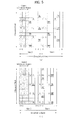
- FIG. 1(a) illustrates the type-1 radio frame structure.
- a downlink radio frame is divided into ten subframes. Each subframe includes two slots in the time domain. The time taken to transmit one subframe is defined as a transmission time interval (TTI).
- TTI transmission time interval
- a subframe may have a duration of 1 ms and one slot may have a duration of 0.5 ms.
- a slot may include a plurality of OFDM symbols in the time domain and includes a plurality of resource blocks (RBs) in the frequency domain. Since 3GPP LTE employs OFDMA for downlink, an OFDM symbol represents one symbol period. An OFDM symbol may be referred to as an SC-FDMA symbol or a symbol period.
- a resource block (RB) which is a resource allocation unit, may include a plurality of consecutive subcarriers in a slot.
- the number of OFDM symbols included in one slot depends on the configuration of a cyclic prefix (CP).
- CPs are divided into an extended CP and a normal CP.
- a slot may include 7 OFDM symbols.
- the duration of each OFDM symbol is extended and thus the number of OFDM symbols included in a slot is smaller than in the case of the normal CP.
- a slot may include, for example, 6 OFDM symbols.
- each slot includes 7 OFDM symbols, and thus each subframe includes 14 OFDM symbols.
- the first two or three OFDM symbols of each subframe may be allocated to a physical downlink control channel (PDCCH) and the other three OFDM symbols may be allocated to a physical downlink shared channel (PDSCH).
- PDCCH physical downlink control channel
- PDSCH physical downlink shared channel
- FIG. 1(b) illustrates the type-2 radio frame structure.
- the type-2 radio frame includes two half frames, each of which has 5 subframes, a downlink pilot time slot (DwPTS), a guard period (GP), and an uplink pilot time slot (UpPTS).
- Each subframe includes two slots.
- the DwPTS is used for initial cell search, synchronization, or channel estimation in a UE
- the UpPTS is used for channel estimation in an eNB and UL transmission synchronization in a UE.
- the GP is provided to eliminate interference taking place in UL due to multipath delay of a DL signal between DL and UL.
- a subframe of the radio frame includes two slots.
- radio frame structures are merely examples, and various modifications may be made to the number of subframes included in a radio frame, the number of slots included in a subframe, or the number of symbols included in a slot.
- FIG. 2 is a diagram illustrating a resource grid for one DL slot.
- a DL slot includes 7 OFDM symbols in the time domain and an RB includes 12 subcarriers in the frequency domain.
- a slot may include 7 OFDM symbols.
- a slot may include 6 OFDM symbols.
- Each element in the resource grid is referred to as a resource element (RE).
- An RB includes 12x7 REs.
- the number NDL of RBs included in a downlink slot depends on a DL transmission bandwidth.
- a UL slot may have the same structure as a DL slot.
- FIG. 3 illustrates a DL subframe structure. Up to the first three OFDM symbols of the first slot in a DL subframe are used as a control region to which control channels are allocated and the other OFDM symbols of the DL subframe are used as a data region to which a PDSCH is allocated.
- DL control channels used in 3GPP LTE include, for example, a physical control format indicator channel (PCFICH), a physical downlink control channel (PDCCH), and a physical hybrid automatic repeat request (HARQ) indicator channel (PHICH).
- PCFICH physical control format indicator channel
- PDCH physical downlink control channel
- HARQ physical hybrid automatic repeat request
- the PHICH carries a HARQ ACK/NACK signal in response to uplink transmission.
- Control information carried on the PDCCH is called downlink control information (DCI).
- the DCI includes UL or DL scheduling information or UL transmission power control commands for UE groups.
- the PDCCH delivers information about resource allocation and a transport format for a DL shared channel (DL-SCH), resource allocation information about a UL shared channel (UL-SCH), paging information of a paging channel (PCH), system information on the DL-SCH, information about resource allocation for a higher-layer control message such as a random access response transmitted on the PDSCH, a set of transmission power control commands for individual UEs of a UE group, transmission power control information, and voice over internet protocol (VoIP) activation information.
- a plurality of PDCCHs may be transmitted in the control region.
- a UE may monitor a plurality of PDCCHs.
- a PDCCH is formed by aggregating one or more consecutive control channel elements (CCEs).
- a CCE is a logical allocation unit used to provide a PDCCH at a coding rate based on the state of a radio channel.
- a CCE corresponds to a plurality of RE groups.
- the format of a PDCCH and the number of available bits for the PDCCH are determined depending on the correlation between the number of CCEs and a coding rate provided by the CCEs.
- An eNB determines the PDCCH format according to DCI transmitted to a UE and adds a cyclic redundancy check (CRC) to the control information.
- the CRC is masked by an identifier (ID) known as a radio network temporary identifier (RNTI) according to the owner or usage of the PDCCH.
- ID identifier
- RNTI radio network temporary identifier
- the PDCCH may be masked by a cell-RNTI (C-RNTI) of the UE. If the PDCCH is for a paging message, the CRC of the PDCCH may be masked by a paging radio network temporary identifier (P-RNTI). If the PDCCH delivers system information, particularly, a system information block (SIB), the CRC thereof may be masked by a system information ID and a system information RNTI (SI-RNTI). To indicate that the PDCCH delivers a random access response in response to a random access preamble transmitted by a UE, the CRC thereof may be masked by a random access-RNTI (RA-RNTI).
- SIB system information block
- SI-RNTI system information RNTI
- RA-RNTI random access-RNTI
- FIG. 4 illustrates a UL subframe structure.
- a UL subframe may be divided into a control region and a data region in the frequency domain.
- a physical uplink control channel (PUCCH) carrying uplink control information is allocated to the control region and a physical uplink shared channel (PUSCH) carrying user data is allocated to the data region.
- PUCCH physical uplink control channel
- PUSCH physical uplink shared channel
- a UE does not simultaneously transmit a PUSCH and a PUCCH.
- a PUCCH for a UE is allocated to an RB pair in a subframe. The RBs of the RB pair occupy different subcarriers in two slots. This is often called frequency hopping of the RB pair allocated to the PUCCH over a slot boundary.
- the packets are transmitted over a radio channel, and therefore signal distortion may occur in the transmission process.
- the received distorted signal should be corrected using channel information.
- a signal which is known to both the transmitter and the receiver is transmitted and the degree of distortion of the signal received over the channel is used to detect the channel information. This signal is referred to as a pilot signal or a reference signal.
- a channel state between a transmit antenna and a receive antenna needs to be identified to receive a correct signal. Accordingly, a separate RS is needed for each transmit antenna and, more particularly, for each antenna port.
- the RSs may be divided into an UL RS and a DL RS.
- the UL RSs include:
- the DL RSs include:
- the RSs may be broadly divided into two reference signals according to the purposes thereof. There are an RS used to acquire channel information and an RS used for data demodulation. Since the former is used when the UE acquires channel information on DL, this RS should be transmitted over a wide band and even a UE which does not receive DL data in a specific subframe should receive the RS. This RS is also applied to situations such as handover.
- the latter RS is sent by the BS along with a resource on DL.
- the UE may receive the RS to perform channel measurement to implement data modulation. This RS should be transmitted in a region in which data is transmitted.
- the CRS is used for acquisition of channel information and for data demodulation, and the UE-specific RS is used only for data demodulation.
- the CRS is transmitted in every subframe in a wide band and RSs for up to four antenna ports are transmitted according to the number of transmit antennas of the BS.
- CRSs for antenna ports #0 and #1 are transmitted. If the number of transmit antennas of the BS is 4, CRSs for antenna ports #0 to #3 are respectively transmitted.
- FIG. 5 is a diagram illustrating a pattern in which CRSs and DRSs defined in a legacy 3GPP LTE system (e.g., Release-8) are mapped to resource block (RB) pairs.
- a downlink RB pair as a unit to which an RS is mapped, may be represented as a unit of one subframe in the time domain times 12 subcarriers in the frequency domain. That is, one RB pair has a length of 14 OFDM symbols for a normal CP ( FIG. 5(a) ) and a length of 12 OFDM symbols for an extended CP ( FIG. 5(b) ).
- FIG. 5 shows locations of RSs on RB pairs in a system in which the BS supports four transmit antennas.
- resource elements denoted by “0", “1", “2” and “3” represent the locations of the CRSs for antenna port indexes 0, 1, 2 and 3, respectively.
- REs denoted by “D” represent locations of the DMRSs.
- CSI-RS Channel State Information-RS
- the CSI-RS which is designed for the LTE-A system supporting up to eight antenna ports on downlink, is a reference signal intended for channel measurement.
- the CSI-RS is different from the CRS which is intended for channel measurement and data demodulation. Accordingly, the CSI-RS does not need to be transmitted in every subframe, unlike the CRS.
- the CSI-RS is used in transmission mode 9, and the DMRS is transmitted for data demodulation.
- the CSI-RS may be transmitted through antenna ports 1, 2, 4, and 8.
- two antenna ports may be antenna ports #15 and #16.
- antenna ports #15 to #18 When eight antenna ports are used, they may be antenna ports #15 to #22.
- a CSI-RS may be generated using Equation 1 given below.
- r l , n s ( m ) denotes a generated CSI-RS
- c ( i ) denotes a pseudo random sequence
- n s denotes the slot number
- l denotes an OFDM symbol
- N RB max denotes the maximum number of RBs of a DL bandwidth.
- the CSI-RS generated through Equation 1 may be mapped to an RE for each antenna port, using Equation 2.
- Equation 2 k' and l' may be determined according to CSI-RS configurations as shown in Table 1.
- mapping to REs is performed for each antenna port.
- FIG. 6 shows mapping of CSI-RSs for each antenna port as described above.
- R0 to R3 respectively represent mapping of CRSs to antenna ports, and the number indications represent mapping of CSI-RSs to antenna ports.
- REs indicated by numbers 0 and 1 represent mapping of a CSI-RS corresponding to antenna port 0 or 1.
- CSI-RSs corresponding to two antenna ports are mapped to the same RE, and may be distinguished by different orthogonal codes.
- the CSI-RS may be transmitted in a specific subframe rather than in every subframe.
- the CSI-RS may refer to CSI-RS subframe configurations as listed in Table 2 given below, and be transmitted in a subframe satisfying Equation 3.
- CSI-RS-SubframeConfig I CSI-RS CSI-RS periodicity T C SI-RS (subframes) CSI-RS subframe offset ⁇ CSI-RS (subframes) 0-4 5 I CSI-RS 5-14 10 I CSI-RS -5 15-34 20 I CSI-RS -15 35-74 40 I CSI-RS -35 75-154 80 I CSI-RS -75 10 ⁇ n f + ⁇ n s / 2 ⁇ - ⁇ CSI - RS ⁇ mod T CSI - RS 0
- T CSI-RS denotes the period for transmission of a CSI-RS
- ⁇ CSI-RS is an offset value
- n f denotes a system frame number
- n s denotes a slot number
- the CSI-RS may be signaled to a UE as a CSI-RS configuration information element, as shown in Table 3.
- 'antennaPortsCount' carries the number (selected among 1, 2, 4, and 8) of antennas through which the CSI-RS is transmitted
- 'resourceConfig' carries an RE in which the CSI-RS is positioned in an RB in time-resource frequency
- 'subframeConfig' carries a subframe in which the CSI-RS is transmitted and a CSI-RS EPRE value for PDSCH EPRE.
- the eNB delivers information about a zero power CSI-RS.
- 'resourceConfig' indicates the position at which the CSI-RS is transmitted. This parameter indicates accurate positions of a symbol and a carrier in an RB according to CSI-RS configuration numbers of Table 1 represented as 0 to 31.
- MIMO schemes may be classified into an open-loop MIMO scheme and a closed-loop MIMO scheme.
- a MIMO transmitter performs MIMO transmission without receiving CSI feedback from a MIMO receiver.
- the MIMO transmitter receives CSI feedback from the MIMO receiver and then performs MIMO transmission.
- each of the transmitter and the receiver may perform beamforming based on CSI to achieve a multiplexing gain of MIMO transmit antennas.
- the transmitter e.g., an eNB
- the transmitter may allocate a UL control channel or a UL-SCH to the receiver.
- the CSI feedback may include a rank indicator (RI), a precoding matrix index (PMI), and a channel quality indicator (CQI).
- RI rank indicator
- PMI precoding matrix index
- CQI channel quality indicator
- the RI is information about a channel rank.
- the channel rank indicates the maximum number of layers (or streams) that may carry different information in the same time-frequency resources. Since the rank is determined mainly according to long-term fading of a channel, the RI may be fed back in a longer period than the PMI and the CQI.
- the PMI is information about a precoding matrix used for transmission of a transmitter and has a value reflecting the spatial characteristics of a channel.
- Precoding refers to mapping transmission layers to transmit antennas.
- a layer-antenna mapping relationship may be determined according to a precoding matrix.
- the PMI is the index of an eNB precoding matrix preferred by the UE based on a metric such as signal-to-interference-plus-noise ratio (SINR), etc.
- SINR signal-to-interference-plus-noise ratio
- the transmitter and the receiver may pre-share a codebook including multiple precoding matrices and only an index indicating a specific precoding matrix in the codebook may be fed back.
- a system supporting an extended antenna configuration e.g. an LTE-A system
- additional acquisition of multi-user (MU)-MIMO diversity using an MU-MIMO scheme is considered.
- MU-MIMO scheme when an eNB performs downlink transmission using CSI fed back by one UE among multiple users, it is necessary to prevent interference with other UEs from occurring because there is an interference channel between UEs multiplexed in the antenna domain. Accordingly, CSI of higher accuracy than CSI in a single-user (SU)-MIMO scheme should be fed back in order to correctly perform MU-MIMO operation.
- SU single-user
- a new CSI feedback scheme may be adopted by modifying conventional CSI including an RI, a PMI, and a CQI so as to more accurately measure and report CSI.
- precoding information fed back by the receiver may be indicated by a combination of two PMIs.
- One of the two PMIs (a first PMI) has a long-term and/or wideband property, and may be referred to as Owl.
- the other PMI (a second PMI) has a short-term and/or subband property, and may be referred to as W2.
- the CQI is information indicating channel quality or channel strength.
- the CQI may be expressed as an index corresponding to a predetermined modulation and coding scheme (MCS) combination. That is, a CQI index that is fed back indicates a corresponding modulation scheme and code rate.
- MCS modulation and coding scheme
- the CQI has a value reflecting a reception SINR that can be achieved when an eNB configures a spatial channel using a PMI.
- the CSI feedback scheme is divided into periodic reporting over a physical uplink control channel (PUCCH) and aperiodic reporting over a PUSCH, which is an uplink data channel, according to a request from an eNB.
- PUCCH physical uplink control channel
- PUSCH aperiodic reporting over a PUSCH, which is an uplink data channel, according to a request from an eNB.
- reporting is configured for UEs by a request bit contained in the UL scheduling information of the eNB.
- each UE Upon receiving this information, each UE sends channel information considering a transmission mode thereof to the eNB over the PUSCH.
- periodic reporting a period of transmission of channel information and a corresponding offset are signaled to each UE in each subframe through a higher layer signal, and the channel information considring a transmission mode of each UE is sent to the eNB over the PUCCH according to a defined period. If data is transmitted on uplink in the subframe in which the channel information is transmitted according to the defined period, the channel information may be transmitted along with the data over the uplink data channel (PUSCH) rather than the PUCCH.
- PUSCH uplink data channel
- the periodic reporting of channel information is described in more detail below.
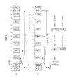
- the periodic reporting is divided into four reporting modes according to CQI and PMI feedback types as shown in Table 4 below.
- the periodic reporting is divided into wideband (WB) CQI and subband (SB) CQI according to CQI feedback types, and is divided into No PMI and single PMI according to whether or not PMI is transmitted.
- Each UE receives information configured by a combination of a transmission period and an offset through RRC signaling in a higher layer. For example, when the UE receives information containing a combination of a period set to '5' and an offset set to '1', the UE transmits channel information in every five subframes as shown in FIG. 7 . In this case, the channel information is transmitted over the PUCCH with a subframe offset placed in the direction in which the subframe index increases from subframe #0.
- subframe indexes are combinations of a system frame number ( n f ) and 20 slot indexes ( n s ; 0 to 19), and thus may be expressed as 10 x n f +floor( n s /2).
- the periodic reporting is divided into one reporting type for transmitting only WB CQI and the other reporting type for transmitting both WB CQI and SB CQI, according to CQI feedback types.
- WB CQI information for the entire band is transmitted in subframes corresponding to each CQI transmission period.
- the transmission period of periodic WB CQI may be set to 2, 5, 10, 16, 20, 32, 40, 64, 80, and 160 ms, or to no transmission.
- PMI needs to be transmitted according to a PMI feedback type in Table 4
- PMI information is transmitted together with CQI.
- WB CQI and SB CQI are alternately transmitted, which will be described with reference to FIG. 8 .
- FIG. 8 shows an exemplary system consisting of 16 RBs.
- the system bandwidth of 16 RBs consists of two bandwidth parts (BPs) (BP0 and BP1), and each BP consists of two subbands (SBs) (SB0 and SB1).
- BPs bandwidth parts
- SBs subbands
- the WB CQI is transmitted in a CQI transmission subframe.
- CQI for one SB having a good channel state from among SB0 and SB1 and an index of this SB are transmitted at BP0.
- CQI for one SB having a good channel state from among SB0 and SB1 at BP1 and an index of the SB having a good channel state are transmitted.
- CQI of individual BPs are sequentially transmitted at BP1.
- CQIs for BPs are sequentially transmitted.
- the CQIs for BPs located between the WB CQI transmitted and the next WB CQI to be transmitted may be sequentially transmitted one to four times. For example, if the CQI for each BP is transmitted once between two WB CQIs, CQIs are sequentially transmitted in the order of WB CQI, BP0 CQI, BP1 CQI, and WB CQI.
- CQIs may be transmitted in the order of WB CQI, BP0 CQI, BP1 CQI, BP0 CQI, BP1 CQI, BP0 CQI, BP1 CQI, BP0 CQI, BP1 CQI, BP0 CQI, BP1 CQI, and WB CQI.
- Information about the number of times of sequential transmission is signaled through a higher layer.
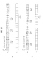
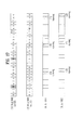
- FIG. 8(b) illustrates CQI transmission when information containing a combination of a period set to '5' and an offset set to '1' is signaled to the UE in the case of transmission of both WB CQI and SB CQI.
- FIG. 8(c) shows RI transmission in addition to CQI transmission of 8(b).
- RI is signaled according to a combination of a transmission period corresponding to a multiple of the WB CQI transmission period and an offset for the transmission period.
- the offset is an offset relative to the CQI transmission offset.
- the offset for RI is defined as 0 or a negative value. For example, if the RI transmission period is one time the WB CQI transmission period, and the offset for RI is '-1', RI is transmitted in a subframe shown in FIG. 8(c) . If the offset for RI is '0' rather than '-1', the transmission subframe of WB CQI overlaps the transmission subframe of RI. In this case, WB CQI is dropped, while RI is transmitted.
- Mode 2-1 in Table 4 two types of periodic reporting may be performed depending on a precoder type indication (PTI) parameter, which is a 1-bit indicator.
- PTI precoder type indication
- W1 and W2 represent the hierarchical codebooks described above.
- a final precoding matrix W is determined by combining W1 and W2 when W1 and W2 are determined.
- N offset,CQI denotes an offset value described above
- N pd denotes a subframe interval between Report 2 or Report 3 and neighboring Report 2 or Report 3.
- Report 2 is transmitted at every H ⁇ Npd interval, and subframes between neighboring Reports 2 are used to transmit Report 3.
- J is the number of BPs
- K, and M have values determined by higher layer signaling.
- M R1 has a value determined by higher layer signaling
- N offset,RI corresponds to an offset value of Report 1.
- FIG. 10 illustrates a heterogeneous network wireless communication system including a macro eNB (MeNB) and micro eNBs (PeNBs or FeNBs).
- MeNB macro eNB
- PeNBs or FeNBs micro eNBs
- the term "heterogeneous network” employed in this specification refers to a network in which an MeNB and a PeNB or FeNB coexist even while they use the same radio access technology (RAT).
- RAT radio access technology
- the MeNB is a normal eNB of a wireless communication system having wide coverage and high transmission power.
- the MeNB may be referred to as a macro cell.
- the PeNB or FeNB may be referred to as, for example, a micro cell, pico cell, femto cell, home eNB (HeNB), relay, etc. (the exemplified PeNB or FeNB and MeNB may be collectively referred to as transmission points (TPs)).
- the PeNB or FeNB a micro version of the MeNB, can independently operate while performing most functions of the MeNB.
- the PeNB or FeNB is a non-overlay type eNB that may be overlaid in an area covered by the MeNB or in a shadow area that is not covered by the MeNB.
- the PeNB or FeNB may cover a smaller number of UEs while having a narrower coverage and lower transmission power than the MeNB.
- a UE (hereinafter, referred to as a macro-UE (MUE)) may be directly served by the MeNB or a UE (hereinafter, referred to as a micro-UE) may be served by the PeNB or FeNB.
- MUE macro-UE
- a UE hereinafter, referred to as a micro-UE
- PeNB UE
- FeNB UE
- a PUE present in the coverage of the MeNB may be served by the MeNB.
- PeNBs or FeNBs may be classified into two types according to whether UE access is limited.
- the first type is an open access subscriber group (OSG) or non-closed access subscriber group (non-CSG) eNB and corresponds to a cell that allows access of the existing MUE or a PUE of a different PeNB.
- the existing MUE can handover to the OSG type eNB.
- the second type is a CSG eNB which does not allow access of the existing MUE or a PUE of a different PeNB. Accordingly, handover to the CSG eNB is impossible.
- CoMP transmission and reception technology also called co-MIMO, collaborative MIMO or network MIMO
- the CoMP technology may increase the performance of UEs located at a cell edge and the average sector throughput.
- the performance of a UE located at a cell edge and average sector throughput may be lowered due to inter-cell interference (ICI).
- ICI inter-cell interference
- the legacy LTE/LTE-A system has adopted a simple passive technique such as fractional frequency reuse (FFR) based on UE-specific power control such that a UE located at a cell edge may have appropriate throughput performance in an environment constrained by interference.
- FFR fractional frequency reuse
- attenuating the ICI or reusing ICI as a desired signal for the UE may be more desirable than lowering use of frequency resources per cell.
- a CoMP transmission technique may be employed.
- CoMP schemes applicable to downlink may be broadly classified into joint processing (JP) and coordinated scheduling/beamforming (CS/CB).
- JP joint processing
- CS/CB coordinated scheduling/beamforming
- the CoMP cooperation unit refers to a set of eNBs used for a CoMP transmission scheme.
- the JP scheme may be further divided into joint transmission and dynamic cell selection.
- Joint transmission refers to a technique of simultaneously transmitting PDSCHs from a plurality of transmission points (a part or the entirety of a CoMP cooperation unit). That is, a plurality of transmission points may simultaneously transmit data to a single UE. With the joint transmission scheme, the quality of a received signal may be coherently or non-coherently improved, and interference with other UEs may be actively eliminated.
- Dynamic cell selection is a technique of transmitting a PDSCH from one transmission point (of a CoMP cooperation unit) at a time. That is, one transmission point transmits data to a single UE at a given time point, while the other transmission points in the CoMP cooperation unit do not transmit data to the UE at the time point.
- a transmission point to transmit data to a UE may be dynamically selected.
- CoMP cooperation units may cooperatively perform beamforming for data transmission to a single UE. While data is transmitted to the UE only from a serving cell, user scheduling/beamforming may be determined through coordination of cells of the CoMP cooperation units.
- CoMP reception refers to reception of a signal transmitted through cooperation among a plurality of geographically separated transmission points.
- CoMP schemes applicable to uplink may be classified into joint reception (JR) and coordinated scheduling/beamforming (CS/CB).
- the JR scheme indicates that a plurality of reception points receives a signal transmitted through a PUSCH.
- the CS/CB scheme indicates that only one point receives a PUSCH, and user scheduling/beamforming is determined by coordination of the cells of the CoMP unit.
- multi-cell base stations may jointly support data for a UE.
- the base stations may simultaneously support one or more UEs using the same radio frequency resources, thereby increasing system performance.
- a base station may perform space division multiple access (SDMA) based on CSI between the UE and the base station.
- SDMA space division multiple access
- a serving eNB and one or more cooperative eNBs are connected to a scheduler over a backbone network.
- the scheduler may receive channel information about the channel states between each UE and cooperative eNBs measured and fed back by the cooperative eNBs over the backbone network, and operate based on the channel information. For example, the scheduler may schedule information for a cooperative MIMO operation for the serving eNB and the one or more cooperative eNBs. That is, the scheduler may directly give each eNB a command to perform the cooperative MIMO operation.
- the CoMP system operates as a virtual MIMO system by grouping a plurality of cells into one group.
- the CoMP system may adopt a MIMO communication scheme employing multiple antennas.
- FIG. 11 illustrates a CoMP cluster.
- a CoMP cluster refers to a CoMP cooperation unit mentioned above.
- FIG. 11 (a) illustrates a case in which cells in a CoMP cluster use different physical cell IDs (PCIDs)
- FIG. 11(b) illustrates a case in which cells in a CoMP cluster use the same PCID.
- the CoMP clusters may use different PCIDs, and the cells in a single cluster may be configured in the form of a distributed antenna of an eNB or an RRH by sharing a PCID.
- some of the cells in a cluster may share a PCID.
- all the cells having the same PCID may transmit a common signal such as a primary synchronization signal (PSS)/secondary synchronization signal (SSS), a CRS, a PBCH, or a CRS-based PDCCH/PDSCH at the same time.
- PSS primary synchronization signal
- SSS secondary synchronization signal
- CRS CRS
- PBCH PBCH
- CRS-based PDCCH/PDSCH CRS-based PDCCH/PDSCH
- some cells having higher transmission power than may transmit a common signal among the cells having the same PCID, and the other cells may not transmit a common signal.
- each cell may individually perform transmission, and have a cell splitting gain.
- one or more CSI processes per serving cell may be configured for a UE.
- a plurality of CSI processes associated with a channel measurement-related CSI-RS resource configuration and an interference measurement-related CSI-IM (Interference Measurement) resource configuration may be configured for a UE.
- CSI-RS resource configuration may correspond to either a case in which subframes have the same channel characteristics or a case in which subframes have different/variable channel characteristics.
- the former may be referred to as a periodic CSI-RS, continuous CSI-RS, or fixed beam CSI-RS, and the latter may be referred to as an aperiodic CSI-RS, instantaneous CSI-RS, or adaptive beam CSI-RS.
- a CSI-IM resource (or interference measurement resource (IMR)) configuration may correspond to either a case in which subframes have the same channel characteristics or a case in which subframes have different/variable channel characteristics.
- the former may be referred to as a periodic IMR, continuous IMR, fixed beam IMR or fixed property IMR, and the latter may be referred to as an aperiodic IMR, instantaneous IMR, adaptive beam IMR or adaptive property IMR.
- a periodic CSI-RS/IMR and a aperiodic CSI-RS/IMR may be distinguished from each other according to whether subframes have the same channel/interference characteristics or different/variable channel/interference characteristics.
- the different/variable channel/interference characteristics may mean that an antenna virtualization matrix is not constantly maintained in a subframe corresponding to each configuration in 3D MIMO or massive MIMO.
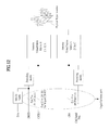
- 3D MIMO and antenna virtualization matrices related to one embodiment of the present invention will be described with reference to FIG. 12 .
- the number of transmit antennas increases for 3D MIMO in the pattern of 16 ports, 32 ports, 64 ports, and the like, the number of REs used for CSI-RS transmission for CSI measurement significantly increases, resulting in increase of overhead.
- 64 REs are needed among 168 REs of a subframe, which means 38% of resources are needed for CSI-RS transmission. This is a significant overhead even if it is considered that the CSI-RS is not transmitted in every subframe.
- CSI-RS-associated overhead may significantly increase. This problem may be solved by multiple antenna virtualization matrices.
- CSI-RSs for M ports among N ports may be UE-specifically and aperiodically transmitted, which is a variation of cell-specific and periodic transmission of the CSI-RSs for N ports in resources corresponding to one CSI-RS configuration (Herein, M, which is less than or equal to N, may be differently configured for each UE and vary with time for a specific UE).
- M which is less than or equal to N, may be differently configured for each UE and vary with time for a specific UE.
- M antenna ports may be selected and used among N antenna ports, or mapping between CSI-RSs of N antenna ports and M UE-specific ports or antenna virtualization may be performed using a transform matrix B of N*M dimensions.
- FIG. 12 conceptually shows such antenna virtualization.
- a CSI-RS uses M antenna ports, and the CRS uses C antenna ports.
- N by M antenna virtualization matrix B is used for CSI-RS transmission, the matrix may be designated/configured for each UE.
- antenna virtualization matrix A used for CRS transmission is preferably intended for all UEs.
- z i denotes a precoding vector for the i-th CSI-RS antenna port.
- transmit signals of the respective antennas may be transmitted by applying different time delays ( ⁇ N , ⁇ C ) as in Equation 4 below in order to frequency-selectively apply antenna virtualization.
- the antenna virtualization matrix B is preferably configured so as to maximize the energy of the signal received by a corresponding UE, and may vary depending on the location of the UE. Such antenna virtualization matrix B may be found through an uplink SRS (based on reciprocity of downlink and uplink channels). An SRS and previously reported CSI feedback information may be used to trace an optimum antenna virtualization matrix B according to change of location of the UE and change in the channel environment.
- the antenna virtualization matrix may be UE-group-specifically used. Specifically, for a group of UEs at similar positions, a representative antenna virtualization matrix B may be selected, UEs of the group may be simultaneously informed of transmission of a CSI-RS, and CSI may be fed back.
- the CSI-RS transmission time and period of K antenna group may be determined according to the number of active UEs designated for the corresponding antenna group and the channel change rate for the corresponding UEs.
- transmission overhead if the antenna group does not include any active UE, the eNB may not transmit the CSI-RS of the antenna group.
- grouping may be implemented through an N by M transform matrix B as shown in FIG. 12 .
- antenna virtualization of N antenna ports and the k-th M port antenna group may be performed through a transform matrix B k .
- Matrix B k1 for the k1-th M-port antenna group and matrix B k2 for the k2-th M-port antenna group are preferably configured to satisfy Equation 4 below, i.e., to be orthogonal to each other.
- B k ⁇ 1 T ⁇ B k ⁇ 2 0
- the eNB may let a specific UE report an average receive signal level, i.e., RSRP for each antenna port group to determine an antenna port group suitable to be allocated to the UE.
- the eNB may configure a CSI-RS management set including multiple periodic CSI-RS transmissions, where the respective CSI-RS in the set represent the antenna port group, such that the UE can report RSRP for multiple CSI-RS configurations.
- the number of antenna ports in an antenna group may be individually set for each group.
- the eNB establishes K CSI-RS transmission configurations and assigns an antenna virtualization matrix B k to each configuration such that a CSI-RS virtualized through a corresponding matrix is transmitted.
- the eNB may inform the UEs of only some CSI-RS transmission configurations efficient for the UEs among K CSI-RS transmission configurations based on the SRS reception state and an RSRP report.
- the periodic CSI-RS/IMR may mean that the antenna virtualization matrix B k does not change in the subframes corresponding to the CSI-RS/IMR resource configuration. That is, as shown in FIG. 13(a) , B k1 for periodic CSI-RS configuration 1 does not change in the subframes corresponding to CSI-RS configuration 1, and B k2 for periodic CSI-RS configuration 2 does not change in the subframes corresponding to CSI-RS configuration 2.
- the aperiodic CSI-RS/IMR may means that the virtualization matrix B k changes in subframes corresponding to a resource configuration as shown in FIG. 13(b) .
- a CSI-RS configuration and channel measurement in a CSI-RS resource.
- description will be mainly given of an aperiodic CSI-RS configuration (which means that subframes corresponding to a CSI-RS resource configuration according to change of the antenna virtualization matrix have different/variable channel characteristics, as described above).
- An eNB may designate a resource region in which a CSI-RS can be transmitted through a cell-specific CSI-RS configuration.
- the eNB may be used to inform the UE that the PDSCH is not transmitted in the resource region in which a CSI-RS can be transmitted.
- the resource region designated through the cell-specific CSI-RS configuration may be divided and used for non-zero power CSI-RS transmission for CSI measurement, for a zero-power CSI-RS configured so as not to interfere with a CSI-RS of a neighboring cell, and/or as an IMR for interference measurement.
- a cell-specific CSI-RS configuration may include parameters such as subframeConfig, ResourceConfigList, zeroTxPowerResourceConfigList, and zeroTxPowerSubframeConfig.
- the parameter subframeConfig may indicate a subframe period and a offset by which the CSI-RS is transmitted
- the parameter ResourceConfigList may indicate, through a k-bit bitmap, whether or not k resource regions allowing for transmission of x port CSI-RS in a subframe are configured as cell-specific CSI-RS resources.
- the eNB may designate, through one or more UE-specific aperiodic CSI-RS configurations, a CSI-RS transmission-enabled region for the UE.
- a UE-specific aperiodic CSI-RS transmission resource may be a subset of a cell-specific CSI-RS resource, as shown in FIG. 14 . If the UE-specific aperiodic CSI-RS is not a subset of a cell-specific CSI-RS, the UE may determine that this is an RRC signaling error, and ignore the UE-specific aperiodic CSI-RS configuration or assume that the PDSCH is not mapped to the UE-specific aperiodic CSI-RS resource.
- the UE-specific aperiodic CSI-RS configuration may include parameters antennaPortsCount, subframeConfig, resourceConfig, and p-C.
- the parameter antennaPortsCount defines the number of antenna ports configured for the corresponding UE
- the parameter subframeConfig defines a subframe period and an offset by which the CSI-RS is transmitted
- the parameter resourceConfig indicates the position of a CSI-RS transmission RE in a subframe
- the parameter p-C indicates a ratio between the PDSCH transmit power and the CSI-RS transmit power.
- channel measurement for corresponding CSI reporting of the UE may be performed as follows.
- the CSI-RS is not necessarily transmitted through a subframe in which transmission of the CSI-RS is enabled. Further, even if the CSI-RS is transmitted through contiguous subframes, the subframes may have different antenna virtualization matrices of the CSI-RS for the UE. Accordingly, interpolation of the CSI-RS is not performed over contiguous CSI-RS transmission subframes in the process of channel estimation. In other words, in the case of a UE-specific aperiodic CSI-RS configuration, channel estimation may be performed only in a corresponding CSI-RS transmission subframe. Referring to FIG.
- the UE uses, in performing channel measurement, CSI-RS in subframes prior to the subframe in which CSI reporting is to be performed, as shown in FIG. 15(a) .
- the UE uses, in performing channel measurement, only the CSI-RS in a subframe immediately before the subframe in which CSI reporting is to be performed, as shown in FIG. 15(b) .
- the eNB delivers a CSI-RS configuration to the UE, it may also inform of whether the configuration is a periodic configuration or an aperiodic configuration.
- the eNB when the eNB delivers a CSI-RS configuration or a CSI reporting configuration to the UE, it may also inform the UE of whether or not channel estimation results from multiple CSI-RS transmission subframes can be combined for generation of CSI. More specifically, the eNB may inform the UE of the number of previous CSI-RS transmission subframes providing channel estimation results which can be combined for generation of CSI.
- the number of CSI-RS transmission subframes which can be used for CSI generation may be defined as a CSI measurement window. If the CSI measurement window is 1, the UE can use only the channel estimation result from a single CSI-RS transmission subframe to perform CSI generation.
- the UE combines, when assigned a periodic CSI-RS, channel estimation results from multiple CSI-RS transmission subframes to generate CSI, while the UE generates, when assigned an aperiodic CSI-RS, CSI in each individual CSI-RS transmission subframe.
- multi-shot/M-shot aperiodic CSI-RS transmission may be considered.
- M-shot may refer to the number of CSI-RSs transmitted with the same channel characteristics in transmitting aperiodic CSI-RSs.
- it may mean that an antenna virtualization matrix is maintained in M subframes.
- the UE perform channel measurement using CSI-RSs transmitted in two subframes prior to the subfrme in which CSI reporting is to be performed.
- the two subframes needs to be subfames included in the aperiodic CSI-RS configuration.
- FIG. 16 illustrates an example of 2-shot aperiodic CSI-RS transmission.
- FIG. 16(a) illustrates a case where subframes in which an antenna virtualization matrix is maintained are spaced a certain offset from each other
- FIG. 16(b) illustrates a case where subframes in which an antenna virtualization matrix is maintained neighbor each other.
- the eNB needs to inform of an offset value in addition to the value of M and the starting position of a CSI-RS group, compared to the case of FIG. 16(b) .
- FIG. 16 illustrates an example of 2-shot aperiodic CSI-RS transmission.
- FIG. 16(a) illustrates a case where subframes in which an antenna virtualization matrix is maintained are spaced a certain offset from each other
- FIG. 16(b) illustrates a case where subframes in which an antenna virtualization matrix is maintained neighbor each other.
- the eNB needs to inform of an offset value in addition to the value of M and the starting position of a CSI-RS
- the UE may use the CSI-RS of the 24th subframe to determine the CSI reported in the 28th subframe.
- the UE since the UE has not recognized all the CSI-RSs belonging to CSI-RS group 3, accuracy of CSI estimation becomes low. Accordingly, in order for the UE to determine the CSI reported in the 28th subframe, the UE may use CSI-RSs of the 14th and 19th subfames, which belong to the CSI-RS group 2, to estimate the CSI.
- the CSI information that is fed back when the UE feeds back an aperiodic CSI report over the PUSCH at time n is based on an aperiodic CSI-RS of the UE-specific aperiodic CSI-RS transmission subframe that is recently received at or before time (n-k2) and the CSI-RSs in the CSI-RS group to which the received CSI-RS belongs.
- the CSI information that is fed back when the UE feeds back an aperiodic CSI report over the PUSCH at time n may be based on all the aperiodic CSI-RS in a CSI-RS group for which reception has been recently completed at or before (n-k2).
- the eNB may designate a method that is to be used between these two methods.
- a scheme of periodic reporting over the PUCCH or a scheme of aperiodic reporting over the PUSCH may be used.
- a periodic CSI-RS transmission configuration for periodic CSI reporting over the PUCCH and an aperiodic CSI-RS transmission configuration for aperiodic CSI reporting over the PUSCH may be individually set for the UE by the eNB.
- the CSI for periodic CSI reporting may be based on combined channel estimation
- the CSI for aperiodic CSI reporting may be based on a result estimated in a specific subframe.
- channel estimation for periodic CSI reporting over the PUCCH may be performed based on CRSs, and channel estimation for aperiodic CSI reporting over the PUSCH may be based on CSI-RSs which are aperiodically transmitted.
- the eNB may determine an MCS of a CRS-based PDSCH/PDCCH for the UE through periodic CSI reporting over the PUCCH.
- each CSI-RS transmission configuration may be a periodic configuration or an aperiodic configuration.
- a Periodic CSI-RS transmission configuration may be used for both periodic CSI reporting over the PUCCH and aperiodic CSI reporting over the PUSCH, and an aperiodic CSI-RS transmission configuration may be used only for aperiodic CSI reporting over the PUSCH.
- the eNB ensures that a CSI-RS for channel measurement becomes a periodic CSI-RS transmission configuration, in configuring the scheme of periodic CSI reporting over the PUCCH.
- the eNB may deliver multiple CSI-RS transmission configurations to the UE and designate a CSI measurement window for each CSI-RS transmission configuration.
- a CSI-RS transmission configuration having a CSI measurement window greater than 1 may be used for both the scheme of periodic CSI reporting over the PUCCH and the scheme of aperiodic CSI reporting over the PUSCH, and a CSI-RS transmission configuration having a measurement window equal to 1 may be used only for the scheme of aperiodic CSI reporting over the PUSCH.
- the eNB ensures that a CSI-RS for channel measurement has a CSI measurement window greater than 1 in configuring the scheme of periodic CSI reporting over the PUCCH.
- the size of the cell-specific CSI-RS resource may be variably managed depending on the number of CSI-RS transmissions which is determined according to the number of active UEs, positions and distribution of the UEs, and a channel change rate. Specifically, the size of the cell-specific CSI-RS resource may be increased when the number of aperiodic CSI-RS transmissions increase, and may be reduced when the number of aperiodic CSI-RS transmissions decreases. To change the size of the cell-specific CSI-RS resource, the cell-specific CSI-RS configuration needs to be re-set. In this case, RRC signaling overhead and/or delay occurs.
- the eNB may pre-inform of a position where an aperiodic CSI-RS can be transmitted through the cell-specific CSI-RS configuration, and dynamically indicate, over the PDCCH, whether a CSI-RS is transmitted or a PDSCH is transmitted at the position.
- the eNB designate a cell-specific aperiodic CSI-RS configuration and a UE-specific aperiodic CSI-RS configuration and inform the UE of the same, the eNB make it sure that the resource of the UE-specific aperiodic CSI-RS configuration becomes a subset of the resource of the cell-specific aperiodic CSI-RS configuration.
- the UE is informed, through a 'CSI-RS exist field' of the DCI, whether or not a CSI-RS and a PDSCH are transmitted together in a corresponding subframe.
- the UE is informed that the PDSCH is not transmitted in an RE designated for the cell-specific aperiodic CSI-RS configuration.
- positions of REs where CSI-RS transmission is allowed may be designated by a unit of X REs up to Z, and Z bits may be allocated to the 'CSI-RS exist field' of the DCI to inform of whether or not REs are used for CSI-RS transmission or PDSCH transmission for every X REs.
- the 'CSI-RS exist field' may be added to the DCI.
- the 'CSI-RS exist field' may be omitted from the DCI.
- the length of DCI transmitted in a CSI-RS transmission-available subframe indicated through the cell-specific aperiodic CSI-RS configuration and a subframe that is not indicated through the cell-specific aperiodic CSI-RS configuration may be different depending on whether or not the 'CSI-RS exist field' is present.
- the DCI When the DCI is transmitted over the ePDCCH, there is a possibility of collision between the DCI transmission and CSI-RS transmission. Accordingly, when the ePDCCH is received in the CSI-RS transmission-available subframe indicated through the cell-specific aperiodic CSI-RS configuration, it may be assumed/expected/set that the ePDCCH is never mapped to the CSI-RS transmission-available region. However, in the case which the PDSCH is received through the DCI delivered over the ePDCCH, whether or not the PDSCH is mapped to the CSI-RS transmission-available region is determined through the 'CSI-RS exist field' of the DCI.
- only an aperiodic CSI-RS configuration may be designated for the UE without dividing the configurations into a cell-specific aperiodic CSI-RS configuration and a UE-specific aperiodic CSI-RS configuration.
- only an aperiodic CSI-RS configuration is designated for the UE, and whether or not CSI-RS transmission is performed in the resource is determined through the DCI and the uplink DCI.
- Whether to transmit a CSI-RS or a PDSCH on a resource corresponding to the subframe designated for transmission of an aperiodic CSI-RS through the aperiodic CSI-RS configuration is indicated through a specific indicator of the DCI. If the CSI-RS is transmitted on the resource, whether to measure and report the CSI is indicated through the uplink DCI.
- multiple UE-specific aperiodic CSI-RS configurations may be set for the UE.
- the number of antenna ports for each of the configurations may be differently set. This is intended to allow the UE to use a different number of antenna ports to perform aperiodic CSI reporting depending on the time.
- the antenna virtualization matrix B needs to be properly changed according to change in the location of the UE and the surrounding environment.
- Each of the multiple CSI-RS configurations allocated to the UE indicates whether the corresponding CSI-RS is a periodic CSI-RS or an aperiodic CSI-RS.
- the configured transmission resources for the periodic CSI-RSs should serve as unique resources rather than overlapping other CSI-RS transmission resourced.
- the aperiodic CSI-RSs may share transmission resources.
- transmission resources for 4-port aperiodic CSI-RSs may be configured to be a part of 8-port aperiodic CSI-RS transmission resources. In other words, the eNB uses half of the 8-port aperiodic CSI-RS transmission resources to transmit 4-port aperiodic CSI-RSs to the UE.
- the CSI reporting modes may include a wideband reporting mode, a subband reporting mode, a UE-selective reporting mode. This is intended to allow the UE to alternately use the wideband reporting mode and the subband reporting mode according to a situation to perform aperiodic CSI reporting.
- the eNB may select an approximate beam direction by making a request for wideband CSI reporting to the UE, and then transmit a CSI-RS in the beam direction and make a request for subband CSI reporting.
- multiple CSI-RS configurations including aperiodic CSI-RS configurations and periodic CSI-RS configurations may be allocated to the UE.
- multiple CSI-RS configurations may be assigned to the UE and the UE may be informed whether each CSI-RS configuration is for periodic CSI-RS transmission or for aperiodic CSI-RS transmission.
- configuration parameters such as antennaPortsCount, resourceConfig, subframeConfig and p-C may be independently set for each aperiodic CSI-RS configuration.
- the 'CSI request field' included in the uplink DCI for requesting aperiodic CSI reporting may be constructed with multiple bits to indicate a CSI-RS configuration for which CSI reporting is requested.
- the eNB may designate multiple aperiodic CSI-RS configurations such that each configuration designates a different subframe as a CSI-RS transmission-available subframe, and the UE may conform to the number of antenna ports for a configuration to which a UE-specific CSI-RS recently received at or before time n belongs, with respect to 'CSI request' of subframe time n.
- a single aperiodic CSI-RS configuration may be divided into multiple subframe sets and designate the number of antenna ports for each of the subframe sets.
- IMRs may be configured for the UE together with or independently of the CSI-RS resource configurations described above, and the eNB may inform the UE of the IMRs through an IMR resource configuration/an IMR configuration.
- IMRs may include a periodic IMR and an aperiodic IMR, similar to the case of CSI-RSs described above.
- description will be given of elements of an IMR configuration, and an aperiodic IMR configuration and interference measurement according to one embodiment of the present invention.
- An IMR configuration may include parameters subframeConfig and resourceConfig.
- the parameter subframeConfig defines the period and offset of subframes in which interference measurement resources are configured, and the parameter resourceConfig indicates the position of an interference measurement RE in a subframe.
- the UE uses only designated IMRs to perform interference measurement, considering signals received on the resources indicated by an IMR configuration as interference.
- Periodic IMR configuration means that an interference environment is uniform among the subframe according to the IMR configuration
- aperiodic IMR configuration means that the subframes according to the IMR configuration have different interference environments. Accordingly, in the case of the periodic IMR configuration, the UE may measure and combine/average interferences over contiguous IMR configuration subframes. In the case of the aperiodic IMR, the subframes may have different interference characteristics, and thus the interference measured in a subframe closest to a subframe for performing CSI reporting measurement may be used for CQI reporting.
- the eNB may directly inform the UE of whether interference estimation results from multiple previous IMR transmission subframes can be combined for interference estimation or only the interference estimation result from a recent IMR transmission subframe should be used, when the eNB delivers an IMR configuration to the UE.
- the eNB may also inform the UE of the number of recent IMR transmission subframes providing interference estimation results to be combined. In this case, the number of indicated subframes may be referred to as an interference measurement window.
- An eNB performing MU-MIMO scheduling may use an aperiodic IMR to accurately receive CSI from MU-MIMO-paired UEs.
- An eNB is configured to configure a periodic IMR for the UEs and the UEs are configured to report CSI about the SU-MIMO state.
- the eNB determines UEs to be subject to be MU-MIMO-paired based on the SU-MIMO CSI that is fed back.
- the fed-back PMI indicating a channel direction is selected from a restricted codebook in consideration of feedback overhead, the channel direction may not be accurately indicated.
- the eNB may configure an aperiodic IMR for UEs, and transmit designated signals to the MU-MIMO-paired UEs on the IMR in a specific subframe such that CQI and CSI to be used later in MU-MIMO scheduling are reported.
- the eNB may determine to apply MU-MIMO pairing to UE 1 and UE 2 and receive CSI from the UEs.
- the eNB may transmit a signal for UE 2 that is MU-MIMO paired on an RE of the third subframe which is the IMR of UE 1.
- the signal for UE 2 may be PDSCH for UE 2 or a dummy data signal subjected to a PMI to be used for later transmission to UE 2.
- UE 1 may measure each channel and interference through the CSI-RS and IMR of the third subframe, calculate CSI based on the same, and then perform CSI reporting in the eighth subframe.
- the eNB may transmit a signal for UE 1 in the IMR for UE 2 (the fourth subframe) and cause corresponding CSI to be reported.
- the eNB may revise transmission AMC and PMI to be used in performing MU-MIMO scheduling of UE 1 and UE 2.
- the eNB may perform an operation for MU-MIMO in the second radio frame as in the first radio frame, as shown in FIG. 17 .
- the IMR for CSI measurement intended for MU-MIMO needs to have an interference measurement window set to 1 so as not to perform inter-subframe averaging.
- the UE is assigned one or more periodic IMRs and one or more aperiodic IMRs, the periodic IMR is used to receive CSI for SU-MIMO, and the aperiodic IMR used to receive CSI for MU-MIMO.
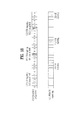
- FIG. 18 illustrates a case in which the same IMR configuration is designated for the MU-MIMO paired UEs.
- the eNB may transmit a signal for UE 2 on the IMR of the third subframe and instruct UE 1 to report CSI in the eight subframe using the IMR. Then, the eNB may transmit a signal for UE 1 on the IMR of the thirteenth subframe based on the CSI information and instruct UE 2 to report CSI in the eighteenth subframe using the IMR.
- aperiodic reporting may be more suitable as a CSI feedback method than periodic reporting.
- the eNB may configure an aperiodic IMR for a specific UE and make a request for CSI feedback to the UE through the 'CSI request field' of the DCI of PDCCH.
- the UE may feed back an aperiodic CSI report over the PUSCH in subframe (n+k).
- the fed-back CSI information is information measured based on an IMR of a recent subframe configured at or before subframe time n.
- the UE when the UE receives an aperiodic CSI request over the PDCCH at the time of subframe (n-k1), the UE feeds back an aperiodic CSI report through the PUSCH at time n.
- the fed-back CSI information is measured based on a recent subframe at or before time (n-k2).
- an M-shot (multi-shot) aperiodic IMR may be considered as in the case of an aperiodic IMR.
- the eNB transmits the same interference signal on the IMRs over the M contiguous IMR configuration subframes such that the UE can estimate the same interference. That is, M contiguous IMR configuration subframes are grouped into one.
- the eNB additionally informs the UE of the value of M and an offset value of the starting position of the IMR group.
- a multi-shot aperiodic IMR scheme In terms of a multi-shot aperiodic IMR scheme, according to a first method for designating an IMR to be measured, when the UE feeds back an aperiodic CSI report over the PUSCH at time n, the fed-back CSI information is measured based on a recent IMR configuration subframe at or before time (n-k2) and other IMRs in the IMR group to which the IMR belongs.
- a second method when the UE feeds back an aperiodic CSI report over the PUSCH at time n, the fed-back CSI information is measured based on all the IMRs in a IMR group in which reception has been recently completed at or before time (n-k2).
- the eNB may designate either the first method or the second method that is to be sued by the UE.
- transmission subframes of IMRs belonging to an IMR group may be defined as neighboring subframes.
- the eNB informs the UE of an interval of IMR group configurations and the value of M.
- a plurality of CSI processes may be configured for a UE, and the UE may determine and report CSI about one of the CSI processes.
- the CSI processes may be related to (a combination of) a CSI-RS configuration for channel measurement and a CSI-IM configuration for interference measurement.
- the CSI-RS configuration may be the periodic CSI-RS configuration or aperiodic CSI-RS configuration described above, and the CSI-IM configuration may also be the periodic or aperiodic CSI-RS configuration described above.
- the UE may measure a channel based on a CSI-RS resource corresponding to a CSI process, and interference based on a CSI-IM resource corresponding to the CSI process.
- a codebook for CSI reporting that is used in determining the CSI may be one of two or more codebooks independently corresponding to multiple CSI processes configured for the UE. For example, referring to FIG. 19 , when there are two codebooks (codebooks #1 and #2) and three CSI processes (CSI processes #1, #2 and #3) that reflect different beams/antenna characteristics, the codebooks may be individually designated for the respective CSI processes.
- codebook #1, codebook #2 and codebook #3 may be individually/independently designated/allocated/mapped to CSI process #1, CSI process #2 and CSI process #3.
- codebooks #1 and #2 may be pre-configured for different beams/antenna characteristics.
- a CSI-RS of a narrow beam may be transmitted after a CSI-RS of a wide beam is transmitted and thereby the beam directionality is confirmed.
- a CSI-RS of a wide beam may be transmitted to feed back CSI.
- a transmission channel of a CSI-RS virtualized by a matrix having the characteristics of the wide beam may be well represented by a codebook reflecting the characteristics of the wide beam
- a CSI-RS transmission channel virtualized by a matrix having the characteristics of a narrow beam may be well represented by a codebook reflecting the characteristics of the narrow beam. Accordingly, when multiple codebooks are used to well represent multiple channel environments, codebooks to be used for CSI processes configured for the UE are individually designated. Alternatively, codebooks to be used are individually designated for multiple CSI-RS configurations set for the UE. For example, the eNB allocates two CSI-RS configurations to the UE, and designate a different codebook for each of the CSI-RS configurations.
- the eNB connects codebook #1 reflecting the characteristics of a wide beam to CSI-RS configuration 1 and codebook #2 reflecting the characteristics of a narrow beam to CSI-RS configuration 2 and inform the UE of this information. Then, the eNB transmits a CSI-RS of a wide beam to the UE through CSI-RS configuration 1 and instructs the UE to measure this and report CSI using codebook #1. In contrast, the eNB transmits a CSI-RS of a narrow beam through CSI-RS configuration 2 set for the UE and instructs the UE to measure this and report CSI using codebook #2.
- An eNB may allocate multiple CSI-RS configurations and multiple IMR configurations to the UE and individually indicate whether each configuration is a periodic configuration or an aperiodic configuration.
- the eNB may allocate multiple CSI-RS configurations and multiple IMR configurations to the UE and inform the UE of the size of a window for measurement of each configuration on a subframe-by-subframe basis. If a CSI measurement window designated for a specific CSI-RS configuration is 1, the UE uses only a channel estimation result from a single CSI-RS transmission subframe to generate CSI. Similarly, if an interference measurement window designated for a specific IMR configuration is 1, the UE uses an estimation result from a single IMR subframe to determine an estimated value of interference (or a correlation between an interference direction and interference).
- a specific CSI (reporting) process is generated by designating one CSI-RS configuration for receive signal measurement and one IMR configuration for interference measurement.
- Both connected CSI-RS configuration and IMR configuration may be aperiodic configurations or periodic configurations.
- an aperiodic CSI-RS configuration and a periodic IMR configuration may be connected to generate a CSI reporting process.
- a periodic CSI-RS configuration and a aperiodic IMR configuration may be connected to generate a CSI reporting process.
- Table 5 below exemplarily shows four possible types of CSI process according to combinations of whether or not the CSI-RS is periodic/aperiodic and whether or not the IMR is periodic/aperiodic. Only some of these processes may be supported and pre-designated. For example, only the PP CSI process and the AA CSI process may be supported. In the case in which only the PP CSI process and the AA CSI process are supported, the eNB may designate whether each CSI process is of PP type or AA type when it informs the UE of the CSI processes. Alternatively, the eNB may inform the UE of measurement windows for the CSI processes on the subframe-by-subframe basis. In this case, the same value of the measurement window is used for both CSI measurement and interference measurement.
- Periodic IMR Continuous IMR
- Aperiodic IMR Instantaneous IMR
- Periodic CSI-RS Continuous CSI-RS
- PA PA
- Aperiodic CSI-RS Instantaneous CSI-RS
- AP CSI process
- AA CSI process
- subframeConfig of an aperiodic CSI-RS configuration is identical to subframeConfig of a aperiodic IMR configuration may be supported.
- 1IMR is set to be always present in a CSI-RS transmission subframe.
- aperiodic reporting is more suitable than periodic reporting as a CSI feedback scheme.
- the eNB configures aperiodic CSI-RS transmission and an aperiodic IMR for a specific UE and makes a request to the UE for CSI feedback through 'CSI request field' in the DCI of the PDCCH.
- the UE may feed back an aperiodic CSI report over the PUSCH in time (n+k).
- the fed-back CSI information is measured based on only an aperiodic CSI-RS recently received and an aperiodic IMR recently configured at or before subframe time n.
- the UE when the UE receives an aperiodic CSI request over the PDCCH at subframe time (n-k1), the UE feeds back an aperiodic CSI report through the PUSCH at time n.
- the fed-back CSI information is measured based on only an aperiodic CSI-RS recently received and an aperiodic IMR recently configured at or before subframe time (n-k2).
- Table 6 below shows possible combinations of CSI process types and CSI reporting modes. Only some of the combinations may be supported and pre-designated.
- the AA CSI process may be designated to support only aperiodic PUSCH CSI reporting.
- the PA CSI process and the AP CSI process may also be designated to support only aperiodic PUSCH CSI reporting. Only some CSI reporting modes may be supportable.
- the AA CSI process, and the PA CSI process or the AP CSI process may be supported in the wideband reporting mode among the periodic PUCCH CSI reporting modes and may not be supported in the subband reporting mode.
- the eNB may allocate 16 fixed beam CSI-RS configurations to the UE and instruct the UE to select and report a CSI-RS configuration having the best quality.
- one adaptive beam CSI-RS configuration is set for the UE, the UE selects and reports the optimum CSI-RS transmission time through 16 different 4-port CSI-RS transmissions, and the eNB confirms the antenna groups for the CSI-RSs transmitted at the optimum time.
- the first method results in waste of resources due to configurations of excessive CSI-RS resources, while the second method takes excessive time.
- the present invention proposes that a different transmit antenna group is set for each subband.
- an antenna virtualization matrix for CSI-RS transmission is differently used according to each subband in a CSI-RS transmission subframe.
- FIG. 20 illustrates a case in which an antenna virtualization matrix is differently applied according to subbands to transmit CSI-RSs.
- an eNB When an eNB signals designated CSI-RS configurations to a UE, it also signals whether or not the CSI-RS is a subband selective CSI-RS.
- the size of a subband may be predefined or may be signaled to the UE by the eNB. If the configured CSI-RS is a subband selective CSI-RS, the UE does not perform channel interpolation between different subbands in performing channel estimation through the CSI-RS. Specifically, the UE uses only a CSI-RS received within a specific subband to perform for channel estimation of the specific subband.
- an IMR may also be configured to be subband selective.
- a subband selective IMR since there is a significant difference in interference characteristic between subbands, interference measured in different subbands are not averaged, and interference in a subband is measured using only IMRs belonging to the subband.
- the eNB delivers IMR configurations to the UE, it signals whether or not the IMR is a subband selective IMR.
- the size of a subband may be predefined or may be designated and signaled to the UE by the eNB. If the configured IMR is a subband selective IMR, the UE measures interference for a subband using only the IMRs belonging to the subband.
- a CSI-RS or IMR configured for a CSI process is subband selective
- the CSI process will be referred to as a subband selective CSI process.
- the subband selective CSI process may be allowed only when both the CSI-RS and IMR configured for the process are subband selective.
- the subband CSI reporting mode for the subband selective CSI process the subband CSI reporting mode, in which CSI can be reported according to each subband, is used. This is because a wideband CSI reporting mode allowing only CSI to be reported in the full band is not useful in the case in which subbands have different channel characteristics and interference characteristics.
- RI may be independently selected and reported in each subband.
- the long-term PMI and the short-term PMI may be independently selected and reported in each subband in the subband CSI reporting mode for the subband selective CSI process.
- CSI about a channel i.e., RI, PMI and CQI about the channel are independently selected and reported in each subband, and therefore feedback overhead is significantly large.
- some of the antenna virtualization matrices used in the respective subbands have directionality different from that of the channel directionality for the UE, and thus corresponding CSI-RS transmission may be meaningless to the UE.
- Antenna virtualization matrices used in some subbands may be optimized for the channel directionality of another UE.
- the eNB may use a mixture of virtualization matrices of a channel direction for UE 1 and virtualization matrices of a channel direction for UE 2 in a specific subband selective CSI-RS transmission subframe. For this reason, it is not efficient for specific UE to report CSI for all subbands.
- the present invention proposes a UE selective subband CSI reporting mode.
- the UE selects some subbands having high reception qualities among all subbands and independently selects and reports CSI for the selected subband, i.e., RI, PMI and CQI.
- the value of K may be predefined, or designated when eNB designates a CSI reporting mode for the UE.
- the UE does not report channel information about a subband other the selected subband, and determination of CSI to be reported for the selected subband is based on a channel measured using only a CSI-RS transmitted in a subband or interference information using only an IMR configured in the subband.
- the cell region of a pico cell is expanded for load balancing such that the UE receives services from the pico cell and thus overall system capacity increases even if the receive power of a signal transmitted from the pico cell is lower than the receive power of a signal transmitted from a macro cell.
- UEs in a cell range expansion (CRE) region will be served by the pico cell even if the receive power of a signal transmitted from the pico cell is lower than the receive power of a signal transmitted from a macro cell.
- the macro cell is referred to as an aggressor cell and the pico cell is referred to as a victim cell.
- inter-cell interference coordination may be implemented in a manner that the aggressor cell uses silent subframe (almost blank subframe (ABS)) reducing transmit powers/activities of some physical channels (including setting a configuration with zero-power), and the victim cell schedules the UE in consideration of the silent subframe.
- the interference level significantly varies with subframes on the side of the victim cell UE.
- RLM radio link monitoring
- RRM radio resource management
- the eNB configures subframe sets 0 and 1 for the UE to perform restricted CSI measurement.
- Subframe sets 0 and 1 are disjointed from each other, an not all of subframe sets 0 and 1 include a subframe.
- the UE selects and reports CSI0 (RI, PMI and CQI) measured in subframe set 0 and CSI1 (RI, PMI and CQI) measured in subframe set 1 at a designated moment.
- the UE When the CSI reporting process includes a CSI-RS configuration for receive signal measurement and an IMR configuration for interference measurement, the UE performs restricted CSI measurement to determine CSI to report.
- the UE determines CSI0 based on interference measured using only IMR subframes belonging to subframe set 0, and CSI1 based on interference measured using only IMR subframes belonging to subframe set 1.
- CSI to be reported is determined in a manner that CSI0 is determined based on interference measured using the IMRs of the third, thirteenth, twenty-third subframes and CSI1 is determined based on interference measured using the IMRs of the eighth, eighteenth, and twenty-eighth subframes.
- the eNB may configure different beam directions of CSI-RSs according to subframe sets.
- signal measurements of the UE need to be differentiated from each other according to subframe sets.
- CSI0 is determined to be reported based on a signal measured using the CSI-RSs of the third, thirteenth and twenty-third subframes
- CSI1 is determined to be reported based on a signal measured using the CSI-RSs of the eighth, eighteenth and twenty-eighth subframes.
- the eNB determine whether transmit signals of the subframe sets have the same/different characteristics and whether the subframe sets have the same/different interference characteristics and signals the same to the UE.
- the UE measures the characteristics of a transmit signal from a CSI-RS resource configured without differentiating subframe sets from each other.
- the UE determines CSI_x reported for specific subframe set_x by measuring characteristics of a transmit signal using only CSI-RS transmission subframes belonging to subframe set_x.
- the UE measures the characteristics of an interference signal from a CSI-IM resource configured without differentiating subframe sets from each other. On the other hand, if the UE is informed that the characteristics of interference signals are different from each other between the subframe sets, the UE determines CSI_x reported for specific subframe set_x by measuring characteristics of an interference signal using only the IMRs of CSI-IM configuration subframes belonging to subframe set_x.
- each of a CSI-RS configuration and a CSI-IM configuration is the same or independent between the subframe sets. If it is signaled that characteristics of each of a CSI-RS configuration and a CSI-IM configuration are the same or independent between the configured subframe sets, it is signaled whether individual configurations are periodic or aperiodic in a corresponding subframe set. If it is signaled that characteristics of each of the configured CSI-RS configuration and CSI-IM configuration is independent between configured subframe sets, the size of a window for measurement of a configuration in each subframe set is signaled on the subframe-by-subframe basis.
- FIG. 22 is a diagram illustrating configurations of an eNB and a UE according to one embodiment of the present invention.
- an eNB 2210 may include a receive module 2211, a transmit module 2212, a processor 2213, a memory 2214, and a plurality of antennas 2215.
- the antennas 2215 represent an eNB that supports MIMO transmission and reception.
- the receive module 2211 may receive various signals, data and information from a UE on uplink.
- the transmit module 2212 may transmit various signals, data and information to a UE on downlink.
- the processor 2212 may control overall operation of the eNB 2210.
- the processor 2212 of the eNB 2210 may operate to implement the embodiments described above.
- the processor 2212 of the eNB 2210 may function to operationally process information received by the eNB 2210 or information to be transmitted from the eNB 2210, and the memory 2214, which may be replaced with an element such as a buffer (not shown), may store the processed information for a predetermined time.
- a UE 2220 may include a receive module 2221, a transmit module 2222, a processor 2223, a memory 2224, and a plurality of antennas 2225.
- the antennas 2225 represent a UE that supports MIMO transmission and reception.
- the receive module 2221 may receive various signals, data and information from the eNB on downlink.
- the transmit module 2222 may transmit various signals, data and information to the eNB on uplink.
- the processor 2223 may control overall operation of the UE 2220.
- the processor 2223 of the UE 2220 may perform operations necessary for implementation of the embodiments described above.
- the processor 2223 of the UE 2220 may function to operationally process information received by the UE 2220 or information to be transmitted from the UE 2220, and the memory 2224, which may be replaced with an element such as a buffer (not shown), may store the processed information for a predetermined time.
- the configurations of the eNB and the UE as described above may be implemented such that the above-described embodiments are independently applied or two or more thereof are simultaneously applied, and description of redundant parts is omitted for clarity.
- Description of the eNB 2210 in FIG. 22 may be equally applied to a relay as a downlink transmitter or an uplink receiver, and description of the UE 2220 may be equally applied to a relay as a downlink receiver or an uplink transmitter.
- the embodiments of the present invention may be implemented through various means, for example, hardware, firmware, software, or a combination thereof.
- a method according to embodiments of the present invention may be embodied as one or more application specific integrated circuits (ASICs), one or more digital signal processors (DSPs), one or more digital signal processing devices (DSPDs), one or more programmable logic devices (PLDs), one or more field programmable gate arrays (FPGAs), a processor, a controller, a microcontroller, a microprocessor, etc.
- ASICs application specific integrated circuits
- DSPs digital signal processors
- DSPDs digital signal processing devices
- PLDs programmable logic devices
- FPGAs field programmable gate arrays
- processor a controller, a microcontroller, a microprocessor, etc.
- a method according to embodiments of the present invention may be embodied as a module, a procedure, or a function that performs the functions or operations described above.
- Software code may be stored in a memory unit and executed by a processor.
- the memory unit is located at the interior or exterior of the processor and may transmit and receive data to and from the processor via various known means.
Landscapes
- Engineering & Computer Science (AREA)
- Signal Processing (AREA)
- Computer Networks & Wireless Communication (AREA)
- Physics & Mathematics (AREA)
- Electromagnetism (AREA)
- Quality & Reliability (AREA)
- Mobile Radio Communication Systems (AREA)
Abstract
Description
- The present disclosure relates to a wireless communication system and, more particularly, to a method and apparatus for transmitting channel state information.
- Wireless communication systems are widely deployed to provide various kinds of communication content such as voice and data. Generally, these communication systems are multiple access systems capable of supporting communication with multiple users by sharing available system resources (e.g., bandwidth and transmission power). Examples of multiple access systems include a code division multiple access (CDMA) system, a frequency division multiple access (FDMA) system, a time division multiple access (TDMA) system, an orthogonal frequency division multiple access (OFDMA) system, a single carrier frequency-division multiple access (SC-FDMA) system, and a multi-carrier frequency division multiple access (MC-FDMA) system.
- An object of the present invention devised to solve the problem lies in a aperiodic transmission method for reducing overhead of transmission of a reference signal and a method and device for reporting relevant channel state information.
- It is to be understood that technical objects to be achieved by the present invention are not limited to the aforementioned technical objects and other technical objects which are not mentioned herein will be apparent from the following description to one of ordinary skill in the art to which the present invention pertains.
- According to a first aspect of the present invention, provided herein is a method for reporting channel state information (CSI) by a user equipment (UE) having a plurality of CSI processes in a wireless communication system, the method including measuring a channel based on a CSI-reference signal (CSI-RS) resource associated with one CSI process of the plurality of CSI processes, measuring an interference based on a CSI-interference measurement (CSI-IM) resource associated with the one CSI process, determining the CSI based on the measured channel and interference, and reporting the CSI over an uplink channel, wherein a codebook for the reporting of the CSI is one of two or more codebooks each independently corresponding to each of the plurality of CSI processes, the codebook being used in determining the CSI.
- According to a second aspect of the present invention, provided herein is a user equipment (UE) having a plurality of channel state information (CSI) processes configured in a wireless communication system, the UE including a receive module, and a processor, wherein the processor is configured to measure a channel based on a CSI-reference signal (CSI-RS) resource associated with one CSI process of the plurality of CSI processes, measure an interference based on a CSI-interference measurement (CSI-IM) resource associated with the one CSI process, determine the CSI based on the measured channel and interference, and report the CSI over an uplink channel, wherein a codebook for reporting of the CSI is one of two or more codebooks each independently corresponding to each of the plurality of CSI processes, the codebook being used in determining the CSI.
- The first and second aspects of the present invention may include the following details.
- The determining may include determining a precoding matrix from the codebook for the reporting of the CSI corresponding to the one CSI process.
- The two or more codebooks may reflect channel environments depending on different beamformings.
- The CSI-IM resource may be indicated by either a CSI-IM resource configuration including subframes having same interference characteristics or a CSI-IM resource configuration including subframes having different interference characteristics.
- The UE may receive information about whether or not averaging interferences measured in a plurality of subframes corresponding to the CSI-IM resource is allowed.
- The information may be delivered through radio resource control (RRC) signaling.
- A signal for a Multi User-Multi Input Multi Output (MU-MIMO)-paired UE may be transmitted in a portion of subframes corresponding to the CSI-IM resource.
- The signal for the MU-MIMO paired UE may be either a PDSCH for the MU-MIMO-paired UE or a dummy signal obtained by applying a precoding matrix associated with the MU-MIMO-paired UE.
- The CSI-IM resource may be indicated by either a CSI-IM resource configuration including subframes having same channel characteristics or a CSI-IM resource configuration including subframes having different channel characteristics.
- The different channel characteristics may result from change of an antenna virtualization matrix used in transmitting a CSI-RS corresponding to the CSI-RS resource.
- The measuring of the channel may be performed using a non-zero power CSI-RS amongto the CSI-RS resource, and the measuring of the interference is performed using a zero-power CSI-RS amongto the CSI-IM resource.
- The uplink channel may be one of a physical uplink shared channel (PUSCH) and a physical uplink control channel (PUCCH).
- According to embodiments of the present invention, overhead may be reduced and a larger number of channel state information-reference signals (CSI-RSs) may be transmitted. In addition, a UE may efficiently perform channel state reporting related to transmission of CSI-RSs.
- It will be appreciated by those skilled in the art that the effects that can be achieved with the present invention are not limited to what has been described above and other advantages of the present invention will be clearly understood from the following detailed description taken in conjunction with the accompanying drawings.
- The accompanying drawings, which are included to provide a further understanding of the invention, illustrate embodiments of the invention and together with the description serve to explain the principle of the invention. In the drawings:
-
FIG. 1 illustrates a radio frame structure; -
FIG. 2 is a diagram illustrating a resource grid for one downlink (DL) slot; -
FIG. 3 is a diagram illustrating a DL subframe structure; -
FIG. 4 is a diagram illustrating an uplink (UL) subframe structure; -
FIG. 5 illustrates a reference signal; -
FIG. 6 is a diagram illustrating a channel state information reference signal; -
FIGs. 7 to 9 are diagrams illustrating reporting of channel state information; -
FIG. 10 is a diagram illustrating a heterogeneous network environment; -
FIG. 11 is a diagram illustrating a coordinated multi-point cluster to which an embodiment of the present invention is applicable; -
FIG. 12 is a diagram illustrating 3D MIMO and antenna virtualization matrices related to one embodiment of the present invention; -
FIG. 13 illustrates aperiodic CSI-RS transmission according to one embodiment of the present invention; -
FIG. 14 is a diagram illustrating a cell-specific CSI-RS and a UE-specific CSI-RS according to one embodiment of the present invention; -
FIGs. 15 and16 illustrate channel measurement according to one embodiment of the present invention; -
FIGs. 17 and18 illustrate interference measurement according to one embodiment of the present invention; -
FIG. 19 is a diagram illustrating a relation between codebooks and CSI processes according to one embodiment of the present invention; -
FIG. 20 is a diagram illustrating subband selective CSI-RS transmission according to one embodiment of the present invention; -
FIG. 21 is a diagram illustrating a subframe set and IMR configuration; and -
FIG. 22 is a diagram illustrating configurations of transceivers. - The embodiments described below are constructed by combining elements and features of the present invention in a predetermined form. The elements or features may be considered selective unless explicitly mentioned otherwise. Each of the elements or features can be implemented without being combined with other elements. In addition, some elements and/or features may be combined to configure an embodiment of the present invention. The sequence of the operations discussed in the embodiments of the present invention may be changed. Some elements or features of one embodiment may also be included in another embodiment, or may be replaced by corresponding elements or features of another embodiment.
- Embodiments of the present invention will be described focusing on a data communication relationship between a base station and a terminal. The base station serves as a terminal node of a network over which the base station directly communicates with the terminal. Specific operations illustrated as being conducted by the base station in this specification may be conducted by an upper node of the base station, as necessary.
- In other words, it will be obvious that various operations allowing for communication with the terminal in a network composed of several network nodes including the base station can be conducted by the base station or network nodes other than the base station. The term "base station (BS)" may be replaced with terms such as "fixed station," "Node-B," "eNode-B (eNB)," and "access point". The term "relay" may be replaced with such terms as "relay node (RN)" and "relay station (RS)". The term "terminal" may also be replaced with such terms as "user equipment (UE)," "mobile station (MS)," "mobile subscriber station (MSS)" and "subscriber station (SS)". The name "cell" adopted in the following descriptions may be applied to transmission/reception points such as a base station (or eNB), a sector, a remote radio head (RRH), and a relay, and may be used a general term to identify a component carrier at a specific transmission/reception point.
- It should be noted that specific terms disclosed in the present invention are proposed for convenience of description and better understanding of the present invention, and these specific terms may be changed to other formats within the technical scope or spirit of the present invention.
- In some cases, known structures and devices may be omitted or block diagrams illustrating only key functions of the structures and devices may be provided, so as not to obscure the concept of the present invention. The same reference numbers will be used throughout this specification to refer to the same or like parts.
- Exemplary embodiments of the present invention are supported by standard documents for at least one of wireless access systems including an institute of electrical and electronics engineers (IEEE) 802 system, a 3rd generation partnership project (3GPP) system, a 3GPP long term evolution (LTE) system, an LTE-advanced (LTE-A) system, and a 3GPP2 system. In particular, steps or parts, which are not described in the embodiments of the present invention to prevent obscuring the technical spirit of the present invention, may be supported by the above documents. All terms used herein may be supported by the above-mentioned documents.
- The embodiments of the present invention described below can be applied to a variety of wireless access technologies such as code division multiple access (CDMA), frequency division multiple access (FDMA), time division multiple access (TDMA), orthogonal frequency division multiple access (OFDMA), and single carrier frequency division multiple access (SC-FDMA). CDMA may be embodied through wireless technologies such as universal terrestrial radio access (UTRA) or CDMA2000. TDMA may be embodied through wireless technologies such as global system for mobile communication (GSM)/general packet radio service (GPRS)/enhanced data rates for GSM evolution (EDGE). OFDMA may be embodied through wireless technologies such as IEEE 802.11 (Wi-Fi), IEEE 802.16 (WiMAX), IEEE 802-20, and evolved UTRA (E-UTRA). UTRA is a part of universal mobile telecommunications system (UMTS). 3rd generation partnership project (3GPP) long term evolution (LTE) is a part of evolved UMTS (E-UMTS), which uses E-UTRA. 3GPP LTE employs OFDMA for downlink and employs SC-FDMA for uplink. LTE-Advanced (LTE-A) is an evolved version of 3GPP LTE. WiMAX can be explained by IEEE 802.16e (wirelessMAN-OFDMA reference system) and IEEE 802.16m advanced (wirelessMAN-OFDMA advanced system). For clarity, the following description focuses on 3GPP LTE and 3GPP LTE-A systems. However, the spirit of the present invention is not limited thereto.
- Hereinafter, a radio frame structure will be described with reference to
FIG. 1 . - In a cellular OFDM wireless packet communication system, an uplink (UL)/downlink (DL) data packet is transmitted on a subframe-by-subframe basis, and one subframe is defined as a predetermined time interval including a plurality of OFDM symbols. 3GPP LTE supports a type-1 radio frame structure applicable to frequency division duplex (FDD) and a type-2 radio frame structure applicable to time division duplex (TDD).
-
FIG. 1(a) illustrates the type-1 radio frame structure. A downlink radio frame is divided into ten subframes. Each subframe includes two slots in the time domain. The time taken to transmit one subframe is defined as a transmission time interval (TTI). For example, a subframe may have a duration of 1 ms and one slot may have a duration of 0.5 ms. A slot may include a plurality of OFDM symbols in the time domain and includes a plurality of resource blocks (RBs) in the frequency domain. Since 3GPP LTE employs OFDMA for downlink, an OFDM symbol represents one symbol period. An OFDM symbol may be referred to as an SC-FDMA symbol or a symbol period. A resource block (RB), which is a resource allocation unit, may include a plurality of consecutive subcarriers in a slot. - The number of OFDM symbols included in one slot depends on the configuration of a cyclic prefix (CP). CPs are divided into an extended CP and a normal CP. For a normal CP configuring each OFDM symbol, a slot may include 7 OFDM symbols. For an extended CP configuring each OFDM symbol, the duration of each OFDM symbol is extended and thus the number of OFDM symbols included in a slot is smaller than in the case of the normal CP. For the extended CP, a slot may include, for example, 6 OFDM symbols. When a channel status is unstable as in the case of high speed movement of a UE, the extended CP may be used to reduce inter-symbol interference.
- When the normal CP is used, each slot includes 7 OFDM symbols, and thus each subframe includes 14 OFDM symbols. In this case, the first two or three OFDM symbols of each subframe may be allocated to a physical downlink control channel (PDCCH) and the other three OFDM symbols may be allocated to a physical downlink shared channel (PDSCH).
-
FIG. 1(b) illustrates the type-2 radio frame structure. The type-2 radio frame includes two half frames, each of which has 5 subframes, a downlink pilot time slot (DwPTS), a guard period (GP), and an uplink pilot time slot (UpPTS). Each subframe includes two slots. The DwPTS is used for initial cell search, synchronization, or channel estimation in a UE, whereas the UpPTS is used for channel estimation in an eNB and UL transmission synchronization in a UE. The GP is provided to eliminate interference taking place in UL due to multipath delay of a DL signal between DL and UL. Regardless of the type of a radio frame, a subframe of the radio frame includes two slots. - The illustrated radio frame structures are merely examples, and various modifications may be made to the number of subframes included in a radio frame, the number of slots included in a subframe, or the number of symbols included in a slot.
-
FIG. 2 is a diagram illustrating a resource grid for one DL slot. A DL slot includes 7 OFDM symbols in the time domain and an RB includes 12 subcarriers in the frequency domain. However, embodiments of the present invention are not limited thereto. For a normal CP, a slot may include 7 OFDM symbols. For an extended CP, a slot may include 6 OFDM symbols. Each element in the resource grid is referred to as a resource element (RE). An RB includes 12x7 REs. The number NDL of RBs included in a downlink slot depends on a DL transmission bandwidth. A UL slot may have the same structure as a DL slot. -
FIG. 3 illustrates a DL subframe structure. Up to the first three OFDM symbols of the first slot in a DL subframe are used as a control region to which control channels are allocated and the other OFDM symbols of the DL subframe are used as a data region to which a PDSCH is allocated. DL control channels used in 3GPP LTE include, for example, a physical control format indicator channel (PCFICH), a physical downlink control channel (PDCCH), and a physical hybrid automatic repeat request (HARQ) indicator channel (PHICH). The PCFICH is transmitted in the first OFDM symbol of a subframe, carrying information about the number of OFDM symbols used for transmission of control channels in the subframe. The PHICH carries a HARQ ACK/NACK signal in response to uplink transmission. Control information carried on the PDCCH is called downlink control information (DCI). The DCI includes UL or DL scheduling information or UL transmission power control commands for UE groups. The PDCCH delivers information about resource allocation and a transport format for a DL shared channel (DL-SCH), resource allocation information about a UL shared channel (UL-SCH), paging information of a paging channel (PCH), system information on the DL-SCH, information about resource allocation for a higher-layer control message such as a random access response transmitted on the PDSCH, a set of transmission power control commands for individual UEs of a UE group, transmission power control information, and voice over internet protocol (VoIP) activation information. A plurality of PDCCHs may be transmitted in the control region. A UE may monitor a plurality of PDCCHs. A PDCCH is formed by aggregating one or more consecutive control channel elements (CCEs). A CCE is a logical allocation unit used to provide a PDCCH at a coding rate based on the state of a radio channel. A CCE corresponds to a plurality of RE groups. The format of a PDCCH and the number of available bits for the PDCCH are determined depending on the correlation between the number of CCEs and a coding rate provided by the CCEs. An eNB determines the PDCCH format according to DCI transmitted to a UE and adds a cyclic redundancy check (CRC) to the control information. The CRC is masked by an identifier (ID) known as a radio network temporary identifier (RNTI) according to the owner or usage of the PDCCH. If the PDCCH is directed to a specific UE, its CRC may be masked by a cell-RNTI (C-RNTI) of the UE. If the PDCCH is for a paging message, the CRC of the PDCCH may be masked by a paging radio network temporary identifier (P-RNTI). If the PDCCH delivers system information, particularly, a system information block (SIB), the CRC thereof may be masked by a system information ID and a system information RNTI (SI-RNTI). To indicate that the PDCCH delivers a random access response in response to a random access preamble transmitted by a UE, the CRC thereof may be masked by a random access-RNTI (RA-RNTI). -
FIG. 4 illustrates a UL subframe structure. A UL subframe may be divided into a control region and a data region in the frequency domain. A physical uplink control channel (PUCCH) carrying uplink control information is allocated to the control region and a physical uplink shared channel (PUSCH) carrying user data is allocated to the data region. To maintain single carrier property, a UE does not simultaneously transmit a PUSCH and a PUCCH. A PUCCH for a UE is allocated to an RB pair in a subframe. The RBs of the RB pair occupy different subcarriers in two slots. This is often called frequency hopping of the RB pair allocated to the PUCCH over a slot boundary. - In transmitting packets in a wireless communication system, the packets are transmitted over a radio channel, and therefore signal distortion may occur in the transmission process. For a receiver to receive the correct signal in spite of signal distortion, the received distorted signal should be corrected using channel information. In detecting the channel information, a signal which is known to both the transmitter and the receiver is transmitted and the degree of distortion of the signal received over the channel is used to detect the channel information. This signal is referred to as a pilot signal or a reference signal.
- In the case in which data is transmitted and received using multiple antennas, a channel state between a transmit antenna and a receive antenna needs to be identified to receive a correct signal. Accordingly, a separate RS is needed for each transmit antenna and, more particularly, for each antenna port.
- RSs may be divided into an UL RS and a DL RS. In the current LTE system, the UL RSs include:
- i) a demodulation-reference signal (DM-RS) for channel estimation for coherent demodulation of information transmitted over a PUSCH and a PUCCH; and
- ii) a sounding reference signal (SRS) for measuring UL channel quality at frequencies of different networks in the BS.
- The DL RSs include:
- i) a cell-specific reference signal (CRS) shared by all UEs in a cell;
- ii) a UE-specific reference signal for a specific UE;
- iii) a demodulation-reference signal (DM-RS) transmitted for coherent demodulation in the case of transmission of a PDSCH;
- iv) a channel state information-reference signal (CSI-RS) for delivering channel state information (CSI) in the case of transmission of a DL DMRS;
- v) a multimedia broadcast single frequency network (MBSFN) reference signal transmitted for coherent demodulation of a signal transmitted in an MBSFN mode, and
- vi) a positioning reference signal used to estimate geographic position information of a UE.
- The RSs may be broadly divided into two reference signals according to the purposes thereof. There are an RS used to acquire channel information and an RS used for data demodulation. Since the former is used when the UE acquires channel information on DL, this RS should be transmitted over a wide band and even a UE which does not receive DL data in a specific subframe should receive the RS. This RS is also applied to situations such as handover. The latter RS is sent by the BS along with a resource on DL. The UE may receive the RS to perform channel measurement to implement data modulation. This RS should be transmitted in a region in which data is transmitted.
- The CRS is used for acquisition of channel information and for data demodulation, and the UE-specific RS is used only for data demodulation. The CRS is transmitted in every subframe in a wide band and RSs for up to four antenna ports are transmitted according to the number of transmit antennas of the BS.
- For example, if the number of transmit antennas of the BS is 2, CRSs for
antenna ports # 0 and #1 are transmitted. If the number of transmit antennas of the BS is 4, CRSs forantenna ports # 0 to #3 are respectively transmitted. -
FIG. 5 is a diagram illustrating a pattern in which CRSs and DRSs defined in a legacy 3GPP LTE system (e.g., Release-8) are mapped to resource block (RB) pairs. A downlink RB pair, as a unit to which an RS is mapped, may be represented as a unit of one subframe in thetime domain times 12 subcarriers in the frequency domain. That is, one RB pair has a length of 14 OFDM symbols for a normal CP (FIG. 5(a) ) and a length of 12 OFDM symbols for an extended CP (FIG. 5(b) ). -
FIG. 5 shows locations of RSs on RB pairs in a system in which the BS supports four transmit antennas. InFIG. 5 , resource elements (REs) denoted by "0", "1", "2" and "3" represent the locations of the CRSs forantenna port indexes FIG. 5 , REs denoted by "D" represent locations of the DMRSs. - The CSI-RS, which is designed for the LTE-A system supporting up to eight antenna ports on downlink, is a reference signal intended for channel measurement. The CSI-RS is different from the CRS which is intended for channel measurement and data demodulation. Accordingly, the CSI-RS does not need to be transmitted in every subframe, unlike the CRS. The CSI-RS is used in
transmission mode 9, and the DMRS is transmitted for data demodulation. - More specifically, the CSI-RS may be transmitted through
antenna ports antenna port # 15. When two antenna ports are used, they may be antenna ports #15 and #16. When four antenna ports are used, they may be antenna ports #15 to #18. When eight antenna ports are used, they may be antenna ports #15 to #22. - A CSI-RS may be generated using
Equation 1 given below.
- Herein, r l,n
s (m) denotes a generated CSI-RS, c(i) denotes a pseudo random sequence, n s denotes the slot number, l denotes an OFDM symbol, and
- The CSI-RS generated through
Equation 1 may be mapped to an RE for each antenna port, usingEquation 2.


- In
Equation 2, k' and l' may be determined according to CSI-RS configurations as shown in Table 1.

- For a specific CSI-RS according to
Equation 2 and Table 1, mapping to REs is performed for each antenna port.FIG. 6 shows mapping of CSI-RSs for each antenna port as described above. InFIG. 6 , R0 to R3 respectively represent mapping of CRSs to antenna ports, and the number indications represent mapping of CSI-RSs to antenna ports. For example, REs indicated bynumbers antenna port - Next, as described above, the CSI-RS may be transmitted in a specific subframe rather than in every subframe. Specifically, the CSI-RS may refer to CSI-RS subframe configurations as listed in Table 2 given below, and be transmitted in a subframe
satisfying Equation 3.TABLE 2 CSI-RS-SubframeConfig I CSI-RS CSI-RS periodicity T CSI-RS (subframes) CSI-RS subframe offset ΔCSI-RS (subframes) 0-4 5 I CSI-RS 5-14 10 I CSI-RS-5 15-34 20 I CSI-RS-15 35-74 40 I CSI-RS-35 75-154 80 I CSI-RS-75 
- In Table 2, T CSI-RS denotes the period for transmission of a CSI-RS, ΔCSI-RS is an offset value, n f denotes a system frame number, and ns denotes a slot number.
- The CSI-RS may be signaled to a UE as a CSI-RS configuration information element, as shown in Table 3.

- In Table 3, 'antennaPortsCount' carries the number (selected among 1, 2, 4, and 8) of antennas through which the CSI-RS is transmitted, 'resourceConfig' carries an RE in which the CSI-RS is positioned in an RB in time-resource frequency, and 'subframeConfig' carries a subframe in which the CSI-RS is transmitted and a CSI-RS EPRE value for PDSCH EPRE. Additionally, the eNB delivers information about a zero power CSI-RS.
- In CSI-RS Config, 'resourceConfig' indicates the position at which the CSI-RS is transmitted. This parameter indicates accurate positions of a symbol and a carrier in an RB according to CSI-RS configuration numbers of Table 1 represented as 0 to 31.
- MIMO schemes may be classified into an open-loop MIMO scheme and a closed-loop MIMO scheme. In the open-loop MIMO scheme, a MIMO transmitter performs MIMO transmission without receiving CSI feedback from a MIMO receiver. In the closed-loop MIMO scheme, the MIMO transmitter receives CSI feedback from the MIMO receiver and then performs MIMO transmission. In the closed-loop MIMO scheme, each of the transmitter and the receiver may perform beamforming based on CSI to achieve a multiplexing gain of MIMO transmit antennas. To allow the receiver (e.g., a UE) to feed back CSI, the transmitter (e.g., an eNB) may allocate a UL control channel or a UL-SCH to the receiver.
- The CSI feedback may include a rank indicator (RI), a precoding matrix index (PMI), and a channel quality indicator (CQI).
- The RI is information about a channel rank. The channel rank indicates the maximum number of layers (or streams) that may carry different information in the same time-frequency resources. Since the rank is determined mainly according to long-term fading of a channel, the RI may be fed back in a longer period than the PMI and the CQI.
- The PMI is information about a precoding matrix used for transmission of a transmitter and has a value reflecting the spatial characteristics of a channel. Precoding refers to mapping transmission layers to transmit antennas. A layer-antenna mapping relationship may be determined according to a precoding matrix. The PMI is the index of an eNB precoding matrix preferred by the UE based on a metric such as signal-to-interference-plus-noise ratio (SINR), etc. In order to reduce the feedback overhead of precoding information, the transmitter and the receiver may pre-share a codebook including multiple precoding matrices and only an index indicating a specific precoding matrix in the codebook may be fed back.
- In a system supporting an extended antenna configuration (e.g. an LTE-A system), additional acquisition of multi-user (MU)-MIMO diversity using an MU-MIMO scheme is considered. In the MU-MIMO scheme, when an eNB performs downlink transmission using CSI fed back by one UE among multiple users, it is necessary to prevent interference with other UEs from occurring because there is an interference channel between UEs multiplexed in the antenna domain. Accordingly, CSI of higher accuracy than CSI in a single-user (SU)-MIMO scheme should be fed back in order to correctly perform MU-MIMO operation.
- A new CSI feedback scheme may be adopted by modifying conventional CSI including an RI, a PMI, and a CQI so as to more accurately measure and report CSI. For example, precoding information fed back by the receiver may be indicated by a combination of two PMIs. One of the two PMIs (a first PMI) has a long-term and/or wideband property, and may be referred to as Owl. The other PMI (a second PMI) has a short-term and/or subband property, and may be referred to as W2. A final PMI may be determined by a combination (or a function) of W1 and W2. For example, if the final PMI is denoted by W, W=W1*W2 or W=W2*W1.
- The CQI is information indicating channel quality or channel strength. The CQI may be expressed as an index corresponding to a predetermined modulation and coding scheme (MCS) combination. That is, a CQI index that is fed back indicates a corresponding modulation scheme and code rate. In general, the CQI has a value reflecting a reception SINR that can be achieved when an eNB configures a spatial channel using a PMI.
- The CSI feedback scheme is divided into periodic reporting over a physical uplink control channel (PUCCH) and aperiodic reporting over a PUSCH, which is an uplink data channel, according to a request from an eNB.
- In aperiodic reporting, reporting is configured for UEs by a request bit contained in the UL scheduling information of the eNB. Upon receiving this information, each UE sends channel information considering a transmission mode thereof to the eNB over the PUSCH. In the case of periodic reporting, a period of transmission of channel information and a corresponding offset are signaled to each UE in each subframe through a higher layer signal, and the channel information considring a transmission mode of each UE is sent to the eNB over the PUCCH according to a defined period. If data is transmitted on uplink in the subframe in which the channel information is transmitted according to the defined period, the channel information may be transmitted along with the data over the uplink data channel (PUSCH) rather than the PUCCH.
- The periodic reporting of channel information is described in more detail below. The periodic reporting is divided into four reporting modes according to CQI and PMI feedback types as shown in Table 4 below.


- The periodic reporting is divided into wideband (WB) CQI and subband (SB) CQI according to CQI feedback types, and is divided into No PMI and single PMI according to whether or not PMI is transmitted. Each UE receives information configured by a combination of a transmission period and an offset through RRC signaling in a higher layer. For example, when the UE receives information containing a combination of a period set to '5' and an offset set to '1', the UE transmits channel information in every five subframes as shown in
FIG. 7 . In this case, the channel information is transmitted over the PUCCH with a subframe offset placed in the direction in which the subframe index increases fromsubframe # 0. Herein the subframe indexes are combinations of a system frame number (n f) and 20 slot indexes (ns ; 0 to 19), and thus may be expressed as 10 x n f+floor(n s/2). - The periodic reporting is divided into one reporting type for transmitting only WB CQI and the other reporting type for transmitting both WB CQI and SB CQI, according to CQI feedback types. In the case of the type for transmitting only the WB CQI, WB CQI information for the entire band is transmitted in subframes corresponding to each CQI transmission period. The transmission period of periodic WB CQI may be set to 2, 5, 10, 16, 20, 32, 40, 64, 80, and 160 ms, or to no transmission. In this case, if PMI needs to be transmitted according to a PMI feedback type in Table 4, PMI information is transmitted together with CQI. In the case of the type for transmitting both WB CQI and SB CQI, WB CQI and SB CQI are alternately transmitted, which will be described with reference to
FIG. 8 . -
FIG. 8 shows an exemplary system consisting of 16 RBs. The system bandwidth of 16 RBs consists of two bandwidth parts (BPs) (BP0 and BP1), and each BP consists of two subbands (SBs) (SB0 and SB1). - In the case of the type for transmitting both WB CQI and SB CQI, the WB CQI is transmitted in a CQI transmission subframe. In the next transmission subframe, CQI for one SB having a good channel state from among SB0 and SB1 and an index of this SB are transmitted at BP0. In the next transmission subframe, CQI for one SB having a good channel state from among SB0 and SB1 at BP1 and an index of the SB having a good channel state are transmitted. After transmitting the WB CQI, CQI of individual BPs are sequentially transmitted at BP1. In this case, after the WB CQI is transmitted, CQIs for BPs are sequentially transmitted. In this case, the CQIs for BPs located between the WB CQI transmitted and the next WB CQI to be transmitted may be sequentially transmitted one to four times. For example, if the CQI for each BP is transmitted once between two WB CQIs, CQIs are sequentially transmitted in the order of WB CQI, BP0 CQI, BP1 CQI, and WB CQI. In another example, if the CQI about each BP is transmitted four times between the two WB CQIs, CQIs may be transmitted in the order of WB CQI, BP0 CQI, BP1 CQI, BP0 CQI, BP1 CQI, BP0 CQI, BP1 CQI, BP0 CQI, BP1 CQI, and WB CQI. Information about the number of times of sequential transmission is signaled through a higher layer. Regardless of whether the CQI is WB CQI or SB CQI, the information about the number of times of sequential transmission of BP CQI is transmitted over a PUCCH only in a subframe corresponding to the information containing a combination of a period of signaling through the higher layer and an offset.
FIG. 8(b) illustrates CQI transmission when information containing a combination of a period set to '5' and an offset set to '1' is signaled to the UE in the case of transmission of both WB CQI and SB CQI.FIG. 8(c) shows RI transmission in addition to CQI transmission of 8(b). In the case of transmission of RI, RI is signaled according to a combination of a transmission period corresponding to a multiple of the WB CQI transmission period and an offset for the transmission period. Herein, the offset is an offset relative to the CQI transmission offset. The offset for RI is defined as 0 or a negative value. For example, if the RI transmission period is one time the WB CQI transmission period, and the offset for RI is '-1', RI is transmitted in a subframe shown inFIG. 8(c) . If the offset for RI is '0' rather than '-1', the transmission subframe of WB CQI overlaps the transmission subframe of RI. In this case, WB CQI is dropped, while RI is transmitted. - In the case of Mode 2-1 in Table 4, two types of periodic reporting may be performed depending on a precoder type indication (PTI) parameter, which is a 1-bit indicator. In this case, W1 and W2 represent the hierarchical codebooks described above. A final precoding matrix W is determined by combining W1 and W2 when W1 and W2 are determined.
- More specifically, in the case of Mode 2-1 of periodic reporting,
Report 1,Report 2 andReport 3, which correspond to reports of different contents, are transmitted according to different repetition periods. Specifically, in the case ofReport 1, RI and a 1-bit PTI value are reported. In the case ofReport 2, WB W1 (when PTI=0) or WB W2 and WB CQI (when PTI=1) are reported. In the case ofReport 3, WB W2 and WB CQI (when PTI=0), or SB W2 and SB CQI (when PTI=1) are reported. -
Report 2 andReport 3 are transmitted in a subframe having an index satisfying (10 · n f + floor(ns /2) - N offset,CQI)mod(Npd ) = 0. Herein, N offset,CQI denotes an offset value described above, Npd denotes a subframe interval betweenReport 2 orReport 3 and neighboringReport 2 orReport 3. Particularly, a subframe whose index satisfies (10·nf + floor(ns /2) - N offset,CQI)mod(H · Npd) = 0 may be designated as a transmission position ofReport 2. In this case,Report 2 is transmitted at every H · Npd interval, and subframes between neighboringReports 2 are used to transmitReport 3. Herein, H = J · K + 1 when PTI=1, and H = M when PTI=0. J is the number of BPs, and K, and M have values determined by higher layer signaling. -
Report 1 is transmitted in a subframe whose index satisfies (10·n f + floor(ns /2) - N offset,CQI - N offset,RI)mod(M R1 · (J · K + 1) · Npd ) = 0. Herein, M R1 has a value determined by higher layer signaling, and N offset,RI corresponds to an offset value ofReport 1. -
FIG. 9 illustrates two types of periodic reporting according to the aforementioned PTI parameter. Specifically,FIG. 9(a) illustrates a case of PTI=1, andFIG. 9(b) illustrates a case of PTI=0. InFIG. 9 , it is assumed that Npd = 2, N offset,CQI=1, M=2, J =3, and K=1. It is also assumed that M RI = 2, and N offset,RI = -1. Thereby, the transmission time ofReport 1 does not overlap the transmission time ofReport 2. Accordingly, at the time whenReport 2 andReport 3 are all transmitted afterReport 1 with PTI = 0, W1 and W2 are all reported and thus the eNB may recognize final W. -
FIG. 10 illustrates a heterogeneous network wireless communication system including a macro eNB (MeNB) and micro eNBs (PeNBs or FeNBs). The term "heterogeneous network" employed in this specification refers to a network in which an MeNB and a PeNB or FeNB coexist even while they use the same radio access technology (RAT). - The MeNB is a normal eNB of a wireless communication system having wide coverage and high transmission power. The MeNB may be referred to as a macro cell.
- The PeNB or FeNB may be referred to as, for example, a micro cell, pico cell, femto cell, home eNB (HeNB), relay, etc. (the exemplified PeNB or FeNB and MeNB may be collectively referred to as transmission points (TPs)). The PeNB or FeNB, a micro version of the MeNB, can independently operate while performing most functions of the MeNB. The PeNB or FeNB is a non-overlay type eNB that may be overlaid in an area covered by the MeNB or in a shadow area that is not covered by the MeNB. The PeNB or FeNB may cover a smaller number of UEs while having a narrower coverage and lower transmission power than the MeNB.
- A UE (hereinafter, referred to as a macro-UE (MUE)) may be directly served by the MeNB or a UE (hereinafter, referred to as a micro-UE) may be served by the PeNB or FeNB. In some cases, a PUE present in the coverage of the MeNB may be served by the MeNB.
- PeNBs or FeNBs may be classified into two types according to whether UE access is limited.
- The first type is an open access subscriber group (OSG) or non-closed access subscriber group (non-CSG) eNB and corresponds to a cell that allows access of the existing MUE or a PUE of a different PeNB. The existing MUE can handover to the OSG type eNB.
- The second type is a CSG eNB which does not allow access of the existing MUE or a PUE of a different PeNB. Accordingly, handover to the CSG eNB is impossible.
- To satisfy enhanced system performance requirements for the 3GPP LTE-A system, CoMP transmission and reception technology (also called co-MIMO, collaborative MIMO or network MIMO) has been proposed. The CoMP technology may increase the performance of UEs located at a cell edge and the average sector throughput.
- In a multi-cell environment with a frequency reuse factor of 1, the performance of a UE located at a cell edge and average sector throughput may be lowered due to inter-cell interference (ICI). To attenuate ICI, the legacy LTE/LTE-A system has adopted a simple passive technique such as fractional frequency reuse (FFR) based on UE-specific power control such that a UE located at a cell edge may have appropriate throughput performance in an environment constrained by interference. However, attenuating the ICI or reusing ICI as a desired signal for the UE may be more desirable than lowering use of frequency resources per cell. To this end, a CoMP transmission technique may be employed.
- CoMP schemes applicable to downlink may be broadly classified into joint processing (JP) and coordinated scheduling/beamforming (CS/CB).
- According to the JP scheme, data can be used by each transmission point (eNB) of a CoMP cooperation unit. The CoMP cooperation unit refers to a set of eNBs used for a CoMP transmission scheme. The JP scheme may be further divided into joint transmission and dynamic cell selection.
- Joint transmission refers to a technique of simultaneously transmitting PDSCHs from a plurality of transmission points (a part or the entirety of a CoMP cooperation unit). That is, a plurality of transmission points may simultaneously transmit data to a single UE. With the joint transmission scheme, the quality of a received signal may be coherently or non-coherently improved, and interference with other UEs may be actively eliminated.
- Dynamic cell selection is a technique of transmitting a PDSCH from one transmission point (of a CoMP cooperation unit) at a time. That is, one transmission point transmits data to a single UE at a given time point, while the other transmission points in the CoMP cooperation unit do not transmit data to the UE at the time point. A transmission point to transmit data to a UE may be dynamically selected.
- Meanwhile, in the CS/CB scheme, CoMP cooperation units may cooperatively perform beamforming for data transmission to a single UE. While data is transmitted to the UE only from a serving cell, user scheduling/beamforming may be determined through coordination of cells of the CoMP cooperation units.
- In the case of uplink, CoMP reception refers to reception of a signal transmitted through cooperation among a plurality of geographically separated transmission points. CoMP schemes applicable to uplink may be classified into joint reception (JR) and coordinated scheduling/beamforming (CS/CB).
- The JR scheme indicates that a plurality of reception points receives a signal transmitted through a PUSCH. The CS/CB scheme indicates that only one point receives a PUSCH, and user scheduling/beamforming is determined by coordination of the cells of the CoMP unit.
- With a CoMP system as above, multi-cell base stations may jointly support data for a UE. In addition, the base stations may simultaneously support one or more UEs using the same radio frequency resources, thereby increasing system performance. Moreover, a base station may perform space division multiple access (SDMA) based on CSI between the UE and the base station.
- In the CoMP system, a serving eNB and one or more cooperative eNBs are connected to a scheduler over a backbone network. The scheduler may receive channel information about the channel states between each UE and cooperative eNBs measured and fed back by the cooperative eNBs over the backbone network, and operate based on the channel information. For example, the scheduler may schedule information for a cooperative MIMO operation for the serving eNB and the one or more cooperative eNBs. That is, the scheduler may directly give each eNB a command to perform the cooperative MIMO operation.
- As noted from the above description, it can be said that the CoMP system operates as a virtual MIMO system by grouping a plurality of cells into one group. Basically, the CoMP system may adopt a MIMO communication scheme employing multiple antennas.
-
FIG. 11 illustrates a CoMP cluster. A CoMP cluster refers to a CoMP cooperation unit mentioned above.FIG. 11 (a) illustrates a case in which cells in a CoMP cluster use different physical cell IDs (PCIDs), andFIG. 11(b) illustrates a case in which cells in a CoMP cluster use the same PCID. Even in the case that the cells use the same PCID in a CoMP cluster, the CoMP clusters (CoMP clusters A, B inFIG. 11(b) ) may use different PCIDs, and the cells in a single cluster may be configured in the form of a distributed antenna of an eNB or an RRH by sharing a PCID. In a variation, some of the cells in a cluster may share a PCID. - If the cells share the PCID, all the cells having the same PCID may transmit a common signal such as a primary synchronization signal (PSS)/secondary synchronization signal (SSS), a CRS, a PBCH, or a CRS-based PDCCH/PDSCH at the same time. Thereby improving quality of received signals and removing the communication shadow area. Alternatively, some cells having higher transmission power than may transmit a common signal among the cells having the same PCID, and the other cells may not transmit a common signal. However, in the case of unicast data transmission through a CSI-RS, a UE-specific RS and a UE-specific RS-based PDSCH, each cell may individually perform transmission, and have a cell splitting gain.
- Hereinafter, description will be given of a CSI-RS transmission scheme proposed in the present invention and a CSI reporting method for a UE using the same, based on the descriptions given above. In the description below, one or more CSI processes per serving cell may be configured for a UE. Specifically, a plurality of CSI processes associated with a channel measurement-related CSI-RS resource configuration and an interference measurement-related CSI-IM (Interference Measurement) resource configuration may be configured for a UE. Herein, a CSI-RS resource configuration may correspond to either a case in which subframes have the same channel characteristics or a case in which subframes have different/variable channel characteristics. The former may be referred to as a periodic CSI-RS, continuous CSI-RS, or fixed beam CSI-RS, and the latter may be referred to as an aperiodic CSI-RS, instantaneous CSI-RS, or adaptive beam CSI-RS. A CSI-IM resource (or interference measurement resource (IMR)) configuration may correspond to either a case in which subframes have the same channel characteristics or a case in which subframes have different/variable channel characteristics. The former may be referred to as a periodic IMR, continuous IMR, fixed beam IMR or fixed property IMR, and the latter may be referred to as an aperiodic IMR, instantaneous IMR, adaptive beam IMR or adaptive property IMR.
- As briefly mentioned above, a periodic CSI-RS/IMR and a aperiodic CSI-RS/IMR may be distinguished from each other according to whether subframes have the same channel/interference characteristics or different/variable channel/interference characteristics. The different/variable channel/interference characteristics may mean that an antenna virtualization matrix is not constantly maintained in a subframe corresponding to each configuration in 3D MIMO or massive MIMO.
- Hereinafter, 3D MIMO and antenna virtualization matrices related to one embodiment of the present invention will be described with reference to
FIG. 12 . If the number of transmit antennas increases for 3D MIMO in the pattern of 16 ports, 32 ports, 64 ports, and the like, the number of REs used for CSI-RS transmission for CSI measurement significantly increases, resulting in increase of overhead. For example, when CSI-RSs are transmitted through 64 antenna ports, 64 REs are needed among 168 REs of a subframe, which means 38% of resources are needed for CSI-RS transmission. This is a significant overhead even if it is considered that the CSI-RS is not transmitted in every subframe. Further, when multiple CSI-RS configurations are established in consideration of transmission through cooperation between multiple cells or a zero-power CSI-RS configuration is used for REs on which CSI-RSs of neighboring cells are transmitted, CSI-RS-associated overhead may significantly increase. This problem may be solved by multiple antenna virtualization matrices. - More specifically, CSI-RSs for M ports among N ports may be UE-specifically and aperiodically transmitted, which is a variation of cell-specific and periodic transmission of the CSI-RSs for N ports in resources corresponding to one CSI-RS configuration (Herein, M, which is less than or equal to N, may be differently configured for each UE and vary with time for a specific UE). In other words, in a cell configured with N antenna ports, only M dimensions may be arranged among N dimensions in a manner of UE-dedicated beam and CSI for the same may be fed back, rather than transmitting CSI-RSs for all N dimensions of the spatial domain and receiving feedback of CSI. To this end, M antenna ports may be selected and used among N antenna ports, or mapping between CSI-RSs of N antenna ports and M UE-specific ports or antenna virtualization may be performed using a transform matrix B of N*M dimensions.
-
FIG. 12 conceptually shows such antenna virtualization. InFIG. 12 , a CSI-RS uses M antenna ports, and the CRS uses C antenna ports. As shown inFIG. 12 , N by M antenna virtualization matrix B is used for CSI-RS transmission, the matrix may be designated/configured for each UE. In contrast, antenna virtualization matrix A used for CRS transmission is preferably intended for all UEs. If a signal for CSI-RS antenna ports is X = diag(x 1 x 2 ··· xM ), a signal after antenna virtualization may be represented as Z = [z 1 z 2 ··· z N ]=B·X. Herein, z i denotes a precoding vector for the i-th CSI-RS antenna port. If the signal for the CRS antenna ports is Y = diag(y 1 y 2 ··· yC ), a signal after antenna virtualization is V = [v 1 v 2 ··· v C ] T = A·Y. Herein, v i denotes a precoding vector for the i-th CRS antenna port. Finally, transmit signals of the respective antennas may be transmitted by applying different time delays (τN, τ C ) as inEquation 4 below in order to frequency-selectively apply antenna virtualization.
- The antenna virtualization matrix B is preferably configured so as to maximize the energy of the signal received by a corresponding UE, and may vary depending on the location of the UE. Such antenna virtualization matrix B may be found through an uplink SRS (based on reciprocity of downlink and uplink channels). An SRS and previously reported CSI feedback information may be used to trace an optimum antenna virtualization matrix B according to change of location of the UE and change in the channel environment.
- If the antenna virtualization matrix is UE-specific, overhead may increase as the number of UEs increases. Accordingly, the antenna virtualization matrix may be UE-group-specifically used. Specifically, for a group of UEs at similar positions, a representative antenna virtualization matrix B may be selected, UEs of the group may be simultaneously informed of transmission of a CSI-RS, and CSI may be fed back.
- As an example of a UE-group-specific configuration, in a cell including N antenna ports, antenna ports may be grouped into antenna groups of M antenna ports such that K (K=N/M or K>N/M) antenna groups are configured. The CSI-RS transmission time and period of K antenna group may be determined according to the number of active UEs designated for the corresponding antenna group and the channel change rate for the corresponding UEs. Regarding transmission overhead, if the antenna group does not include any active UE, the eNB may not transmit the CSI-RS of the antenna group. Herein, grouping may be implemented through an N by M transform matrix B as shown in
FIG. 12 . In other words, antenna virtualization of N antenna ports and the k-th M port antenna group may be performed through a transform matrix Bk. Matrix Bk1 for the k1-th M-port antenna group and matrix Bk2 for the k2-th M-port antenna group are preferably configured to satisfyEquation 4 below, i.e., to be orthogonal to each other.
- Subsequently, the eNB may let a specific UE report an average receive signal level, i.e., RSRP for each antenna port group to determine an antenna port group suitable to be allocated to the UE. Specifically, the eNB may configure a CSI-RS management set including multiple periodic CSI-RS transmissions, where the respective CSI-RS in the set represent the antenna port group, such that the UE can report RSRP for multiple CSI-RS configurations.
- In summary, in a cell including N antenna ports, antenna ports are groups into K (K=N/M or K>N/M) antenna groups of M antenna ports, one CSI-RS transmission resource is allocated to each antenna group. Alternatively, the number of antenna ports in an antenna group may be individually set for each group. Specifically, the eNB establishes K CSI-RS transmission configurations and assigns an antenna virtualization matrix Bk to each configuration such that a CSI-RS virtualized through a corresponding matrix is transmitted. The eNB may inform the UEs of only some CSI-RS transmission configurations efficient for the UEs among K CSI-RS transmission configurations based on the SRS reception state and an RSRP report.
- Considering the above description of the periodic CSI-RS/IMR and aperiodic CSI-RS/IMR, the periodic CSI-RS/IMR may mean that the antenna virtualization matrix Bk does not change in the subframes corresponding to the CSI-RS/IMR resource configuration. That is, as shown in
FIG. 13(a) , Bk1 for periodic CSI-RS configuration 1 does not change in the subframes corresponding to CSI-RS configuration 1, and Bk2 for periodic CSI-RS configuration 2 does not change in the subframes corresponding to CSI-RS configuration 2. In addition, the aperiodic CSI-RS/IMR may means that the virtualization matrix Bk changes in subframes corresponding to a resource configuration as shown inFIG. 13(b) . - Hereinafter, description will be given of a CSI-RS configuration and channel measurement in a CSI-RS resource. In particular, description will be mainly given of an aperiodic CSI-RS configuration (which means that subframes corresponding to a CSI-RS resource configuration according to change of the antenna virtualization matrix have different/variable channel characteristics, as described above).
- An eNB may designate a resource region in which a CSI-RS can be transmitted through a cell-specific CSI-RS configuration. In this case, the eNB may be used to inform the UE that the PDSCH is not transmitted in the resource region in which a CSI-RS can be transmitted. The resource region designated through the cell-specific CSI-RS configuration may be divided and used for non-zero power CSI-RS transmission for CSI measurement, for a zero-power CSI-RS configured so as not to interfere with a CSI-RS of a neighboring cell, and/or as an IMR for interference measurement. A cell-specific CSI-RS configuration may include parameters such as subframeConfig, ResourceConfigList, zeroTxPowerResourceConfigList, and zeroTxPowerSubframeConfig. The parameter subframeConfig may indicate a subframe period and a offset by which the CSI-RS is transmitted, and the parameter ResourceConfigList may indicate, through a k-bit bitmap, whether or not k resource regions allowing for transmission of x port CSI-RS in a subframe are configured as cell-specific CSI-RS resources.
- Additionally, the eNB may designate, through one or more UE-specific aperiodic CSI-RS configurations, a CSI-RS transmission-enabled region for the UE. Herein, a UE-specific aperiodic CSI-RS transmission resource may be a subset of a cell-specific CSI-RS resource, as shown in
FIG. 14 . If the UE-specific aperiodic CSI-RS is not a subset of a cell-specific CSI-RS, the UE may determine that this is an RRC signaling error, and ignore the UE-specific aperiodic CSI-RS configuration or assume that the PDSCH is not mapped to the UE-specific aperiodic CSI-RS resource. The UE-specific aperiodic CSI-RS configuration may include parameters antennaPortsCount, subframeConfig, resourceConfig, and p-C. The parameter antennaPortsCount defines the number of antenna ports configured for the corresponding UE, the parameter subframeConfig defines a subframe period and an offset by which the CSI-RS is transmitted, the parameter resourceConfig indicates the position of a CSI-RS transmission RE in a subframe, and the parameter p-C indicates a ratio between the PDSCH transmit power and the CSI-RS transmit power. - When the eNB transmits CSI-RS according to cell-specific/UE-specific CSI-RS configurations, channel measurement for corresponding CSI reporting of the UE may be performed as follows.
- In the case of a UE-specific aperiodic CSI-RS configuration, the CSI-RS is not necessarily transmitted through a subframe in which transmission of the CSI-RS is enabled. Further, even if the CSI-RS is transmitted through contiguous subframes, the subframes may have different antenna virtualization matrices of the CSI-RS for the UE. Accordingly, interpolation of the CSI-RS is not performed over contiguous CSI-RS transmission subframes in the process of channel estimation. In other words, in the case of a UE-specific aperiodic CSI-RS configuration, channel estimation may be performed only in a corresponding CSI-RS transmission subframe. Referring to
FIG. 15 , in the case of a cell-specific CSI-RS configuration, the UE uses, in performing channel measurement, CSI-RS in subframes prior to the subframe in which CSI reporting is to be performed, as shown inFIG. 15(a) . In the case of a UE-specific aperiodic CSI-RS configuration, on the other hand, the UE uses, in performing channel measurement, only the CSI-RS in a subframe immediately before the subframe in which CSI reporting is to be performed, as shown inFIG. 15(b) . To this end, when the eNB delivers a CSI-RS configuration to the UE, it may also inform of whether the configuration is a periodic configuration or an aperiodic configuration. Alternatively, when the eNB delivers a CSI-RS configuration or a CSI reporting configuration to the UE, it may also inform the UE of whether or not channel estimation results from multiple CSI-RS transmission subframes can be combined for generation of CSI. More specifically, the eNB may inform the UE of the number of previous CSI-RS transmission subframes providing channel estimation results which can be combined for generation of CSI. Herein, the number of CSI-RS transmission subframes which can be used for CSI generation may be defined as a CSI measurement window. If the CSI measurement window is 1, the UE can use only the channel estimation result from a single CSI-RS transmission subframe to perform CSI generation. - In summary, the UE combines, when assigned a periodic CSI-RS, channel estimation results from multiple CSI-RS transmission subframes to generate CSI, while the UE generates, when assigned an aperiodic CSI-RS, CSI in each individual CSI-RS transmission subframe.
- As another example of channel measurement for CSI reporting from the UE, multi-shot/M-shot aperiodic CSI-RS transmission may be considered. Herein, M-shot may refer to the number of CSI-RSs transmitted with the same channel characteristics in transmitting aperiodic CSI-RSs. Alternatively, it may mean that an antenna virtualization matrix is maintained in M subframes. For example, for 2-shot aperiodic CSI-RS transmission, the UE perform channel measurement using CSI-RSs transmitted in two subframes prior to the subfrme in which CSI reporting is to be performed. Herein, the two subframes needs to be subfames included in the aperiodic CSI-RS configuration. Hereinafter, description will be given of channel measurement in the case of M-shot aperiodic CSI-RS transmission with reference to
FIG. 16. FIG. 16 illustrates an example of 2-shot aperiodic CSI-RS transmission. Specifically,FIG. 16(a) illustrates a case where subframes in which an antenna virtualization matrix is maintained are spaced a certain offset from each other, andFIG. 16(b) illustrates a case where subframes in which an antenna virtualization matrix is maintained neighbor each other. In the case ofFIG. 16(a) , the eNB needs to inform of an offset value in addition to the value of M and the starting position of a CSI-RS group, compared to the case ofFIG. 16(b) . InFIG. 16(a) , the UE may use the CSI-RS of the 24th subframe to determine the CSI reported in the 28th subframe. However, since the UE has not recognized all the CSI-RSs belonging to CSI-RS group 3, accuracy of CSI estimation becomes low. Accordingly, in order for the UE to determine the CSI reported in the 28th subframe, the UE may use CSI-RSs of the 14th and 19th subfames, which belong to the CSI-RS group 2, to estimate the CSI. Specifically, the CSI information that is fed back when the UE feeds back an aperiodic CSI report over the PUSCH at time n is based on an aperiodic CSI-RS of the UE-specific aperiodic CSI-RS transmission subframe that is recently received at or before time (n-k2) and the CSI-RSs in the CSI-RS group to which the received CSI-RS belongs. Alternatively, the CSI information that is fed back when the UE feeds back an aperiodic CSI report over the PUSCH at time n may be based on all the aperiodic CSI-RS in a CSI-RS group for which reception has been recently completed at or before (n-k2). The eNB may designate a method that is to be used between these two methods. - For CSI which is based on a measured channel as described above, a scheme of periodic reporting over the PUCCH or a scheme of aperiodic reporting over the PUSCH may be used. A periodic CSI-RS transmission configuration for periodic CSI reporting over the PUCCH and an aperiodic CSI-RS transmission configuration for aperiodic CSI reporting over the PUSCH may be individually set for the UE by the eNB. In this case, the CSI for periodic CSI reporting may be based on combined channel estimation, and the CSI for aperiodic CSI reporting may be based on a result estimated in a specific subframe.
- Alternatively, channel estimation for periodic CSI reporting over the PUCCH may be performed based on CRSs, and channel estimation for aperiodic CSI reporting over the PUSCH may be based on CSI-RSs which are aperiodically transmitted. In this case, the eNB may determine an MCS of a CRS-based PDSCH/PDCCH for the UE through periodic CSI reporting over the PUCCH.
- As the eNB informs the UE of multiple CSI-RS transmission configurations, it may inform the UE of whether each CSI-RS transmission configuration is a periodic configuration or an aperiodic configuration. A Periodic CSI-RS transmission configuration may be used for both periodic CSI reporting over the PUCCH and aperiodic CSI reporting over the PUSCH, and an aperiodic CSI-RS transmission configuration may be used only for aperiodic CSI reporting over the PUSCH. In other words, the eNB ensures that a CSI-RS for channel measurement becomes a periodic CSI-RS transmission configuration, in configuring the scheme of periodic CSI reporting over the PUCCH.
- The eNB may deliver multiple CSI-RS transmission configurations to the UE and designate a CSI measurement window for each CSI-RS transmission configuration. A CSI-RS transmission configuration having a CSI measurement window greater than 1 may be used for both the scheme of periodic CSI reporting over the PUCCH and the scheme of aperiodic CSI reporting over the PUSCH, and a CSI-RS transmission configuration having a measurement window equal to 1 may be used only for the scheme of aperiodic CSI reporting over the PUSCH. In other words, the eNB ensures that a CSI-RS for channel measurement has a CSI measurement window greater than 1 in configuring the scheme of periodic CSI reporting over the PUCCH.
- Meanwhile, since a PDSCH is not mapped to a resources designated as a cell-specific CSI-RS configuration, the size of the cell-specific CSI-RS resource may be variably managed depending on the number of CSI-RS transmissions which is determined according to the number of active UEs, positions and distribution of the UEs, and a channel change rate. Specifically, the size of the cell-specific CSI-RS resource may be increased when the number of aperiodic CSI-RS transmissions increase, and may be reduced when the number of aperiodic CSI-RS transmissions decreases. To change the size of the cell-specific CSI-RS resource, the cell-specific CSI-RS configuration needs to be re-set. In this case, RRC signaling overhead and/or delay occurs. To make up for this, the eNB may pre-inform of a position where an aperiodic CSI-RS can be transmitted through the cell-specific CSI-RS configuration, and dynamically indicate, over the PDCCH, whether a CSI-RS is transmitted or a PDSCH is transmitted at the position.
- More specifically, in the case in which the eNB designate a cell-specific aperiodic CSI-RS configuration and a UE-specific aperiodic CSI-RS configuration and inform the UE of the same, the eNB make it sure that the resource of the UE-specific aperiodic CSI-RS configuration becomes a subset of the resource of the cell-specific aperiodic CSI-RS configuration. The UE is informed, through a 'CSI-RS exist field' of the DCI, whether or not a CSI-RS and a PDSCH are transmitted together in a corresponding subframe. Specifically, if the CSI-RS is transmitted, the UE is informed that the PDSCH is not transmitted in an RE designated for the cell-specific aperiodic CSI-RS configuration. In a CSI-RS transmission-available subframe indicated through the cell-specific aperiodic CSI-RS configuration, positions of REs where CSI-RS transmission is allowed may be designated by a unit of X REs up to Z, and Z bits may be allocated to the 'CSI-RS exist field' of the DCI to inform of whether or not REs are used for CSI-RS transmission or PDSCH transmission for every X REs.
- For a CSI-RS transmission-available subframe indicated through the cell-specific aperiodic CSI-RS configuration, the 'CSI-RS exist field' may be added to the DCI. For a subframe in which CSI-RS transmission is not allowed, the 'CSI-RS exist field' may be omitted from the DCI. In other words, the length of DCI transmitted in a CSI-RS transmission-available subframe indicated through the cell-specific aperiodic CSI-RS configuration and a subframe that is not indicated through the cell-specific aperiodic CSI-RS configuration may be different depending on whether or not the 'CSI-RS exist field' is present.
- When the DCI is transmitted over the ePDCCH, there is a possibility of collision between the DCI transmission and CSI-RS transmission. Accordingly, when the ePDCCH is received in the CSI-RS transmission-available subframe indicated through the cell-specific aperiodic CSI-RS configuration, it may be assumed/expected/set that the ePDCCH is never mapped to the CSI-RS transmission-available region. However, in the case which the PDSCH is received through the DCI delivered over the ePDCCH, whether or not the PDSCH is mapped to the CSI-RS transmission-available region is determined through the 'CSI-RS exist field' of the DCI.
- As another example, only an aperiodic CSI-RS configuration may be designated for the UE without dividing the configurations into a cell-specific aperiodic CSI-RS configuration and a UE-specific aperiodic CSI-RS configuration. This corresponds to a case in which a resource having the cell-specific aperiodic CSI-RS configuration is identical to a resource having the UE-specific aperiodic CSI-RS configuration. In this case, only an aperiodic CSI-RS configuration is designated for the UE, and whether or not CSI-RS transmission is performed in the resource is determined through the DCI and the uplink DCI. Whether to transmit a CSI-RS or a PDSCH on a resource corresponding to the subframe designated for transmission of an aperiodic CSI-RS through the aperiodic CSI-RS configuration is indicated through a specific indicator of the DCI. If the CSI-RS is transmitted on the resource, whether to measure and report the CSI is indicated through the uplink DCI.
- In the description above, multiple UE-specific aperiodic CSI-RS configurations may be set for the UE. In this case, the number of antenna ports for each of the configurations may be differently set. This is intended to allow the UE to use a different number of antenna ports to perform aperiodic CSI reporting depending on the time. The antenna virtualization matrix B needs to be properly changed according to change in the location of the UE and the surrounding environment. Specifically, it is advantageous to reduce the number of ports for the UE-specific CSI-RSs corresponding to the number of columns of matrix B to lower overhead when the location of the UE is correctly confirmed and to receive feedback of CSI by increasing the number of ports for the UE-specific CSI-RSs when the location of the UE is not accurate or a high rank needs to be supported.
- Each of the multiple CSI-RS configurations allocated to the UE indicates whether the corresponding CSI-RS is a periodic CSI-RS or an aperiodic CSI-RS. The configured transmission resources for the periodic CSI-RSs should serve as unique resources rather than overlapping other CSI-RS transmission resourced. On the other hand, the aperiodic CSI-RSs may share transmission resources. For example, transmission resources for 4-port aperiodic CSI-RSs may be configured to be a part of 8-port aperiodic CSI-RS transmission resources. In other words, the eNB uses half of the 8-port aperiodic CSI-RS transmission resources to transmit 4-port aperiodic CSI-RSs to the UE.
- When multiple aperiodic CSI-RS configurations are allocated to the UE, CSI reporting modes for the CSI-RS configurations are individually designated. Herein, the CSI reporting modes may include a wideband reporting mode, a subband reporting mode, a UE-selective reporting mode. This is intended to allow the UE to alternately use the wideband reporting mode and the subband reporting mode according to a situation to perform aperiodic CSI reporting. The eNB may select an approximate beam direction by making a request for wideband CSI reporting to the UE, and then transmit a CSI-RS in the beam direction and make a request for subband CSI reporting.
- As described above, multiple CSI-RS configurations including aperiodic CSI-RS configurations and periodic CSI-RS configurations may be allocated to the UE. Alternatively, multiple CSI-RS configurations may be assigned to the UE and the UE may be informed whether each CSI-RS configuration is for periodic CSI-RS transmission or for aperiodic CSI-RS transmission. In the case of setting multiple aperiodic CSI-RS configurations, configuration parameters such as antennaPortsCount, resourceConfig, subframeConfig and p-C may be independently set for each aperiodic CSI-RS configuration. When multiple aperiodic CSI-RS configurations are allocated to the UE, the 'CSI request field' included in the uplink DCI for requesting aperiodic CSI reporting may be constructed with multiple bits to indicate a CSI-RS configuration for which CSI reporting is requested. Alternatively, the eNB may designate multiple aperiodic CSI-RS configurations such that each configuration designates a different subframe as a CSI-RS transmission-available subframe, and the UE may conform to the number of antenna ports for a configuration to which a UE-specific CSI-RS recently received at or before time n belongs, with respect to 'CSI request' of subframe time n. As another method supporting this scheme, a single aperiodic CSI-RS configuration may be divided into multiple subframe sets and designate the number of antenna ports for each of the subframe sets.
- One or more IMRs may be configured for the UE together with or independently of the CSI-RS resource configurations described above, and the eNB may inform the UE of the IMRs through an IMR resource configuration/an IMR configuration. IMRs may include a periodic IMR and an aperiodic IMR, similar to the case of CSI-RSs described above. Hereinafter, description will be given of elements of an IMR configuration, and an aperiodic IMR configuration and interference measurement according to one embodiment of the present invention.
- An IMR configuration may include parameters subframeConfig and resourceConfig. The parameter subframeConfig defines the period and offset of subframes in which interference measurement resources are configured, and the parameter resourceConfig indicates the position of an interference measurement RE in a subframe. When the UE is assigned IMR configurations for CSI reporting, the UE uses only designated IMRs to perform interference measurement, considering signals received on the resources indicated by an IMR configuration as interference.
- Periodic IMR configuration means that an interference environment is uniform among the subframe according to the IMR configuration, and aperiodic IMR configuration means that the subframes according to the IMR configuration have different interference environments. Accordingly, in the case of the periodic IMR configuration, the UE may measure and combine/average interferences over contiguous IMR configuration subframes. In the case of the aperiodic IMR, the subframes may have different interference characteristics, and thus the interference measured in a subframe closest to a subframe for performing CSI reporting measurement may be used for CQI reporting.
- Alternatively, the eNB may directly inform the UE of whether interference estimation results from multiple previous IMR transmission subframes can be combined for interference estimation or only the interference estimation result from a recent IMR transmission subframe should be used, when the eNB delivers an IMR configuration to the UE. The eNB may also inform the UE of the number of recent IMR transmission subframes providing interference estimation results to be combined. In this case, the number of indicated subframes may be referred to as an interference measurement window.
- An eNB performing MU-MIMO scheduling may use an aperiodic IMR to accurately receive CSI from MU-MIMO-paired UEs. A detailed description will be given below with reference to
FIG. 17 . In general, an eNB is configured to configure a periodic IMR for the UEs and the UEs are configured to report CSI about the SU-MIMO state. The eNB determines UEs to be subject to be MU-MIMO-paired based on the SU-MIMO CSI that is fed back. However, since the fed-back PMI indicating a channel direction is selected from a restricted codebook in consideration of feedback overhead, the channel direction may not be accurately indicated. Accordingly, selection of transmission precoding matrix and/or AMC for a transmission data of the UEs selected in MU-MIMO scheduling may not be optimized. To improve this situation, the eNB may configure an aperiodic IMR for UEs, and transmit designated signals to the MU-MIMO-paired UEs on the IMR in a specific subframe such that CQI and CSI to be used later in MU-MIMO scheduling are reported. - For example, referring to
FIG. 17 , the eNB may determine to apply MU-MIMO pairing toUE 1 andUE 2 and receive CSI from the UEs. In this case, the eNB may transmit a signal forUE 2 that is MU-MIMO paired on an RE of the third subframe which is the IMR ofUE 1. Herein, the signal forUE 2 may be PDSCH forUE 2 or a dummy data signal subjected to a PMI to be used for later transmission toUE 2.UE 1 may measure each channel and interference through the CSI-RS and IMR of the third subframe, calculate CSI based on the same, and then perform CSI reporting in the eighth subframe. Similarly, the eNB may transmit a signal forUE 1 in the IMR for UE 2 (the fourth subframe) and cause corresponding CSI to be reported. Base on such CSI reporting, the eNB may revise transmission AMC and PMI to be used in performing MU-MIMO scheduling ofUE 1 andUE 2. After the revision, the eNB may perform an operation for MU-MIMO in the second radio frame as in the first radio frame, as shown inFIG. 17 . To correct selection of transmission AMC and PMI in MU-MIMO scheduling, the IMR for CSI measurement intended for MU-MIMO needs to have an interference measurement window set to 1 so as not to perform inter-subframe averaging. To effectively modify the operation described above, the UE is assigned one or more periodic IMRs and one or more aperiodic IMRs, the periodic IMR is used to receive CSI for SU-MIMO, and the aperiodic IMR used to receive CSI for MU-MIMO. -
FIG. 18 illustrates a case in which the same IMR configuration is designated for the MU-MIMO paired UEs. Referring toFIG. 18 , the eNB may transmit a signal forUE 2 on the IMR of the third subframe and instructUE 1 to report CSI in the eight subframe using the IMR. Then, the eNB may transmit a signal forUE 1 on the IMR of the thirteenth subframe based on the CSI information and instructUE 2 to report CSI in the eighteenth subframe using the IMR. - For the aperiodic IMR scheme described above, aperiodic reporting may be more suitable as a CSI feedback method than periodic reporting. Accordingly, the eNB may configure an aperiodic IMR for a specific UE and make a request for CSI feedback to the UE through the 'CSI request field' of the DCI of PDCCH. When the UE receives an aperiodic CSI request over the PDCCH in subframe n, the UE may feed back an aperiodic CSI report over the PUSCH in subframe (n+k). The fed-back CSI information is information measured based on an IMR of a recent subframe configured at or before subframe time n. Alternatively, when the UE receives an aperiodic CSI request over the PDCCH at the time of subframe (n-k1), the UE feeds back an aperiodic CSI report through the PUSCH at time n. The fed-back CSI information is measured based on a recent subframe at or before time (n-k2).
- In the case of an aperiodic IMR, an M-shot (multi-shot) aperiodic IMR may be considered as in the case of an aperiodic IMR. In the case of M-shot aperiodic IMRs, the eNB transmits the same interference signal on the IMRs over the M contiguous IMR configuration subframes such that the UE can estimate the same interference. That is, M contiguous IMR configuration subframes are grouped into one. According to an M-shot aperiodic IMR scheme, the eNB additionally informs the UE of the value of M and an offset value of the starting position of the IMR group.
- In terms of a multi-shot aperiodic IMR scheme, according to a first method for designating an IMR to be measured, when the UE feeds back an aperiodic CSI report over the PUSCH at time n, the fed-back CSI information is measured based on a recent IMR configuration subframe at or before time (n-k2) and other IMRs in the IMR group to which the IMR belongs. According to a second method, when the UE feeds back an aperiodic CSI report over the PUSCH at time n, the fed-back CSI information is measured based on all the IMRs in a IMR group in which reception has been recently completed at or before time (n-k2). The eNB may designate either the first method or the second method that is to be sued by the UE.
- In the M-shot aperiodic IMR scheme, transmission subframes of IMRs belonging to an IMR group may be defined as neighboring subframes. In this case, the eNB informs the UE of an interval of IMR group configurations and the value of M.
- A plurality of CSI processes may be configured for a UE, and the UE may determine and report CSI about one of the CSI processes. Herein, the CSI processes may be related to (a combination of) a CSI-RS configuration for channel measurement and a CSI-IM configuration for interference measurement. The CSI-RS configuration may be the periodic CSI-RS configuration or aperiodic CSI-RS configuration described above, and the CSI-IM configuration may also be the periodic or aperiodic CSI-RS configuration described above. The UE may measure a channel based on a CSI-RS resource corresponding to a CSI process, and interference based on a CSI-IM resource corresponding to the CSI process. Then, the UE calculate/determine the CSI (at least one of CQI, PMI and RI) based on the measured channel and interference and report the same over an uplink channel. Herein, a codebook for CSI reporting that is used in determining the CSI may be one of two or more codebooks independently corresponding to multiple CSI processes configured for the UE. For example, referring to
FIG. 19 , when there are two codebooks (codebooks # 1 and #2) and three CSI processes (CSI processes #1, #2 and #3) that reflect different beams/antenna characteristics, the codebooks may be individually designated for the respective CSI processes. More specifically, for example,codebook # 1,codebook # 2 andcodebook # 3 may be individually/independently designated/allocated/mapped toCSI process # 1,CSI process # 2 andCSI process # 3. Herein,codebooks # 1 and #2 may be pre-configured for different beams/antenna characteristics. - Hereinafter, description will be given of an exemplary case in which codebooks have different beams/characteristics. In a massive MIMO system, in order to fine an antenna virtualization matrix suitable for a specific UE, a CSI-RS of a narrow beam may be transmitted after a CSI-RS of a wide beam is transmitted and thereby the beam directionality is confirmed. Alternatively, if movement of the UE is recognized, a CSI-RS of a wide beam may be transmitted to feed back CSI. Herein, a transmission channel of a CSI-RS virtualized by a matrix having the characteristics of the wide beam may be well represented by a codebook reflecting the characteristics of the wide beam, and a CSI-RS transmission channel virtualized by a matrix having the characteristics of a narrow beam may be well represented by a codebook reflecting the characteristics of the narrow beam. Accordingly, when multiple codebooks are used to well represent multiple channel environments, codebooks to be used for CSI processes configured for the UE are individually designated. Alternatively, codebooks to be used are individually designated for multiple CSI-RS configurations set for the UE. For example, the eNB allocates two CSI-RS configurations to the UE, and designate a different codebook for each of the CSI-RS configurations. The eNB connects
codebook # 1 reflecting the characteristics of a wide beam to CSI-RS configuration 1 andcodebook # 2 reflecting the characteristics of a narrow beam to CSI-RS configuration 2 and inform the UE of this information. Then, the eNB transmits a CSI-RS of a wide beam to the UE through CSI-RS configuration 1 and instructs the UE to measure this and report CSI usingcodebook # 1. In contrast, the eNB transmits a CSI-RS of a narrow beam through CSI-RS configuration 2 set for the UE and instructs the UE to measure this and report CSI usingcodebook # 2. - Next, CSI process allocation/configuration for a UE of an eNB will be discussed below.
- An eNB may allocate multiple CSI-RS configurations and multiple IMR configurations to the UE and individually indicate whether each configuration is a periodic configuration or an aperiodic configuration. The eNB may allocate multiple CSI-RS configurations and multiple IMR configurations to the UE and inform the UE of the size of a window for measurement of each configuration on a subframe-by-subframe basis. If a CSI measurement window designated for a specific CSI-RS configuration is 1, the UE uses only a channel estimation result from a single CSI-RS transmission subframe to generate CSI. Similarly, if an interference measurement window designated for a specific IMR configuration is 1, the UE uses an estimation result from a single IMR subframe to determine an estimated value of interference (or a correlation between an interference direction and interference).
- A specific CSI (reporting) process is generated by designating one CSI-RS configuration for receive signal measurement and one IMR configuration for interference measurement. Both connected CSI-RS configuration and IMR configuration may be aperiodic configurations or periodic configurations. Alternatively, an aperiodic CSI-RS configuration and a periodic IMR configuration may be connected to generate a CSI reporting process. Alternatively, a periodic CSI-RS configuration and a aperiodic IMR configuration may be connected to generate a CSI reporting process.
- Table 5 below exemplarily shows four possible types of CSI process according to combinations of whether or not the CSI-RS is periodic/aperiodic and whether or not the IMR is periodic/aperiodic. Only some of these processes may be supported and pre-designated. For example, only the PP CSI process and the AA CSI process may be supported. In the case in which only the PP CSI process and the AA CSI process are supported, the eNB may designate whether each CSI process is of PP type or AA type when it informs the UE of the CSI processes. Alternatively, the eNB may inform the UE of measurement windows for the CSI processes on the subframe-by-subframe basis. In this case, the same value of the measurement window is used for both CSI measurement and interference measurement.
TABLE 5 Periodic IMR (Continuous IMR) Aperiodic IMR (Instantaneous IMR) Periodic CSI-RS (Continuous CSI-RS) PP CSI process PA CSI process Aperiodic CSI-RS (Instantaneous CSI-RS) AP CSI process AA CSI process - For the AA CSI process, only a case in which subframeConfig of an aperiodic CSI-RS configuration is identical to subframeConfig of a aperiodic IMR configuration may be supported. In other words, for the AA CSI process, 1IMR is set to be always present in a CSI-RS transmission subframe.
- For the AA CSI process, aperiodic reporting is more suitable than periodic reporting as a CSI feedback scheme. Accordingly, the eNB configures aperiodic CSI-RS transmission and an aperiodic IMR for a specific UE and makes a request to the UE for CSI feedback through 'CSI request field' in the DCI of the PDCCH. When the UE receives an aperiodic CSI request over the PDCCH at subframe time n, the UE may feed back an aperiodic CSI report over the PUSCH in time (n+k). The fed-back CSI information is measured based on only an aperiodic CSI-RS recently received and an aperiodic IMR recently configured at or before subframe time n. Alternatively, when the UE receives an aperiodic CSI request over the PDCCH at subframe time (n-k1), the UE feeds back an aperiodic CSI report through the PUSCH at time n. The fed-back CSI information is measured based on only an aperiodic CSI-RS recently received and an aperiodic IMR recently configured at or before subframe time (n-k2).
- Table 6 below shows possible combinations of CSI process types and CSI reporting modes. Only some of the combinations may be supported and pre-designated. For example, the AA CSI process may be designated to support only aperiodic PUSCH CSI reporting. The PA CSI process and the AP CSI process may also be designated to support only aperiodic PUSCH CSI reporting. Only some CSI reporting modes may be supportable. For example, the AA CSI process, and the PA CSI process or the AP CSI process may be supported in the wideband reporting mode among the periodic PUCCH CSI reporting modes and may not be supported in the subband reporting mode.
TABLE 6 Periodic PUCCH CSI reporting Aperiodic PUSCH CSI reporting PP CSI process Possible/Impossible Possible/Impossible PA CSI process Possible/Impossible Possible/Impossible AP CSI process Possible/Impossible Possible/Impossible AA CSI process Possible/Impossible Possible/Impossible - In a cell including N antenna ports, it takes 5K ms to group antenna ports into K (=N/M or >N/M) antenna groups of M antenna ports and transmit all CSI-RSs corresponding to K antenna groups through an aperiodic CSI-RS configuration which is set at intervals of 5ms. This is a time taken to transmit each of the CSI-RSs corresponding to all antenna groups suitable for a specific UE once.
- For an eNB having 64 antennas, the number of configurations allowing transmission of unique 4-port CSI-RS is 16. Therefore, in a first method to directly check an optimum 4-port CSI-RS in a UE, the eNB may allocate 16 fixed beam CSI-RS configurations to the UE and instruct the UE to select and report a CSI-RS configuration having the best quality. According to a second method, one adaptive beam CSI-RS configuration is set for the UE, the UE selects and reports the optimum CSI-RS transmission time through 16 different 4-port CSI-RS transmissions, and the eNB confirms the antenna groups for the CSI-RSs transmitted at the optimum time. In this case, 80 ms is required to perform 16 CSI-RS transmissions even when the minimum transmission period of CSI-RSs, which is 5ms, is considered. In brief, the first method results in waste of resources due to configurations of excessive CSI-RS resources, while the second method takes excessive time.
- To address these problems, the present invention proposes that a different transmit antenna group is set for each subband. In other words, in the subband selective CSI-RS transmission scheme, an antenna virtualization matrix for CSI-RS transmission is differently used according to each subband in a CSI-RS transmission subframe.
FIG. 20 illustrates a case in which an antenna virtualization matrix is differently applied according to subbands to transmit CSI-RSs. - When an eNB signals designated CSI-RS configurations to a UE, it also signals whether or not the CSI-RS is a subband selective CSI-RS. The size of a subband may be predefined or may be signaled to the UE by the eNB. If the configured CSI-RS is a subband selective CSI-RS, the UE does not perform channel interpolation between different subbands in performing channel estimation through the CSI-RS. Specifically, the UE uses only a CSI-RS received within a specific subband to perform for channel estimation of the specific subband.
- Similar to the CSI-RS, an IMR may also be configured to be subband selective. In the case of a subband selective IMR, since there is a significant difference in interference characteristic between subbands, interference measured in different subbands are not averaged, and interference in a subband is measured using only IMRs belonging to the subband. When the eNB delivers IMR configurations to the UE, it signals whether or not the IMR is a subband selective IMR. The size of a subband may be predefined or may be designated and signaled to the UE by the eNB. If the configured IMR is a subband selective IMR, the UE measures interference for a subband using only the IMRs belonging to the subband.
- If a CSI-RS or IMR configured for a CSI process is subband selective, the CSI process will be referred to as a subband selective CSI process. The subband selective CSI process may be allowed only when both the CSI-RS and IMR configured for the process are subband selective. As a CSI reporting mode for the subband selective CSI process, the subband CSI reporting mode, in which CSI can be reported according to each subband, is used. This is because a wideband CSI reporting mode allowing only CSI to be reported in the full band is not useful in the case in which subbands have different channel characteristics and interference characteristics. In the subband CSI reporting mode for the subband selective CSI process, RI may be independently selected and reported in each subband. In addition, when PMIs is divided into a long-term PMI and a short-term PMI according to a dual codebook, the long-term PMI and the short-term PMI may be independently selected and reported in each subband in the subband CSI reporting mode for the subband selective CSI process.
- In subband CSI reporting mode, CSI about a channel, i.e., RI, PMI and CQI about the channel are independently selected and reported in each subband, and therefore feedback overhead is significantly large. Further, as shown in
FIG. 20 , some of the antenna virtualization matrices used in the respective subbands have directionality different from that of the channel directionality for the UE, and thus corresponding CSI-RS transmission may be meaningless to the UE. Antenna virtualization matrices used in some subbands may be optimized for the channel directionality of another UE. In other words, the eNB may use a mixture of virtualization matrices of a channel direction forUE 1 and virtualization matrices of a channel direction forUE 2 in a specific subband selective CSI-RS transmission subframe. For this reason, it is not efficient for specific UE to report CSI for all subbands. - To solve this problem, the present invention proposes a UE selective subband CSI reporting mode. In the proposed CSI reporting mode, the UE selects some subbands having high reception qualities among all subbands and independently selects and reports CSI for the selected subband, i.e., RI, PMI and CQI. In the case in which the UE selects K subbands to perform reporting, the value of K may be predefined, or designated when eNB designates a CSI reporting mode for the UE. Herein, the UE does not report channel information about a subband other the selected subband, and determination of CSI to be reported for the selected subband is based on a channel measured using only a CSI-RS transmitted in a subband or interference information using only an IMR configured in the subband.
- In a heterogeneous network environment where a macro cell and a pico cell which have different transmits powers of an eNB are present together, the cell region of a pico cell is expanded for load balancing such that the UE receives services from the pico cell and thus overall system capacity increases even if the receive power of a signal transmitted from the pico cell is lower than the receive power of a signal transmitted from a macro cell. When the environment is managed in this way, UEs in a cell range expansion (CRE) region will be served by the pico cell even if the receive power of a signal transmitted from the pico cell is lower than the receive power of a signal transmitted from a macro cell. Accordingly, the macro cell is referred to as an aggressor cell and the pico cell is referred to as a victim cell.
- In this case, as a method for interference coordination, inter-cell interference coordination (ICIC) may be implemented in a manner that the aggressor cell uses silent subframe (almost blank subframe (ABS)) reducing transmit powers/activities of some physical channels (including setting a configuration with zero-power), and the victim cell schedules the UE in consideration of the silent subframe. In this case, the interference level significantly varies with subframes on the side of the victim cell UE. To perform more accurate radio link monitoring (RLM) or radio resource management (RRM) of measuring RSRP/RSRQ in each subframe or measure CSI for link adaption in this situation, the monitoring/measurement needs to be confined to sets of subframes having uniform interference.
- In the CSI reporting process, the eNB configures subframe sets 0 and 1 for the UE to perform restricted CSI measurement. Subframe sets 0 and 1 are disjointed from each other, an not all of subframe sets 0 and 1 include a subframe. When such restricted measurement is configured, the UE selects and reports CSI0 (RI, PMI and CQI) measured in subframe set 0 and CSI1 (RI, PMI and CQI) measured in subframe set 1 at a designated moment.
- When the CSI reporting process includes a CSI-RS configuration for receive signal measurement and an IMR configuration for interference measurement, the UE performs restricted CSI measurement to determine CSI to report. The UE determines CSI0 based on interference measured using only IMR subframes belonging to subframe set 0, and CSI1 based on interference measured using only IMR subframes belonging to
subframe set 1. - When an IMR is configured every 5 subframes as shown in
FIG. 21 , CSI to be reported is determined in a manner that CSI0 is determined based on interference measured using the IMRs of the third, thirteenth, twenty-third subframes and CSI1 is determined based on interference measured using the IMRs of the eighth, eighteenth, and twenty-eighth subframes. - Regarding the time domain ICIC of a heterogeneous network environment, properties of interference changes among the subframe sets, but characteristics of a signal to be measured do not change among the subframe set. Therefore, even if subframe sets are configured, measurable CSI-RS transmission subframes are not restricted. That is, when a CSI-RS is configured every 5 subframes as shown in
FIG. 21 , CSI to report between CSI0 and CSI1 is determined based on a signal measured using the CSI-RSs of all subframes. - In order to shown various beam directions in an application field such as massive MIMO to which subframe sets are applied, the eNB may configure different beam directions of CSI-RSs according to subframe sets. In this case, signal measurements of the UE need to be differentiated from each other according to subframe sets. In other words, when a CSI-RS is configured every 5 subframes as shown in
FIG. 21 , CSI0 is determined to be reported based on a signal measured using the CSI-RSs of the third, thirteenth and twenty-third subframes, and CSI1 is determined to be reported based on a signal measured using the CSI-RSs of the eighth, eighteenth and twenty-eighth subframes. - Since the purpose of configuration of subframe sets varies, the eNB determine whether transmit signals of the subframe sets have the same/different characteristics and whether the subframe sets have the same/different interference characteristics and signals the same to the UE.
- If the UE is informed that the characteristics of transmit signals are the same between the subframe sets, the UE measures the characteristics of a transmit signal from a CSI-RS resource configured without differentiating subframe sets from each other. On the other hand, if the UE is informed that the characteristics of transmit signals are different from each other between the subframe sets, the UE determines CSI_x reported for specific subframe set_x by measuring characteristics of a transmit signal using only CSI-RS transmission subframes belonging to subframe set_x.
- If the UE is informed that the characteristics of interference signals are the same between the subframe sets, the UE measures the characteristics of an interference signal from a CSI-IM resource configured without differentiating subframe sets from each other. On the other hand, if the UE is informed that the characteristics of interference signals are different from each other between the subframe sets, the UE determines CSI_x reported for specific subframe set_x by measuring characteristics of an interference signal using only the IMRs of CSI-IM configuration subframes belonging to subframe set_x.
- With subframe sets configured, it is signaled whether or not characteristics of each of a CSI-RS configuration and a CSI-IM configuration are the same or independent between the subframe sets. If it is signaled that characteristics of each of a CSI-RS configuration and a CSI-IM configuration are the same or independent between the configured subframe sets, it is signaled whether individual configurations are periodic or aperiodic in a corresponding subframe set. If it is signaled that characteristics of each of the configured CSI-RS configuration and CSI-IM configuration is independent between configured subframe sets, the size of a window for measurement of a configuration in each subframe set is signaled on the subframe-by-subframe basis.
- In the example of
FIG. 21 , when the measurement window for subframe set 0 is set to 1, and the measurement window for subframe set 1 is set to <multi>, only the CSI-RS and CSI-IM of the thirteenth subframe used for aperiodic PUSCH reporting of CSIO, which is triggered in the fourteenth subframe and reported in the eighteenth subframe, and all the CSI-RSs and CSI-IMs of the eighth subframe and the eighteenth subframe belonging to subframe set 1 are used to estimate CSI1 for aperiodic PUSCH reporting, which is triggered in the nineteenth subframe and reported in the twenty-third subframe. -
FIG. 22 is a diagram illustrating configurations of an eNB and a UE according to one embodiment of the present invention. - Referring to
FIG. 22 , aneNB 2210 may include a receivemodule 2211, a transmitmodule 2212, aprocessor 2213, amemory 2214, and a plurality ofantennas 2215. Theantennas 2215 represent an eNB that supports MIMO transmission and reception. The receivemodule 2211 may receive various signals, data and information from a UE on uplink. The transmitmodule 2212 may transmit various signals, data and information to a UE on downlink. Theprocessor 2212 may control overall operation of theeNB 2210. - The
processor 2212 of theeNB 2210 according to one embodiment of the present invention may operate to implement the embodiments described above. - Additionally, the
processor 2212 of theeNB 2210 may function to operationally process information received by theeNB 2210 or information to be transmitted from theeNB 2210, and thememory 2214, which may be replaced with an element such as a buffer (not shown), may store the processed information for a predetermined time. - Referring to
FIG. 22 , aUE 2220 may include a receivemodule 2221, a transmitmodule 2222, aprocessor 2223, amemory 2224, and a plurality ofantennas 2225. Theantennas 2225 represent a UE that supports MIMO transmission and reception. The receivemodule 2221 may receive various signals, data and information from the eNB on downlink. The transmitmodule 2222 may transmit various signals, data and information to the eNB on uplink. Theprocessor 2223 may control overall operation of theUE 2220. - The
processor 2223 of theUE 2220 according to one embodiment of the present invention may perform operations necessary for implementation of the embodiments described above. - Additionally, the
processor 2223 of theUE 2220 may function to operationally process information received by theUE 2220 or information to be transmitted from theUE 2220, and thememory 2224, which may be replaced with an element such as a buffer (not shown), may store the processed information for a predetermined time. - The configurations of the eNB and the UE as described above may be implemented such that the above-described embodiments are independently applied or two or more thereof are simultaneously applied, and description of redundant parts is omitted for clarity.
- Description of the
eNB 2210 inFIG. 22 may be equally applied to a relay as a downlink transmitter or an uplink receiver, and description of theUE 2220 may be equally applied to a relay as a downlink receiver or an uplink transmitter. - The embodiments of the present invention may be implemented through various means, for example, hardware, firmware, software, or a combination thereof.
- When implemented as hardware, a method according to embodiments of the present invention may be embodied as one or more application specific integrated circuits (ASICs), one or more digital signal processors (DSPs), one or more digital signal processing devices (DSPDs), one or more programmable logic devices (PLDs), one or more field programmable gate arrays (FPGAs), a processor, a controller, a microcontroller, a microprocessor, etc.
- When implemented as firmware or software, a method according to embodiments of the present invention may be embodied as a module, a procedure, or a function that performs the functions or operations described above. Software code may be stored in a memory unit and executed by a processor. The memory unit is located at the interior or exterior of the processor and may transmit and receive data to and from the processor via various known means.
- Preferred embodiments of the present invention have been described in detail above to allow those skilled in the art to implement and practice the present invention. Although the preferred embodiments of the present invention have been described above, those skilled in the art will appreciate that various modifications and variations can be made in the present invention without departing from the spirit or scope of the invention. For example, those skilled in the art may use a combination of elements set forth in the above-described embodiments. Thus, the present invention is not intended to be limited to the embodiments described herein, but is intended to have the widest scope corresponding to the principles and novel features disclosed herein
- The present invention may be carried out in other specific ways than those set forth herein without departing from the spirit and essential characteristics of the present invention. Therefore, the above embodiments should be construed in all aspects as illustrative and not restrictive. The scope of the invention should be determined by the appended claims and their legal equivalents, and all changes coming within the meaning and equivalency range of the appended claims are intended to be embraced therein. The present invention is not intended to be limited to the embodiments described herein, but is intended to have the widest scope consistent with the principles and novel features disclosed herein. In addition, claims that are not explicitly cited in each other in the appended claims may be presented in combination as an embodiment of the present invention or included as a new claim by subsequent amendment after the application is filed.
- The embodiments of the present invention as described above are applicable to various mobile communication systems.
Claims (13)
- A method for reporting channel state information (CSI) by a user equipment (UE) having a plurality of CSI processes in a wireless communication system, the method comprising:measuring a channel based on a CSI-reference signal (CSI-RS) resource associated with one CSI process of the plurality of CSI processes;measuring an interference based on a CSI-interference measurement (CSI-IM) resource associated with the one CSI process;determining the CSI based on the measured channel and interference; andreporting the CSI over an uplink channel,wherein a codebook for the reporting of the CSI is one of two or more codebooks each independently corresponding to each of the plurality of CSI processes, the codebook being used in determining the CSI.
- The method according to claim 1, wherein the determining comprises:determining a precoding matrix from the codebook for the reporting of the CSI corresponding to the one CSI process.
- The method according to claim 1, wherein the two or more codebooks reflect channel environments depending on different beamformings.
- The method according to claim 1, wherein the CSI-IM resource is indicated by either a CSI-IM resource configuration including subframes having same interference characteristics or a CSI-IM resource configuration including subframes having different interference characteristics.
- The method according to claim 1, wherein the UE receives information about whether or not averaging interferences measured in a plurality of subframes corresponding to the CSI-IM resource is allowed.
- The method according to claim 5, wherein the information is delivered through radio resource control (RRC) signaling.
- The method according to claim 1, wherein a signal for a Multi User-Multi Input Multi Output (MU-MIMO)-paired UE is transmitted in a portion of subframes corresponding to the CSI-IM resource.
- The method according to claim 7, wherein the signal for the MU-MIMO paired UE is either a PDSCH for the MU-MIMO-paired UE or a dummy signal obtained by applying a precoding matrix associated with the MU-MIMO-paired UE.
- The method according to claim 1, wherein the CSI-IM resource is indicated by either a CSI-IM resource configuration including subframes having same channel characteristics or a CSI-IM resource configuration including subframes having different channel characteristics.
- The method according to claim 9, wherein the different channel characteristics result from change of an antenna virtualization matrix used in transmitting a CSI-RS corresponding to the CSI-RS resource.
- The method according to claim 1, wherein the measuring of the channel is performed using a non-zero power CSI-RS among the CSI-RS resource, and the measuring of the interference is performed using a zero-power CSI-RS among the CSI-IM resource.
- The method according to claim 1, wherein the uplink channel is one of a physical uplink shared channel (PUSCH) and a physical uplink control channel (PUCCH).
- A user equipment (UE) having a plurality of channel state information (CSI) processes configured in a wireless communication system, the UE comprising:a receive module; anda processor,wherein the processor is configured to:measure a channel based on a CSI-reference signal (CSI-RS) resource associated with one CSI process of the plurality of CSI processes;measure an interference based on a CSI-interference measurement (CSI-IM) resource associated with the one CSI process;determine the CSI based on the measured channel and interference; andreport the CSI over an uplink channel,wherein a codebook for reporting of the CSI is one of two or more codebooks each independently corresponding to each of the plurality of CSI processes, the codebook being used in determining the CSI.
Priority Applications (1)
| Application Number | Priority Date | Filing Date | Title |
|---|---|---|---|
| EP20166390.3A EP3726769A1 (en) | 2012-07-02 | 2013-07-02 | Method and device for reporting channel state information in wireless communication system |
Applications Claiming Priority (4)
| Application Number | Priority Date | Filing Date | Title |
|---|---|---|---|
| US201261667406P | 2012-07-02 | 2012-07-02 | |
| US201261730032P | 2012-11-26 | 2012-11-26 | |
| US201361757641P | 2013-01-28 | 2013-01-28 | |
| PCT/KR2013/005854 WO2014007512A1 (en) | 2012-07-02 | 2013-07-02 | Method and device for reporting channel state information in wireless communication system |
Related Child Applications (1)
| Application Number | Title | Priority Date | Filing Date |
|---|---|---|---|
| EP20166390.3A Division EP3726769A1 (en) | 2012-07-02 | 2013-07-02 | Method and device for reporting channel state information in wireless communication system |
Publications (2)
| Publication Number | Publication Date |
|---|---|
| EP2869478A1 true EP2869478A1 (en) | 2015-05-06 |
| EP2869478A4 EP2869478A4 (en) | 2016-02-24 |
Family
ID=49882219
Family Applications (2)
| Application Number | Title | Priority Date | Filing Date |
|---|---|---|---|
| EP13813772.4A Ceased EP2869478A4 (en) | 2012-07-02 | 2013-07-02 | Method and device for reporting channel state information in wireless communication system |
| EP20166390.3A Ceased EP3726769A1 (en) | 2012-07-02 | 2013-07-02 | Method and device for reporting channel state information in wireless communication system |
Family Applications After (1)
| Application Number | Title | Priority Date | Filing Date |
|---|---|---|---|
| EP20166390.3A Ceased EP3726769A1 (en) | 2012-07-02 | 2013-07-02 | Method and device for reporting channel state information in wireless communication system |
Country Status (6)
| Country | Link |
|---|---|
| US (1) | US9716539B2 (en) |
| EP (2) | EP2869478A4 (en) |
| KR (1) | KR102257623B1 (en) |
| CN (2) | CN110233652B (en) |
| IN (1) | IN2014KN02949A (en) |
| WO (1) | WO2014007512A1 (en) |
Cited By (32)
| Publication number | Priority date | Publication date | Assignee | Title |
|---|---|---|---|---|
| WO2016079694A1 (en) * | 2014-11-18 | 2016-05-26 | Telefonaktiebolaget L M Ericsson (Publ) | Signaling adapted csi-rs periodicities in active antenna systems |
| WO2016124361A1 (en) * | 2015-02-06 | 2016-08-11 | Nokia Solutions And Networks Oy | Multiple restrictions for csi reporting |
| EP2941040A4 (en) * | 2012-12-30 | 2016-09-21 | Lg Electronics Inc | Method for sharing wireless resource information in multi-cell wireless communication system and apparatus for same |
| EP3119150A1 (en) * | 2014-04-10 | 2017-01-18 | Huawei Technologies Co., Ltd | Channel status information reporting method, user equipment and base station |
| CN106559807A (en) * | 2015-09-25 | 2017-04-05 | 华为技术有限公司 | A kind of data transmission method and relevant device |
| EP3005599A4 (en) * | 2013-05-31 | 2017-05-17 | Qualcomm Incorporated | Linear precoding in full-dimensional mimo systems and dynamic vertical sectorization |
| EP3190734A4 (en) * | 2014-10-31 | 2017-09-20 | Huawei Technologies Co., Ltd. | Signal processing method and base station |
| WO2017173314A1 (en) * | 2016-03-31 | 2017-10-05 | Docomo Innovations, Inc. | Method of aperiodic signal transmission, base station, and user equipment |
| WO2017193934A1 (en) | 2016-05-12 | 2017-11-16 | Qualcomm Incorporated | Hybrid class b fd-mimo |
| EP3219023A4 (en) * | 2014-11-10 | 2017-12-06 | Samsung Electronics Co., Ltd | 2d active antenna array operation for wireless communication systems |
| CN107925465A (en) * | 2015-08-13 | 2018-04-17 | 三星电子株式会社 | The communication technology of CSI RS is used in mobile communication system |
| WO2018084799A1 (en) * | 2016-11-04 | 2018-05-11 | Telefonaktiebolaget Lm Ericsson (Publ) | Use of mobility reference signals to perform radio link monitoring in a beam-based system |
| EP3200377A4 (en) * | 2014-09-24 | 2018-06-27 | Shanghai Langbo Communication Technology Company Limited | Method and device for 3d mimo communication in ue and base station |
| EP3309974A4 (en) * | 2015-06-12 | 2018-07-04 | Samsung Electronics Co., Ltd. | Method and device for reporting channel state information in wireless communication system |
| EP3331181A4 (en) * | 2015-07-31 | 2018-08-08 | China Academy of Telecommunications Technology | Channel state information feedback and receiving method and device |
| EP3461210A1 (en) * | 2014-06-24 | 2019-03-27 | Telefonaktiebolaget LM Ericsson (publ) | A wireless device, a network node and methods therein for reporting channel state information (csi) in a radio communications network |
| EP3306843A4 (en) * | 2015-05-25 | 2019-04-17 | Sony Corporation | Wireless communication device, terminal device, and method |
| CN109891772A (en) * | 2016-11-03 | 2019-06-14 | 康维达无线有限责任公司 | Frame structure in NR |
| WO2019137811A1 (en) * | 2018-01-12 | 2019-07-18 | Telefonaktiebolaget Lm Ericsson (Publ) | Resource elements for physical downlink channel and aperiodic interference measurement |
| JPWO2018128181A1 (en) * | 2017-01-06 | 2019-11-07 | 株式会社Nttドコモ | User terminal and wireless communication method |
| US10764800B2 (en) | 2016-11-04 | 2020-09-01 | Telefonaktiebolaget Lm Ericsson (Publ) | Reuse of mobility reference signals to perform radio link monitoring in a beam-based system |
| US10812155B2 (en) | 2016-11-04 | 2020-10-20 | Telefonaktiebolaget Lm Ericsson (Publ) | Enhancements to mobility reference signals for radio link monitoring in a beam-based system |
| US10903958B2 (en) | 2015-06-19 | 2021-01-26 | Samsung Electronics Co., Ltd. | Method and apparatus for transmitting reference signal in wireless communication system |
| WO2021059239A1 (en) * | 2019-09-27 | 2021-04-01 | Telefonaktiebolaget Lm Ericsson (Publ) | Systems and methods for early csi feedback in nr |
| WO2021126495A1 (en) * | 2019-12-18 | 2021-06-24 | Google Llc | Joint channel state information for virtual user equipment |
| US11051293B2 (en) | 2016-05-11 | 2021-06-29 | Convida Wireless, Llc | Radio PDCCH to facilitate numerology operations |
| EP3754862A4 (en) * | 2018-02-12 | 2021-11-17 | ZTE Corporation | Precoding determining method and device, electronic device, and storage medium |
| US11184121B2 (en) | 2016-04-20 | 2021-11-23 | Convida Wireless, Llc | Physical channels in new radio |
| US11218267B2 (en) | 2016-04-20 | 2022-01-04 | Convida Wireless, Llc | Configurable reference signals |
| US11770821B2 (en) | 2016-06-15 | 2023-09-26 | Interdigital Patent Holdings, Inc. | Grant-less uplink transmission for new radio |
| EP4224905A4 (en) * | 2020-10-31 | 2023-11-29 | Huawei Technologies Co., Ltd. | Method and apparatus for reporting channel information |
| US11871451B2 (en) | 2018-09-27 | 2024-01-09 | Interdigital Patent Holdings, Inc. | Sub-band operations in unlicensed spectrums of new radio |
Families Citing this family (94)
| Publication number | Priority date | Publication date | Assignee | Title |
|---|---|---|---|---|
| US10645599B2 (en) | 2012-07-02 | 2020-05-05 | Lg Electronics Inc. | Method and device for reporting channel state information in wireless communication system |
| CN103580742B (en) * | 2012-08-03 | 2019-03-29 | 上海诺基亚贝尔股份有限公司 | Control the method and device of CSI report |
| CN103812624A (en) * | 2012-11-07 | 2014-05-21 | 上海贝尔股份有限公司 | Cooperative multi-point transmission method |
| KR102045332B1 (en) | 2013-03-26 | 2019-11-18 | 삼성전자 주식회사 | Method and apparatus to offload traffic using wireless lan in mobile communication system |
| JP5738338B2 (en) * | 2013-03-29 | 2015-06-24 | 株式会社Nttドコモ | Radio communication system and radio base station apparatus |
| US9553706B2 (en) * | 2013-05-15 | 2017-01-24 | Qualcomm Incorporated | Channel estimate under non-uniform reference signal pattern |
| KR102160008B1 (en) | 2013-06-17 | 2020-09-25 | 삼성전자 주식회사 | Method and apparatus for transmitting and receiving channerl state information |
| WO2015010082A1 (en) * | 2013-07-18 | 2015-01-22 | Marvell World Trade Ltd. | Channel quality indication with filtered interference |
| JP6283110B2 (en) * | 2013-07-22 | 2018-02-21 | ゼットティーイー ウィストロン テレコム エービー | Cell synchronization and synchronous cell indication |
| CN104378826B (en) * | 2013-08-14 | 2018-08-07 | 电信科学技术研究院 | A kind of determination of transfer resource, indicating means and terminal, base station |
| CN110602721B (en) * | 2013-08-20 | 2021-08-13 | 华为技术有限公司 | Communication method and device |
| ES2784228T3 (en) * | 2013-08-21 | 2020-09-23 | Ericsson Telefon Ab L M | Method and arrangement for configuring CSI measurements |
| US11743897B2 (en) * | 2013-12-20 | 2023-08-29 | Qualcomm Incorporated | Techniques for configuring uplink channels in unlicensed radio frequency spectrum bands |
| KR102363565B1 (en) * | 2014-02-25 | 2022-02-17 | 삼성전자 주식회사 | Apparatus and method for transmitting and receiving reference signal in a wireless communication system using mimo and system thereof |
| US10103855B2 (en) * | 2014-03-28 | 2018-10-16 | Qualcomm Incorporated | Flexible channel state information feedback management |
| US10187136B2 (en) * | 2014-04-28 | 2019-01-22 | Sharp Kabushiki Kaisha | Terminal device, base station device, and communication method |
| KR102323003B1 (en) * | 2014-05-09 | 2021-11-08 | 삼성전자 주식회사 | Method and Device for Interference Measurement in a Wireless System |
| CN112653495B (en) * | 2014-05-22 | 2023-08-29 | 高通股份有限公司 | Periodic and aperiodic Channel State Information (CSI) reporting for MIMO |
| CN105187153B (en) * | 2014-06-06 | 2021-07-09 | 中兴通讯股份有限公司 | Information feedback method, information transmission method, feedback device and information transmission device |
| CN105450272B (en) * | 2014-09-15 | 2021-07-20 | 中兴通讯股份有限公司 | Method, device and terminal for feeding back pilot frequency information |
| WO2016052824A1 (en) * | 2014-10-01 | 2016-04-07 | 엘지전자 주식회사 | Method for configuring reference signal for three-dimensional mimo in wireless communication system and apparatus therefor |
| US20160149679A1 (en) * | 2014-10-10 | 2016-05-26 | Telefonaktiebolaget L M Ericsson (Publ) | Method for dynamic csi feedback |
| WO2016056980A1 (en) * | 2014-10-10 | 2016-04-14 | Telefonaktiebolaget L M Ericsson (Publ) | Method for dynamic csi feedback |
| KR20170067837A (en) * | 2014-11-07 | 2017-06-16 | 후지쯔 가부시끼가이샤 | Method and apparatus for allocating resource for dm-rs, and communication system |
| US11223394B2 (en) * | 2014-11-14 | 2022-01-11 | Interdigital Patent Holdings, Inc. | Antenna virtualization in two-dimensional antenna array |
| US10034277B2 (en) * | 2015-01-16 | 2018-07-24 | Intel Corporation | User equipment and base station for dynamic CSI-RS and CSI-IM transmission in LTE systems |
| WO2016119221A1 (en) | 2015-01-30 | 2016-08-04 | 华为技术有限公司 | Method and device for transmitting feedback information in communication system |
| CN106301505A (en) * | 2015-05-14 | 2017-01-04 | 株式会社Ntt都科摩 | Method for sending information, wave beam measuring method, mobile station and base station |
| KR102279499B1 (en) * | 2015-05-19 | 2021-07-20 | 삼성전자 주식회사 | Method and apparatus for transmitting feedback signal in a wireless communication system using 2d x-pol antenna |
| WO2017008236A1 (en) * | 2015-07-14 | 2017-01-19 | Nec Corporation | Method and apparatus for reference signal configuration and detection |
| CN106713192A (en) * | 2015-07-20 | 2017-05-24 | 北京三星通信技术研究有限公司 | Multi-user data transmission method and equipment |
| US10374839B2 (en) | 2015-08-13 | 2019-08-06 | Lg Electronics Inc. | Operation method of user equipment in relation to CSI-RS in wireless communication system and apparatus supporting the same |
| KR102368867B1 (en) * | 2015-08-13 | 2022-03-03 | 삼성전자 주식회사 | Method and apparatus for measuring reference signal in a wireless communication system |
| CN114268419A (en) * | 2015-08-13 | 2022-04-01 | 株式会社Ntt都科摩 | User equipment, method and system of user equipment |
| US10931342B2 (en) | 2015-08-13 | 2021-02-23 | Samsung Electronics Co., Ltd. | Reference signal measurement method and apparatus for use in mobile communication system |
| CN106487437B (en) * | 2015-08-27 | 2020-10-16 | 中兴通讯股份有限公司 | High-frequency synchronization realization method, system and device based on wide and narrow beam access |
| WO2017043834A1 (en) * | 2015-09-09 | 2017-03-16 | 엘지전자 주식회사 | Method for reporting channel state and apparatus therefor |
| PL3846375T3 (en) | 2015-10-22 | 2023-04-24 | Telefonaktiebolaget Lm Ericsson (Publ) | Methods and apparatus relating to selective enhancement of radio signals |
| KR102548589B1 (en) * | 2015-11-05 | 2023-06-29 | 베이징 시아오미 모바일 소프트웨어 컴퍼니 리미티드 | Signal transmission method, apparatus and system in unlicensed band |
| CN106685500B (en) * | 2015-11-05 | 2019-11-12 | 中国移动通信集团公司 | A kind of CSI-RS indicating means, base station and user equipment |
| EP3343797B1 (en) * | 2015-11-18 | 2021-01-13 | Samsung Electronics Co., Ltd. | Method and device for transmitting and receiving channel state information in mobile communication system |
| US9991942B2 (en) * | 2015-12-30 | 2018-06-05 | Samsung Electronics Co., Ltd. | Method and apparatus for channel state information reference signal (CSI-RS) |
| WO2017146764A1 (en) * | 2016-02-25 | 2017-08-31 | Intel IP Corporation | System and method for beam information and csi report |
| CN107196690B (en) * | 2016-03-11 | 2019-05-21 | 电信科学技术研究院 | A kind of transmission method and device of feedback information |
| CN107294648A (en) * | 2016-04-01 | 2017-10-24 | 中国移动通信有限公司研究院 | A kind of method and device of transmitting channel state information reference signal |
| US10932138B2 (en) | 2016-04-07 | 2021-02-23 | Federated Wireless, Inc. | Spectrum access optimization for self organizing networks |
| WO2017184190A1 (en) * | 2016-04-18 | 2017-10-26 | Intel Corporation | Selection of beamforming directions based on learned performance |
| US10505597B2 (en) * | 2016-05-09 | 2019-12-10 | Qualcomm Incorporated | Reference signals and link adaptation for massive MIMO |
| US10680855B2 (en) * | 2016-05-13 | 2020-06-09 | Huawei Technologies Co., Ltd. | Measurement in non-cellular wireless networks |
| PL3920455T3 (en) | 2016-05-13 | 2023-06-26 | Telefonaktiebolaget Lm Ericsson (Publ) | Multi-resolution csi feedback |
| KR102208125B1 (en) * | 2016-06-23 | 2021-01-27 | 엘지전자 주식회사 | Method for reporting channel status in wireless communication system and apparatus therefor |
| WO2018006311A1 (en) | 2016-07-07 | 2018-01-11 | Qualcomm Incorporated | Processing relaxation for aperiodic csi-rs |
| KR102248076B1 (en) * | 2016-07-26 | 2021-05-04 | 엘지전자 주식회사 | Method for reporting channel status in wireless communication system and apparatus therefor |
| TWI752065B (en) * | 2016-07-28 | 2022-01-11 | 華碩電腦股份有限公司 | Method and apparatus for handling ue beamforming in a wireless communication system |
| KR102188271B1 (en) | 2016-08-11 | 2020-12-08 | 엘지전자 주식회사 | Method for reporting channel status in wireless communication system and apparatus therefor |
| CN117527015A (en) * | 2016-08-11 | 2024-02-06 | 华为技术有限公司 | Channel state information measurement feedback method and device |
| CN108551389B (en) * | 2016-08-12 | 2019-05-10 | 华为技术有限公司 | The method and apparatus of data transmission |
| KR102684277B1 (en) * | 2016-08-24 | 2024-07-11 | 삼성전자 주식회사 | Method and Device for Transmission of Reference Signal in Mobile Communication System |
| WO2018038556A1 (en) * | 2016-08-24 | 2018-03-01 | 삼성전자 주식회사 | Method and apparatus for transmitting reference signal in mobile communication system |
| US10945147B2 (en) * | 2016-09-28 | 2021-03-09 | Telefonaktiebolaget Lm Ericsson (Publ) | Dynamic CSI reporting type |
| CN107888307B (en) * | 2016-09-30 | 2021-10-26 | 中兴通讯股份有限公司 | Interference measurement method, device and system, and interference measurement indication method and device |
| EP3529943B1 (en) * | 2016-10-21 | 2023-06-21 | Telefonaktiebolaget LM Ericsson (publ) | Collision avoidance between downlink control channels and aperiodic channel state information-reference signals |
| CN110635835B (en) * | 2016-11-01 | 2022-11-25 | 极光技术咨询有限责任公司 | Method and device for UE (user equipment) and base station of multi-antenna system |
| US10582397B2 (en) * | 2016-11-09 | 2020-03-03 | Qualcomm Incorporated | Beam refinement reference signal transmissions during control symbol |
| US11201653B2 (en) | 2017-01-09 | 2021-12-14 | Lg Electronics Inc. | Method for reporting channel state information in wireless communication system, and device therefor |
| EP3579480B1 (en) | 2017-02-02 | 2022-08-17 | LG Electronics Inc. | Method for reporting channel state information in wireless communication system and apparatus for same |
| CN112615655A (en) | 2017-02-28 | 2021-04-06 | Oppo广东移动通信有限公司 | Wireless communication method, terminal equipment and network equipment |
| US11159217B2 (en) * | 2017-03-31 | 2021-10-26 | Apple Inc. | System and method for beam management procedure configuration |
| US10051685B1 (en) * | 2017-05-22 | 2018-08-14 | Hewlett Packard Enterprise Development Lp | Adapting radios of millimeter-wave devices |
| CN110800238B (en) * | 2017-06-27 | 2023-05-23 | 英特尔公司 | Transmission of reference signals for acquisition of channel state information |
| KR20200051726A (en) | 2017-09-08 | 2020-05-13 | 콘비다 와이어리스, 엘엘씨 | Multiple TRP and panel transmission using dynamic bandwidth for NR |
| EP3679679A2 (en) * | 2017-09-08 | 2020-07-15 | Convida Wireless, LLC | Communications management using down link control information |
| CN111386661B (en) * | 2017-09-29 | 2023-08-18 | Lg电子株式会社 | Aperiodic CSI reporting method and apparatus in wireless communication system |
| US11025388B2 (en) * | 2017-10-10 | 2021-06-01 | Futurewei Technologies, Inc. | System and method for control signaling |
| KR102528468B1 (en) * | 2017-10-17 | 2023-05-04 | 삼성전자주식회사 | Method and apparatus for beam based cooperative communication in wireless communication system |
| KR102641363B1 (en) | 2017-11-15 | 2024-02-27 | 엘지전자 주식회사 | Method for transmitting aperiodic channel state information of a terminal in a wireless communication system and a terminal using the method |
| BR112020009644A2 (en) * | 2017-11-16 | 2020-11-10 | Telefonaktiebolaget Lm Ericsson (Publ) | reconfiguration of radio link monitoring / radio link failure by switching parts of bandwidth |
| BR112020016455A2 (en) * | 2018-02-14 | 2020-12-15 | Ntt Docomo, Inc. | USER TERMINAL AND RADIOCOMMUNICATION METHOD |
| CN110475282B (en) * | 2018-05-09 | 2023-03-28 | 华为技术有限公司 | Interference information reporting method and device |
| ES2936161T3 (en) * | 2018-06-29 | 2023-03-14 | Ericsson Telefon Ab L M | Signaling Configuration for Radio Access Networks |
| EP3832903A4 (en) * | 2018-08-03 | 2022-03-23 | NTT DoCoMo, Inc. | User terminal and wireless communications method |
| CN110830191B (en) * | 2018-08-08 | 2020-08-11 | 北京紫光展锐通信技术有限公司 | Method and device for determining and configuring aperiodic ZP-CSI-RS resource set, storage medium, user terminal and network terminal |
| WO2020032621A1 (en) * | 2018-08-08 | 2020-02-13 | 엘지전자 주식회사 | Method for transmitting or receiving channel state information for plurality of base stations in wireless communication system, and device therefor |
| US11968138B2 (en) * | 2018-08-16 | 2024-04-23 | Lg Electronics Inc. | Method for transmitting and receiving channel state information reference signal resource and apparatus therefor |
| EP3857773A4 (en) * | 2018-09-26 | 2022-05-18 | ZTE Corporation | Interference-aware beam reporting in wireless communications |
| CN111431687B (en) * | 2019-01-10 | 2022-02-25 | 华为技术有限公司 | Resource indication method and device |
| WO2020143782A1 (en) * | 2019-01-10 | 2020-07-16 | 华为技术有限公司 | Resource indication method and apparatus |
| US11652526B2 (en) * | 2019-04-30 | 2023-05-16 | Ofinno, Llc | Channel state information feedback for multiple transmission reception points |
| CN111600690B (en) | 2019-04-30 | 2021-07-06 | 维沃移动通信有限公司 | Reference signal measurement method, reference signal resource configuration method and equipment |
| CN112351478A (en) * | 2019-08-09 | 2021-02-09 | 中兴通讯股份有限公司 | Energy-saving method and device |
| US12096291B2 (en) * | 2020-09-03 | 2024-09-17 | Toyota Jidosha Kabushiki Kaisha | Multicast broadcast service continuity in connected state |
| WO2022151458A1 (en) * | 2021-01-17 | 2022-07-21 | 华为技术有限公司 | Channel information acquisition method and related device |
| US12028132B2 (en) | 2021-11-12 | 2024-07-02 | Samsung Electronics Co., Ltd. | MIMO transmission apparatus and operating method thereof |
| US20230370137A1 (en) * | 2022-05-13 | 2023-11-16 | Qualcomm Incorporated | Channel state information processing parameters for multiple configured codebooks |
Family Cites Families (27)
| Publication number | Priority date | Publication date | Assignee | Title |
|---|---|---|---|---|
| US7649831B2 (en) | 2007-05-30 | 2010-01-19 | Samsung Electronics Co., Ltd. | Multi-user MIMO feedback and transmission in a wireless communication system |
| US8385452B2 (en) | 2008-10-24 | 2013-02-26 | Qualcomm Incorporated | Method and apparatus for separable channel state feedback in a wireless communication system |
| US8867495B2 (en) * | 2009-03-20 | 2014-10-21 | Qualcomm Incorporated | Feedback mechanisms for beamforming operation |
| US8588102B2 (en) * | 2009-06-02 | 2013-11-19 | Panasonic Corporation | Wireless communication apparatus and wireless communication method |
| EP3731559B1 (en) * | 2009-07-21 | 2024-02-14 | LG Electronics Inc. | Apparatus and method for transmitting channel state information in a wireless communication system |
| US20110244877A1 (en) * | 2009-10-08 | 2011-10-06 | Qualcomm Incorporated | Method and apparatus for using channel state information reference signal in wireless communication system |
| WO2011055986A2 (en) * | 2009-11-08 | 2011-05-12 | Lg Electronics Inc. | A method and a base station for transmitting a csi-rs, and a method and a user equipment for receiving the csi-rs |
| KR101819502B1 (en) * | 2010-02-23 | 2018-01-17 | 엘지전자 주식회사 | A method and a user equipment for measuring interference, and a method and a base station for receiving interference information |
| JP5711277B2 (en) * | 2010-03-17 | 2015-04-30 | エルジー エレクトロニクス インコーポレイティド | Method and apparatus for providing setting information of channel state information reference signal in wireless communication system supporting multiple antennas |
| KR101253197B1 (en) * | 2010-03-26 | 2013-04-10 | 엘지전자 주식회사 | Method and base station for receiving reference signal, and method and user equipment for receiving reference signal |
| PL2556638T3 (en) * | 2010-04-06 | 2015-10-30 | Nokia Technologies Oy | Codebook design and structure for modular feedback |
| KR101615236B1 (en) * | 2010-05-18 | 2016-05-13 | 엘지전자 주식회사 | A method for adaptive feedback and adaptive transmission mode determination for multi-cell cooperative transmission and an appratus for the same |
| KR20110138742A (en) * | 2010-06-21 | 2011-12-28 | 주식회사 팬택 | Method for transmitting channel information and apparatus thereof and cell apparatus using the same, transmission method thereof |
| CN102340379B (en) * | 2010-07-15 | 2015-04-22 | 中国移动通信集团公司 | CSI-RS (Channel Status Information-Reference Signal) transmission method and detection method, and devices of CSI-RS transmission method and detection method |
| CN102404055B (en) * | 2010-09-10 | 2014-06-18 | 电信科学技术研究院 | Method, system and device for measuring interference |
| KR20120029338A (en) | 2010-09-16 | 2012-03-26 | 엘지전자 주식회사 | Method and apparatus for efficient feedback in a wireless communication system supporting multiple antenna |
| ES2788301T3 (en) * | 2010-11-17 | 2020-10-21 | Lg Electronics Inc | Method and device for periodically reporting channel status information in a wireless connection system |
| CN102149124B (en) * | 2011-04-22 | 2014-08-06 | 电信科学技术研究院 | Method and equipment for measuring interference under cooperated multi-point transmission |
| CN102300244B (en) * | 2011-07-15 | 2019-02-05 | 中兴通讯股份有限公司 | A kind of notification method, interference detecting method and the device of interference measurement reference information |
| US20130083681A1 (en) * | 2011-09-30 | 2013-04-04 | Research In Motion Limited | Methods of Channel State Information Feedback and Transmission in Coordinated Multi-Point Wireless Communications System |
| CN102368697B (en) * | 2011-09-30 | 2018-04-03 | 中兴通讯股份有限公司 | Interferometry signals, interferometry and feedback method and its device |
| CN102387528B (en) * | 2011-11-08 | 2017-11-07 | 中兴通讯股份有限公司 | A kind of interferometry information notice method, interference detecting method, base station and terminal |
| WO2013133743A1 (en) * | 2012-03-06 | 2013-09-12 | Telefonaktiebolaget L M Ericsson (Publ) | Beamformed downlink communications for a multiple antenna system |
| US9973955B2 (en) * | 2012-03-16 | 2018-05-15 | Futurewei Technologies, Inc. | Systems and methods for reference signals and CSI feedback |
| PL2904727T3 (en) * | 2012-03-19 | 2020-01-31 | Telefonaktiebolaget Lm Ericsson (Publ) | Configuration of coordinated multipoint transmission hypotheses for channel state information reporting |
| US9537638B2 (en) * | 2012-05-11 | 2017-01-03 | Qualcomm Incorporated | Method and apparatus for performing coordinated multipoint feedback under multiple channel and interference assumptions |
| CN108111196B (en) * | 2012-06-04 | 2021-06-18 | 交互数字专利控股公司 | Conveying Channel State Information (CSI) for multiple transmission points |
-
2013
- 2013-07-02 KR KR1020147033369A patent/KR102257623B1/en active IP Right Grant
- 2013-07-02 EP EP13813772.4A patent/EP2869478A4/en not_active Ceased
- 2013-07-02 IN IN2949KON2014 patent/IN2014KN02949A/en unknown
- 2013-07-02 CN CN201910487348.0A patent/CN110233652B/en active Active
- 2013-07-02 US US14/406,976 patent/US9716539B2/en active Active
- 2013-07-02 CN CN201380035306.4A patent/CN104428998B/en active Active
- 2013-07-02 WO PCT/KR2013/005854 patent/WO2014007512A1/en active Application Filing
- 2013-07-02 EP EP20166390.3A patent/EP3726769A1/en not_active Ceased
Cited By (64)
| Publication number | Priority date | Publication date | Assignee | Title |
|---|---|---|---|---|
| US10122515B2 (en) | 2012-12-30 | 2018-11-06 | Lg Electronics Inc. | Method for sharing radio resource information in multi-cell wireless communication system and apparatus for same |
| EP3518449A1 (en) * | 2012-12-30 | 2019-07-31 | LG Electronics Inc. | Method for sharing wireless resource information in multi-cell wireless communication system and apparatus for same |
| EP2941040A4 (en) * | 2012-12-30 | 2016-09-21 | Lg Electronics Inc | Method for sharing wireless resource information in multi-cell wireless communication system and apparatus for same |
| EP3672126A1 (en) * | 2013-05-31 | 2020-06-24 | QUALCOMM Incorporated | Linear precoding in full-dimensional mimo systems and dynamic vertical sectorization |
| EP3005599A4 (en) * | 2013-05-31 | 2017-05-17 | Qualcomm Incorporated | Linear precoding in full-dimensional mimo systems and dynamic vertical sectorization |
| US11283497B2 (en) | 2013-05-31 | 2022-03-22 | Qualcomm Incorporated | Linear precoding in full-dimensional MIMO systems and dynamic vertical sectorization |
| US10879972B2 (en) | 2013-05-31 | 2020-12-29 | Qualcomm Incorporated | Linear precoding in full-dimensional MIMO systems and dynamic vertical sectorization |
| EP3119150A4 (en) * | 2014-04-10 | 2017-04-05 | Huawei Technologies Co., Ltd. | Channel status information reporting method, user equipment and base station |
| EP3119150A1 (en) * | 2014-04-10 | 2017-01-18 | Huawei Technologies Co., Ltd | Channel status information reporting method, user equipment and base station |
| US11606800B2 (en) | 2014-06-24 | 2023-03-14 | Telefonaktiebolaget L M Ericsson (Publ) | Wireless device, a network node and methods therein for reporting channel state information (CSI) in a radio communications network |
| EP3461210A1 (en) * | 2014-06-24 | 2019-03-27 | Telefonaktiebolaget LM Ericsson (publ) | A wireless device, a network node and methods therein for reporting channel state information (csi) in a radio communications network |
| US10945272B2 (en) | 2014-06-24 | 2021-03-09 | Telefonaktiebolaget L M Ericsson (Publ) | Wireless device, a network node and methods therein for reporting channel state information (CSI) in a radio communications network |
| EP3200377A4 (en) * | 2014-09-24 | 2018-06-27 | Shanghai Langbo Communication Technology Company Limited | Method and device for 3d mimo communication in ue and base station |
| EP3190734A4 (en) * | 2014-10-31 | 2017-09-20 | Huawei Technologies Co., Ltd. | Signal processing method and base station |
| US9991991B2 (en) | 2014-10-31 | 2018-06-05 | Huawei Technologies Co., Ltd | Signal processing method and base station |
| US10014916B2 (en) | 2014-11-10 | 2018-07-03 | Samsung Electronics Co., Ltd. | 2D active antenna array operation for wireless communication systems |
| EP3219023A4 (en) * | 2014-11-10 | 2017-12-06 | Samsung Electronics Co., Ltd | 2d active antenna array operation for wireless communication systems |
| US9999073B2 (en) | 2014-11-18 | 2018-06-12 | Telefonaktiebolaget Lm Ericsson (Publ) | Signaling adapted CSI-RS periodicities in active antenna systems |
| WO2016079694A1 (en) * | 2014-11-18 | 2016-05-26 | Telefonaktiebolaget L M Ericsson (Publ) | Signaling adapted csi-rs periodicities in active antenna systems |
| WO2016124361A1 (en) * | 2015-02-06 | 2016-08-11 | Nokia Solutions And Networks Oy | Multiple restrictions for csi reporting |
| US10998947B2 (en) | 2015-05-25 | 2021-05-04 | Sony Corporation | Wireless communication device, terminal device, and method |
| EP3306843A4 (en) * | 2015-05-25 | 2019-04-17 | Sony Corporation | Wireless communication device, terminal device, and method |
| US10530432B2 (en) | 2015-05-25 | 2020-01-07 | Sony Corporation | Wireless communication device, terminal device, and method |
| US10868601B2 (en) | 2015-06-12 | 2020-12-15 | Samsung Electronics Co., Ltd | Method and device for reporting channel state information in wireless communication system |
| EP3309974A4 (en) * | 2015-06-12 | 2018-07-04 | Samsung Electronics Co., Ltd. | Method and device for reporting channel state information in wireless communication system |
| US10903958B2 (en) | 2015-06-19 | 2021-01-26 | Samsung Electronics Co., Ltd. | Method and apparatus for transmitting reference signal in wireless communication system |
| EP3331181A4 (en) * | 2015-07-31 | 2018-08-08 | China Academy of Telecommunications Technology | Channel state information feedback and receiving method and device |
| US10396875B2 (en) | 2015-07-31 | 2019-08-27 | China Academy Of Telecommunications Technology | Channel state information feedback and receiving method and device |
| EP3337053A4 (en) * | 2015-08-13 | 2018-08-15 | Samsung Electronics Co., Ltd. | Communication technique using csi-rs in mobile communication system |
| CN107925465A (en) * | 2015-08-13 | 2018-04-17 | 三星电子株式会社 | The communication technology of CSI RS is used in mobile communication system |
| CN107925465B (en) * | 2015-08-13 | 2021-09-28 | 三星电子株式会社 | Communication apparatus and method using CSI-RS in mobile communication system |
| US10420090B2 (en) | 2015-08-13 | 2019-09-17 | Samsung Electronics Co., Ltd. | Communication technique using CSI-RS in mobile communication system |
| US10574323B2 (en) | 2015-09-25 | 2020-02-25 | Huawei Technologies Co., Ltd. | Data transmission method and related device |
| CN106559807A (en) * | 2015-09-25 | 2017-04-05 | 华为技术有限公司 | A kind of data transmission method and relevant device |
| CN106559807B (en) * | 2015-09-25 | 2021-08-20 | 华为技术有限公司 | Data transmission method and related equipment |
| EP3349499A4 (en) * | 2015-09-25 | 2018-09-19 | Huawei Technologies Co., Ltd. | Data transmission method and related equipment |
| CN109155766A (en) * | 2016-03-31 | 2019-01-04 | 都科摩创新股份有限公司 | Nonperiodic signal sending method, base station and user equipment |
| US11411694B2 (en) | 2016-03-31 | 2022-08-09 | Ntt Docomo, Inc. | Method of aperiodic signal transmission, base station, and user equipment |
| WO2017173314A1 (en) * | 2016-03-31 | 2017-10-05 | Docomo Innovations, Inc. | Method of aperiodic signal transmission, base station, and user equipment |
| US11218267B2 (en) | 2016-04-20 | 2022-01-04 | Convida Wireless, Llc | Configurable reference signals |
| US11184121B2 (en) | 2016-04-20 | 2021-11-23 | Convida Wireless, Llc | Physical channels in new radio |
| US11051293B2 (en) | 2016-05-11 | 2021-06-29 | Convida Wireless, Llc | Radio PDCCH to facilitate numerology operations |
| US11177862B2 (en) | 2016-05-12 | 2021-11-16 | Qualcomm Incorporated | Hybrid class B FD-MIMO |
| EP3456117A4 (en) * | 2016-05-12 | 2020-03-04 | Qualcomm Incorporated | Hybrid class b fd-mimo |
| WO2017193934A1 (en) | 2016-05-12 | 2017-11-16 | Qualcomm Incorporated | Hybrid class b fd-mimo |
| US11770821B2 (en) | 2016-06-15 | 2023-09-26 | Interdigital Patent Holdings, Inc. | Grant-less uplink transmission for new radio |
| US11877308B2 (en) | 2016-11-03 | 2024-01-16 | Interdigital Patent Holdings, Inc. | Frame structure in NR |
| CN109891772B (en) * | 2016-11-03 | 2022-10-04 | 康维达无线有限责任公司 | Frame structure in NR |
| US11438905B2 (en) | 2016-11-03 | 2022-09-06 | Interdigital Patent Holdings, Inc. | Frame structure in NR |
| CN109891772A (en) * | 2016-11-03 | 2019-06-14 | 康维达无线有限责任公司 | Frame structure in NR |
| US10812155B2 (en) | 2016-11-04 | 2020-10-20 | Telefonaktiebolaget Lm Ericsson (Publ) | Enhancements to mobility reference signals for radio link monitoring in a beam-based system |
| US10764800B2 (en) | 2016-11-04 | 2020-09-01 | Telefonaktiebolaget Lm Ericsson (Publ) | Reuse of mobility reference signals to perform radio link monitoring in a beam-based system |
| WO2018084799A1 (en) * | 2016-11-04 | 2018-05-11 | Telefonaktiebolaget Lm Ericsson (Publ) | Use of mobility reference signals to perform radio link monitoring in a beam-based system |
| CN109891984A (en) * | 2016-11-04 | 2019-06-14 | 瑞典爱立信有限公司 | Performing wireless link monitoring in a beam-based system using mobility reference signals |
| EP3567738A4 (en) * | 2017-01-06 | 2020-08-26 | NTT DoCoMo, Inc. | User terminal and wireless communication method |
| JPWO2018128181A1 (en) * | 2017-01-06 | 2019-11-07 | 株式会社Nttドコモ | User terminal and wireless communication method |
| CN111869148A (en) * | 2018-01-12 | 2020-10-30 | 瑞典爱立信有限公司 | Resource elements for physical downlink channel and aperiodic interference measurement |
| WO2019137811A1 (en) * | 2018-01-12 | 2019-07-18 | Telefonaktiebolaget Lm Ericsson (Publ) | Resource elements for physical downlink channel and aperiodic interference measurement |
| US11855725B2 (en) | 2018-01-12 | 2023-12-26 | Telefonaktiebolaget Lm Ericsson (Publ) | Resource elements for physical downlink channel and aperiodic interference measurement |
| EP3754862A4 (en) * | 2018-02-12 | 2021-11-17 | ZTE Corporation | Precoding determining method and device, electronic device, and storage medium |
| US11871451B2 (en) | 2018-09-27 | 2024-01-09 | Interdigital Patent Holdings, Inc. | Sub-band operations in unlicensed spectrums of new radio |
| WO2021059239A1 (en) * | 2019-09-27 | 2021-04-01 | Telefonaktiebolaget Lm Ericsson (Publ) | Systems and methods for early csi feedback in nr |
| WO2021126495A1 (en) * | 2019-12-18 | 2021-06-24 | Google Llc | Joint channel state information for virtual user equipment |
| EP4224905A4 (en) * | 2020-10-31 | 2023-11-29 | Huawei Technologies Co., Ltd. | Method and apparatus for reporting channel information |
Also Published As
| Publication number | Publication date |
|---|---|
| US9716539B2 (en) | 2017-07-25 |
| US20150162966A1 (en) | 2015-06-11 |
| EP2869478A4 (en) | 2016-02-24 |
| EP3726769A1 (en) | 2020-10-21 |
| CN104428998B (en) | 2019-07-05 |
| WO2014007512A1 (en) | 2014-01-09 |
| CN104428998A (en) | 2015-03-18 |
| CN110233652B (en) | 2022-03-15 |
| IN2014KN02949A (en) | 2015-05-08 |
| KR20150035555A (en) | 2015-04-06 |
| CN110233652A (en) | 2019-09-13 |
| KR102257623B1 (en) | 2021-05-28 |
Similar Documents
| Publication | Publication Date | Title |
|---|---|---|
| US11202217B2 (en) | Method and device for reporting channel state information in wireless communication system | |
| US11452083B2 (en) | Method of transmitting and receiving downlink signal in wireless communication system and apparatus therefor | |
| US9716539B2 (en) | Method and device for reporting channel state information in wireless communication system | |
| US10277298B2 (en) | Method and apparatus for transmitting channel state information in wireless communication system | |
| EP2874335B1 (en) | Method and device for reporting channel state information in wireless communication system | |
| US9602183B2 (en) | Method and apparatus for reporting channel state information in wireless communication system | |
| US9608699B2 (en) | Method and device for transmitting channel state information in wireless communication system | |
| US9674724B2 (en) | Method and apparatus for transmitting measurement report in a wireless communication system | |
| EP2996261B1 (en) | Method for performing measurement in wireless communications system and apparatus therefor | |
| US9801087B2 (en) | Method and apparatus for transmitting information for reporting in wireless communication system | |
| US9723506B2 (en) | Method and apparatus for reporting channel state information in wireless communication system | |
| KR20150084759A (en) | Method and apparatus for transreceiving downlink signal by considering antenna port relationship in wireless communication system | |
| KR20150060677A (en) | Downlink signal transceiving method and device, in wireless communication system, taking into account antenna port relationship | |
| KR20150065667A (en) | Method and apparatus for transreceiving downlink signal by considering antenna port relationship in wireless communication system |
Legal Events
| Date | Code | Title | Description |
|---|---|---|---|
| PUAI | Public reference made under article 153(3) epc to a published international application that has entered the european phase |
Free format text: ORIGINAL CODE: 0009012 |
|
| 17P | Request for examination filed |
Effective date: 20141212 |
|
| AK | Designated contracting states |
Kind code of ref document: A1 Designated state(s): AL AT BE BG CH CY CZ DE DK EE ES FI FR GB GR HR HU IE IS IT LI LT LU LV MC MK MT NL NO PL PT RO RS SE SI SK SM TR |
|
| AX | Request for extension of the european patent |
Extension state: BA ME |
|
| DAX | Request for extension of the european patent (deleted) | ||
| RA4 | Supplementary search report drawn up and despatched (corrected) |
Effective date: 20160127 |
|
| RIC1 | Information provided on ipc code assigned before grant |
Ipc: H04W 24/08 20090101ALI20160121BHEP Ipc: H04B 7/06 20060101ALI20160121BHEP Ipc: H04B 17/00 20150101ALI20160121BHEP Ipc: H04L 5/00 20060101ALI20160121BHEP Ipc: H04B 7/04 20060101AFI20160121BHEP |
|
| STAA | Information on the status of an ep patent application or granted ep patent |
Free format text: STATUS: EXAMINATION IS IN PROGRESS |
|
| 17Q | First examination report despatched |
Effective date: 20180315 |
|
| REG | Reference to a national code |
Ref country code: DE Ref legal event code: R003 |
|
| STAA | Information on the status of an ep patent application or granted ep patent |
Free format text: STATUS: THE APPLICATION HAS BEEN REFUSED |
|
| 18R | Application refused |
Effective date: 20191205 |