EP2869375A1 - Hydraulic renewable energy plant - Google Patents
Hydraulic renewable energy plant Download PDFInfo
- Publication number
- EP2869375A1 EP2869375A1 EP20130382441 EP13382441A EP2869375A1 EP 2869375 A1 EP2869375 A1 EP 2869375A1 EP 20130382441 EP20130382441 EP 20130382441 EP 13382441 A EP13382441 A EP 13382441A EP 2869375 A1 EP2869375 A1 EP 2869375A1
- Authority
- EP
- European Patent Office
- Prior art keywords
- water
- tank
- pipe
- tanks
- valve
- Prior art date
- Legal status (The legal status is an assumption and is not a legal conclusion. Google has not performed a legal analysis and makes no representation as to the accuracy of the status listed.)
- Granted
Links
Images


Classifications
-
- H—ELECTRICITY
- H01—ELECTRIC ELEMENTS
- H01M—PROCESSES OR MEANS, e.g. BATTERIES, FOR THE DIRECT CONVERSION OF CHEMICAL ENERGY INTO ELECTRICAL ENERGY
- H01M6/00—Primary cells; Manufacture thereof
- H01M6/30—Deferred-action cells
- H01M6/32—Deferred-action cells activated through external addition of electrolyte or of electrolyte components
-
- H—ELECTRICITY
- H01—ELECTRIC ELEMENTS
- H01M—PROCESSES OR MEANS, e.g. BATTERIES, FOR THE DIRECT CONVERSION OF CHEMICAL ENERGY INTO ELECTRICAL ENERGY
- H01M2220/00—Batteries for particular applications
- H01M2220/10—Batteries in stationary systems, e.g. emergency power source in plant
Definitions
- This invention which is intended to create renewable energy based on water exploitation in a totally sustainable manner and non aggressively towards the environment in its exploitation, arose in search of clean energies wherein the fuel source was inexhaustible and the materials used for its construction were relatively abundant.
- the invention consists in creating electric power inside isolated tanks defined as cells by the entry and evacuation of water from the sea, a river, a lake or other by means of a particular hydraulic system.
- Each of these tanks contain copper (or a metal of similar reducing nature) sheets and zinc (or a metal of similar oxidizing nature) sheets, such that due to the potential difference between two metallic materials with different purity, electric power is generated.
- each tank in turn is electrically connected together in series forming batteries; these batteries are also joined together in series forming blocks; and these blocks are in turn also joined together in series forming a row, whereby the tension increases in each serial junction.
- the row described above is joined in parallel with other rows with the same characteristics as the one referred to, such that the current of the set increases at each parallel junction.
- each one of those tanks have an hydraulic system which is composed by conducts and pipes, certain valves and sensors, in a way that the water is introduced and isolated inside of each tank in a continuous and gradual way, and then is drained or emptied in a continuous and gradual way too.
- Fossil fuels have been the focus of the development of the twentieth century market, and the expansion interests of the powers that existed at that time resulted in the decisions that have drowned the planet in the long-term.
- renewable energies are an important part of the energy used, especially solar, wind and hydraulic energy.
- Examples of this are wind and hydraulic turbines or solar panels, which are capable of producing electric power using virtually inexhaustible natural means. But the problem, in turn, of this energy production is that they all depend on the weather conditions prevailing in each case.
- electrolytic cells in abundance ensures the success of the facility, since facilities with great operating power can be built once the proper operating voltage is reached.
- the hydraulic renewable energy plant of the invention goes one step further in the different types of renewable energy that exist to date, since it takes full advantage of the natural sources.
- the invention comprises a certain number of isolated tanks defined as cells, each containing individual blocks of sheets made of copper or made of a metal of similar reducing nature and sheets made of zinc or made of a metal of similar oxidizing nature, both submerged in water. These cells are connected together in series and in parallel in a certain way, increasing the voltage and current of the plant assembly. The water contained in said tanks is constantly renewed by means of a particular hydraulic system.
- the facility is at the land surface there is a cistern, so that the water from the sea, river, or the like enters directly into the cistern and from it passes to the renewable energy plant.
- the aforementioned tanks or isolated cells have a certain size depending on the number and size of the plates of copper and zinc, or metals of the same nature, they contain. In order to produce electrical power these plates are submerged in water at all times by means of a defined hydraulic system that will be set forth throughout the specification.
- an electrochemical process is created, that is, the chemical energy generated from the exchange of electrons between the two metallic elements is transformed into electrical energy.
- each of these tanks will form a galvanic cell, and as a result an electrical current is generated from a spontaneous chemical reaction.
- these batteries are also joined together in series forming blocks, and these blocks in turn are also joined in series forming a row, whereby the voltage increases in each series junction.
- the hydraulic system through which the water enters and exits the various tanks or cells from which the aforementioned energy is obtained is constituted by a main water inlet pipe, an evacuation main pipe, secondary pipes, auxiliary pipes, solenoid valves, a charging valve and a discharge valve.
- the water from the main pipe enters the tank by a secondary pipe which has on its inlet a solenoid valve; this solenoid valve controls the passage of fluid to an accumulator charging valve.
- the outlet of the charging valve is closed, the aforementioned tank being isolated for a time sufficient for the redox reaction between the plates to occur.
- the energy obtained from this reaction is transferred to the external electric system or circuit through terminals, which each of the tanks has.
- a discharge valve acts through which all of the fluid is discharged towards a secondary outlet pipe having a solenoid valve before its connection to an evacuation main pipe.
- Both the charging valve and the discharge valve are synchronized such that the tank is continuously containing water inside; in this way before the end of the water evacuation through the discharge valve, the charging valve fills again the tank achieving continuous recirculation where water is gradually regenerated at continuous and predetermined intervals, generating constant values of electric power.
- Failure warning sensors or gauges detect irregularities of the water level inside the tank, so that when the water level is above the predetermined level, this sensor o gauge sends a warning signal through monitoring indicating that the discharge valve is not working properly; similarly, when the water level inside the tank is below the predetermined level, the sensor sends a warning signal to the corresponding panel indicating that the charging valve is not working properly.
- the filling shut-off sensor or gauge is activated or acts when the filling of the tank is performed by an auxiliary pipe.
- auxiliary filling pipe Before the entry of water into the secondary pipe which directs the fluid to the charging valve, there is an auxiliary filling pipe.
- This auxiliary filling pipe has a solenoid valve on its inlet. So that when the water is channelled to the charging valve, this solenoid valve is closed. But when the water is channelled or directed through the auxiliary filling pipe, the solenoid valve that is closed is the one located on the inlet of the secondary pipe.
- the auxiliary filling pipe is connected directly to the tank or cell so that the tank is filled with water after maintenance or in the first use thereof, such that the tank is full before commissioning or the electric power generation.
- the filling shut-off sensor cited above is intended to shut-off the water inlet in this initial filling. So that, when the sensor detects that the tank has been filled to a certain height it sends a signal to the solenoid valve which is in the filling auxiliary line and the water inlet is closed.
- auxiliary drain pipe which on its other end is connected to the evacuation main pipe.
- This auxiliary pipe has a solenoid valve which remains closed when the discharge valve is operating, and it opens when the solenoid valve of the secondary outlet pipe is closed.
- This auxiliary drain pipe is intended to empty the tank for maintenance, such as cleaning the zinc sheets after the process of spontaneous oxidation-reduction of copper and zinc.
- the invention comprises a certain number of isolated tanks (1) ( Fig.1 ) defined as cells, each containing individual blocks of sheets made of copper (2) or made of a metal of similar reducing nature and sheets made of zinc (3) or made of a metal of similar oxidizing nature, both submerged in water.
- These tanks (1) are connected together in series and in parallel in a particular way, increasing the voltage and current of the plant assembly.
- the water contained in said tanks (1) is constantly renewed by means of a particular hydraulic system.
- a cistern (8) ( Fig.3 ), so that the water from the sea, river, or the like enters directly into the cistern (8) and from it passes to the renewable energy plant.
- the aforementioned tanks (1) or isolated cells have a certain size depending on the number and size of the plates of copper (2) and zinc (3), or metals of the same nature, they contain. In order to produce electrical power, these plates (2 and 3) are submerged in water at all times by means of a defined hydraulic system that will be set forth throughout the specification.
- an electrochemical process is created, that is, the chemical energy generated from the exchange of electrons between the two metallic elements, is transformed into electrical energy.
- each of these tanks (1) will form a galvanic cell, and as a result an electrical current is generated from a spontaneous chemical reaction.
- tanks (1) are connected in series forming batteries (100) ( Fig.2 ), that is, the connection settings of the terminals of the devices are sequentially joined or connected. Thus, the current passing through all the tanks (1) is the same but the voltage of the battery assembly (100) increases.
- these batteries (100) are also joined together in series forming blocks (101), and these blocks (101) in turn are also joined in series forming a row, so that the voltage increases in each series junction.
- the hydraulic system through which the water enters and exits the various tanks (1) from which the aforementioned energy is obtained is constituted by a main water inlet pipe (6), an evacuation main pipe (7), secondary pipes (61 and 71), auxiliary pipes (62 and 72), solenoid valves (611, 621, 711 and 721), a charging valve (4) and a discharge valve (5).
- the outlet of the charging valve (4) is closed, leaving the aforementioned tank (1) isolated for a time sufficient for the redox reaction between the plates (2 and 3) to occur.
- the energy obtained from this reaction is transferred to the external electric system or circuit through terminals (11), which each of the tanks (1) has.
- a discharge valve (5) acts through which all of the fluid is discharged towards a secondary outlet pipe (71) having a solenoid valve (711) before the connection to an evacuation main pipe (7).
- Both the charging valve (4) and the discharge valve (5) are synchronized such that the tank (1) is continuously containing water inside; in this way before the end of the water evacuation through the discharge valve (5), the charging valve (4) fills again the tank (1) achieving continuous recirculation where water is gradually regenerated at continuous and predetermined intervals, generating constant values of electric power.
- the failure warning sensors (12) detect irregularities of the water level inside the tank (1), so that when the water level is above the predetermined level, this failure sensor (12) sends a warning signal through monitoring indicating that the discharge valve (5) is not working properly; similarly when the water level inside the tank (1) is below the predetermined level, the failure sensor (12) sends a warning signal to the corresponding panel indicating that the charging valve is not working properly.
- the filling shut-off sensor (13) is activated or acts when the filling of the tank (1) is performed by an auxiliary pipe (62).
- auxiliary filling pipe (62) Before the entry of water into the secondary pipe (61) which directs the fluid to the charging valve (4), there is an auxiliary filling pipe (62).
- This auxiliary filling pipe (62) has a solenoid valve (621) on its inlet. So that when water is channelled to the charging valve (4), this solenoid valve (621) is closed. But when the water is channelled or directed through the auxiliary filling pipe (62), the solenoid valve (621) is open and the solenoid valve (611) that is on the secondary pipe (61) is closed.
- the auxiliary filling pipe (62) is connected directly to the tank (1) and it fills it with water before commissioning after maintenance or in the first use thereof.
- the filling shut-off sensor (13) cited above is intended to shut-off the water inlet in this initial filling. So that, when the shut-off sensor (13) detects that the tank is filled to a certain height it sends a signal to the solenoid valve (621) which is in the filling auxiliary line (62) and the water inlet is closed.
- auxiliary drain pipe (72) Also connected directly to the tank (1) there is an auxiliary drain pipe (72), which on its other end is connected to the evacuation main pipe (7).
- This auxiliary pipe (72) has a solenoid valve (721) which remains closed when the discharge valve (5) is operating, and it opens when the solenoid valve (711) of the secondary outlet pipe (71) is closed.
- This auxiliary drain pipe (72) is intended to empty the tank (1) for maintenance, such as cleaning the zinc (3) sheets after the process of spontaneous oxidation-reduction of copper (2) and zinc (3).
Landscapes
- Engineering & Computer Science (AREA)
- Manufacturing & Machinery (AREA)
- Chemical & Material Sciences (AREA)
- Chemical Kinetics & Catalysis (AREA)
- Electrochemistry (AREA)
- General Chemical & Material Sciences (AREA)
- Hybrid Cells (AREA)
Abstract
Description
- This invention, which is intended to create renewable energy based on water exploitation in a totally sustainable manner and non aggressively towards the environment in its exploitation, arose in search of clean energies wherein the fuel source was inexhaustible and the materials used for its construction were relatively abundant.
- The invention consists in creating electric power inside isolated tanks defined as cells by the entry and evacuation of water from the sea, a river, a lake or other by means of a particular hydraulic system.
- Each of these tanks contain copper (or a metal of similar reducing nature) sheets and zinc (or a metal of similar oxidizing nature) sheets, such that due to the potential difference between two metallic materials with different purity, electric power is generated.
- The electric power obtained from each tanks is pulled out by means of terminals. Each those tanks in turn are electrically connected together in series forming batteries; these batteries are also joined together in series forming blocks; and these blocks are in turn also joined together in series forming a row, whereby the tension increases in each serial junction. Simultaneously, the row described above is joined in parallel with other rows with the same characteristics as the one referred to, such that the current of the set increases at each parallel junction.
- In order to obtain that final result, each one of those tanks have an hydraulic system which is composed by conducts and pipes, certain valves and sensors, in a way that the water is introduced and isolated inside of each tank in a continuous and gradual way, and then is drained or emptied in a continuous and gradual way too.
- When the facility is at the land surface there is a cistern, such that the water enters the cistern directly from the sea, river, or other; and it passes from the cistern to the hydraulic system.
- Fossil fuels have been the focus of the development of the twentieth century market, and the expansion interests of the powers that existed at that time resulted in the decisions that have drowned the planet in the long-term.
- An economic model as the current one, the operation of which depends on continuous growth, also requires an equally increasing energy demand.
- Since the sources of fossil and nuclear energy are finite, it is inevitable that at some point the demand will not be able to be covered and the whole system will collapse, unless new methods for obtaining energy such as alternative energies, or as in the case of the present invention, renewable energies, are discovered and developed.
- Currently, renewable energies are an important part of the energy used, especially solar, wind and hydraulic energy.
Examples of this are wind and hydraulic turbines or solar panels, which are capable of producing electric power using virtually inexhaustible natural means. But the problem, in turn, of this energy production is that they all depend on the weather conditions prevailing in each case. - This problem is solved with the patent object of this invention since the water from the sea, river, reservoir or the like, which the previously mentioned tanks shall contain and which acts as electrolyte (in each of the cells comprised of two metals of different purity), is constantly renewed. So the electric power generated by each of the cells is continuous since due to that it does not depend on weather conditions, or the kinetic energy of the tides, the generation of renewable energy is permanent, because it is only necessary for it to be near a water source so that the water flow is continuous.
- Thus, what is created is a hydraulic system that harnesses the potential difference generated between the plates of these cells, which is a consequence of having the water as electrolytic source. The advantage of having water as electrolytic source is that it is inexhaustible and moreover, once the electric power is obtained from each of the cells the water returns back to the environment. Therefore the renewable energy plant object of the invention is fully sustainable.
- So in a lattice of water accumulators where the plates are located, a suitable operating voltage and current is obtained without being conditioned by the weather, the orientation or the aggressiveness towards the environment, having also the advantage that it can be built anywhere in the world as the only imperative is that it is near a source of fresh or salt water.
- The construction of electrolytic cells in abundance ensures the success of the facility, since facilities with great operating power can be built once the proper operating voltage is reached.
- For all these reasons, the hydraulic renewable energy plant of the invention goes one step further in the different types of renewable energy that exist to date, since it takes full advantage of the natural sources.
- The following is a detailed description of the invention that completes these general ideas introduced at this section.
- The invention comprises a certain number of isolated tanks defined as cells, each containing individual blocks of sheets made of copper or made of a metal of similar reducing nature and sheets made of zinc or made of a metal of similar oxidizing nature, both submerged in water. These cells are connected together in series and in parallel in a certain way, increasing the voltage and current of the plant assembly. The water contained in said tanks is constantly renewed by means of a particular hydraulic system.
- If the facility is at the land surface there is a cistern, so that the water from the sea, river, or the like enters directly into the cistern and from it passes to the renewable energy plant.
- The aforementioned tanks or isolated cells have a certain size depending on the number and size of the plates of copper and zinc, or metals of the same nature, they contain. In order to produce electrical power these plates are submerged in water at all times by means of a defined hydraulic system that will be set forth throughout the specification.
- By introducing two metals of different purity such as copper and zinc, and having an electrical conductor means as it is the case of water, an electrochemical process is created, that is, the chemical energy generated from the exchange of electrons between the two metallic elements is transformed into electrical energy.
- In this way each of these tanks will form a galvanic cell, and as a result an electrical current is generated from a spontaneous chemical reaction.
- These cells are connected in series forming batteries, that is, the connection settings of the terminals of the devices are sequentially joined or connected. Thus, the current passing through all the cells is the same but the voltage of the battery assembly increases.
- In turn, these batteries are also joined together in series forming blocks, and these blocks in turn are also joined in series forming a row, whereby the voltage increases in each series junction.
- Simultaneously the aforementioned row is joined in parallel with other rows of the same characteristics as the one described, so that the voltage that all the rows joined in parallel have is the same, but the current of the set increases in each of these parallel junctions. As a result of all these associations both in series and in parallel, the energy of the renewable energy plant starts from very small potentials and gradually increases until achieving a considerable energy output.
- In order for this power generation to persist in time it is necessary that the water, which is introduced into each of the tanks or cells, is continuously recirculated. Additionally, the water introduced in each one of them has to remain isolated for a sufficient time in order to generate the aforementioned electrical energy.
- For this, there is a hydraulic system which causes water (which acts as an electrolyte within the tanks) to gradually regenerate at predetermined continuous intervals. Therefore, since the electric power produced by the so-called redox reaction or copper and zinc spontaneous oxidation-reduction is removed as it is produced, there must be a continuous water renewal which must simultaneously remain isolated for an interval of time (depending on the size of the tank and the number of plates), for the electric power generation to be permanent and continuous.
- The hydraulic system through which the water enters and exits the various tanks or cells from which the aforementioned energy is obtained is constituted by a main water inlet pipe, an evacuation main pipe, secondary pipes, auxiliary pipes, solenoid valves, a charging valve and a discharge valve.
- The water from the main pipe enters the tank by a secondary pipe which has on its inlet a solenoid valve; this solenoid valve controls the passage of fluid to an accumulator charging valve.
- When the charging valve fills a specific volume of water in the tank, that is, when all the zinc and copper plates are completely submerged, the outlet of the charging valve is closed, the aforementioned tank being isolated for a time sufficient for the redox reaction between the plates to occur. The energy obtained from this reaction is transferred to the external electric system or circuit through terminals, which each of the tanks has.
- Once the water inside the tank has been isolated for the estimated time, a discharge valve acts through which all of the fluid is discharged towards a secondary outlet pipe having a solenoid valve before its connection to an evacuation main pipe.
- Both the charging valve and the discharge valve are synchronized such that the tank is continuously containing water inside; in this way before the end of the water evacuation through the discharge valve, the charging valve fills again the tank achieving continuous recirculation where water is gradually regenerated at continuous and predetermined intervals, generating constant values of electric power.
- Inside the tank there are different types of sensors or gauges, as it is the case of failure warning sensors of the valves and a filling shut-off sensor.
- Failure warning sensors or gauges detect irregularities of the water level inside the tank, so that when the water level is above the predetermined level, this sensor o gauge sends a warning signal through monitoring indicating that the discharge valve is not working properly; similarly, when the water level inside the tank is below the predetermined level, the sensor sends a warning signal to the corresponding panel indicating that the charging valve is not working properly.
- On the other hand, the filling shut-off sensor or gauge is activated or acts when the filling of the tank is performed by an auxiliary pipe.
- Before the entry of water into the secondary pipe which directs the fluid to the charging valve, there is an auxiliary filling pipe. This auxiliary filling pipe has a solenoid valve on its inlet. So that when the water is channelled to the charging valve, this solenoid valve is closed. But when the water is channelled or directed through the auxiliary filling pipe, the solenoid valve that is closed is the one located on the inlet of the secondary pipe.
- The auxiliary filling pipe is connected directly to the tank or cell so that the tank is filled with water after maintenance or in the first use thereof, such that the tank is full before commissioning or the electric power generation. The filling shut-off sensor cited above is intended to shut-off the water inlet in this initial filling. So that, when the sensor detects that the tank has been filled to a certain height it sends a signal to the solenoid valve which is in the filling auxiliary line and the water inlet is closed.
- Also connected directly to the tank there is an auxiliary drain pipe, which on its other end is connected to the evacuation main pipe. This auxiliary pipe has a solenoid valve which remains closed when the discharge valve is operating, and it opens when the solenoid valve of the secondary outlet pipe is closed.
This auxiliary drain pipe is intended to empty the tank for maintenance, such as cleaning the zinc sheets after the process of spontaneous oxidation-reduction of copper and zinc. - A broader understanding of the features of the invention in which the same references as those in the main patent have been maintained to define the parts thereof which are common in this case, assigning complementary references to follow the same identification tone.
- In the drawings:
-
Figure 1 is a perspective representation of one of the tanks which make up the renewable energy plant with water and its corresponding hydraulic system. -
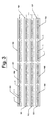
Figure 2 is a perspective representation of a number of series junctions of the tanks ofFigure 1 forming batteries, joined in parallel by a single general water inlet. -
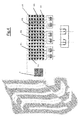
Figure 3 is a schematic representation of the junctions of the tanks ofFigure 1 in series and in parallel. -
Figure 4 is a schematic representation of the assembly of a renewable energy plant with water according to the distribution ofFigure 3 . - The invention comprises a certain number of isolated tanks (1) (
Fig.1 ) defined as cells, each containing individual blocks of sheets made of copper (2) or made of a metal of similar reducing nature and sheets made of zinc (3) or made of a metal of similar oxidizing nature, both submerged in water. These tanks (1) are connected together in series and in parallel in a particular way, increasing the voltage and current of the plant assembly. The water contained in said tanks (1) is constantly renewed by means of a particular hydraulic system. - If the facility is at the land surface there is a cistern (8) (
Fig.3 ), so that the water from the sea, river, or the like enters directly into the cistern (8) and from it passes to the renewable energy plant. - The aforementioned tanks (1) or isolated cells have a certain size depending on the number and size of the plates of copper (2) and zinc (3), or metals of the same nature, they contain. In order to produce electrical power, these plates (2 and 3) are submerged in water at all times by means of a defined hydraulic system that will be set forth throughout the specification.
- By introducing two metals of different purity such as copper (2) and zinc (3), and having an electrical conductor means as it is the case of water, an electrochemical process is created, that is, the chemical energy generated from the exchange of electrons between the two metallic elements, is transformed into electrical energy.
- In this way each of these tanks (1) will form a galvanic cell, and as a result an electrical current is generated from a spontaneous chemical reaction.
- These tanks (1) are connected in series forming batteries (100) (
Fig.2 ), that is, the connection settings of the terminals of the devices are sequentially joined or connected. Thus, the current passing through all the tanks (1) is the same but the voltage of the battery assembly (100) increases. - In turn, these batteries (100) are also joined together in series forming blocks (101), and these blocks (101) in turn are also joined in series forming a row, so that the voltage increases in each series junction.
- Simultaneously the aforementioned row is joined in parallel with other rows of the same characteristics as the one described, so that the voltage that all the rows joined in parallel have is the same, but the current of the set increases in each of these parallel junctions. As a result of all these associations, both in series and in parallel, the energy of the renewable energy plant starts from very small potentials and gradually increases until achieving a considerable energy output.
- In order for this power generation to persist in time it is necessary that the water, which is introduced into each of the tanks (1) or cells, is continuously recirculated. Additionally, the water introduced in each one of them has to remain isolated for a sufficient time in order to generate the aforementioned electrical energy.
- For this, there is a hydraulic system which causes water (which acts as an electrolyte within the tanks (1)) to gradually regenerate at predetermined continuous intervals. Therefore, since the electric power, produced by the so-called redox reaction or copper (2) and zinc (3) (
Fig.1 ) spontaneous oxidation-reduction, is removed as it is produced, there must be a continuous water renewal which must simultaneously remain isolated for an interval of time (depending on the size of the tank (1) and the number of plates (2 and 3)), for the electric power generation to be permanent and continuous. - The hydraulic system through which the water enters and exits the various tanks (1) from which the aforementioned energy is obtained is constituted by a main water inlet pipe (6), an evacuation main pipe (7), secondary pipes (61 and 71), auxiliary pipes (62 and 72), solenoid valves (611, 621, 711 and 721), a charging valve (4) and a discharge valve (5).
- Water from the main pipe (6) enters the tank (1) by a secondary pipe (61) which has on its inlet a solenoid valve (611), this solenoid valve (611) controlling the flow of fluid to an accumulator charging valve (4).
- When the charging valve (4) fills a specific volume of water in the tank (1), that is, when all the zinc (3) and copper (4) plates are completely submerged, the outlet of the charging valve (4) is closed, leaving the aforementioned tank (1) isolated for a time sufficient for the redox reaction between the plates (2 and 3) to occur. The energy obtained from this reaction is transferred to the external electric system or circuit through terminals (11), which each of the tanks (1) has.
- Once the water inside the tank (1) has been isolated for the estimated time, a discharge valve (5) acts through which all of the fluid is discharged towards a secondary outlet pipe (71) having a solenoid valve (711) before the connection to an evacuation main pipe (7).
- Both the charging valve (4) and the discharge valve (5) are synchronized such that the tank (1) is continuously containing water inside; in this way before the end of the water evacuation through the discharge valve (5), the charging valve (4) fills again the tank (1) achieving continuous recirculation where water is gradually regenerated at continuous and predetermined intervals, generating constant values of electric power.
- Inside the tank (1) there are different types of sensors, as is the case of failure warning sensors (12) or gauges of the valves (4 and 5) and a filling shut-off sensor (13).
- The failure warning sensors (12) detect irregularities of the water level inside the tank (1), so that when the water level is above the predetermined level, this failure sensor (12) sends a warning signal through monitoring indicating that the discharge valve (5) is not working properly; similarly when the water level inside the tank (1) is below the predetermined level, the failure sensor (12) sends a warning signal to the corresponding panel indicating that the charging valve is not working properly.
- On the other hand, the filling shut-off sensor (13) is activated or acts when the filling of the tank (1) is performed by an auxiliary pipe (62).
- Before the entry of water into the secondary pipe (61) which directs the fluid to the charging valve (4), there is an auxiliary filling pipe (62). This auxiliary filling pipe (62) has a solenoid valve (621) on its inlet. So that when water is channelled to the charging valve (4), this solenoid valve (621) is closed. But when the water is channelled or directed through the auxiliary filling pipe (62), the solenoid valve (621) is open and the solenoid valve (611) that is on the secondary pipe (61) is closed.
- The auxiliary filling pipe (62) is connected directly to the tank (1) and it fills it with water before commissioning after maintenance or in the first use thereof. The filling shut-off sensor (13) cited above is intended to shut-off the water inlet in this initial filling. So that, when the shut-off sensor (13) detects that the tank is filled to a certain height it sends a signal to the solenoid valve (621) which is in the filling auxiliary line (62) and the water inlet is closed.
- Also connected directly to the tank (1) there is an auxiliary drain pipe (72), which on its other end is connected to the evacuation main pipe (7). This auxiliary pipe (72) has a solenoid valve (721) which remains closed when the discharge valve (5) is operating, and it opens when the solenoid valve (711) of the secondary outlet pipe (71) is closed.
- This auxiliary drain pipe (72) is intended to empty the tank (1) for maintenance, such as cleaning the zinc (3) sheets after the process of spontaneous oxidation-reduction of copper (2) and zinc (3).
- Once properly described the nature of the invention, it is noted for the appropriate purposes, that the same is not limited to the exact details of this disclosure, but otherwise, the changes deemed appropriate will be implemented, provided that they are claimed below.
Claims (2)
- Hydraulic renewable energy plant characterized in that it comprises tanks (1), which contain sheets of copper (2) and sheets of zinc (3) in individual blocks, which are filled with water and renewed continuously through a hydraulic system wherein the water from a main pipe (6) enters into each of the tanks (1) through a secondary pipe (61) having a solenoid valve (611) which in turn is connected to a charging valve (4) through which the tank (1) is filled to a certain volume of water, the aforementioned copper (2) and zinc (3) plates being fully submerged and isolated when the filling valve (4) outlet is closed transmitting energy to an external electrical system or circuit via terminals (11), and once the water inside the tank (1) has been isolated for an estimated time, a discharge valve (5) acts through which all the fluid is evacuated to a secondary outlet pipe (71) which has a solenoid valve (711) before connecting to a main evacuation pipe (7), both the charging valve (4) and the discharge valve (5) being synchronized; moreover, inside the tank (1) there is a failure sensor (12) for the charging and discharge valves (4 and 5) and a filling shut-off sensor (13) which is activated when the filling of the tank (1) is via an auxiliary pipe (62) having a solenoid valve (621) on its inlet and, moreover, there is also a drain auxiliary pipe (72) connected directly to the tank (1) which connects to the main evacuation pipe (7) previously mentioned, and it has a solenoid valve (721).
- Hydraulic renewable energy plant wherein the tank (1) according to claim 1 is characterized in that it is connected in series with other tanks (1) forming batteries (100), these batteries (100) are joined together in series forming blocks (101), these blocks (101), in turn, are connected sequentially forming a row, which is joined in parallel to other rows equal to that described.
Priority Applications (1)
| Application Number | Priority Date | Filing Date | Title |
|---|---|---|---|
| EP13382441.7A EP2869375B1 (en) | 2013-10-31 | 2013-10-31 | Hydraulic renewable energy plant |
Applications Claiming Priority (1)
| Application Number | Priority Date | Filing Date | Title |
|---|---|---|---|
| EP13382441.7A EP2869375B1 (en) | 2013-10-31 | 2013-10-31 | Hydraulic renewable energy plant |
Publications (2)
| Publication Number | Publication Date |
|---|---|
| EP2869375A1 true EP2869375A1 (en) | 2015-05-06 |
| EP2869375B1 EP2869375B1 (en) | 2020-04-15 |
Family
ID=49552304
Family Applications (1)
| Application Number | Title | Priority Date | Filing Date |
|---|---|---|---|
| EP13382441.7A Active EP2869375B1 (en) | 2013-10-31 | 2013-10-31 | Hydraulic renewable energy plant |
Country Status (1)
| Country | Link |
|---|---|
| EP (1) | EP2869375B1 (en) |
Cited By (1)
| Publication number | Priority date | Publication date | Assignee | Title |
|---|---|---|---|---|
| CN108463920A (en) * | 2016-01-14 | 2018-08-28 | 藤仓橡胶工业株式会社 | Metal-air battery cells and metal-air batteries |
Citations (5)
| Publication number | Priority date | Publication date | Assignee | Title |
|---|---|---|---|---|
| DE2417571A1 (en) * | 1973-04-13 | 1974-11-07 | Electromedia | HYDRAULICALLY RECHARGEABLE, DEPOLARIZED METAL GAS BATTERY SYSTEM |
| WO2003041211A2 (en) * | 2001-09-26 | 2003-05-15 | Evionyx, Inc. | Rechargeable and refuelable metal air electrochemical cell |
| WO2004102691A2 (en) * | 2003-05-16 | 2004-11-25 | Franco Stocchiero | Method for forming lead-acid batteries and plant for implementing said method |
| RO127064A0 (en) * | 2010-12-20 | 2012-01-30 | Ionel Pardos | Direct current installation based on electrolytic cell modules with copper-zinc electrodes in a nacl + ho electrolyte |
| WO2013090680A2 (en) * | 2011-12-14 | 2013-06-20 | Eos Energy Storage, Llc | Electrically rechargeable, metal anode cell and battery systems and methods |
-
2013
- 2013-10-31 EP EP13382441.7A patent/EP2869375B1/en active Active
Patent Citations (5)
| Publication number | Priority date | Publication date | Assignee | Title |
|---|---|---|---|---|
| DE2417571A1 (en) * | 1973-04-13 | 1974-11-07 | Electromedia | HYDRAULICALLY RECHARGEABLE, DEPOLARIZED METAL GAS BATTERY SYSTEM |
| WO2003041211A2 (en) * | 2001-09-26 | 2003-05-15 | Evionyx, Inc. | Rechargeable and refuelable metal air electrochemical cell |
| WO2004102691A2 (en) * | 2003-05-16 | 2004-11-25 | Franco Stocchiero | Method for forming lead-acid batteries and plant for implementing said method |
| RO127064A0 (en) * | 2010-12-20 | 2012-01-30 | Ionel Pardos | Direct current installation based on electrolytic cell modules with copper-zinc electrodes in a nacl + ho electrolyte |
| WO2013090680A2 (en) * | 2011-12-14 | 2013-06-20 | Eos Energy Storage, Llc | Electrically rechargeable, metal anode cell and battery systems and methods |
Cited By (2)
| Publication number | Priority date | Publication date | Assignee | Title |
|---|---|---|---|---|
| CN108463920A (en) * | 2016-01-14 | 2018-08-28 | 藤仓橡胶工业株式会社 | Metal-air battery cells and metal-air batteries |
| CN108463920B (en) * | 2016-01-14 | 2021-11-30 | 藤仓橡胶工业株式会社 | Metal-air battery cell and metal-air battery |
Also Published As
| Publication number | Publication date |
|---|---|
| EP2869375B1 (en) | 2020-04-15 |
Similar Documents
| Publication | Publication Date | Title |
|---|---|---|
| Alili et al. | Techno-economic assessment of integrating hydrogen energy storage technology with hybrid photovoltaic/pumped storage hydropower energy system | |
| Serna et al. | Offshore hydrogen production from wave energy | |
| CN105308309B (en) | Electricity generation system based on potential energy | |
| US20140158529A1 (en) | Blue power generation system | |
| TWI659157B (en) | Electrolytic seawater hydrogen recovery and power generation system | |
| Blanco et al. | Study of a pilot photovoltaic-electrolyser-fuel cell power system for a geothermal heat pump heated greenhouse and evaluation of the electrolyser efficiency and operational mode | |
| CN102192077B (en) | System and method for storing wave and tidal energy as well as method and system for generating electricity | |
| Blanco et al. | Hydrogen and renewable energy sources integrated system for greenhouse heating | |
| DE102020005091A1 (en) | High pressure pumped storage power plant system | |
| US11018350B2 (en) | Ionic electric power station | |
| CN204497322U (en) | The fuel cell hydrogen-feeding system of anti-hydrogen leak | |
| EP2869375B1 (en) | Hydraulic renewable energy plant | |
| CN103710724A (en) | Wind power-solar energy hydrogen production apparatus | |
| Tebibel et al. | Impact of the battery depth of discharge on the performance of photovoltaic hydrogen production unit with energy management strategy | |
| CN103789783A (en) | Wind power-solar energy hydrogen production device | |
| Dudek et al. | Technical Assessment of Green Hydrogen Production in Anion Exchange Membrane Electrolyzers Integrated with Off-grid Renewable Energy Systems at Different Scales | |
| DE202021100850U1 (en) | Supply system for electricity and heat | |
| CN219363819U (en) | Renewable energy hydrogen production and storage system for small offshore platform | |
| Ghenai et al. | Comparison of energy storage options and detrmination of suitable technique for solar power systems | |
| Jamali Ghahderijani et al. | One-dimensional Electrolyzer modeling and system sizing for solar hydrogen production: an economic approach | |
| CN109338397A (en) | A solar photovoltaic hydrogen production equipment | |
| KR20240175881A (en) | System and Method for producing hydrogen based on composite energy | |
| Kleperis et al. | Self-sufficient PV-H2 alternative energy objects | |
| Boulmrharj et al. | Performance analysis of a grid-connected pv panels-electrolyzer-fuel cell system for cogeneration in energy efficient buildings | |
| CN203159723U (en) | Solar hydrogen production system |
Legal Events
| Date | Code | Title | Description |
|---|---|---|---|
| PUAI | Public reference made under article 153(3) epc to a published international application that has entered the european phase |
Free format text: ORIGINAL CODE: 0009012 |
|
| 17P | Request for examination filed |
Effective date: 20140508 |
|
| AK | Designated contracting states |
Kind code of ref document: A1 Designated state(s): AL AT BE BG CH CY CZ DE DK EE ES FI FR GB GR HR HU IE IS IT LI LT LU LV MC MK MT NL NO PL PT RO RS SE SI SK SM TR |
|
| AX | Request for extension of the european patent |
Extension state: BA ME |
|
| STAA | Information on the status of an ep patent application or granted ep patent |
Free format text: STATUS: EXAMINATION IS IN PROGRESS |
|
| 17Q | First examination report despatched |
Effective date: 20161121 |
|
| GRAP | Despatch of communication of intention to grant a patent |
Free format text: ORIGINAL CODE: EPIDOSNIGR1 |
|
| STAA | Information on the status of an ep patent application or granted ep patent |
Free format text: STATUS: GRANT OF PATENT IS INTENDED |
|
| INTG | Intention to grant announced |
Effective date: 20191025 |
|
| GRAS | Grant fee paid |
Free format text: ORIGINAL CODE: EPIDOSNIGR3 |
|
| GRAA | (expected) grant |
Free format text: ORIGINAL CODE: 0009210 |
|
| STAA | Information on the status of an ep patent application or granted ep patent |
Free format text: STATUS: THE PATENT HAS BEEN GRANTED |
|
| AK | Designated contracting states |
Kind code of ref document: B1 Designated state(s): AL AT BE BG CH CY CZ DE DK EE ES FI FR GB GR HR HU IE IS IT LI LT LU LV MC MK MT NL NO PL PT RO RS SE SI SK SM TR |
|
| REG | Reference to a national code |
Ref country code: CH Ref legal event code: EP Ref country code: GB Ref legal event code: FG4D |
|
| REG | Reference to a national code |
Ref country code: DE Ref legal event code: R096 Ref document number: 602013067895 Country of ref document: DE |
|
| REG | Reference to a national code |
Ref country code: IE Ref legal event code: FG4D |
|
| REG | Reference to a national code |
Ref country code: AT Ref legal event code: REF Ref document number: 1258355 Country of ref document: AT Kind code of ref document: T Effective date: 20200515 |
|
| REG | Reference to a national code |
Ref country code: SE Ref legal event code: TRGR |
|
| REG | Reference to a national code |
Ref country code: NL Ref legal event code: FP |
|
| REG | Reference to a national code |
Ref country code: LT Ref legal event code: MG4D |
|
| PG25 | Lapsed in a contracting state [announced via postgrant information from national office to epo] |
Ref country code: NO Free format text: LAPSE BECAUSE OF FAILURE TO SUBMIT A TRANSLATION OF THE DESCRIPTION OR TO PAY THE FEE WITHIN THE PRESCRIBED TIME-LIMIT Effective date: 20200715 Ref country code: GR Free format text: LAPSE BECAUSE OF FAILURE TO SUBMIT A TRANSLATION OF THE DESCRIPTION OR TO PAY THE FEE WITHIN THE PRESCRIBED TIME-LIMIT Effective date: 20200716 Ref country code: IS Free format text: LAPSE BECAUSE OF FAILURE TO SUBMIT A TRANSLATION OF THE DESCRIPTION OR TO PAY THE FEE WITHIN THE PRESCRIBED TIME-LIMIT Effective date: 20200815 Ref country code: PT Free format text: LAPSE BECAUSE OF FAILURE TO SUBMIT A TRANSLATION OF THE DESCRIPTION OR TO PAY THE FEE WITHIN THE PRESCRIBED TIME-LIMIT Effective date: 20200817 Ref country code: FI Free format text: LAPSE BECAUSE OF FAILURE TO SUBMIT A TRANSLATION OF THE DESCRIPTION OR TO PAY THE FEE WITHIN THE PRESCRIBED TIME-LIMIT Effective date: 20200415 Ref country code: LT Free format text: LAPSE BECAUSE OF FAILURE TO SUBMIT A TRANSLATION OF THE DESCRIPTION OR TO PAY THE FEE WITHIN THE PRESCRIBED TIME-LIMIT Effective date: 20200415 |
|
| REG | Reference to a national code |
Ref country code: AT Ref legal event code: MK05 Ref document number: 1258355 Country of ref document: AT Kind code of ref document: T Effective date: 20200415 |
|
| PG25 | Lapsed in a contracting state [announced via postgrant information from national office to epo] |
Ref country code: BG Free format text: LAPSE BECAUSE OF FAILURE TO SUBMIT A TRANSLATION OF THE DESCRIPTION OR TO PAY THE FEE WITHIN THE PRESCRIBED TIME-LIMIT Effective date: 20200715 Ref country code: LV Free format text: LAPSE BECAUSE OF FAILURE TO SUBMIT A TRANSLATION OF THE DESCRIPTION OR TO PAY THE FEE WITHIN THE PRESCRIBED TIME-LIMIT Effective date: 20200415 Ref country code: RS Free format text: LAPSE BECAUSE OF FAILURE TO SUBMIT A TRANSLATION OF THE DESCRIPTION OR TO PAY THE FEE WITHIN THE PRESCRIBED TIME-LIMIT Effective date: 20200415 Ref country code: HR Free format text: LAPSE BECAUSE OF FAILURE TO SUBMIT A TRANSLATION OF THE DESCRIPTION OR TO PAY THE FEE WITHIN THE PRESCRIBED TIME-LIMIT Effective date: 20200415 |
|
| PG25 | Lapsed in a contracting state [announced via postgrant information from national office to epo] |
Ref country code: AL Free format text: LAPSE BECAUSE OF FAILURE TO SUBMIT A TRANSLATION OF THE DESCRIPTION OR TO PAY THE FEE WITHIN THE PRESCRIBED TIME-LIMIT Effective date: 20200415 |
|
| REG | Reference to a national code |
Ref country code: DE Ref legal event code: R097 Ref document number: 602013067895 Country of ref document: DE |
|
| PG25 | Lapsed in a contracting state [announced via postgrant information from national office to epo] |
Ref country code: EE Free format text: LAPSE BECAUSE OF FAILURE TO SUBMIT A TRANSLATION OF THE DESCRIPTION OR TO PAY THE FEE WITHIN THE PRESCRIBED TIME-LIMIT Effective date: 20200415 Ref country code: SM Free format text: LAPSE BECAUSE OF FAILURE TO SUBMIT A TRANSLATION OF THE DESCRIPTION OR TO PAY THE FEE WITHIN THE PRESCRIBED TIME-LIMIT Effective date: 20200415 Ref country code: DK Free format text: LAPSE BECAUSE OF FAILURE TO SUBMIT A TRANSLATION OF THE DESCRIPTION OR TO PAY THE FEE WITHIN THE PRESCRIBED TIME-LIMIT Effective date: 20200415 Ref country code: ES Free format text: LAPSE BECAUSE OF FAILURE TO SUBMIT A TRANSLATION OF THE DESCRIPTION OR TO PAY THE FEE WITHIN THE PRESCRIBED TIME-LIMIT Effective date: 20200415 Ref country code: RO Free format text: LAPSE BECAUSE OF FAILURE TO SUBMIT A TRANSLATION OF THE DESCRIPTION OR TO PAY THE FEE WITHIN THE PRESCRIBED TIME-LIMIT Effective date: 20200415 Ref country code: IT Free format text: LAPSE BECAUSE OF FAILURE TO SUBMIT A TRANSLATION OF THE DESCRIPTION OR TO PAY THE FEE WITHIN THE PRESCRIBED TIME-LIMIT Effective date: 20200415 Ref country code: AT Free format text: LAPSE BECAUSE OF FAILURE TO SUBMIT A TRANSLATION OF THE DESCRIPTION OR TO PAY THE FEE WITHIN THE PRESCRIBED TIME-LIMIT Effective date: 20200415 Ref country code: CZ Free format text: LAPSE BECAUSE OF FAILURE TO SUBMIT A TRANSLATION OF THE DESCRIPTION OR TO PAY THE FEE WITHIN THE PRESCRIBED TIME-LIMIT Effective date: 20200415 |
|
| PLBE | No opposition filed within time limit |
Free format text: ORIGINAL CODE: 0009261 |
|
| STAA | Information on the status of an ep patent application or granted ep patent |
Free format text: STATUS: NO OPPOSITION FILED WITHIN TIME LIMIT |
|
| PG25 | Lapsed in a contracting state [announced via postgrant information from national office to epo] |
Ref country code: PL Free format text: LAPSE BECAUSE OF FAILURE TO SUBMIT A TRANSLATION OF THE DESCRIPTION OR TO PAY THE FEE WITHIN THE PRESCRIBED TIME-LIMIT Effective date: 20200415 Ref country code: SK Free format text: LAPSE BECAUSE OF FAILURE TO SUBMIT A TRANSLATION OF THE DESCRIPTION OR TO PAY THE FEE WITHIN THE PRESCRIBED TIME-LIMIT Effective date: 20200415 |
|
| 26N | No opposition filed |
Effective date: 20210118 |
|
| PG25 | Lapsed in a contracting state [announced via postgrant information from national office to epo] |
Ref country code: SI Free format text: LAPSE BECAUSE OF FAILURE TO SUBMIT A TRANSLATION OF THE DESCRIPTION OR TO PAY THE FEE WITHIN THE PRESCRIBED TIME-LIMIT Effective date: 20200415 |
|
| REG | Reference to a national code |
Ref country code: CH Ref legal event code: PL |
|
| PG25 | Lapsed in a contracting state [announced via postgrant information from national office to epo] |
Ref country code: LU Free format text: LAPSE BECAUSE OF NON-PAYMENT OF DUE FEES Effective date: 20201031 Ref country code: MC Free format text: LAPSE BECAUSE OF FAILURE TO SUBMIT A TRANSLATION OF THE DESCRIPTION OR TO PAY THE FEE WITHIN THE PRESCRIBED TIME-LIMIT Effective date: 20200415 |
|
| REG | Reference to a national code |
Ref country code: BE Ref legal event code: MM Effective date: 20201031 |
|
| PG25 | Lapsed in a contracting state [announced via postgrant information from national office to epo] |
Ref country code: BE Free format text: LAPSE BECAUSE OF NON-PAYMENT OF DUE FEES Effective date: 20201031 Ref country code: CH Free format text: LAPSE BECAUSE OF NON-PAYMENT OF DUE FEES Effective date: 20201031 Ref country code: LI Free format text: LAPSE BECAUSE OF NON-PAYMENT OF DUE FEES Effective date: 20201031 |
|
| PG25 | Lapsed in a contracting state [announced via postgrant information from national office to epo] |
Ref country code: IE Free format text: LAPSE BECAUSE OF NON-PAYMENT OF DUE FEES Effective date: 20201031 |
|
| PG25 | Lapsed in a contracting state [announced via postgrant information from national office to epo] |
Ref country code: TR Free format text: LAPSE BECAUSE OF FAILURE TO SUBMIT A TRANSLATION OF THE DESCRIPTION OR TO PAY THE FEE WITHIN THE PRESCRIBED TIME-LIMIT Effective date: 20200415 Ref country code: MT Free format text: LAPSE BECAUSE OF FAILURE TO SUBMIT A TRANSLATION OF THE DESCRIPTION OR TO PAY THE FEE WITHIN THE PRESCRIBED TIME-LIMIT Effective date: 20200415 Ref country code: CY Free format text: LAPSE BECAUSE OF FAILURE TO SUBMIT A TRANSLATION OF THE DESCRIPTION OR TO PAY THE FEE WITHIN THE PRESCRIBED TIME-LIMIT Effective date: 20200415 |
|
| PG25 | Lapsed in a contracting state [announced via postgrant information from national office to epo] |
Ref country code: MK Free format text: LAPSE BECAUSE OF FAILURE TO SUBMIT A TRANSLATION OF THE DESCRIPTION OR TO PAY THE FEE WITHIN THE PRESCRIBED TIME-LIMIT Effective date: 20200415 |
|
| PGFP | Annual fee paid to national office [announced via postgrant information from national office to epo] |
Ref country code: NL Payment date: 20250428 Year of fee payment: 12 |
|
| PGFP | Annual fee paid to national office [announced via postgrant information from national office to epo] |
Ref country code: GB Payment date: 20250428 Year of fee payment: 12 |
|
| PGFP | Annual fee paid to national office [announced via postgrant information from national office to epo] |
Ref country code: FR Payment date: 20250429 Year of fee payment: 12 |
|
| PGFP | Annual fee paid to national office [announced via postgrant information from national office to epo] |
Ref country code: SE Payment date: 20250428 Year of fee payment: 12 |
|
| REG | Reference to a national code |
Ref country code: NL Ref legal event code: MM Effective date: 20251101 |
|
| GBPC | Gb: european patent ceased through non-payment of renewal fee |
Effective date: 20251031 |
|
| PG25 | Lapsed in a contracting state [announced via postgrant information from national office to epo] |
Ref country code: GB Free format text: LAPSE BECAUSE OF NON-PAYMENT OF DUE FEES Effective date: 20251031 |
|
| PGFP | Annual fee paid to national office [announced via postgrant information from national office to epo] |
Ref country code: DE Payment date: 20260430 Year of fee payment: 13 |
|
| PG25 | Lapsed in a contracting state [announced via postgrant information from national office to epo] |
Ref country code: SE Free format text: LAPSE BECAUSE OF NON-PAYMENT OF DUE FEES Effective date: 20251101 |
|
| PG25 | Lapsed in a contracting state [announced via postgrant information from national office to epo] |
Ref country code: NL Free format text: LAPSE BECAUSE OF NON-PAYMENT OF DUE FEES Effective date: 20251101 |
|
| PG25 | Lapsed in a contracting state [announced via postgrant information from national office to epo] |
Ref country code: FR Free format text: LAPSE BECAUSE OF NON-PAYMENT OF DUE FEES Effective date: 20251031 |