EP2869365A1 - Positive electrode for secondary batteries, secondary battery, and method for producing positive electrode for secondary batteries - Google Patents
Positive electrode for secondary batteries, secondary battery, and method for producing positive electrode for secondary batteries Download PDFInfo
- Publication number
- EP2869365A1 EP2869365A1 EP13810339.5A EP13810339A EP2869365A1 EP 2869365 A1 EP2869365 A1 EP 2869365A1 EP 13810339 A EP13810339 A EP 13810339A EP 2869365 A1 EP2869365 A1 EP 2869365A1
- Authority
- EP
- European Patent Office
- Prior art keywords
- positive electrode
- active material
- secondary battery
- electrode active
- material layer
- Prior art date
- Legal status (The legal status is an assumption and is not a legal conclusion. Google has not performed a legal analysis and makes no representation as to the accuracy of the status listed.)
- Withdrawn
Links
- 238000004519 manufacturing process Methods 0.000 title claims abstract description 18
- 239000007774 positive electrode material Substances 0.000 claims abstract description 203
- XAGFODPZIPBFFR-UHFFFAOYSA-N aluminium Chemical compound [Al] XAGFODPZIPBFFR-UHFFFAOYSA-N 0.000 claims abstract description 170
- 229910052782 aluminium Inorganic materials 0.000 claims abstract description 168
- 238000010438 heat treatment Methods 0.000 claims abstract description 82
- 239000000463 material Substances 0.000 claims abstract description 74
- WHXSMMKQMYFTQS-UHFFFAOYSA-N Lithium Chemical compound [Li] WHXSMMKQMYFTQS-UHFFFAOYSA-N 0.000 claims abstract description 44
- 229910052744 lithium Inorganic materials 0.000 claims abstract description 44
- 229910044991 metal oxide Inorganic materials 0.000 claims abstract description 44
- 150000004706 metal oxides Chemical class 0.000 claims abstract description 44
- OKTJSMMVPCPJKN-UHFFFAOYSA-N Carbon Chemical compound [C] OKTJSMMVPCPJKN-UHFFFAOYSA-N 0.000 claims abstract description 43
- 229930195733 hydrocarbon Natural products 0.000 claims abstract description 23
- 229910052799 carbon Inorganic materials 0.000 claims abstract description 22
- 150000002430 hydrocarbons Chemical class 0.000 claims abstract description 21
- 239000000126 substance Substances 0.000 claims abstract description 18
- 239000004215 Carbon black (E152) Substances 0.000 claims abstract description 17
- 229910001416 lithium ion Inorganic materials 0.000 claims description 20
- HBBGRARXTFLTSG-UHFFFAOYSA-N Lithium ion Chemical group [Li+] HBBGRARXTFLTSG-UHFFFAOYSA-N 0.000 claims description 19
- 229910052493 LiFePO4 Inorganic materials 0.000 claims description 15
- 229920000642 polymer Polymers 0.000 claims description 6
- CAVCGVPGBKGDTG-UHFFFAOYSA-N alumanylidynemethyl(alumanylidynemethylalumanylidenemethylidene)alumane Chemical compound [Al]#C[Al]=C=[Al]C#[Al] CAVCGVPGBKGDTG-UHFFFAOYSA-N 0.000 claims description 3
- 230000000052 comparative effect Effects 0.000 description 84
- 239000011888 foil Substances 0.000 description 81
- 239000011230 binding agent Substances 0.000 description 54
- VNWKTOKETHGBQD-UHFFFAOYSA-N methane Chemical compound C VNWKTOKETHGBQD-UHFFFAOYSA-N 0.000 description 38
- 239000002245 particle Substances 0.000 description 37
- 239000002002 slurry Substances 0.000 description 34
- 239000002033 PVDF binder Substances 0.000 description 29
- 229920002981 polyvinylidene fluoride Polymers 0.000 description 29
- 238000000576 coating method Methods 0.000 description 28
- 239000011248 coating agent Substances 0.000 description 26
- 238000001035 drying Methods 0.000 description 26
- 239000002904 solvent Substances 0.000 description 25
- ZWEHNKRNPOVVGH-UHFFFAOYSA-N 2-Butanone Chemical compound CCC(C)=O ZWEHNKRNPOVVGH-UHFFFAOYSA-N 0.000 description 24
- KFZMGEQAYNKOFK-UHFFFAOYSA-N Isopropanol Chemical compound CC(C)O KFZMGEQAYNKOFK-UHFFFAOYSA-N 0.000 description 24
- YXFVVABEGXRONW-UHFFFAOYSA-N Toluene Chemical compound CC1=CC=CC=C1 YXFVVABEGXRONW-UHFFFAOYSA-N 0.000 description 24
- 230000010287 polarization Effects 0.000 description 24
- SECXISVLQFMRJM-UHFFFAOYSA-N N-Methylpyrrolidone Chemical compound CN1CCCC1=O SECXISVLQFMRJM-UHFFFAOYSA-N 0.000 description 20
- 239000012298 atmosphere Substances 0.000 description 18
- 239000007789 gas Substances 0.000 description 17
- 239000006230 acetylene black Substances 0.000 description 14
- 229920005989 resin Polymers 0.000 description 14
- 239000011347 resin Substances 0.000 description 14
- 238000003825 pressing Methods 0.000 description 12
- 238000007606 doctor blade method Methods 0.000 description 11
- 239000000203 mixture Substances 0.000 description 11
- 238000000197 pyrolysis Methods 0.000 description 11
- 238000012360 testing method Methods 0.000 description 11
- ATUOYWHBWRKTHZ-UHFFFAOYSA-N Propane Chemical compound CCC ATUOYWHBWRKTHZ-UHFFFAOYSA-N 0.000 description 8
- 230000015572 biosynthetic process Effects 0.000 description 8
- 230000015556 catabolic process Effects 0.000 description 8
- 238000006731 degradation reaction Methods 0.000 description 8
- 238000007599 discharging Methods 0.000 description 8
- GELKBWJHTRAYNV-UHFFFAOYSA-K lithium iron phosphate Chemical compound [Li+].[Fe+2].[O-]P([O-])([O-])=O GELKBWJHTRAYNV-UHFFFAOYSA-K 0.000 description 8
- 238000000034 method Methods 0.000 description 8
- 239000012046 mixed solvent Substances 0.000 description 8
- 230000008595 infiltration Effects 0.000 description 7
- 238000001764 infiltration Methods 0.000 description 7
- 229920002037 poly(vinyl butyral) polymer Polymers 0.000 description 7
- PXHVJJICTQNCMI-UHFFFAOYSA-N Nickel Chemical compound [Ni] PXHVJJICTQNCMI-UHFFFAOYSA-N 0.000 description 5
- 239000003792 electrolyte Substances 0.000 description 5
- 229910052751 metal Inorganic materials 0.000 description 5
- -1 olefin hydrocarbons Chemical class 0.000 description 5
- OTMSDBZUPAUEDD-UHFFFAOYSA-N Ethane Chemical compound CC OTMSDBZUPAUEDD-UHFFFAOYSA-N 0.000 description 4
- KMTRUDSVKNLOMY-UHFFFAOYSA-N Ethylene carbonate Chemical compound O=C1OCCO1 KMTRUDSVKNLOMY-UHFFFAOYSA-N 0.000 description 4
- NTIZESTWPVYFNL-UHFFFAOYSA-N Methyl isobutyl ketone Chemical compound CC(C)CC(C)=O NTIZESTWPVYFNL-UHFFFAOYSA-N 0.000 description 4
- UIHCLUNTQKBZGK-UHFFFAOYSA-N Methyl isobutyl ketone Natural products CCC(C)C(C)=O UIHCLUNTQKBZGK-UHFFFAOYSA-N 0.000 description 4
- 239000011572 manganese Substances 0.000 description 4
- 239000001294 propane Substances 0.000 description 4
- 229910000838 Al alloy Inorganic materials 0.000 description 3
- XEEYBQQBJWHFJM-UHFFFAOYSA-N Iron Chemical compound [Fe] XEEYBQQBJWHFJM-UHFFFAOYSA-N 0.000 description 3
- 230000008859 change Effects 0.000 description 3
- 229910052748 manganese Inorganic materials 0.000 description 3
- 239000002184 metal Substances 0.000 description 3
- 238000001000 micrograph Methods 0.000 description 3
- 238000002156 mixing Methods 0.000 description 3
- 229910052759 nickel Inorganic materials 0.000 description 3
- KAKZBPTYRLMSJV-UHFFFAOYSA-N Butadiene Chemical compound C=CC=C KAKZBPTYRLMSJV-UHFFFAOYSA-N 0.000 description 2
- 229910014422 LiNi1/3Mn1/3Co1/3O2 Inorganic materials 0.000 description 2
- 229910002097 Lithium manganese(III,IV) oxide Inorganic materials 0.000 description 2
- OFBQJSOFQDEBGM-UHFFFAOYSA-N Pentane Chemical compound CCCCC OFBQJSOFQDEBGM-UHFFFAOYSA-N 0.000 description 2
- ISWSIDIOOBJBQZ-UHFFFAOYSA-N Phenol Chemical compound OC1=CC=CC=C1 ISWSIDIOOBJBQZ-UHFFFAOYSA-N 0.000 description 2
- 239000004372 Polyvinyl alcohol Substances 0.000 description 2
- MODGUXHMLLXODK-UHFFFAOYSA-N [Br].CO Chemical compound [Br].CO MODGUXHMLLXODK-UHFFFAOYSA-N 0.000 description 2
- 230000009471 action Effects 0.000 description 2
- HSFWRNGVRCDJHI-UHFFFAOYSA-N alpha-acetylene Natural products C#C HSFWRNGVRCDJHI-UHFFFAOYSA-N 0.000 description 2
- QVGXLLKOCUKJST-UHFFFAOYSA-N atomic oxygen Chemical compound [O] QVGXLLKOCUKJST-UHFFFAOYSA-N 0.000 description 2
- 239000011651 chromium Substances 0.000 description 2
- 238000005097 cold rolling Methods 0.000 description 2
- 239000010949 copper Substances 0.000 description 2
- 230000006866 deterioration Effects 0.000 description 2
- QHGJSLXSVXVKHZ-UHFFFAOYSA-N dilithium;dioxido(dioxo)manganese Chemical compound [Li+].[Li+].[O-][Mn]([O-])(=O)=O QHGJSLXSVXVKHZ-UHFFFAOYSA-N 0.000 description 2
- IEJIGPNLZYLLBP-UHFFFAOYSA-N dimethyl carbonate Chemical compound COC(=O)OC IEJIGPNLZYLLBP-UHFFFAOYSA-N 0.000 description 2
- 238000011156 evaluation Methods 0.000 description 2
- 230000020169 heat generation Effects 0.000 description 2
- 239000011261 inert gas Substances 0.000 description 2
- 229910052742 iron Inorganic materials 0.000 description 2
- NNPPMTNAJDCUHE-UHFFFAOYSA-N isobutane Chemical compound CC(C)C NNPPMTNAJDCUHE-UHFFFAOYSA-N 0.000 description 2
- 239000007788 liquid Substances 0.000 description 2
- VGYDTVNNDKLMHX-UHFFFAOYSA-N lithium;manganese;nickel;oxocobalt Chemical compound [Li].[Mn].[Ni].[Co]=O VGYDTVNNDKLMHX-UHFFFAOYSA-N 0.000 description 2
- 239000011777 magnesium Substances 0.000 description 2
- 238000012423 maintenance Methods 0.000 description 2
- 239000011255 nonaqueous electrolyte Substances 0.000 description 2
- 230000003647 oxidation Effects 0.000 description 2
- 238000007254 oxidation reaction Methods 0.000 description 2
- 238000010525 oxidative degradation reaction Methods 0.000 description 2
- 229910052760 oxygen Inorganic materials 0.000 description 2
- 239000001301 oxygen Substances 0.000 description 2
- 239000012188 paraffin wax Substances 0.000 description 2
- 229920002451 polyvinyl alcohol Polymers 0.000 description 2
- 229910052710 silicon Inorganic materials 0.000 description 2
- 239000000758 substrate Substances 0.000 description 2
- 239000010936 titanium Substances 0.000 description 2
- 229910052723 transition metal Inorganic materials 0.000 description 2
- XLYOFNOQVPJJNP-UHFFFAOYSA-N water Substances O XLYOFNOQVPJJNP-UHFFFAOYSA-N 0.000 description 2
- 239000004925 Acrylic resin Substances 0.000 description 1
- 229920000178 Acrylic resin Polymers 0.000 description 1
- 229910016384 Al4C3 Inorganic materials 0.000 description 1
- ZOXJGFHDIHLPTG-UHFFFAOYSA-N Boron Chemical compound [B] ZOXJGFHDIHLPTG-UHFFFAOYSA-N 0.000 description 1
- 229920000049 Carbon (fiber) Polymers 0.000 description 1
- VYZAMTAEIAYCRO-UHFFFAOYSA-N Chromium Chemical compound [Cr] VYZAMTAEIAYCRO-UHFFFAOYSA-N 0.000 description 1
- RYGMFSIKBFXOCR-UHFFFAOYSA-N Copper Chemical compound [Cu] RYGMFSIKBFXOCR-UHFFFAOYSA-N 0.000 description 1
- 239000004593 Epoxy Substances 0.000 description 1
- 239000001856 Ethyl cellulose Substances 0.000 description 1
- ZZSNKZQZMQGXPY-UHFFFAOYSA-N Ethyl cellulose Chemical compound CCOCC1OC(OC)C(OCC)C(OCC)C1OC1C(O)C(O)C(OC)C(CO)O1 ZZSNKZQZMQGXPY-UHFFFAOYSA-N 0.000 description 1
- GYHNNYVSQQEPJS-UHFFFAOYSA-N Gallium Chemical compound [Ga] GYHNNYVSQQEPJS-UHFFFAOYSA-N 0.000 description 1
- 229910006554 Li1+xMn2-x-yMyO4 Inorganic materials 0.000 description 1
- 229910006601 Li1+xMn2−x−yMyO4 Inorganic materials 0.000 description 1
- 229910011116 LiM2O4 Inorganic materials 0.000 description 1
- 229910001305 LiMPO4 Inorganic materials 0.000 description 1
- 229910017286 LixM2O4 Inorganic materials 0.000 description 1
- 229910015530 LixMO2 Inorganic materials 0.000 description 1
- FYYHWMGAXLPEAU-UHFFFAOYSA-N Magnesium Chemical compound [Mg] FYYHWMGAXLPEAU-UHFFFAOYSA-N 0.000 description 1
- PWHULOQIROXLJO-UHFFFAOYSA-N Manganese Chemical compound [Mn] PWHULOQIROXLJO-UHFFFAOYSA-N 0.000 description 1
- XUIMIQQOPSSXEZ-UHFFFAOYSA-N Silicon Chemical compound [Si] XUIMIQQOPSSXEZ-UHFFFAOYSA-N 0.000 description 1
- RTAQQCXQSZGOHL-UHFFFAOYSA-N Titanium Chemical compound [Ti] RTAQQCXQSZGOHL-UHFFFAOYSA-N 0.000 description 1
- 239000011149 active material Substances 0.000 description 1
- 150000001298 alcohols Chemical class 0.000 description 1
- 229910045601 alloy Inorganic materials 0.000 description 1
- 239000000956 alloy Substances 0.000 description 1
- 238000000137 annealing Methods 0.000 description 1
- 239000003849 aromatic solvent Substances 0.000 description 1
- 125000003118 aryl group Chemical group 0.000 description 1
- 238000005422 blasting Methods 0.000 description 1
- 229910052796 boron Inorganic materials 0.000 description 1
- 230000005587 bubbling Effects 0.000 description 1
- 239000006229 carbon black Substances 0.000 description 1
- 150000001722 carbon compounds Chemical class 0.000 description 1
- 229910052804 chromium Inorganic materials 0.000 description 1
- 239000004020 conductor Substances 0.000 description 1
- 229910052802 copper Inorganic materials 0.000 description 1
- 238000012937 correction Methods 0.000 description 1
- 239000013078 crystal Substances 0.000 description 1
- 238000000354 decomposition reaction Methods 0.000 description 1
- 230000003247 decreasing effect Effects 0.000 description 1
- 238000003618 dip coating Methods 0.000 description 1
- 230000000694 effects Effects 0.000 description 1
- 238000000635 electron micrograph Methods 0.000 description 1
- 238000005530 etching Methods 0.000 description 1
- 229920001249 ethyl cellulose Polymers 0.000 description 1
- 235000019325 ethyl cellulose Nutrition 0.000 description 1
- 125000002534 ethynyl group Chemical group [H]C#C* 0.000 description 1
- 238000001125 extrusion Methods 0.000 description 1
- 239000004744 fabric Substances 0.000 description 1
- 229910052733 gallium Inorganic materials 0.000 description 1
- 239000011521 glass Substances 0.000 description 1
- 239000010439 graphite Substances 0.000 description 1
- 229910002804 graphite Inorganic materials 0.000 description 1
- 238000005098 hot rolling Methods 0.000 description 1
- 239000012535 impurity Substances 0.000 description 1
- 239000000976 ink Substances 0.000 description 1
- 239000001282 iso-butane Substances 0.000 description 1
- 150000002576 ketones Chemical class 0.000 description 1
- 229910052749 magnesium Inorganic materials 0.000 description 1
- 238000005259 measurement Methods 0.000 description 1
- 238000012986 modification Methods 0.000 description 1
- 230000004048 modification Effects 0.000 description 1
- IJDNQMDRQITEOD-UHFFFAOYSA-N n-butane Chemical compound CCCC IJDNQMDRQITEOD-UHFFFAOYSA-N 0.000 description 1
- JRZJOMJEPLMPRA-UHFFFAOYSA-N olefin Natural products CCCCCCCC=C JRZJOMJEPLMPRA-UHFFFAOYSA-N 0.000 description 1
- 230000001590 oxidative effect Effects 0.000 description 1
- 229910052698 phosphorus Inorganic materials 0.000 description 1
- 239000000843 powder Substances 0.000 description 1
- 230000009467 reduction Effects 0.000 description 1
- 238000007788 roughening Methods 0.000 description 1
- 239000010703 silicon Substances 0.000 description 1
- HBMJWWWQQXIZIP-UHFFFAOYSA-N silicon carbide Chemical compound [Si+]#[C-] HBMJWWWQQXIZIP-UHFFFAOYSA-N 0.000 description 1
- 229910010271 silicon carbide Inorganic materials 0.000 description 1
- 238000004528 spin coating Methods 0.000 description 1
- 229910052717 sulfur Inorganic materials 0.000 description 1
- 239000004094 surface-active agent Substances 0.000 description 1
- JBQYATWDVHIOAR-UHFFFAOYSA-N tellanylidenegermanium Chemical compound [Te]=[Ge] JBQYATWDVHIOAR-UHFFFAOYSA-N 0.000 description 1
- 229910052719 titanium Inorganic materials 0.000 description 1
- 238000001291 vacuum drying Methods 0.000 description 1
- 229910052720 vanadium Inorganic materials 0.000 description 1
- LEONUFNNVUYDNQ-UHFFFAOYSA-N vanadium atom Chemical compound [V] LEONUFNNVUYDNQ-UHFFFAOYSA-N 0.000 description 1
- 239000004034 viscosity adjusting agent Substances 0.000 description 1
- 238000005406 washing Methods 0.000 description 1
Images



Classifications
-
- H—ELECTRICITY
- H01—ELECTRIC ELEMENTS
- H01M—PROCESSES OR MEANS, e.g. BATTERIES, FOR THE DIRECT CONVERSION OF CHEMICAL ENERGY INTO ELECTRICAL ENERGY
- H01M4/00—Electrodes
- H01M4/02—Electrodes composed of, or comprising, active material
- H01M4/62—Selection of inactive substances as ingredients for active masses, e.g. binders, fillers
- H01M4/621—Binders
-
- H—ELECTRICITY
- H01—ELECTRIC ELEMENTS
- H01M—PROCESSES OR MEANS, e.g. BATTERIES, FOR THE DIRECT CONVERSION OF CHEMICAL ENERGY INTO ELECTRICAL ENERGY
- H01M4/00—Electrodes
- H01M4/02—Electrodes composed of, or comprising, active material
- H01M4/13—Electrodes for accumulators with non-aqueous electrolyte, e.g. for lithium-accumulators; Processes of manufacture thereof
- H01M4/136—Electrodes based on inorganic compounds other than oxides or hydroxides, e.g. sulfides, selenides, tellurides, halogenides or LiCoFy
-
- H—ELECTRICITY
- H01—ELECTRIC ELEMENTS
- H01M—PROCESSES OR MEANS, e.g. BATTERIES, FOR THE DIRECT CONVERSION OF CHEMICAL ENERGY INTO ELECTRICAL ENERGY
- H01M10/00—Secondary cells; Manufacture thereof
- H01M10/05—Accumulators with non-aqueous electrolyte
- H01M10/052—Li-accumulators
-
- H—ELECTRICITY
- H01—ELECTRIC ELEMENTS
- H01M—PROCESSES OR MEANS, e.g. BATTERIES, FOR THE DIRECT CONVERSION OF CHEMICAL ENERGY INTO ELECTRICAL ENERGY
- H01M10/00—Secondary cells; Manufacture thereof
- H01M10/05—Accumulators with non-aqueous electrolyte
- H01M10/052—Li-accumulators
- H01M10/0525—Rocking-chair batteries, i.e. batteries with lithium insertion or intercalation in both electrodes; Lithium-ion batteries
-
- H—ELECTRICITY
- H01—ELECTRIC ELEMENTS
- H01M—PROCESSES OR MEANS, e.g. BATTERIES, FOR THE DIRECT CONVERSION OF CHEMICAL ENERGY INTO ELECTRICAL ENERGY
- H01M4/00—Electrodes
- H01M4/02—Electrodes composed of, or comprising, active material
- H01M4/04—Processes of manufacture in general
- H01M4/0402—Methods of deposition of the material
- H01M4/0404—Methods of deposition of the material by coating on electrode collectors
-
- H—ELECTRICITY
- H01—ELECTRIC ELEMENTS
- H01M—PROCESSES OR MEANS, e.g. BATTERIES, FOR THE DIRECT CONVERSION OF CHEMICAL ENERGY INTO ELECTRICAL ENERGY
- H01M4/00—Electrodes
- H01M4/02—Electrodes composed of, or comprising, active material
- H01M4/04—Processes of manufacture in general
- H01M4/0471—Processes of manufacture in general involving thermal treatment, e.g. firing, sintering, backing particulate active material, thermal decomposition, pyrolysis
-
- H—ELECTRICITY
- H01—ELECTRIC ELEMENTS
- H01M—PROCESSES OR MEANS, e.g. BATTERIES, FOR THE DIRECT CONVERSION OF CHEMICAL ENERGY INTO ELECTRICAL ENERGY
- H01M4/00—Electrodes
- H01M4/02—Electrodes composed of, or comprising, active material
- H01M4/13—Electrodes for accumulators with non-aqueous electrolyte, e.g. for lithium-accumulators; Processes of manufacture thereof
- H01M4/139—Processes of manufacture
- H01M4/1391—Processes of manufacture of electrodes based on mixed oxides or hydroxides, or on mixtures of oxides or hydroxides, e.g. LiCoOx
-
- H—ELECTRICITY
- H01—ELECTRIC ELEMENTS
- H01M—PROCESSES OR MEANS, e.g. BATTERIES, FOR THE DIRECT CONVERSION OF CHEMICAL ENERGY INTO ELECTRICAL ENERGY
- H01M4/00—Electrodes
- H01M4/02—Electrodes composed of, or comprising, active material
- H01M4/13—Electrodes for accumulators with non-aqueous electrolyte, e.g. for lithium-accumulators; Processes of manufacture thereof
- H01M4/139—Processes of manufacture
- H01M4/1397—Processes of manufacture of electrodes based on inorganic compounds other than oxides or hydroxides, e.g. sulfides, selenides, tellurides, halogenides or LiCoFy
-
- H—ELECTRICITY
- H01—ELECTRIC ELEMENTS
- H01M—PROCESSES OR MEANS, e.g. BATTERIES, FOR THE DIRECT CONVERSION OF CHEMICAL ENERGY INTO ELECTRICAL ENERGY
- H01M4/00—Electrodes
- H01M4/02—Electrodes composed of, or comprising, active material
- H01M4/36—Selection of substances as active materials, active masses, active liquids
- H01M4/58—Selection of substances as active materials, active masses, active liquids of inorganic compounds other than oxides or hydroxides, e.g. sulfides, selenides, tellurides, halogenides or LiCoFy; of polyanionic structures, e.g. phosphates, silicates or borates
- H01M4/5825—Oxygenated metallic salts or polyanionic structures, e.g. borates, phosphates, silicates, olivines
-
- H—ELECTRICITY
- H01—ELECTRIC ELEMENTS
- H01M—PROCESSES OR MEANS, e.g. BATTERIES, FOR THE DIRECT CONVERSION OF CHEMICAL ENERGY INTO ELECTRICAL ENERGY
- H01M4/00—Electrodes
- H01M4/02—Electrodes composed of, or comprising, active material
- H01M4/64—Carriers or collectors
- H01M4/66—Selection of materials
- H01M4/661—Metal or alloys, e.g. alloy coatings
-
- H—ELECTRICITY
- H01—ELECTRIC ELEMENTS
- H01M—PROCESSES OR MEANS, e.g. BATTERIES, FOR THE DIRECT CONVERSION OF CHEMICAL ENERGY INTO ELECTRICAL ENERGY
- H01M4/00—Electrodes
- H01M4/02—Electrodes composed of, or comprising, active material
- H01M4/64—Carriers or collectors
- H01M4/66—Selection of materials
- H01M4/663—Selection of materials containing carbon or carbonaceous materials as conductive part, e.g. graphite, carbon fibres
-
- H—ELECTRICITY
- H01—ELECTRIC ELEMENTS
- H01M—PROCESSES OR MEANS, e.g. BATTERIES, FOR THE DIRECT CONVERSION OF CHEMICAL ENERGY INTO ELECTRICAL ENERGY
- H01M10/00—Secondary cells; Manufacture thereof
- H01M10/05—Accumulators with non-aqueous electrolyte
- H01M10/056—Accumulators with non-aqueous electrolyte characterised by the materials used as electrolytes, e.g. mixed inorganic/organic electrolytes
- H01M10/0564—Accumulators with non-aqueous electrolyte characterised by the materials used as electrolytes, e.g. mixed inorganic/organic electrolytes the electrolyte being constituted of organic materials only
- H01M10/0565—Polymeric materials, e.g. gel-type or solid-type
-
- H—ELECTRICITY
- H01—ELECTRIC ELEMENTS
- H01M—PROCESSES OR MEANS, e.g. BATTERIES, FOR THE DIRECT CONVERSION OF CHEMICAL ENERGY INTO ELECTRICAL ENERGY
- H01M4/00—Electrodes
- H01M4/02—Electrodes composed of, or comprising, active material
- H01M2004/026—Electrodes composed of, or comprising, active material characterised by the polarity
- H01M2004/028—Positive electrodes
-
- H—ELECTRICITY
- H01—ELECTRIC ELEMENTS
- H01M—PROCESSES OR MEANS, e.g. BATTERIES, FOR THE DIRECT CONVERSION OF CHEMICAL ENERGY INTO ELECTRICAL ENERGY
- H01M2220/00—Batteries for particular applications
- H01M2220/30—Batteries in portable systems, e.g. mobile phone, laptop
-
- H—ELECTRICITY
- H01—ELECTRIC ELEMENTS
- H01M—PROCESSES OR MEANS, e.g. BATTERIES, FOR THE DIRECT CONVERSION OF CHEMICAL ENERGY INTO ELECTRICAL ENERGY
- H01M4/00—Electrodes
- H01M4/02—Electrodes composed of, or comprising, active material
- H01M4/04—Processes of manufacture in general
- H01M4/0402—Methods of deposition of the material
- H01M4/0409—Methods of deposition of the material by a doctor blade method, slip-casting or roller coating
-
- Y—GENERAL TAGGING OF NEW TECHNOLOGICAL DEVELOPMENTS; GENERAL TAGGING OF CROSS-SECTIONAL TECHNOLOGIES SPANNING OVER SEVERAL SECTIONS OF THE IPC; TECHNICAL SUBJECTS COVERED BY FORMER USPC CROSS-REFERENCE ART COLLECTIONS [XRACs] AND DIGESTS
- Y02—TECHNOLOGIES OR APPLICATIONS FOR MITIGATION OR ADAPTATION AGAINST CLIMATE CHANGE
- Y02E—REDUCTION OF GREENHOUSE GAS [GHG] EMISSIONS, RELATED TO ENERGY GENERATION, TRANSMISSION OR DISTRIBUTION
- Y02E60/00—Enabling technologies; Technologies with a potential or indirect contribution to GHG emissions mitigation
- Y02E60/10—Energy storage using batteries
-
- Y—GENERAL TAGGING OF NEW TECHNOLOGICAL DEVELOPMENTS; GENERAL TAGGING OF CROSS-SECTIONAL TECHNOLOGIES SPANNING OVER SEVERAL SECTIONS OF THE IPC; TECHNICAL SUBJECTS COVERED BY FORMER USPC CROSS-REFERENCE ART COLLECTIONS [XRACs] AND DIGESTS
- Y02—TECHNOLOGIES OR APPLICATIONS FOR MITIGATION OR ADAPTATION AGAINST CLIMATE CHANGE
- Y02P—CLIMATE CHANGE MITIGATION TECHNOLOGIES IN THE PRODUCTION OR PROCESSING OF GOODS
- Y02P70/00—Climate change mitigation technologies in the production process for final industrial or consumer products
- Y02P70/50—Manufacturing or production processes characterised by the final manufactured product
Definitions
- the present invention generally relates to a secondary battery positive electrode used as a positive electrode constituting a secondary battery, a secondary battery comprising the same, and a method for producing the secondary battery positive electrode.
- the present invention specifically relates to a secondary battery positive electrode used as a positive electrode of a lithium ion battery, lithium ion polymer battery, etc., a secondary battery comprising the same, and a method for producing the secondary battery positive electrode.
- Batteries are used as a means for directly converting chemical energy to electrical energy. Batteries discharge electric charge, or repeatedly charge and discharge electric charge using electrochemical changes, and are therefore used as power sources of various electrical and electronic devices.
- lithium ion batteries lithium ion polymer batteries, etc.
- lithium ion polymer batteries are used as power sources of mobile phones, personal computers, cameras, etc.
- a positive electrode for lithium ion batteries is produced by applying a positive electrode active material slurry prepared by mixing a positive electrode active material (e.g., Li 1+x Mn 2-x-y M y O 4 ), carbon particles, a binder, and a solvent (e.g., N-methyl-2-pyrrolidone (NMP)) to an aluminum foil, which is used as a collector, then drying the slurry, and performing pressing to a predetermined thickness, as described, for example, in JP2003-68282A (hereinafter, PTL 1).
- NMP N-methyl-2-pyrrolidone
- PVDF polyvinylidene fluoride
- PTL 2 JP2000-507996A
- PVDF used as a binder has low heat resistance, and may be degraded at a temperature of about 75°C. Even when PVDF with high heat resistance is used, PVDF is swollen by absorbing the electrolyte at a temperature exceeding 60°C, sometimes leading to peeling of the positive electrode active material. Further, when a lithium ion battery comprising a positive electrode obtained by binding a positive electrode active material to the surface of aluminum foil using PVDF is rapidly charged and discharged, the temperature of the inside of the battery increases due to heat generated by the electrical resistance of the battery during rapid charging and discharging. This causes a problem in that the capacity of the battery during rapid charging and discharging is lower than that during slow charging and discharging. That is, a lithium ion battery comprising a positive electrode in which a positive electrode active material is bound to the surface of aluminum foil using PVDF as a binder has the problem of inferior rapid charge and discharge characteristics.
- the positive electrode is deteriorated, and the capacity is significantly reduced. Consequently, the capacity of the battery becomes lower than when the battery is repeatedly charged and discharged in a low-temperature environment. That is, since a positive electrode in which a positive electrode active material is bound using PVDF as a binder is deteriorated by heat, the lithium ion battery comprising the positive electrode has the problem of inferior heat resistance.
- an object of the present invention is to provide a secondary battery positive electrode that can improve the rapid charge and discharge characteristics of a secondary battery and increase the heat resistance of the secondary battery; a secondary battery comprising the same; and a method for producing the secondary battery positive electrode.
- the secondary battery positive electrode according to the present invention comprises an aluminum material; a positive active material layer comprising a lithium-containing metal oxide as a positive active material, and formed on the surface of the aluminum material; and an intervening layer comprising aluminum and carbon, and formed between the aluminum material and the positive active material layer.
- the lithium-containing metal oxide as a positive electrode active material is preferably LiFePO 4 .
- the intervening layer preferably includes a surface portion formed at least in a partial region of the surface of the aluminum material and comprising aluminum carbide.
- the secondary battery according to the present invention comprises a secondary battery positive electrode having the above features.
- the secondary battery of the present invention is preferably a lithium ion battery or a lithium ion polymer battery.
- the method for producing a secondary battery positive electrode according to the present invention comprises the steps of:
- the heating step is preferably performed at a temperature of 450°C or more and less than 660°C.
- a positive electrode active material layer is bound to the surface of an aluminum material by means of an intervening layer, and the intervening layer is not deteriorated by heat generated during rapid charging and discharging of a secondary battery; thus, the rapid charge and discharge characteristics of the secondary battery can be improved, and the heat resistance of the secondary battery can be increased because the intervening layer is not deteriorated even when the secondary battery is used in a high-temperature environment. Moreover, since the obtained secondary battery has low resistance, the rapid charge and discharge characteristics of the secondary battery can be improved.
- a positive electrode active material layer comprising a lithium-containing metal oxide as a positive electrode active material is formed on the surface of an aluminum material.
- An intervening layer comprising aluminum and carbon is formed between the aluminum material and the positive electrode active material layer.
- the intervening layer comprising aluminum and carbon formed between the aluminum material and the positive electrode active material layer has the action of increasing the adhesion between the surface of the aluminum material and the positive electrode active material layer formed on the surface of the aluminum material.
- the intervening layer is not deteriorated, by heat generated during rapid charging and discharging of the secondary battery, or when the secondary battery is used in a high-temperature environment; thus, the rapid charge and discharge characteristics of the secondary battery can be improved, and the heat resistance of the secondary battery can be increased.
- the secondary battery has lower electric resistance, and the rapid charge and discharge characteristics of the secondary battery can be improved.
- the aluminum material used as the substrate of the secondary battery positive electrode is not particularly limited.
- the aluminum material may be pure aluminum or an aluminum alloy.
- Such an aluminum material preferably has an aluminum purity of 98 mass% or more, as measured by the method described in "JIS H2111."
- the aluminum material used in the present invention comprises an aluminum alloy having a composition containing a required amount of at least one alloy element selected from lead (Pb), silicon (Si), iron (Fe), copper (Cu), manganese (Mn), magnesium (Mg), chromium (Cr), zinc (Zn), titanium (Ti), vanadium (V), gallium (Ga), nickel (Ni), and boron (B); or comprises aluminum with a limited content of an inevitable impurity element mentioned above.
- the thickness of the aluminum material is not particularly limited, the thickness of a foil is preferably 5 ⁇ m or more and 200 ⁇ m or less, and the thickness of a plate is preferably more than 200 ⁇ m and 3 mm or less.
- the aluminum material may be produced by a known method. For example, molten metal of aluminum or an aluminum alloy having the above specific composition is prepared, the molten metal is cast to obtain an ingot, and the ingot is appropriately homogenized. Then, the ingot is subjected to hot rolling and cold rolling, thereby obtaining an aluminum material. Further, intermediate annealing may be performed at a temperature of 150°C or more and 400°C or less in the course of cold rolling.
- a positive electrode active material layer comprising a lithium-containing metal oxide as a positive electrode active material is formed on the surface of the aluminum material.
- the lithium-containing metal oxide is not particularly limited, as long as it is generally used as a positive electrode active material constituting the positive electrode of a lithium ion battery.
- the lithium-containing metal oxide is preferably one that is hardly decomposed by heat, less likely to undergo characteristic changes by heat, stable against heat, and heat-resistant, in a heating step described later.
- the lithium-containing metal oxide is represented by, for example, the general formula Li x MO 2 , Li x M 2 O 4 , Li x MAO 4 , or the like.
- M is one or more transition metal elements, such as Co, Ni, Mn, Fe, etc.
- A is P, Si, S, V, or the like.
- the lithium-containing metal oxide used in the present invention may be one whose composition or crystal structure does not change in the heating step. Specific examples thereof include LiMPO 4 , LiM 2 O 4 , and the like; further, LiFePO 4 is more preferred.
- M is one or more transition metal elements, such as Co, Ni, Mn, Fe, etc.
- the form of the lithium-containing metal oxide is not particularly limited. It is preferable, in terms of adhesion, conductivity, and high capacity, that the lithium-containing metal oxide is contained in the positive electrode active material layer in a state in which the surface of the metal oxide is not coated with carbon.
- the lithium-containing metal oxide may be contained in the positive electrode active material layer in a state in which the surface of the metal oxide is coated with carbon.
- the particle size of the lithium-containing metal oxide is not particularly limited, but is 0.001 ⁇ m or more and 100 ⁇ m or less, and preferably 0.001 ⁇ m or more and 50 ⁇ m or less, in terms of improving electrical characteristics.
- the positive electrode active material layer may be formed on at least one side or both sides of the aluminum material.
- the thickness of the positive electrode active material layer on one side is not particularly limited, but is preferably 1 ⁇ m or more and 500 ⁇ m or less, more preferably 10 ⁇ m or more and 200 ⁇ m or less, and even more preferably 10 ⁇ m or more and 100 ⁇ m or less, because the adhesion between the lithium-containing metal oxide and the aluminum material can be ensured.
- the positive electrode active material layer may be formed on the entire surface of the aluminum material, or the aluminum material may have a portion in which the positive electrode active material layer is not formed, depending on the application to be finally applied (for example, when the aluminum material is designed to have a part in which the positive electrode active material layer is not formed, so as to connect a terminal to the edge of the aluminum material).
- the positive electrode active material layer constituting the secondary battery positive electrode of the present invention contains carbide that is assumed to be converted from the binder by heat in the later-described heating step.
- the carbide serves as a conductive material to thereby increase the conductivity of the positive electrode active material layer.
- the positive electrode active material layer may suitably contain other components, such as carbon-containing particles acting as other active materials, a surfactant, a viscosity-adjusting agent, metal powder, etc., as required.
- the type of carbon-containing particles is not particularly limited. Examples of carbon-containing particles include activated carbon fibers, activated carbon cloth, activated carbon felt, activated carbon powder, India ink, carbon black, and graphite. Another preferable example of carbon-containing particles is a carbon compound, such as silicon carbide.
- an intervening layer comprising aluminum and carbon is formed between the aluminum material and the positive electrode active material layer.
- the intervening layer is preferably formed at least in a partial region of the surface of the aluminum material, and comprises aluminum carbide such as Al 4 C 3 . Due to the presence of the intervening layer, the positive electrode active material layer is firmly attached to the aluminum material.
- a plurality of intervening layers may be formed on the surface of the aluminum material in the shape of islands apart from each other or adjacent to each other.
- the size of the intervening layer is not particularly limited.
- the secondary battery positive electrode of the present invention having the above features is used to constitute a secondary battery.
- Examples of the secondary battery using the secondary battery positive electrode of the present invention include lithium ion batteries, lithium ion polymer batteries, and the like.
- the secondary battery comprising the secondary battery positive electrode of the present invention maintains stable rapid charge and discharge characteristics, and has a longer life.
- the method for producing a secondary battery positive electrode according to the present invention comprises the step of forming a positive electrode active material layer, wherein a positive electrode active material layer comprising a lithium-containing metal oxide as a positive electrode active material is formed on the surface of an aluminum material.
- a heating step is performed to heat the aluminum material with the positive electrode active material layer formed thereon in a space containing a hydrocarbon-containing substance, thereby obtaining a secondary battery positive electrode in which the positive electrode active material layer is formed on the surface of the aluminum material via an intervening layer comprising aluminum and carbon.
- a lithium-containing metal oxide is attached to the surface of an aluminum material to form a positive electrode active material layer comprising the lithium-containing metal oxide as a positive electrode active material on the surface of the aluminum material.
- the method for attaching the lithium-containing metal oxide as a positive electrode active material to the surface of the aluminum material is not particularly limited.
- lithium-containing metal oxide particles or a mixture of lithium-containing metal oxide particles and a binder is dispersed in a solvent to form a slurry, and the slurry is applied to the surface of the aluminum material.
- the coating method in this case is not particularly limited. Examples of the coating method include spin coating, bar coating, flow coating, dip coating, etc. Other examples of the attaching method include an extrusion method, etc.
- the type of solvent to be used is not particularly limited.
- the solvent include aromatic solvents, such as toluene; ketones, such as methyl ethyl ketone; alcohols, such as isopropyl alcohol; water; and the like.
- aromatic solvents such as toluene
- ketones such as methyl ethyl ketone
- alcohols such as isopropyl alcohol
- water water
- the amount of the solvent in the slurry is also not particularly limited.
- the amount of the solvent is set in the range of 1 g to 200 g based on 30 g of lithium-containing metal oxide particles to be dispersed in the solvent.
- the type of binder to be used is not particularly limited.
- the binder include polyvinyl alcohol-based resins, polyvinyl butyral-based resins, epoxy-based resins, aromatic resins having a ring structure (e.g., phenol-based resins), acrylic resins, and the like. Polyvinyl butyral-based resins are particularly preferred.
- the amount of the binder in the slurry is also not particularly limited. For example, the amount of the binder is set in the range of 0.1 g to 100 g based on 30 g of lithium-containing metal oxide particles to be dispersed in the solvent.
- the step of forming a positive electrode active material layer may include a step of drying the positive electrode active material layer formed on the surface of the aluminum material.
- the drying step may be performed by heating.
- the heating temperature in the drying step is not particularly limited, but is, for example, preferably 10°C or more and 150°C or less, and more preferably 50°C or more and 150°C or less. In this case, it is preferable to uniformly dry the positive electrode active material layer.
- the drying time is preferably 30 seconds or more and 5 hours or less, although it varies depending on the types of the solvent and binder used to attach the positive electrode active material.
- the heating temperature in the drying step is below 10°C
- the binder is not bound, and the positive electrode active material layer may be peeled from the surface of the aluminum material.
- the solvent may not be sufficiently volatilized, and may remain. The solvent may be rapidly volatilized upon heating in the subsequent heating step, thereby causing generation of bubbles (bubbling) in the positive electrode active material layer.
- the heating temperature in the drying step exceeds 400°C, cracks may be formed by rapid heating on the surface of the positive electrode active material layer.
- the positive electrode active material layer may be formed on at least one side of the aluminum material.
- the density of the positive electrode active material layer is not particularly limited. However, when the density of the positive electrode active material layer exceeds a predetermined range, the electrical characteristics of the positive electrode active material layer may be deteriorated. It is therefore preferable to adjust the density of the positive electrode active material layer within a predetermined range by suitably performing a pressing step.
- the pressing step may be performed at any time after the positive electrode active material layer is formed on the surface of the aluminum material; however, it is preferable to perform the pressing step before the later-described heating step, in terms of further improving the adhesion between the aluminum material and the positive electrode active material layer.
- the specific density range cannot be generally specified because it varies depending on the type of lithium-containing metal oxide, the type of binder, and the proportion of lithium-containing metal oxide and binder.
- LiFePO 4 is used as the lithium-containing metal oxide, it is preferable that the density of the positive electrode active material layer is 1 g/cm 3 to 3 g/cm 3 .
- an oxidation heating step may be performed to heat the aluminum material with the positive electrode active material layer formed thereon in an oxidizing atmosphere, such as air. Since the excessive binder is subjected to oxidative degradation by the oxidation heating step, spaces are formed in the positive electrode active material layer, following the oxidative degradation of the binder. This consequently facilitates the formation of an intervening layer comprising aluminum and carbon, which is to be formed in the later-described heating step, in the interface between the positive electrode active material layer and the aluminum material, thereby increasing adhesion.
- the aluminum material with the positive electrode active material layer formed thereon is heated in a space containing a hydrocarbon-containing substance, thereby forming an intervening layer comprising aluminum and carbon between the aluminum material and the positive electrode active material layer.
- the type of the hydrocarbon-containing substance used in the heating step is not particularly limited.
- the type of hydrocarbon-containing substance include paraffin hydrocarbons, such as methane, ethane, propane, n-butane, isobutane, and pentane; olefin hydrocarbons, such as ethylene, propylene, butene, and butadiene; acetylene hydrocarbons, such as acetylene; or derivatives of these hydrocarbons.
- paraffin hydrocarbons such as methane, ethane, and propane, are preferred because they become gas in the heating step.
- An even more preferred hydrocarbon is one of methane, ethane, and propane. The most preferable hydrocarbon is methane.
- the hydrocarbon-containing substance may be used in the form of liquid, gas, or the like, in the production method of the present invention.
- the hydrocarbon-containing substance is placed in a space in which the aluminum material is present, and may be introduced into the space, in which the aluminum material is placed, by any method.
- the hydrocarbon-containing substance is gas (methane, ethane, propane, etc.)
- the hydrocarbon-containing substance may be introduced alone or together with inert gas into a closed space where the heating step is to be performed.
- the hydrocarbon-containing substance is liquid
- the hydrocarbon-containing substance may be introduced alone or together with inert gas into the closed space so that the substance is vaporized in the space.
- the pressure of the heating atmosphere is not particularly limited, and may be ordinary pressure, reduced pressure, or increased pressure. Further, the pressure may be adjusted at any time while maintaining the temperature at a specific heating temperature, increasing the temperature to the specific heating temperature, or decreasing the temperature from the specific heating temperature.
- the mass ratio of the hydrocarbon-containing substance to be introduced into the space where the heating step is to be performed is not particularly limited; however, it is generally preferably 0.1 parts by mass or more and 50 parts by mass or less, and particularly preferably 0.5 parts by mass or more and 30 parts by mass or less, calculated as carbon, based on 100 parts by mass of aluminum.
- the heating temperature may be suitably set depending on the composition, etc., of the aluminum material to be heated, but is generally preferably 450°C or more and less than 660°C, and more preferably 530°C or more and 640°C or less.
- the production method of the present invention does not exclude heating the aluminum material at a temperature of less than 450°C.
- the aluminum material may be heated at a temperature of at least more than 300°C.
- the heating time is generally 1 hour or more and 100 hours or less, although it depends on the heating temperature, etc.
- the heating temperature is 400°C or more, it is preferable that the oxygen concentration in the heating atmosphere is 1.0 volume% or less.
- the oxygen concentration in the heating atmosphere at a heating temperature of 400°C or more exceeds 1.0 volume%, the thermally oxidized film on the surface of the aluminum material may be expanded, and the surface resistance value of the aluminum material may increase.
- the surface of the aluminum material may be roughened before the heating step.
- the surface roughening method is not particularly limited, and any known technique, such as washing, etching, or blasting, can be used.
- a positive electrode active material layer can be attached to the surface of an aluminum material by a simple method in which a positive electrode active material comprising a lithium-containing metal oxide as a positive electrode active material is attached to the surface of the aluminum material to form the positive electrode active material layer, and the aluminum material is heated in a space containing a hydrocarbon-containing substance.
- the intervening layer which contributes to the binding of the positive electrode active material layer to the surface of the aluminum material, is not deteriorated, even by heat generated during rapid charging and discharging of the secondary battery, or even when the secondary battery is used in a high-temperature environment; thus, the heat resistance of the secondary battery can be increased.
- the secondary battery has lower electric resistance, and the rapid charge and discharge characteristics of the secondary battery can be improved.
- Lithium iron phosphate (LiFePO 4 ) particles (pyrolysis temperature in air: 400°C or more) as a lithium-containing metal oxide, i.e., a positive electrode active material, and a polyvinyl butyral-based resin as a binder were mixed at a mass ratio of 80:20.
- the slurry was applied to the surface of aluminum foil having a purity of 99.85% by a doctor blade method with a coating amount of 6.2 mg/cm 2 (on a dry mass basis), and dried in a drying oven at a temperature of 120°C for 3 minutes, thereby forming a positive electrode active material layer on one surface of the aluminum foil.
- the aluminum foil with the positive electrode active material layer formed on its surface was heated and dried in an air atmosphere.
- the drying promotes the degradation of a fixed amount of binder, which can thereby adjust the binder content of the positive electrode active material layer.
- a gap is formed between the aluminum foil and the positive electrode active material layer in a subsequent heating step, facilitating the infiltration of methane gas, and the formation of an intervening layer. Consequently, the adhesion between the aluminum foil and the positive electrode active material layer is improved after the heating step.
- the aluminum foil with the positive electrode active material layer formed on its surface was maintained in a methane gas atmosphere at a temperature of 630°C for 20 hours, thereby forming an intervening layer between the aluminum foil and the positive electrode active material layer. Thereafter, the aluminum foil with the positive electrode active material layer formed on its surface was punched into a disc having a diameter of 15.5 mm, and pressed so that the density of the positive electrode active material layer (calculated from the coating amount and thickness) was 1.7 g/cm 3 .
- Fig. 1 shows the obtained micrograph. Specifically, the micrograph of Fig. 1 shows the surface of the intervening layer exposed after the removal of the aluminum material, observed from the back side of the positive electrode (intervening layer) toward the positive electrode active material layer. The magnification of the micrograph in Fig. 1 is 10,000-fold.
- Fig. 1 clearly shows that many intervening layers are formed in the shape of separate islands at least in a partial region of the surface of the aluminum material in the secondary battery positive electrode of Example 1.
- the thickness of the positive electrode active material layer in the secondary battery positive electrode of the present invention obtained in Example 1 was 40 ⁇ m, which was determined by measuring the thickness of the secondary battery positive electrode using a micrometer, and subtracting the thickness of the aluminum foil therefrom.
- Lithium iron phosphate (LiFePO 4 ) particles (pyrolysis temperature in air: 400°C or more) as a lithium-containing metal oxide, i.e., a positive electrode active material, polyvinylidene fluoride (PVDF) as a binder, and acetylene black particles were mixed at a mass ratio of 86:7:7.
- N-methyl-2-pyrrolidone (NMP) as a solvent was suitably added thereto to prepare a slurry.
- the slurry was applied to the surface of aluminum foil having the same composition as that used in Example 1 by a doctor blade method with a coating amount (on a dry mass basis) of 6.2 mg/cm 2 , and dried in a drying oven at a temperature of 120°C for 3 minutes, thereby forming a positive electrode active material layer on one surface of the aluminum foil.
- the aluminum foil with the positive electrode active material layer formed on its surface was further heated and dried to completely evaporate the solvent.
- the aluminum foil with the positive electrode active material layer formed on its surface was punched into a disc having a diameter of 15.5 mm, and pressed so that the density of the positive electrode active material layer (calculated from the coating amount and thickness) was 1.7 g/cm 3 .
- the thickness of the positive electrode active material layer in the secondary battery positive electrode of Comparative Example 1 was 40 ⁇ m, which was determined in the same manner as in Example 1.
- Lithium foil produced by Honjo Metal Co., Ltd.
- a non-aqueous electrolyte produced by Kishida Chemical Co., Ltd. obtained by dissolving lithium hexafluorophosphate at a ratio of 1 mol/l in a solvent prepared by mixing ethylene carbonate (EC) and dimethyl carbonate (DMC) at a volume ratio of 1:1 was used as an electrolyte
- TF4050 made of paper; produced by Nippon Kodoshi Corporation
- HS flat cells produced by KeihinRika Industry Co., Ltd.
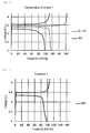
- FIG. 2 shows the results of the charge and discharge characteristics of the secondary battery obtained in the Example
- Fig. 3 shows the results of the charge and discharge characteristics of the secondary battery obtained in Comparative Example 1.
- Table 1 shows voltages (rate conditions) in the flat portions of the discharge curves of Figs. 2 and 3 at 0.1 C and 2 C, in which the voltages are flat.
- Table 1 Flat portion voltage [V] Ex. 1 Comp. Ex. 1 0.1 C 3.37 3.36 2 C 3.31 3.25
- Example 1 When the polarization A values at a rate of 2 C are compared between Example 1 and Comparative Example 1, the polarization A value of Example 1 is lower than that of Comparative Example 1, as shown in Table 2. It is thus found that the secondary battery of Example 1 has less resistance than the secondary battery of Comparative Example 1.
- Example 1 and Comparative Example 1 were each maintained at a temperature of 200°C for 12 hours to thereby produce secondary battery positive electrodes (after heating).
- secondary batteries were produced in the same manner as above.
- a charge/discharge test was performed using each of the secondary batteries of Example 1 and Comparative Example 1 at a rate of 2 C (rapid: high rate).
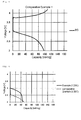
- Fig. 4 shows the results of the rapid (2 C) charge and discharge characteristics of the secondary battery of Example 1 produced using the secondary battery positive electrode (after heating), and Fig. 5 shows the results of the rapid (2 C) charge and discharge characteristics of the secondary battery obtained in Comparative Example 1.
- Table 3 shows voltages (after heating) in the flat portions of the discharge curves (2 C) of Figs. 4 and 5 , in which the voltages are flat.
- Table 3 also shows the voltages in the flat portions of the discharge curves (2 C) of Figs. 2 and 3 , in which the voltages are flat (the flat portion voltages at 2 C of the secondary batteries of Example 1 and Comparative Example 1 produced using the secondary battery positive electrodes (before heating) shown in Table 1).
- Example 1 and Comparative Example 1 are compared regarding the difference in polarization A between the secondary battery using the secondary battery positive electrode before heating and the secondary battery using the secondary battery positive electrode after heating
- Table 4 shows that the difference in polarization A is lower in Example 1 than in Comparative Example 1, which thus indicates that the secondary battery of Example 1 has heat resistance superior to that of the secondary battery of Comparative Example 1.
- the reason for this is considered to be as follows.
- the characteristics of the secondary battery of Comparative Example 1 were reduced, presumably because heating of the positive electrode caused the degradation or decomposition PVDF as a binder.
- the secondary battery of Example 1 showed little difference in the characteristics between before and after heating, presumably because the intervening layer had heat resistance.
- Lithium iron phosphate (LiFePO 4 ) particles (pyrolysis temperature in air: 400°C or more) as a lithium-containing metal oxide, i.e., a positive electrode active material, a polyvinyl butyral-based resin as a binder, and aluminum powder were mixed at a mass ratio of 88:5:7.
- a mixed solvent of toluene, methyl ethyl ketone, methyl isobutyl ketone, and isopropyl alcohol (volume ratio 7:1:1:1) as a solvent was suitably added thereto to prepare a slurry.
- the slurry was applied to the surface of aluminum foil having a purity of 99.85% by a doctor blade method with a coating amount (on a dry mass basis) of 10.5 mg/cm 2 , and dried in a drying oven at a temperature of 80°C for 3 minutes, thereby forming a positive electrode active material layer on one surface of the aluminum foil.
- the aluminum foil with the positive electrode active material layer formed on its surface was heated and dried in an air atmosphere.
- the drying promotes the degradation of a fixed amount of binder, which can thereby adjust the binder content of the positive electrode active material layer.
- a gap is formed between the aluminum foil and the positive electrode active material layer in a subsequent heating step, facilitating the infiltration of methane gas, and the formation of an intervening layer. Consequently, the adhesion between the aluminum foil and the positive electrode active material layer is improved after the heating step.
- the aluminum foil with the positive electrode active material layer formed on its surface was maintained in a methane gas atmosphere at a temperature of 630°C for 20 hours, thereby forming an intervening layer between the aluminum foil and the positive electrode active material layer. Thereafter, the aluminum foil with the positive electrode active material layer formed on its surface was punched into a disc having a diameter of 15.5 mm.
- the thickness of the positive electrode active material layer in the secondary battery positive electrode of the present invention obtained in Example 2 was 54 ⁇ m, which was determined in the same manner as in Example 1.
- the slurry was applied to the surface of aluminum foil having a purity of 99.85% by a doctor blade method with a coating amount (on a dry mass basis) of 5.4 mg/cm 2 , and dried in a drying oven at a temperature of 70°C for 5 minutes, thereby forming a positive electrode active material layer on one surface of the aluminum foil.
- the density of the positive electrode active material layer after coating was 1.54 mg/cm 3 .
- the aluminum foil with the positive electrode active material layer formed on its surface was heated and dried in an air atmosphere.
- the drying promotes the degradation of a fixed amount of binder, which can thereby adjust the binder content of the positive electrode active material layer.
- a gap is formed between the aluminum foil and the positive electrode active material layer in a subsequent heating step, facilitating the infiltration of methane gas, and the formation of an intervening layer. Consequently, the adhesion between the aluminum foil and the positive electrode active material layer is improved after the heating step.
- the aluminum foil with the positive electrode active material layer formed on its surface was maintained in a methane gas atmosphere at a temperature of 615°C for 12 hours, thereby forming an intervening layer between the aluminum foil and the positive electrode active material layer. Thereafter, the aluminum foil with the positive electrode active material layer formed on its surface was punched into a disc having a diameter of 15.5 mm.
- the thickness of the positive electrode active material layer in the secondary battery positive electrode of the present invention obtained in Example 3 was 35 ⁇ m, which was determined in the same manner as in Example 1.
- Lithium iron phosphate (LiFePO 4 ) particles (pyrolysis temperature in air: 400°C or more) as a lithium-containing metal oxide, i.e., a positive electrode active material, and a polyvinyl alcohol-based resin as a binder were mixed at a mass ratio of 80:20.
- a mixed solvent of water and isopropyl alcohol (volume ratio 1:1) as a solvent was suitably added thereto to prepare a slurry.
- the slurry was applied to the surface of aluminum foil having a purity of 99.85% by a doctor blade method with a coating amount (on a dry mass basis) of 5.1 mg/cm 2 , and dried in a drying oven at a temperature of 120°C for 5 minutes, thereby forming a positive electrode active material layer on one surface of the aluminum foil.
- the aluminum foil with the positive electrode active material layer formed on its surface was heated and dried in an air atmosphere.
- the drying promotes the degradation of a fixed amount of binder, which can thereby adjust the binder content of the positive electrode active material layer.
- a gap is formed between the aluminum foil and the positive electrode active material layer in a subsequent heating step, facilitating the infiltration of methane gas, and the formation of an intervening layer. Consequently, the adhesion between the aluminum foil and the positive electrode active material layer is improved after the heating step.
- the aluminum foil with the positive electrode active material layer formed on its surface was maintained in a methane gas atmosphere at a temperature of 630°C for 20 hours, thereby forming an intervening layer between the aluminum foil and the positive electrode active material layer. Thereafter, the aluminum foil with the positive electrode active material layer formed on its surface was punched into a disc having a diameter of 15.5 mm.
- the thickness of the positive electrode active material layer in the secondary battery positive electrode of the present invention obtained in Example 4 was 28 ⁇ m, which was determined in the same manner as in Example 1.
- Lithium iron phosphate (LiFePO 4 ) particles (pyrolysis temperature in air: 400°C or more) as a lithium-containing metal oxide, i.e., a positive electrode active material, a polyvinyl butyral-based resin as a binder, and aluminum powder were mixed at a mass ratio of 88:5:7.
- a mixed solvent of toluene, methyl ethyl ketone, methyl isobutyl ketone, and isopropyl alcohol (volume ratio 7:1:1:1) as a solvent was suitably added thereto to prepare a slurry.
- the slurry was applied to the surface of aluminum foil having a purity of 99.85% by a doctor blade method with a coating amount (on a dry mass basis) of 14.0 mg/cm 2 , and dried in a drying oven at a temperature of 80°C for 3 minutes, thereby forming a positive electrode active material layer on one surface of the aluminum foil.
- the aluminum foil with the positive electrode active material layer formed on its surface was heated and dried in an air atmosphere.
- the drying promotes the degradation of a fixed amount of binder, which can thereby adjust the binder content of the positive electrode active material layer.
- a gap is formed between the aluminum foil and the positive electrode active material layer in a subsequent heating step, facilitating the infiltration of methane gas, and the formation of an intervening layer. Consequently, the adhesion between the aluminum foil and the positive electrode active material layer is improved after the heating step.
- the aluminum foil with the positive electrode active material layer formed on its surface was maintained in a methane gas atmosphere at a temperature of 630°C for 20 hours, thereby forming an intervening layer between the aluminum foil and the positive electrode active material layer. Thereafter, the aluminum foil with the positive electrode active material layer formed on its surface was punched into a disc having a diameter of 15.5 mm.
- the thickness of the positive electrode active material layer in the secondary battery positive electrode of the present invention obtained in Example 5 was 69 ⁇ m, which was determined in the same manner as in Example 1.
- LiMn 2 O 4 particles pyrolysis temperature in air: 350°C or more
- a lithium-containing metal oxide i.e., a positive electrode active material
- a polyvinyl butyral-based resin as a binder
- the slurry was applied to the surface of aluminum foil having a purity of 99.85% by a doctor blade method with a coating amount (on a dry mass basis) of 7.0 mg/cm 2 , and dried in a drying oven at a temperature of 80°C for 3 minutes, thereby forming a positive electrode active material layer on one surface of the aluminum foil.
- the aluminum foil with the positive electrode active material layer formed on its surface was heated and dried in an air atmosphere.
- the drying promotes the degradation of a fixed amount of binder, which can thereby adjust the binder content of the positive electrode active material layer.
- a gap is formed between the aluminum foil and the positive electrode active material layer in a subsequent heating step, facilitating the infiltration of methane gas, and the formation of an intervening layer. Consequently, the adhesion between the aluminum foil and the positive electrode active material layer is improved after the heating step.
- the aluminum foil with the positive electrode active material layer formed on its surface was maintained in a methane gas atmosphere at a temperature of 615°C for 15 hours, thereby forming an intervening layer between the aluminum foil and the positive electrode active material layer. Thereafter, the aluminum foil with the positive electrode active material layer formed on its surface was punched into a disc having a diameter of 15.5 mm.
- the thickness of the positive electrode active material layer in the secondary battery positive electrode of the present invention obtained in Example 6 was 33 ⁇ m, which was determined in the same manner as in Example 1.
- Lithium nickel manganese cobalt oxide (LiNi 1/3 Mn 1/3 Co 1/3 O 2 ) particles (pyrolysis temperature in air: 300°C or more) as a lithium-containing metal oxide, i.e., a positive electrode active material, and a polyvinyl butyral-based resin as a binder were mixed at a mass ratio of 80:20.
- a mixed solvent of toluene, methyl ethyl ketone, methyl isobutyl ketone, and isopropyl alcohol (volume ratio 7:1:1:1) as a solvent was suitably added thereto to prepare a slurry.
- the slurry was applied to the surface of aluminum foil having a purity of 99.85% by a doctor blade method with a coating amount (on a dry mass basis) of 6.8 mg/cm 2 , and dried in a drying oven at a temperature of 50°C for 3 minutes, thereby forming a positive electrode active material layer on one surface of the aluminum foil.
- the aluminum foil with the positive electrode active material layer formed on its surface was heated and dried in an air atmosphere.
- the drying promotes the degradation of a fixed amount of binder, which can thereby adjust the binder content of the positive electrode active material layer.
- a gap is formed between the aluminum foil and the positive electrode active material layer in a subsequent heating step, facilitating the infiltration of methane gas, and the formation of an intervening layer. Consequently, the adhesion between the aluminum foil and the positive electrode active material layer is improved after the heating step.
- the aluminum foil with the positive electrode active material layer formed on its surface was maintained in a methane gas atmosphere at a temperature of 615°C for 15 hours, thereby forming an intervening layer between the aluminum foil and the positive electrode active material layer. Thereafter, the aluminum foil with the positive electrode active material layer formed on its surface was punched into a disc having a diameter of 15.5 mm.
- the thickness of the positive electrode active material layer in the secondary battery positive electrode of the present invention obtained in Example 7 was 31 ⁇ m, which was determined in the same manner as in Example 1.
- Lithium iron phosphate (LiFePO 4 ) particles (pyrolysis temperature in air: 400°C or more) as a lithium-containing metal oxide, i.e., a positive electrode active material, polyvinylidene fluoride (PVDF) as a binder, and acetylene black (AB) particles were mixed. N-methyl-2-pyrrolidone (NMP) as a solvent was suitably added thereto to prepare slurries.
- NMP N-methyl-2-pyrrolidone
- the proportions of iron phosphate lithium (LiFePO 4 ) particles, polyvinylidene fluoride (PVDF), and acetylene black (AB) particles are shown in Table 5 below as slurry proportions.
- the slurries were each applied to the surface of aluminum foil having the same composition as that used in Example 1 by a doctor blade method with the coating amount (on a dry mass basis) shown in Table 5, and dried in a drying oven at a temperature of 120°C for 10 minutes, thereby forming a positive electrode active material layer on one surface of the aluminum foil.
- each positive electrode active material layer (calculated from the coating amount and thickness) was in the range of 1.77 g/cm 3 to 2.07 g/cm 3 , and the aluminum foil with the positive electrode active material layer formed on its surface was punched into a disc having a diameter of 15.5 mm.
- Table 5 shows the specific density of each positive electrode active material.
- the thickness of the positive electrode active material layers in the secondary battery positive electrodes of Comparative Examples 2 to 5 was in the range of 25 ⁇ m to 54 ⁇ m, which was determined in the same manner as in Example 1.
- LiMn 2 O 4 Spinel-type lithium manganate (LiMn 2 O 4 ) particles (pyrolysis temperature in air: 350°C or more) as a lithium-containing metal oxide, i.e., a positive electrode active material, polyvinylidene fluoride (PVDF) as a binder, and acetylene black particles were mixed at a mass ratio of 90:5:5.
- NMP N-methyl-2-pyrrolidone
- the slurry was applied to the surface of aluminum foil having the same composition as that used in Example 1 by a doctor blade method with a coating amount (on a dry mass basis) of 6.2 mg/cm 2 , and dried in a drying oven at a temperature of 80°C for 20 minutes, thereby forming a positive electrode active material layer on one surface of the aluminum foil.
- the density of the positive electrode active material layer (calculated from the coating amount and thickness) was 2.14 g/cm 3 , and the aluminum foil with the positive electrode active material layer formed on its surface was punched into a disc having a diameter of 15.5 mm.
- the thickness of the positive electrode active material layer in the secondary battery positive electrode of Comparative Example 6 was 29 ⁇ m, which was determined in the same manner as in Example 1.
- Lithium nickel manganese cobalt oxide (LiNi 1/3 Mn 1/3 Co 1/3 O 2 ) particles (pyrolysis temperature in air: 300°C or more) as a lithium-containing metal oxide, i.e., a positive electrode active material, polyvinylidene fluoride (PVDF) as a binder, and acetylene black particles were mixed at a mass ratio of 90:5:5.
- NMP N-methyl-2-pyrrolidone
- the slurry was applied to the surface of aluminum foil having the same composition as that used in Example 1 by a doctor blade method with a coating amount (on a dry mass basis) of 5.5 mg/cm 2 , and dried in a drying oven at a temperature of 80°C for 20 minutes, thereby forming a positive electrode active material layer on one surface of the aluminum foil.
- the density of the positive electrode active material layer (calculated from the coating amount and thickness) was 2.20 g/cm 3 , and the aluminum foil with the positive electrode active material layer formed on its surface was punched into a disc having a diameter of 15.5 mm.
- the thickness of the positive electrode active material layer in the secondary battery positive electrode of the Comparative Example was 25 ⁇ m, which was determined in the same manner as in Example 1.
- Secondary batteries were produced using the secondary battery positive electrodes of Examples 2 to 5 and Comparative Example 2 to 5 in the following manner.
- the obtained positive electrode materials were heated and dried in a vacuum-drying furnace to completely evaporate the moisture.
- Lithium foil produced by Honjo Metal Co., Ltd.
- a non-aqueous electrolyte produced by Kishida Chemical Co., Ltd. obtained by dissolving lithium hexafluorophosphate at a ratio of 1 mol/l in a solvent prepared by mixing ethylene carbonate (EC) and dimethyl carbonate (DMC) at a volume ratio of 1:1 was used as an electrolyte
- a GA-100 glass filter produced by Toyo Roshi Kaisha, Ltd. was used as a separator.
- Fig. 6 shows the discharge curves at 20 C obtained in Example 2 and Comparative Example 2
- Fig. 7 shows the discharge curves at 2 C obtained in Example 3 and Comparative Example 3.
- Fig. 8 shows the results of the relationship between the discharge rate and average discharge voltage of the secondary batteries obtained in Example 2 and Comparative Example 2.
- Fig. 9 shows the results of the relationship between the discharge rate and average discharge voltage of the secondary batteries obtained in Example 3 and Comparative Example 3.
- Fig. 10 shows the results of the relationship between the discharge rate and average discharge voltage of the secondary batteries obtained in Example 4 and Comparative Example 4.
- Tables 6, 8, and 10 below show the average discharge voltage [V] calculated for each of the second batteries of Examples 2 to 4 and Comparative Examples 2 to 4.
- Tables 7, 9, and 11 below show the polarization B [V] calculated for each of the second batteries of Examples 2 to 4 and Comparative Example 2 to 4.
- Table 6 Average discharge voltage [V] Rate [C] Ex. 2 Comp. Ex. 2 0.5 3.35 3.30 20 2.78 2.33
- Table 7 Polarization B [V] Ex. 2 Comp. Ex. 2 0.5 C 0.08 0.13 20 C 0.65 1.10 Difference -0.57 -0.97
- Table 8 Average discharge voltage [V] Rate [C] Ex. 3 Comp. Ex. 3 0.5 3.28 3.22 2 3.21 3.01
- Table 9 Polarization B [V] Ex. 3 Comp. Ex. 3 0.5 C 0.15 0.21 2 C 0.22 0.42 Difference -0.07 -0.21
- Table 10 Average discharge voltage [V] Rate [C] Ex. 4 Comp. Ex. 4 0.5 3.30 3.26 5 3.06 2.81
- Table 11 Polarization B [V] Ex. 4 Comp. Ex. 4 0.5 C 0.13 0.17 5 C 0.37 0.62 Difference -0.24 -0.45
- Example 2 A comparison of Example 2 and Comparative Example 2 regarding the average discharge voltage values at a rate of 20 C revealed that the average discharge voltage value of Example 2 is higher than that of Comparative Example 2, as shown in Fig. 8 and Table 6, and the polarization of Example 2 is lower than that of Comparative Example 2, as shown in Table 7. This demonstrates that the secondary battery of Example 2 has less resistance than the secondary battery of Comparative Example 2.
- Example 3 A comparison of Example 3 and Comparative Example 3 regarding the average discharge voltage values at a rate of 2 C revealed that the average discharge voltage value of Example 3 is higher than that of Comparative Example 3, as shown in Fig. 9 and Table 8, and the polarization of Example 3 is lower than that of Comparative Example 3, as shown in Table 9. This demonstrates that the secondary battery of Example 3 has less resistance than the secondary battery of Comparative Example 3.
- Example 4 A comparison of Example 4 and Comparative Example 4 regarding the average discharge voltage values at a rate of 5 C revealed that the average discharge voltage value of Example 4 is higher than that of Comparative Example 4, as shown in Fig. 10 and Table 10, and the polarization of Example 4 is lower than that of Comparative Example 4, as shown in Table 11. This demonstrates that the secondary battery of Example 4 has less resistance than the secondary battery of Comparative Example 4.
- Example 6 and Comparative Example 6 and in Example 7 and Comparative Example 7 secondary batteries were produced, and the charge and discharge characteristics were observed. As a result, it was confirmed that the secondary batteries of the Examples had less resistance in both cases.
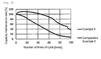
- Fig. 11 shows changes in discharge capacity relative to the number of times of cycle (capacity maintenance rate) in Example 5 and Comparative Example 5 when the initial discharge capacity was set to 100%
- Example 5 and Comparative Example 5 are compared regarding the changes in discharge capacity relative to the number of times of cycle, the reduction in discharge capacity is less in Example 5 than in Comparative Example 5, as shown in Fig. 11 .
- the reason for this is considered to be as follows.
- the characteristics of the secondary battery of Comparative Example 5 were reduced, presumably because heating of the secondary battery caused PVDF as a binder to absorb the electrolyte to be swollen, and the PVDF was deteriorated due to the repeated charge and discharge, leading to the peeling of the positive electrode active material layer.
- the decrease in the discharge capacity of the secondary battery of Example 5 was suppressed even when the battery was charged and discharged at a high temperature, presumably because a binder with a low heat resistance was not used, and the intervening layer had heat resistance.
- Example 6 and Comparative Example 6, and Example 7 and Comparative Example 7 secondary batteries were produced, and the heat resistance test B was performed to confirm the heat resistance of the secondary batteries. As a result, it was confirmed that the secondary batteries of Examples 6 and 7 had superior heat resistance in both cases.
- the secondary battery positive electrode of the present invention is used to constitute a secondary battery, particularly a lithium ion battery, lithium ion polymer battery, etc.
- the rapid charge and discharge characteristics of the secondary battery can be improved, and the heat resistance of the secondary battery can be increased.
Landscapes
- Chemical & Material Sciences (AREA)
- Engineering & Computer Science (AREA)
- Chemical Kinetics & Catalysis (AREA)
- Electrochemistry (AREA)
- General Chemical & Material Sciences (AREA)
- Manufacturing & Machinery (AREA)
- Materials Engineering (AREA)
- Inorganic Chemistry (AREA)
- Crystallography & Structural Chemistry (AREA)
- Battery Electrode And Active Subsutance (AREA)
- Cell Electrode Carriers And Collectors (AREA)
- Secondary Cells (AREA)
Abstract
Description
- The present invention generally relates to a secondary battery positive electrode used as a positive electrode constituting a secondary battery, a secondary battery comprising the same, and a method for producing the secondary battery positive electrode. The present invention specifically relates to a secondary battery positive electrode used as a positive electrode of a lithium ion battery, lithium ion polymer battery, etc., a secondary battery comprising the same, and a method for producing the secondary battery positive electrode.
- Batteries are used as a means for directly converting chemical energy to electrical energy. Batteries discharge electric charge, or repeatedly charge and discharge electric charge using electrochemical changes, and are therefore used as power sources of various electrical and electronic devices.
- Recently, as secondary batteries with high energy efficiency, lithium ion batteries, lithium ion polymer batteries, etc., are used as power sources of mobile phones, personal computers, cameras, etc.
- A positive electrode for lithium ion batteries is produced by applying a positive electrode active material slurry prepared by mixing a positive electrode active material (e.g., Li1+xMn2-x-yMyO4), carbon particles, a binder, and a solvent (e.g., N-methyl-2-pyrrolidone (NMP)) to an aluminum foil, which is used as a collector, then drying the slurry, and performing pressing to a predetermined thickness, as described, for example, in
JP2003-68282A PTL 1 andJP2000-507996A -
- PTL 1:
JP2003-68282A - PTL 2:
JP2000-507996A - However, PVDF used as a binder has low heat resistance, and may be degraded at a temperature of about 75°C. Even when PVDF with high heat resistance is used, PVDF is swollen by absorbing the electrolyte at a temperature exceeding 60°C, sometimes leading to peeling of the positive electrode active material. Further, when a lithium ion battery comprising a positive electrode obtained by binding a positive electrode active material to the surface of aluminum foil using PVDF is rapidly charged and discharged, the temperature of the inside of the battery increases due to heat generated by the electrical resistance of the battery during rapid charging and discharging. This causes a problem in that the capacity of the battery during rapid charging and discharging is lower than that during slow charging and discharging. That is, a lithium ion battery comprising a positive electrode in which a positive electrode active material is bound to the surface of aluminum foil using PVDF as a binder has the problem of inferior rapid charge and discharge characteristics.
- Recently, the use of secondary batteries in higher-temperature environments is required. However, when a lithium ion battery comprising the above positive electrode is rapidly charged and discharged in a high-temperature environment, there is a problem in that the capacity of the battery is lower than that in a low-temperature environment. The reason for this is as follows. Theoretically, since the conductivity of Li ions increases at a higher temperature, the capacity of the battery is supposed to increase when the battery is charged and discharged in a high-temperature environment. In practice, however, when charge and discharge are repeated in a high-temperature environment, PVDF is swollen by absorbing the electrolyte, leading to peeling of the positive electrode active material, as described above. As a result, the positive electrode is deteriorated, and the capacity is significantly reduced. Consequently, the capacity of the battery becomes lower than when the battery is repeatedly charged and discharged in a low-temperature environment. That is, since a positive electrode in which a positive electrode active material is bound using PVDF as a binder is deteriorated by heat, the lithium ion battery comprising the positive electrode has the problem of inferior heat resistance.
- Accordingly, an object of the present invention is to provide a secondary battery positive electrode that can improve the rapid charge and discharge characteristics of a secondary battery and increase the heat resistance of the secondary battery; a secondary battery comprising the same; and a method for producing the secondary battery positive electrode.
- The secondary battery positive electrode according to the present invention comprises an aluminum material; a positive active material layer comprising a lithium-containing metal oxide as a positive active material, and formed on the surface of the aluminum material; and an intervening layer comprising aluminum and carbon, and formed between the aluminum material and the positive active material layer.
- In the secondary battery positive electrode of the present invention, the lithium-containing metal oxide as a positive electrode active material is preferably LiFePO4.
- Moreover, in the secondary battery positive electrode of the present invention, the intervening layer preferably includes a surface portion formed at least in a partial region of the surface of the aluminum material and comprising aluminum carbide.
- The secondary battery according to the present invention comprises a secondary battery positive electrode having the above features.
- The secondary battery of the present invention is preferably a lithium ion battery or a lithium ion polymer battery.
- The method for producing a secondary battery positive electrode according to the present invention comprises the steps of:
- forming a positive active material layer comprising a lithium-containing metal oxide as a positive active material on the surface of an aluminum material; and
- heating the aluminum material with the positive active material layer formed thereon in a space containing a hydrocarbon-containing substance.
- In the method for producing a secondary battery positive electrode according to the present invention, the heating step is preferably performed at a temperature of 450°C or more and less than 660°C.
- According to the present invention, a positive electrode active material layer is bound to the surface of an aluminum material by means of an intervening layer, and the intervening layer is not deteriorated by heat generated during rapid charging and discharging of a secondary battery; thus, the rapid charge and discharge characteristics of the secondary battery can be improved, and the heat resistance of the secondary battery can be increased because the intervening layer is not deteriorated even when the secondary battery is used in a high-temperature environment. Moreover, since the obtained secondary battery has low resistance, the rapid charge and discharge characteristics of the secondary battery can be improved.
-
-
Fig. 1 shows an electron micrograph of the intervening layer in the secondary battery positive electrode produced in Example 1 of the present invention. The aluminum portion was dissolved in a bromine-methanol mixture, and the surface of the remaining intervening layer was directly observed by a scanning electron microscope (SEM). -
Fig. 2 shows the charge and discharge characteristics of a secondary battery comprising the secondary battery positive electrode produced in Example 1 of the present invention. -
Fig. 3 shows the charge and discharge characteristics of a secondary battery comprising the secondary battery positive electrode produced in Comparative Example 1 of the present invention. -
Fig. 4 shows the rapid (2 C) charge and discharge characteristics of a secondary battery comprising the heated secondary battery positive electrode produced in Example 1 of the present invention. -
Fig. 5 shows the rapid (2 C) charge and discharge characteristics of a secondary battery comprising the heated secondary battery positive electrode produced in Comparative Example 1 of the present invention. -
Fig. 6 shows the charge and discharge characteristics of secondary batteries respectively comprising the secondary battery positive electrodes produced in Example 2 and Comparative Example 2 of the present invention. -
Fig. 7 shows the charge and discharge characteristics of secondary batteries respectively comprising the secondary battery positive electrodes produced in Example 3 and Comparative Example 3 of the present invention. -
Fig. 8 shows the relationship between the discharge rate and average discharge voltage of secondary batteries respectively comprising the secondary battery positive electrodes produced in Example 2 and Comparative Example 2 of the present invention. -
Fig. 9 shows the relationship between the discharge rate and average discharge voltage of secondary batteries respectively comprising the secondary battery positive electrodes produced in Example 3 and Comparative Example 3 of the present invention. -
Fig. 10 shows the relationship between the discharge rate and average discharge voltage of secondary batteries respectively comprising the secondary battery positive electrodes produced in Example 4 and Comparative Example 4 of the present invention. -
Fig. 11 shows the changes in discharge capacity relative to the number of times of charge and discharge cycle (capacity maintenance rate) in a heat resistance test of secondary batteries respectively comprising the secondary battery positive electrodes produced in Example 5 and Comparative Example 5 of the present invention. - Embodiments of the present invention are described below.
- According to one embodiment of the present invention, in the cross-sectional structure of a secondary battery positive electrode, a positive electrode active material layer comprising a lithium-containing metal oxide as a positive electrode active material is formed on the surface of an aluminum material. An intervening layer comprising aluminum and carbon is formed between the aluminum material and the positive electrode active material layer.
- In the secondary battery positive electrode of the present invention, the intervening layer comprising aluminum and carbon formed between the aluminum material and the positive electrode active material layer has the action of increasing the adhesion between the surface of the aluminum material and the positive electrode active material layer formed on the surface of the aluminum material. As a result of this action, when the secondary battery positive electrode of the present invention is used in a secondary battery, such as a lithium ion battery, the intervening layer is not deteriorated, by heat generated during rapid charging and discharging of the secondary battery, or when the secondary battery is used in a high-temperature environment; thus, the rapid charge and discharge characteristics of the secondary battery can be improved, and the heat resistance of the secondary battery can be increased.
- Furthermore, the secondary battery has lower electric resistance, and the rapid charge and discharge characteristics of the secondary battery can be improved.
- According to one embodiment of the present invention, the aluminum material used as the substrate of the secondary battery positive electrode is not particularly limited. The aluminum material may be pure aluminum or an aluminum alloy. Such an aluminum material preferably has an aluminum purity of 98 mass% or more, as measured by the method described in "JIS H2111." The aluminum material used in the present invention comprises an aluminum alloy having a composition containing a required amount of at least one alloy element selected from lead (Pb), silicon (Si), iron (Fe), copper (Cu), manganese (Mn), magnesium (Mg), chromium (Cr), zinc (Zn), titanium (Ti), vanadium (V), gallium (Ga), nickel (Ni), and boron (B); or comprises aluminum with a limited content of an inevitable impurity element mentioned above. Although the thickness of the aluminum material is not particularly limited, the thickness of a foil is preferably 5 µm or more and 200 µm or less, and the thickness of a plate is preferably more than 200 µm and 3 mm or less.
- The aluminum material may be produced by a known method. For example, molten metal of aluminum or an aluminum alloy having the above specific composition is prepared, the molten metal is cast to obtain an ingot, and the ingot is appropriately homogenized. Then, the ingot is subjected to hot rolling and cold rolling, thereby obtaining an aluminum material. Further, intermediate annealing may be performed at a temperature of 150°C or more and 400°C or less in the course of cold rolling.
- In the secondary battery positive electrode of the present invention, a positive electrode active material layer comprising a lithium-containing metal oxide as a positive electrode active material is formed on the surface of the aluminum material.
- The lithium-containing metal oxide is not particularly limited, as long as it is generally used as a positive electrode active material constituting the positive electrode of a lithium ion battery. The lithium-containing metal oxide is preferably one that is hardly decomposed by heat, less likely to undergo characteristic changes by heat, stable against heat, and heat-resistant, in a heating step described later.
- The lithium-containing metal oxide is represented by, for example, the general formula LixMO2, LixM2O4, LixMAO4, or the like. Here, M is one or more transition metal elements, such as Co, Ni, Mn, Fe, etc. A is P, Si, S, V, or the like. The lithium-containing metal oxide used in the present invention may be one whose composition or crystal structure does not change in the heating step. Specific examples thereof include LiMPO4, LiM2O4, and the like; further, LiFePO4 is more preferred. Here, M is one or more transition metal elements, such as Co, Ni, Mn, Fe, etc.
- Moreover, the form of the lithium-containing metal oxide is not particularly limited. It is preferable, in terms of adhesion, conductivity, and high capacity, that the lithium-containing metal oxide is contained in the positive electrode active material layer in a state in which the surface of the metal oxide is not coated with carbon. The lithium-containing metal oxide may be contained in the positive electrode active material layer in a state in which the surface of the metal oxide is coated with carbon. Further, the particle size of the lithium-containing metal oxide is not particularly limited, but is 0.001 µm or more and 100 µm or less, and preferably 0.001 µm or more and 50 µm or less, in terms of improving electrical characteristics.
- The positive electrode active material layer may be formed on at least one side or both sides of the aluminum material. The thickness of the positive electrode active material layer on one side is not particularly limited, but is preferably 1 µm or more and 500 µm or less, more preferably 10 µm or more and 200 µm or less, and even more preferably 10 µm or more and 100 µm or less, because the adhesion between the lithium-containing metal oxide and the aluminum material can be ensured. Furthermore, the positive electrode active material layer may be formed on the entire surface of the aluminum material, or the aluminum material may have a portion in which the positive electrode active material layer is not formed, depending on the application to be finally applied (for example, when the aluminum material is designed to have a part in which the positive electrode active material layer is not formed, so as to connect a terminal to the edge of the aluminum material).
- In a later-described step of forming a positive electrode active material layer, when a positive electrode active material-containing slurry contains a binder, the positive electrode active material layer constituting the secondary battery positive electrode of the present invention contains carbide that is assumed to be converted from the binder by heat in the later-described heating step. In this case, the carbide serves as a conductive material to thereby increase the conductivity of the positive electrode active material layer.
- Further, the positive electrode active material layer may suitably contain other components, such as carbon-containing particles acting as other active materials, a surfactant, a viscosity-adjusting agent, metal powder, etc., as required. The type of carbon-containing particles is not particularly limited. Examples of carbon-containing particles include activated carbon fibers, activated carbon cloth, activated carbon felt, activated carbon powder, India ink, carbon black, and graphite. Another preferable example of carbon-containing particles is a carbon compound, such as silicon carbide.
- In the secondary battery positive electrode of the present invention, an intervening layer comprising aluminum and carbon is formed between the aluminum material and the positive electrode active material layer.
- The intervening layer is preferably formed at least in a partial region of the surface of the aluminum material, and comprises aluminum carbide such as Al4C3. Due to the presence of the intervening layer, the positive electrode active material layer is firmly attached to the aluminum material.
- In addition, a plurality of intervening layers may be formed on the surface of the aluminum material in the shape of islands apart from each other or adjacent to each other. The size of the intervening layer is not particularly limited.
- The secondary battery positive electrode of the present invention having the above features is used to constitute a secondary battery. Examples of the secondary battery using the secondary battery positive electrode of the present invention include lithium ion batteries, lithium ion polymer batteries, and the like. The secondary battery comprising the secondary battery positive electrode of the present invention maintains stable rapid charge and discharge characteristics, and has a longer life.
- The method for producing a secondary battery positive electrode according to the present invention comprises the step of forming a positive electrode active material layer, wherein a positive electrode active material layer comprising a lithium-containing metal oxide as a positive electrode active material is formed on the surface of an aluminum material. Following the step of forming a positive electrode active material layer, a heating step is performed to heat the aluminum material with the positive electrode active material layer formed thereon in a space containing a hydrocarbon-containing substance, thereby obtaining a secondary battery positive electrode in which the positive electrode active material layer is formed on the surface of the aluminum material via an intervening layer comprising aluminum and carbon.
- In one embodiment of the method for producing a secondary battery positive electrode according to the present invention, first, a lithium-containing metal oxide is attached to the surface of an aluminum material to form a positive electrode active material layer comprising the lithium-containing metal oxide as a positive electrode active material on the surface of the aluminum material.
- In the step of forming a positive electrode active material layer, the method for attaching the lithium-containing metal oxide as a positive electrode active material to the surface of the aluminum material is not particularly limited. For example, lithium-containing metal oxide particles or a mixture of lithium-containing metal oxide particles and a binder is dispersed in a solvent to form a slurry, and the slurry is applied to the surface of the aluminum material. The coating method in this case is not particularly limited. Examples of the coating method include spin coating, bar coating, flow coating, dip coating, etc. Other examples of the attaching method include an extrusion method, etc.
- When the slurry is applied to the surface of the aluminum material, as described above, the type of solvent to be used is not particularly limited. Examples of the solvent include aromatic solvents, such as toluene; ketones, such as methyl ethyl ketone; alcohols, such as isopropyl alcohol; water; and the like. For example, a mixed solvent of toluene, methyl ethyl ketone, and isopropyl alcohol at a volume ratio of 6:3:1 can be used. The amount of the solvent in the slurry is also not particularly limited. For example, the amount of the solvent is set in the range of 1 g to 200 g based on 30 g of lithium-containing metal oxide particles to be dispersed in the solvent.
- Further, when the slurry contains a binder, the type of binder to be used is not particularly limited. Examples of the binder include polyvinyl alcohol-based resins, polyvinyl butyral-based resins, epoxy-based resins, aromatic resins having a ring structure (e.g., phenol-based resins), acrylic resins, and the like. Polyvinyl butyral-based resins are particularly preferred. The amount of the binder in the slurry is also not particularly limited. For example, the amount of the binder is set in the range of 0.1 g to 100 g based on 30 g of lithium-containing metal oxide particles to be dispersed in the solvent.
- The step of forming a positive electrode active material layer may include a step of drying the positive electrode active material layer formed on the surface of the aluminum material. The drying step may be performed by heating. The heating temperature in the drying step is not particularly limited, but is, for example, preferably 10°C or more and 150°C or less, and more preferably 50°C or more and 150°C or less. In this case, it is preferable to uniformly dry the positive electrode active material layer. Moreover, the drying time is preferably 30 seconds or more and 5 hours or less, although it varies depending on the types of the solvent and binder used to attach the positive electrode active material.
- When the heating temperature in the drying step is below 10°C, the binder is not bound, and the positive electrode active material layer may be peeled from the surface of the aluminum material. Moreover, when the positive electrode active material is attached by applying a slurry, the solvent may not be sufficiently volatilized, and may remain. The solvent may be rapidly volatilized upon heating in the subsequent heating step, thereby causing generation of bubbles (bubbling) in the positive electrode active material layer. In contrast, when the heating temperature in the drying step exceeds 400°C, cracks may be formed by rapid heating on the surface of the positive electrode active material layer.
- The positive electrode active material layer may be formed on at least one side of the aluminum material. Moreover, the density of the positive electrode active material layer is not particularly limited. However, when the density of the positive electrode active material layer exceeds a predetermined range, the electrical characteristics of the positive electrode active material layer may be deteriorated. It is therefore preferable to adjust the density of the positive electrode active material layer within a predetermined range by suitably performing a pressing step. The pressing step may be performed at any time after the positive electrode active material layer is formed on the surface of the aluminum material; however, it is preferable to perform the pressing step before the later-described heating step, in terms of further improving the adhesion between the aluminum material and the positive electrode active material layer. The specific density range cannot be generally specified because it varies depending on the type of lithium-containing metal oxide, the type of binder, and the proportion of lithium-containing metal oxide and binder. When LiFePO4 is used as the lithium-containing metal oxide, it is preferable that the density of the positive electrode active material layer is 1 g/cm3 to 3 g/cm3.
- Further, after the drying step, an oxidation heating step may be performed to heat the aluminum material with the positive electrode active material layer formed thereon in an oxidizing atmosphere, such as air. Since the excessive binder is subjected to oxidative degradation by the oxidation heating step, spaces are formed in the positive electrode active material layer, following the oxidative degradation of the binder. This consequently facilitates the formation of an intervening layer comprising aluminum and carbon, which is to be formed in the later-described heating step, in the interface between the positive electrode active material layer and the aluminum material, thereby increasing adhesion.
- After the step of forming a positive electrode active material layer, the aluminum material with the positive electrode active material layer formed thereon is heated in a space containing a hydrocarbon-containing substance, thereby forming an intervening layer comprising aluminum and carbon between the aluminum material and the positive electrode active material layer.
- In one embodiment of the method for producing a secondary battery positive electrode according to the present invention, the type of the hydrocarbon-containing substance used in the heating step is not particularly limited. Examples of the type of hydrocarbon-containing substance include paraffin hydrocarbons, such as methane, ethane, propane, n-butane, isobutane, and pentane; olefin hydrocarbons, such as ethylene, propylene, butene, and butadiene; acetylene hydrocarbons, such as acetylene; or derivatives of these hydrocarbons. Among these hydrocarbons, paraffin hydrocarbons, such as methane, ethane, and propane, are preferred because they become gas in the heating step. An even more preferred hydrocarbon is one of methane, ethane, and propane. The most preferable hydrocarbon is methane.
- The hydrocarbon-containing substance may be used in the form of liquid, gas, or the like, in the production method of the present invention. The hydrocarbon-containing substance is placed in a space in which the aluminum material is present, and may be introduced into the space, in which the aluminum material is placed, by any method. For example, when the hydrocarbon-containing substance is gas (methane, ethane, propane, etc.), the hydrocarbon-containing substance may be introduced alone or together with inert gas into a closed space where the heating step is to be performed. Alternatively, when the hydrocarbon-containing substance is liquid, the hydrocarbon-containing substance may be introduced alone or together with inert gas into the closed space so that the substance is vaporized in the space.
- In the heating step, the pressure of the heating atmosphere is not particularly limited, and may be ordinary pressure, reduced pressure, or increased pressure. Further, the pressure may be adjusted at any time while maintaining the temperature at a specific heating temperature, increasing the temperature to the specific heating temperature, or decreasing the temperature from the specific heating temperature.
- The mass ratio of the hydrocarbon-containing substance to be introduced into the space where the heating step is to be performed is not particularly limited; however, it is generally preferably 0.1 parts by mass or more and 50 parts by mass or less, and particularly preferably 0.5 parts by mass or more and 30 parts by mass or less, calculated as carbon, based on 100 parts by mass of aluminum.
- In the heating step, the heating temperature may be suitably set depending on the composition, etc., of the aluminum material to be heated, but is generally preferably 450°C or more and less than 660°C, and more preferably 530°C or more and 640°C or less. However, the production method of the present invention does not exclude heating the aluminum material at a temperature of less than 450°C. The aluminum material may be heated at a temperature of at least more than 300°C.
- The heating time is generally 1 hour or more and 100 hours or less, although it depends on the heating temperature, etc. When the heating temperature is 400°C or more, it is preferable that the oxygen concentration in the heating atmosphere is 1.0 volume% or less. When the oxygen concentration in the heating atmosphere at a heating temperature of 400°C or more exceeds 1.0 volume%, the thermally oxidized film on the surface of the aluminum material may be expanded, and the surface resistance value of the aluminum material may increase.
- Further, the surface of the aluminum material may be roughened before the heating step. The surface roughening method is not particularly limited, and any known technique, such as washing, etching, or blasting, can be used.
- As described above, according to the production method of the present invention, a positive electrode active material layer can be attached to the surface of an aluminum material by a simple method in which a positive electrode active material comprising a lithium-containing metal oxide as a positive electrode active material is attached to the surface of the aluminum material to form the positive electrode active material layer, and the aluminum material is heated in a space containing a hydrocarbon-containing substance. The intervening layer, which contributes to the binding of the positive electrode active material layer to the surface of the aluminum material, is not deteriorated, even by heat generated during rapid charging and discharging of the secondary battery, or even when the secondary battery is used in a high-temperature environment; thus, the heat resistance of the secondary battery can be increased.
- Furthermore, the secondary battery has lower electric resistance, and the rapid charge and discharge characteristics of the secondary battery can be improved.
- Secondary battery positive electrodes using aluminum materials (aluminum foil) as substrates were produced according to the following Examples and Comparative Examples.
- Lithium iron phosphate (LiFePO4) particles (pyrolysis temperature in air: 400°C or more) as a lithium-containing metal oxide, i.e., a positive electrode active material, and a polyvinyl butyral-based resin as a binder were mixed at a mass ratio of 80:20. A mixed solvent of toluene, methyl ethyl ketone, and isopropyl alcohol (volume ratio = 6:3:1) as a solvent was suitably added thereto to prepare a slurry.
- The slurry was applied to the surface of aluminum foil having a purity of 99.85% by a doctor blade method with a coating amount of 6.2 mg/cm2 (on a dry mass basis), and dried in a drying oven at a temperature of 120°C for 3 minutes, thereby forming a positive electrode active material layer on one surface of the aluminum foil.
- Further, the aluminum foil with the positive electrode active material layer formed on its surface was heated and dried in an air atmosphere. The drying promotes the degradation of a fixed amount of binder, which can thereby adjust the binder content of the positive electrode active material layer. As a result, a gap is formed between the aluminum foil and the positive electrode active material layer in a subsequent heating step, facilitating the infiltration of methane gas, and the formation of an intervening layer. Consequently, the adhesion between the aluminum foil and the positive electrode active material layer is improved after the heating step.
- The aluminum foil with the positive electrode active material layer formed on its surface was maintained in a methane gas atmosphere at a temperature of 630°C for 20 hours, thereby forming an intervening layer between the aluminum foil and the positive electrode active material layer. Thereafter, the aluminum foil with the positive electrode active material layer formed on its surface was punched into a disc having a diameter of 15.5 mm, and pressed so that the density of the positive electrode active material layer (calculated from the coating amount and thickness) was 1.7 g/cm3.
- Thus, the secondary battery positive electrode of the present invention was produced.
- In order to observe the intervening layer of the secondary battery positive electrode obtained in Example 1, the aluminum portion was dissolved in a bromine-methanol mixture, and the surface of the remaining intervening layer was directly observed by a scanning electron microscope (SEM).
Fig. 1 shows the obtained micrograph. Specifically, the micrograph ofFig. 1 shows the surface of the intervening layer exposed after the removal of the aluminum material, observed from the back side of the positive electrode (intervening layer) toward the positive electrode active material layer. The magnification of the micrograph inFig. 1 is 10,000-fold. -
Fig. 1 clearly shows that many intervening layers are formed in the shape of separate islands at least in a partial region of the surface of the aluminum material in the secondary battery positive electrode of Example 1. - The thickness of the positive electrode active material layer in the secondary battery positive electrode of the present invention obtained in Example 1 was 40 µm, which was determined by measuring the thickness of the secondary battery positive electrode using a micrometer, and subtracting the thickness of the aluminum foil therefrom.
- Lithium iron phosphate (LiFePO4) particles (pyrolysis temperature in air: 400°C or more) as a lithium-containing metal oxide, i.e., a positive electrode active material, polyvinylidene fluoride (PVDF) as a binder, and acetylene black particles were mixed at a mass ratio of 86:7:7. N-methyl-2-pyrrolidone (NMP) as a solvent was suitably added thereto to prepare a slurry.
- The slurry was applied to the surface of aluminum foil having the same composition as that used in Example 1 by a doctor blade method with a coating amount (on a dry mass basis) of 6.2 mg/cm2, and dried in a drying oven at a temperature of 120°C for 3 minutes, thereby forming a positive electrode active material layer on one surface of the aluminum foil.
- The aluminum foil with the positive electrode active material layer formed on its surface was further heated and dried to completely evaporate the solvent.
- Thereafter, the aluminum foil with the positive electrode active material layer formed on its surface was punched into a disc having a diameter of 15.5 mm, and pressed so that the density of the positive electrode active material layer (calculated from the coating amount and thickness) was 1.7 g/cm3.
- Thus, the secondary battery positive electrode of Comparative Example 1 in which the positive electrode active material was bound to the surface of the aluminum foil using PVDF as a binder was produced.
- The thickness of the positive electrode active material layer in the secondary battery positive electrode of Comparative Example 1 was 40 µm, which was determined in the same manner as in Example 1.
- Secondary batteries were produced using the secondary battery positive electrodes of Example 1 and Comparative Example 1 in the following manner.
- Lithium foil (produced by Honjo Metal Co., Ltd.) was used as a negative electrode; a non-aqueous electrolyte (produced by Kishida Chemical Co., Ltd.) obtained by dissolving lithium hexafluorophosphate at a ratio of 1 mol/l in a solvent prepared by mixing ethylene carbonate (EC) and dimethyl carbonate (DMC) at a volume ratio of 1:1 was used as an electrolyte; and TF4050 (made of paper; produced by Nippon Kodoshi Corporation) was used as a separator. These were accommodated in HS flat cells (produced by KeihinRika Industry Co., Ltd.), together with the secondary battery positive electrodes, to form the secondary batteries of Example 1 and Comparative Example 1.
- A charge/discharge test was performed using each of the secondary batteries of Example 1 and Comparative Example 1 at 0.1 C (slow: low rate) and 2 C (rapid: high rate). The upper limit voltage during charging and discharging was 4.2 V, and the lower limit voltage was 2.0 V.
Fig. 2 shows the results of the charge and discharge characteristics of the secondary battery obtained in the Example, andFig. 3 shows the results of the charge and discharge characteristics of the secondary battery obtained in Comparative Example 1. - Table 1 below shows voltages (rate conditions) in the flat portions of the discharge curves of
Figs. 2 and3 at 0.1 C and 2 C, in which the voltages are flat.Table 1 Flat portion voltage [V] Ex. 1 Comp. Ex. 1 0.1 C 3.37 3.36 2 C 3.31 3.25 - Moreover, since the theoretical voltage value in the flat portions of the discharge curves of the secondary batteries of Example 1 and Comparative Example 1 was 3.43 V, the values of polarization A [V] (= (theoretical voltage value in flat portion (3.43 V)) - (voltage value in flat portion (Table 1))) were calculated for 0.1 C and 2 C, and are shown in Table 2 below. Further, the difference in polarization A at 0.1 C and 2 C (= (polarization A value at 0.1 C) - (polarization A value at 2 C)) was calculated, and are shown in Table 2.
Table 2 Polarization A [V] Ex. 1 Comp. Ex. 1 0.1 C 0.06 0.07 2 C 0.12 0.18 Difference -0.06 -0.11 - When the polarization A values at a rate of 2 C are compared between Example 1 and Comparative Example 1, the polarization A value of Example 1 is lower than that of Comparative Example 1, as shown in Table 2. It is thus found that the secondary battery of Example 1 has less resistance than the secondary battery of Comparative Example 1.
- These results also demonstrate that the secondary battery of Example 1 using a positive electrode not containing acetylene black particles as carbon-containing particles has electrical characteristics superior to those of the secondary battery of Comparative Example 1 using a positive electrode containing acetylene black particles as carbon-containing particles. This is presumably because the binder carbonized in the heating step uniformly covered the surface of the positive electrode active material particles.
- Moreover, when the differences in polarization A between the secondary battery at a rate of 0.1 C and the secondary battery using a secondary battery positive electrode at a rate of 2 C are compared between Example 1 and Comparative Example 1, the difference in polarization A is lower in Example 1 than in Comparative Example 1, as shown in Table 2. This is presumably because the resistance of Example 1 is less than that of Comparative Example 1. Further, due to the resistance of Example 1 that is less than that of Comparative Example 1, it is presumed that when the secondary battery of Example 1 is produced, and rapid charge and discharge is repeated, the heat generation caused by rapid charge and discharge (heat generated by electrical resistance) is suppressed, and the deterioration of the secondary battery by heat can therefore be suppressed.
- The secondary battery positive electrodes (before heating) produced in Example 1 and Comparative Example 1 were each maintained at a temperature of 200°C for 12 hours to thereby produce secondary battery positive electrodes (after heating). Using the obtained secondary battery positive electrodes (after heating) of Example 1 and Comparative Example 1, secondary batteries were produced in the same manner as above. A charge/discharge test was performed using each of the secondary batteries of Example 1 and Comparative Example 1 at a rate of 2 C (rapid: high rate).
-
Fig. 4 shows the results of the rapid (2 C) charge and discharge characteristics of the secondary battery of Example 1 produced using the secondary battery positive electrode (after heating), andFig. 5 shows the results of the rapid (2 C) charge and discharge characteristics of the secondary battery obtained in Comparative Example 1. - Table 3 below shows voltages (after heating) in the flat portions of the discharge curves (2 C) of
Figs. 4 and5 , in which the voltages are flat. For comparison, Table 3 also shows the voltages in the flat portions of the discharge curves (2 C) ofFigs. 2 and3 , in which the voltages are flat (the flat portion voltages at 2 C of the secondary batteries of Example 1 and Comparative Example 1 produced using the secondary battery positive electrodes (before heating) shown in Table 1).Table 3 2 C flat portion voltage [V] Ex. 1 Comp. Ex. 1 Before heating 3.31 3.25 After heating 3.32 2.77 - Moreover, since the theoretical voltage value of the flat portions in the discharge curves of the secondary batteries of Example 1 and Comparative Example 1 was 3.43 V, the values of polarization A [V] (= (theoretical voltage value in flat portion (3.43 V)) - (voltage value in flat portion (Table 3))) were calculated, and shown in Table 4 below. Further, the differences in polarization A in the secondary battery using the secondary battery positive electrode before heating and the secondary battery using the secondary battery positive electrode after heating (= (polarization A value before heating) - (polarization A value after heating)) were calculated, and shown in Table 4.
Table 4 2 C polarization A [V] Ex. 1 Comp. Ex. 1 Before heating 0.12 0.18 After heating 0.11 0.66 Difference 0.01 -0.48 - When Example 1 and Comparative Example 1 are compared regarding the difference in polarization A between the secondary battery using the secondary battery positive electrode before heating and the secondary battery using the secondary battery positive electrode after heating, Table 4 shows that the difference in polarization A is lower in Example 1 than in Comparative Example 1, which thus indicates that the secondary battery of Example 1 has heat resistance superior to that of the secondary battery of Comparative Example 1.
- The reason for this is considered to be as follows. The characteristics of the secondary battery of Comparative Example 1 were reduced, presumably because heating of the positive electrode caused the degradation or decomposition PVDF as a binder. On the other hand, the secondary battery of Example 1 showed little difference in the characteristics between before and after heating, presumably because the intervening layer had heat resistance.
- Lithium iron phosphate (LiFePO4) particles (pyrolysis temperature in air: 400°C or more) as a lithium-containing metal oxide, i.e., a positive electrode active material, a polyvinyl butyral-based resin as a binder, and aluminum powder were mixed at a mass ratio of 88:5:7. A mixed solvent of toluene, methyl ethyl ketone, methyl isobutyl ketone, and isopropyl alcohol (volume ratio = 7:1:1:1) as a solvent was suitably added thereto to prepare a slurry.
- The slurry was applied to the surface of aluminum foil having a purity of 99.85% by a doctor blade method with a coating amount (on a dry mass basis) of 10.5 mg/cm2, and dried in a drying oven at a temperature of 80°C for 3 minutes, thereby forming a positive electrode active material layer on one surface of the aluminum foil.
- Pressing was performed so that the density of the positive electrode active material layer (calculated from the coating amount and thickness) was 1.94 g/cm3.
- Further, the aluminum foil with the positive electrode active material layer formed on its surface was heated and dried in an air atmosphere. The drying promotes the degradation of a fixed amount of binder, which can thereby adjust the binder content of the positive electrode active material layer. As a result, a gap is formed between the aluminum foil and the positive electrode active material layer in a subsequent heating step, facilitating the infiltration of methane gas, and the formation of an intervening layer. Consequently, the adhesion between the aluminum foil and the positive electrode active material layer is improved after the heating step.
- The aluminum foil with the positive electrode active material layer formed on its surface was maintained in a methane gas atmosphere at a temperature of 630°C for 20 hours, thereby forming an intervening layer between the aluminum foil and the positive electrode active material layer. Thereafter, the aluminum foil with the positive electrode active material layer formed on its surface was punched into a disc having a diameter of 15.5 mm.
- Thus, the secondary battery positive electrode of the present invention was produced.
- The thickness of the positive electrode active material layer in the secondary battery positive electrode of the present invention obtained in Example 2 was 54 µm, which was determined in the same manner as in Example 1.
- Lithium iron phosphate (LiFePO4) particles (pyrolysis temperature in air: 400°C or more) as a lithium-containing metal oxide, i.e., a positive electrode active material, and a mixed binder of ethyl cellulose-based resin and phenol-based resin (weight ratio = 1:2) as a binder were mixed at a mass ratio of 85:15. A mixed solvent of toluene and methyl ethyl ketone (volume ratio = 1:1) as a solvent was suitably added thereto to prepare a slurry.
- The slurry was applied to the surface of aluminum foil having a purity of 99.85% by a doctor blade method with a coating amount (on a dry mass basis) of 5.4 mg/cm2, and dried in a drying oven at a temperature of 70°C for 5 minutes, thereby forming a positive electrode active material layer on one surface of the aluminum foil. The density of the positive electrode active material layer after coating (calculated from the coating amount and thickness) was 1.54 mg/cm3.
- Further, the aluminum foil with the positive electrode active material layer formed on its surface was heated and dried in an air atmosphere. The drying promotes the degradation of a fixed amount of binder, which can thereby adjust the binder content of the positive electrode active material layer. As a result, a gap is formed between the aluminum foil and the positive electrode active material layer in a subsequent heating step, facilitating the infiltration of methane gas, and the formation of an intervening layer. Consequently, the adhesion between the aluminum foil and the positive electrode active material layer is improved after the heating step.
- The aluminum foil with the positive electrode active material layer formed on its surface was maintained in a methane gas atmosphere at a temperature of 615°C for 12 hours, thereby forming an intervening layer between the aluminum foil and the positive electrode active material layer. Thereafter, the aluminum foil with the positive electrode active material layer formed on its surface was punched into a disc having a diameter of 15.5 mm.
- Thus, the secondary battery positive electrode of the present invention was produced.
- The thickness of the positive electrode active material layer in the secondary battery positive electrode of the present invention obtained in Example 3 was 35 µm, which was determined in the same manner as in Example 1.
- Lithium iron phosphate (LiFePO4) particles (pyrolysis temperature in air: 400°C or more) as a lithium-containing metal oxide, i.e., a positive electrode active material, and a polyvinyl alcohol-based resin as a binder were mixed at a mass ratio of 80:20. A mixed solvent of water and isopropyl alcohol (volume ratio = 1:1) as a solvent was suitably added thereto to prepare a slurry.
- The slurry was applied to the surface of aluminum foil having a purity of 99.85% by a doctor blade method with a coating amount (on a dry mass basis) of 5.1 mg/cm2, and dried in a drying oven at a temperature of 120°C for 5 minutes, thereby forming a positive electrode active material layer on one surface of the aluminum foil.
- Pressing was performed so that the density of the positive electrode active material layer (calculated from the coating amount and thickness) was 1.83 g/cm3.
- Further, the aluminum foil with the positive electrode active material layer formed on its surface was heated and dried in an air atmosphere. The drying promotes the degradation of a fixed amount of binder, which can thereby adjust the binder content of the positive electrode active material layer. As a result, a gap is formed between the aluminum foil and the positive electrode active material layer in a subsequent heating step, facilitating the infiltration of methane gas, and the formation of an intervening layer. Consequently, the adhesion between the aluminum foil and the positive electrode active material layer is improved after the heating step.
- The aluminum foil with the positive electrode active material layer formed on its surface was maintained in a methane gas atmosphere at a temperature of 630°C for 20 hours, thereby forming an intervening layer between the aluminum foil and the positive electrode active material layer. Thereafter, the aluminum foil with the positive electrode active material layer formed on its surface was punched into a disc having a diameter of 15.5 mm.
- Thus, the secondary battery positive electrode of the present invention was produced.
- The thickness of the positive electrode active material layer in the secondary battery positive electrode of the present invention obtained in Example 4 was 28 µm, which was determined in the same manner as in Example 1.
- Lithium iron phosphate (LiFePO4) particles (pyrolysis temperature in air: 400°C or more) as a lithium-containing metal oxide, i.e., a positive electrode active material, a polyvinyl butyral-based resin as a binder, and aluminum powder were mixed at a mass ratio of 88:5:7. A mixed solvent of toluene, methyl ethyl ketone, methyl isobutyl ketone, and isopropyl alcohol (volume ratio = 7:1:1:1) as a solvent was suitably added thereto to prepare a slurry.
- The slurry was applied to the surface of aluminum foil having a purity of 99.85% by a doctor blade method with a coating amount (on a dry mass basis) of 14.0 mg/cm2, and dried in a drying oven at a temperature of 80°C for 3 minutes, thereby forming a positive electrode active material layer on one surface of the aluminum foil.
- Pressing was performed so that the density of the positive electrode active material layer (calculated from the coating amount and thickness) was 2.03 g/cm3.
- Further, the aluminum foil with the positive electrode active material layer formed on its surface was heated and dried in an air atmosphere. The drying promotes the degradation of a fixed amount of binder, which can thereby adjust the binder content of the positive electrode active material layer. As a result, a gap is formed between the aluminum foil and the positive electrode active material layer in a subsequent heating step, facilitating the infiltration of methane gas, and the formation of an intervening layer. Consequently, the adhesion between the aluminum foil and the positive electrode active material layer is improved after the heating step.
- The aluminum foil with the positive electrode active material layer formed on its surface was maintained in a methane gas atmosphere at a temperature of 630°C for 20 hours, thereby forming an intervening layer between the aluminum foil and the positive electrode active material layer. Thereafter, the aluminum foil with the positive electrode active material layer formed on its surface was punched into a disc having a diameter of 15.5 mm.
- Thus, the secondary battery positive electrode of the present invention was produced.
- The thickness of the positive electrode active material layer in the secondary battery positive electrode of the present invention obtained in Example 5 was 69 µm, which was determined in the same manner as in Example 1.
- Spinel-type lithium manganate (LiMn2O4) particles (pyrolysis temperature in air: 350°C or more) as a lithium-containing metal oxide, i.e., a positive electrode active material, and a polyvinyl butyral-based resin as a binder were mixed at a mass ratio of 80:20. A mixed solvent of toluene, methyl ethyl ketone, methyl isobutyl ketone, and isopropyl alcohol (volume ratio = 7:1:1:1) as a solvent was suitably added thereto to prepare a slurry.
- The slurry was applied to the surface of aluminum foil having a purity of 99.85% by a doctor blade method with a coating amount (on a dry mass basis) of 7.0 mg/cm2, and dried in a drying oven at a temperature of 80°C for 3 minutes, thereby forming a positive electrode active material layer on one surface of the aluminum foil.
- Pressing was performed so that the density of the positive electrode active material layer (calculated from the coating amount and thickness) was 2.12 g/cm3.
- Further, the aluminum foil with the positive electrode active material layer formed on its surface was heated and dried in an air atmosphere. The drying promotes the degradation of a fixed amount of binder, which can thereby adjust the binder content of the positive electrode active material layer. As a result, a gap is formed between the aluminum foil and the positive electrode active material layer in a subsequent heating step, facilitating the infiltration of methane gas, and the formation of an intervening layer. Consequently, the adhesion between the aluminum foil and the positive electrode active material layer is improved after the heating step.
- The aluminum foil with the positive electrode active material layer formed on its surface was maintained in a methane gas atmosphere at a temperature of 615°C for 15 hours, thereby forming an intervening layer between the aluminum foil and the positive electrode active material layer. Thereafter, the aluminum foil with the positive electrode active material layer formed on its surface was punched into a disc having a diameter of 15.5 mm.
- Thus, the secondary battery positive electrode of the present invention was produced.
- The thickness of the positive electrode active material layer in the secondary battery positive electrode of the present invention obtained in Example 6 was 33 µm, which was determined in the same manner as in Example 1.
- Lithium nickel manganese cobalt oxide (LiNi1/3Mn1/3Co1/3O2) particles (pyrolysis temperature in air: 300°C or more) as a lithium-containing metal oxide, i.e., a positive electrode active material, and a polyvinyl butyral-based resin as a binder were mixed at a mass ratio of 80:20. A mixed solvent of toluene, methyl ethyl ketone, methyl isobutyl ketone, and isopropyl alcohol (volume ratio = 7:1:1:1) as a solvent was suitably added thereto to prepare a slurry.
- The slurry was applied to the surface of aluminum foil having a purity of 99.85% by a doctor blade method with a coating amount (on a dry mass basis) of 6.8 mg/cm2, and dried in a drying oven at a temperature of 50°C for 3 minutes, thereby forming a positive electrode active material layer on one surface of the aluminum foil.
- Pressing was performed so that the density of the positive electrode active material layer (calculated from the coating amount and thickness) was 2.20 g/cm3.
- Further, the aluminum foil with the positive electrode active material layer formed on its surface was heated and dried in an air atmosphere. The drying promotes the degradation of a fixed amount of binder, which can thereby adjust the binder content of the positive electrode active material layer. As a result, a gap is formed between the aluminum foil and the positive electrode active material layer in a subsequent heating step, facilitating the infiltration of methane gas, and the formation of an intervening layer. Consequently, the adhesion between the aluminum foil and the positive electrode active material layer is improved after the heating step.
- The aluminum foil with the positive electrode active material layer formed on its surface was maintained in a methane gas atmosphere at a temperature of 615°C for 15 hours, thereby forming an intervening layer between the aluminum foil and the positive electrode active material layer. Thereafter, the aluminum foil with the positive electrode active material layer formed on its surface was punched into a disc having a diameter of 15.5 mm.
- Thus, the secondary battery positive electrode of the present invention was produced.
- The thickness of the positive electrode active material layer in the secondary battery positive electrode of the present invention obtained in Example 7 was 31 µm, which was determined in the same manner as in Example 1.
- Lithium iron phosphate (LiFePO4) particles (pyrolysis temperature in air: 400°C or more) as a lithium-containing metal oxide, i.e., a positive electrode active material, polyvinylidene fluoride (PVDF) as a binder, and acetylene black (AB) particles were mixed. N-methyl-2-pyrrolidone (NMP) as a solvent was suitably added thereto to prepare slurries. The proportions of iron phosphate lithium (LiFePO4) particles, polyvinylidene fluoride (PVDF), and acetylene black (AB) particles are shown in Table 5 below as slurry proportions.
Table 5 Slurry proportion Coating amount (mg/cm2) Density (g/cm3) Thickness (µm) Comp. Ex. 2 LiFePO4:PVDF:AB = 90:5:5 6.84 2.07 33 Comp. Ex. 3 LiFePO4:PVDF:AB = 86:7:7 5.48 1.77 31 Comp. Ex. 4 4.45 1.78 25 Comp. Ex. 5 LiFePO4:PVDF:AB = 90:5:5 11.2 2.07 54 - The slurries were each applied to the surface of aluminum foil having the same composition as that used in Example 1 by a doctor blade method with the coating amount (on a dry mass basis) shown in Table 5, and dried in a drying oven at a temperature of 120°C for 10 minutes, thereby forming a positive electrode active material layer on one surface of the aluminum foil.
- Thereafter, pressing was performed so that the density of each positive electrode active material layer (calculated from the coating amount and thickness) was in the range of 1.77 g/cm3 to 2.07 g/cm3, and the aluminum foil with the positive electrode active material layer formed on its surface was punched into a disc having a diameter of 15.5 mm. Table 5 shows the specific density of each positive electrode active material.
- Thus, the secondary battery positive electrodes of Comparative Examples 2 to 5 in which the positive electrode active material was bound to the surface of the aluminum foil using PVDF as a binder were produced.
- The thickness of the positive electrode active material layers in the secondary battery positive electrodes of Comparative Examples 2 to 5 was in the range of 25 µm to 54 µm, which was determined in the same manner as in Example 1.
- Spinel-type lithium manganate (LiMn2O4) particles (pyrolysis temperature in air: 350°C or more) as a lithium-containing metal oxide, i.e., a positive electrode active material, polyvinylidene fluoride (PVDF) as a binder, and acetylene black particles were mixed at a mass ratio of 90:5:5. N-methyl-2-pyrrolidone (NMP) as a solvent was suitably added thereto to prepare a slurry.
- The slurry was applied to the surface of aluminum foil having the same composition as that used in Example 1 by a doctor blade method with a coating amount (on a dry mass basis) of 6.2 mg/cm2, and dried in a drying oven at a temperature of 80°C for 20 minutes, thereby forming a positive electrode active material layer on one surface of the aluminum foil.
- Thereafter, pressing was performed so that the density of the positive electrode active material layer (calculated from the coating amount and thickness) was 2.14 g/cm3, and the aluminum foil with the positive electrode active material layer formed on its surface was punched into a disc having a diameter of 15.5 mm.
- Thus, the secondary battery positive electrode of Comparative Example 6 in which the positive electrode active material was bound to the surface of the aluminum foil using PVDF as a binder was produced.
- The thickness of the positive electrode active material layer in the secondary battery positive electrode of Comparative Example 6 was 29 µm, which was determined in the same manner as in Example 1.
- Lithium nickel manganese cobalt oxide (LiNi1/3Mn1/3Co1/3O2) particles (pyrolysis temperature in air: 300°C or more) as a lithium-containing metal oxide, i.e., a positive electrode active material, polyvinylidene fluoride (PVDF) as a binder, and acetylene black particles were mixed at a mass ratio of 90:5:5. N-methyl-2-pyrrolidone (NMP) as a solvent was suitably added thereto to prepare a slurry.
- The slurry was applied to the surface of aluminum foil having the same composition as that used in Example 1 by a doctor blade method with a coating amount (on a dry mass basis) of 5.5 mg/cm2, and dried in a drying oven at a temperature of 80°C for 20 minutes, thereby forming a positive electrode active material layer on one surface of the aluminum foil.
- Thereafter, pressing was performed so that the density of the positive electrode active material layer (calculated from the coating amount and thickness) was 2.20 g/cm3, and the aluminum foil with the positive electrode active material layer formed on its surface was punched into a disc having a diameter of 15.5 mm.
- Thus, the secondary battery positive electrode of the Comparative Example in which the positive electrode active material was bound to the surface of the aluminum foil using PVDF as a binder was produced.
- The thickness of the positive electrode active material layer in the secondary battery positive electrode of the Comparative Example was 25 µm, which was determined in the same manner as in Example 1.
- Secondary batteries were produced using the secondary battery positive electrodes of Examples 2 to 5 and Comparative Example 2 to 5 in the following manner.
- The obtained positive electrode materials were heated and dried in a vacuum-drying furnace to completely evaporate the moisture.
- Lithium foil (produced by Honjo Metal Co., Ltd.) was used as a negative electrode; a non-aqueous electrolyte (produced by Kishida Chemical Co., Ltd.) obtained by dissolving lithium hexafluorophosphate at a ratio of 1 mol/l in a solvent prepared by mixing ethylene carbonate (EC) and dimethyl carbonate (DMC) at a volume ratio of 1:1 was used as an electrolyte; and a GA-100 glass filter (produced by Toyo Roshi Kaisha, Ltd.) was used as a separator. These were accommodated in HS flat cells (produced by KeihinRika Industry Co., Ltd.), together with the secondary battery positive electrodes, to form the secondary batteries of Examples 2 to 5 and Comparative Examples 2 to 5.
- Using the secondary batteries of Example 2 and Comparative Example 2, the secondary batteries of Example 3 and Comparative Example 3, and the secondary batteries of Example 4 and Comparative Example 4, charge/discharge tests were performed under conditions from a slow rate (low rate) to a rapid rate (high rate). Specific discharge rate conditions were as follows: from 0.5 C to 20 C in Example 2 and Comparative Example 2; from 0.5 C to 2 C in Example 3 and Comparative Example 3; and from 0.5 C to 5 C in Example 4 and Comparative Example 4. The upper limit voltage during charging and discharging was 4.2 V, and the lower limit voltage was 2.0 V.
-
Fig. 6 shows the discharge curves at 20 C obtained in Example 2 and Comparative Example 2, andFig. 7 shows the discharge curves at 2 C obtained in Example 3 and Comparative Example 3. - Moreover, among the obtained charge/discharge test results, the average discharge voltage was plotted against each discharge rate.
Fig. 8 shows the results of the relationship between the discharge rate and average discharge voltage of the secondary batteries obtained in Example 2 and Comparative Example 2.Fig. 9 shows the results of the relationship between the discharge rate and average discharge voltage of the secondary batteries obtained in Example 3 and Comparative Example 3.Fig. 10 shows the results of the relationship between the discharge rate and average discharge voltage of the secondary batteries obtained in Example 4 and Comparative Example 4. - The average discharge voltage is calculated by the following formula:
Assuming that the elapsed time from the start of discharge in eachmeasurement data 
- Tables 6, 8, and 10 below show the average discharge voltage [V] calculated for each of the second batteries of Examples 2 to 4 and Comparative Examples 2 to 4.
- Moreover, since the theoretical average discharge voltage value in the discharge curves of the secondary batteries was 3.43 V, the value of Polarization B [V] (=(theoretical average discharge voltage value (3.43 V))- (average discharge voltage value)) was calculated for each of the secondary batteries of Examples 2 to 4 and Comparative Examples 2 to 4.
- Tables 7, 9, and 11 below show the polarization B [V] calculated for each of the second batteries of Examples 2 to 4 and Comparative Example 2 to 4.
Table 6 Average discharge voltage [V] Rate [C] Ex. 2 Comp. Ex. 2 0.5 3.35 3.30 20 2.78 2.33 Table 7 Polarization B [V] Ex. 2 Comp. Ex. 2 0.5 C 0.08 0.13 20 C 0.65 1.10 Difference -0.57 -0.97 Table 8 Average discharge voltage [V] Rate [C] Ex. 3 Comp. Ex. 3 0.5 3.28 3.22 2 3.21 3.01 Table 9 Polarization B [V] Ex. 3 Comp. Ex. 3 0.5 C 0.15 0.21 2 C 0.22 0.42 Difference -0.07 -0.21 Table 10 Average discharge voltage [V] Rate [C] Ex. 4 Comp. Ex. 4 0.5 3.30 3.26 5 3.06 2.81 Table 11 Polarization B [V] Ex. 4 Comp. Ex. 4 0.5 C 0.13 0.17 5 C 0.37 0.62 Difference -0.24 -0.45 - The results of
Figs. 6 and7 demonstrate that the secondary batteries of Examples 2 and 3 using positive electrodes not containing acetylene black particles as carbon-containing particles have electrical characteristics superior to those of the secondary batteries of Comparative Examples 2 and 3 using positive electrodes containing acetylene black particles as carbon-containing particles. This is presumably because the binder carbonized in the heating step uniformly covered the surface of the positive electrode active material particles. - A comparison of Example 2 and Comparative Example 2 regarding the average discharge voltage values at a rate of 20 C revealed that the average discharge voltage value of Example 2 is higher than that of Comparative Example 2, as shown in
Fig. 8 and Table 6, and the polarization of Example 2 is lower than that of Comparative Example 2, as shown in Table 7. This demonstrates that the secondary battery of Example 2 has less resistance than the secondary battery of Comparative Example 2. - A comparison of Example 3 and Comparative Example 3 regarding the average discharge voltage values at a rate of 2 C revealed that the average discharge voltage value of Example 3 is higher than that of Comparative Example 3, as shown in
Fig. 9 and Table 8, and the polarization of Example 3 is lower than that of Comparative Example 3, as shown in Table 9. This demonstrates that the secondary battery of Example 3 has less resistance than the secondary battery of Comparative Example 3. - A comparison of Example 4 and Comparative Example 4 regarding the average discharge voltage values at a rate of 5 C revealed that the average discharge voltage value of Example 4 is higher than that of Comparative Example 4, as shown in
Fig. 10 and Table 10, and the polarization of Example 4 is lower than that of Comparative Example 4, as shown in Table 11. This demonstrates that the secondary battery of Example 4 has less resistance than the secondary battery of Comparative Example 4. - Similarly in Example 6 and Comparative Example 6, and in Example 7 and Comparative Example 7, secondary batteries were produced, and the charge and discharge characteristics were observed. As a result, it was confirmed that the secondary batteries of the Examples had less resistance in both cases.
- Further, due to the resistance of Examples 2 to 4, 6, and 7 that is less than that of Comparative Examples 2 to 4, 6, and 7, it is presumed that when the secondary batteries of Examples 2 to 4, 6, and 7 are produced, and rapid charge and discharge is repeated, the heat generation caused by rapid charge and discharge (heat generated by electrical resistance) is suppressed, and the deterioration of the secondary batteries by heat can therefore be suppressed.
- The secondary batteries of Example 5 and Comparative Example 5 were each placed in a thermostat at 60°C, and a charge/discharge test was performed at a rate of 3 C.
Fig. 11 shows changes in discharge capacity relative to the number of times of cycle (capacity maintenance rate) in Example 5 and Comparative Example 5 when the initial discharge capacity was set to 100% - When Example 5 and Comparative Example 5 are compared regarding the changes in discharge capacity relative to the number of times of cycle, the reduction in discharge capacity is less in Example 5 than in Comparative Example 5, as shown in
Fig. 11 . This demonstrates that the secondary battery of Example 5 has heat resistance superior to that of the secondary battery of Comparative Example 5. - The reason for this is considered to be as follows. The characteristics of the secondary battery of Comparative Example 5 were reduced, presumably because heating of the secondary battery caused PVDF as a binder to absorb the electrolyte to be swollen, and the PVDF was deteriorated due to the repeated charge and discharge, leading to the peeling of the positive electrode active material layer. On the other hand, the decrease in the discharge capacity of the secondary battery of Example 5 was suppressed even when the battery was charged and discharged at a high temperature, presumably because a binder with a low heat resistance was not used, and the intervening layer had heat resistance.
- Similarly in Example 6 and Comparative Example 6, and Example 7 and Comparative Example 7, secondary batteries were produced, and the heat resistance test B was performed to confirm the heat resistance of the secondary batteries. As a result, it was confirmed that the secondary batteries of Examples 6 and 7 had superior heat resistance in both cases.
- It is to be considered that the embodiments and Examples disclosed herein are exemplifications in all respects and are not limitative. The scope of the present invention is shown not by the above embodiments or Examples, but by the claims, and it is intended that all corrections and modifications equivalent to or within the scope of the claims are contained therein.
- When the secondary battery positive electrode of the present invention is used to constitute a secondary battery, particularly a lithium ion battery, lithium ion polymer battery, etc., the rapid charge and discharge characteristics of the secondary battery can be improved, and the heat resistance of the secondary battery can be increased.
Claims (7)
- A secondary battery positive electrode comprising:an aluminum material;a positive active material layer comprising a lithium-containing metal oxide as a positive active material, and formed on the surface of the aluminum material; andan intervening layer comprising aluminum and carbon, and formed between the aluminum material and the positive active material layer.
- The secondary battery positive electrode according to claim 1, wherein the lithium-containing metal oxide is LiFePO4.
- The secondary battery positive electrode according to claim 1, wherein the intervening layer includes a surface portion formed at least in a partial region of the surface of the aluminum material and comprising aluminum carbide.
- A secondary battery comprising the secondary battery positive electrode according to claim 1.
- The secondary battery according to claim 4, wherein the secondary battery is a lithium ion battery or a lithium ion polymer battery.
- A method for producing a secondary battery positive electrode, comprising the steps of:forming a positive active material layer comprising a lithium-containing metal oxide as a positive active material on the surface of an aluminum material; andheating the aluminum material with the positive active material layer formed thereon in a space containing a hydrocarbon-containing substance.
- The method for producing a secondary battery positive electrode according to claim 6, wherein the heating step is performed at a temperature of 450°C or more and less than 660°C.
Applications Claiming Priority (2)
| Application Number | Priority Date | Filing Date | Title |
|---|---|---|---|
| JP2012143751 | 2012-06-27 | ||
| PCT/JP2013/067443 WO2014003034A1 (en) | 2012-06-27 | 2013-06-26 | Positive electrode for secondary batteries, secondary battery, and method for producing positive electrode for secondary batteries |
Publications (2)
| Publication Number | Publication Date |
|---|---|
| EP2869365A1 true EP2869365A1 (en) | 2015-05-06 |
| EP2869365A4 EP2869365A4 (en) | 2016-02-24 |
Family
ID=49783175
Family Applications (1)
| Application Number | Title | Priority Date | Filing Date |
|---|---|---|---|
| EP13810339.5A Withdrawn EP2869365A4 (en) | 2012-06-27 | 2013-06-26 | Positive electrode for secondary batteries, secondary battery, and method for producing positive electrode for secondary batteries |
Country Status (7)
| Country | Link |
|---|---|
| US (1) | US9899681B2 (en) |
| EP (1) | EP2869365A4 (en) |
| JP (1) | JP6495009B2 (en) |
| KR (1) | KR20150027253A (en) |
| CN (1) | CN104541390A (en) |
| TW (1) | TWI625886B (en) |
| WO (1) | WO2014003034A1 (en) |
Families Citing this family (5)
| Publication number | Priority date | Publication date | Assignee | Title |
|---|---|---|---|---|
| JP6749804B2 (en) * | 2015-07-15 | 2020-09-02 | セイコーインスツル株式会社 | Electrochemical cell |
| JP6749803B2 (en) * | 2015-07-15 | 2020-09-02 | セイコーインスツル株式会社 | Electrochemical cell |
| KR20180027985A (en) * | 2016-09-07 | 2018-03-15 | 솔브레인 주식회사 | Electrolyte agent and lithium secondary battery comprising the same |
| FR3093112A1 (en) * | 2019-02-21 | 2020-08-28 | Saft | Metal foil for an electrochemical element electrode comprising a material based on Ti, C and H |
| CN112751075B (en) * | 2019-10-31 | 2024-06-25 | 苏州微木智能系统有限公司 | Lithium ion battery and preparation method thereof |
Family Cites Families (17)
| Publication number | Priority date | Publication date | Assignee | Title |
|---|---|---|---|---|
| CA2243354A1 (en) | 1996-01-22 | 1997-07-31 | Yoshiyuki Shimonishi | Method for the adhesion of fluorinated resins to metals |
| JP2000507996A (en) | 1997-01-22 | 2000-06-27 | エルフ アトケム ソシエテ アノニム | Method of bonding fluororesin to metal material |
| JP3591506B2 (en) | 2001-06-14 | 2004-11-24 | 新神戸電機株式会社 | Non-aqueous electrolyte secondary battery |
| US20060040182A1 (en) | 2003-03-26 | 2006-02-23 | Canon Kabushiki Kaisha | Electrode material for lithium secondary battery and electrode structure having the electrode material |
| CN100521013C (en) | 2003-03-31 | 2009-07-29 | 东洋铝株式会社 | Foil for capacitor cathode and method for producing same |
| JP2004335344A (en) * | 2003-05-09 | 2004-11-25 | Sanyo Electric Co Ltd | Positive electrode for lithium secondary battery, and lithium secondary battery |
| JP2008098590A (en) * | 2006-10-16 | 2008-04-24 | Nippon Zeon Co Ltd | Electrode for electrochemical device and electrochemical device using the same |
| JP5239311B2 (en) * | 2006-11-27 | 2013-07-17 | 株式会社デンソー | Current collector, electrode and power storage device |
| JP2008160053A (en) | 2006-11-27 | 2008-07-10 | Denso Corp | Current collector, electrode and power storage device |
| CN101260282B (en) | 2008-03-18 | 2010-08-11 | 成都中科来方能源科技有限公司 | Water adhesive for lithium ion battery, preparation method thereof and lithium ion battery positive plate |
| CN101752545A (en) | 2008-12-03 | 2010-06-23 | 北京有色金属研究总院 | Electrode of lithium battery, preparation method of electrode and lithium battery adopting electrode |
| JP2010186626A (en) * | 2009-02-12 | 2010-08-26 | Sumitomo Bakelite Co Ltd | Secondary cell |
| WO2010109783A1 (en) * | 2009-03-23 | 2010-09-30 | 東洋アルミニウム株式会社 | Electrode structure, capacitor, battery, and method for producing electrode structure |
| DE102009051214A1 (en) * | 2009-10-29 | 2011-05-12 | Li-Tec Battery Gmbh | Current collector with a passage area |
| TWI462381B (en) * | 2009-11-25 | 2014-11-21 | Univ Nat Taiwan | High perfomance current collector |
| TWI565125B (en) | 2010-11-25 | 2017-01-01 | 鴻海精密工業股份有限公司 | Electrode composite material of lithium ion battery, method for making the same, and battery |
| TWI611443B (en) | 2011-02-21 | 2018-01-11 | 日本蓄電器工業股份有限公司 | Current collector for electrode, positive electrode for non-aqueous electrolytic secondary battery, negative electrode for non-aqueous electrolytic secondary battery, non-aqueous electrolytic secondary battery, electrode for non-aqueous electrolytic elec |
-
2013
- 2013-06-26 US US14/409,857 patent/US9899681B2/en not_active Expired - Fee Related
- 2013-06-26 KR KR1020157002070A patent/KR20150027253A/en not_active Ceased
- 2013-06-26 CN CN201380034342.9A patent/CN104541390A/en active Pending
- 2013-06-26 EP EP13810339.5A patent/EP2869365A4/en not_active Withdrawn
- 2013-06-26 JP JP2014522652A patent/JP6495009B2/en not_active Expired - Fee Related
- 2013-06-26 WO PCT/JP2013/067443 patent/WO2014003034A1/en not_active Ceased
- 2013-06-27 TW TW102122943A patent/TWI625886B/en not_active IP Right Cessation
Also Published As
| Publication number | Publication date |
|---|---|
| JPWO2014003034A1 (en) | 2016-06-02 |
| US9899681B2 (en) | 2018-02-20 |
| TW201414058A (en) | 2014-04-01 |
| TWI625886B (en) | 2018-06-01 |
| EP2869365A4 (en) | 2016-02-24 |
| CN104541390A (en) | 2015-04-22 |
| JP6495009B2 (en) | 2019-04-03 |
| KR20150027253A (en) | 2015-03-11 |
| US20150364765A1 (en) | 2015-12-17 |
| WO2014003034A1 (en) | 2014-01-03 |
Similar Documents
| Publication | Publication Date | Title |
|---|---|---|
| CN111433947B (en) | Binders for electrochemically active materials and methods of forming electrochemically active materials | |
| EP3297073B1 (en) | Anode active material for lithium secondary battery and anode for lithium secondary battery including same | |
| CN104603993B (en) | Anode for nonaqueous electrolyte secondary battery active material and the rechargeable nonaqueous electrolytic battery using the negative electrode active material | |
| EP3011617B1 (en) | Conductive carbons for lithium ion batteries | |
| CN101283465B (en) | Cathode active material and production method thereof, and nonaqueous electrolyte battery having positive electrode containing cathode active material | |
| EP3226331B1 (en) | Positive electrode active material for non-aqueous electrolyte secondary battery and producing method therefor, and non-aqueous electrolyte secondary battery using said positive electrode active material | |
| US10135071B2 (en) | Conductive carbons for lithium ion batteries | |
| JP5838934B2 (en) | Method for producing positive electrode active material for non-aqueous electrolyte secondary battery | |
| CN101981728A (en) | Positive plate for a secondary battery, manufacturing method thereof, and secondary battery equipped with same | |
| Nakamura et al. | Electrochemical performance of cathodes prepared on current collector with different surface morphologies | |
| EP3128589B1 (en) | Binder composition for use in secondary battery electrode, slurry composition for use in secondary battery electrode, secondary battery electrode, and secondary battery | |
| EP4629309A1 (en) | Electrode and lithium-ion secondary battery | |
| CN106663815A (en) | Conductive material manufacturing method, conductive material manufactured therefrom, and lithium secondary battery including same | |
| JP2010118243A (en) | Anode material for lithium-ion secondary battery and method of manufacturing the same, and lithium-ion secondary battery using this anode material | |
| EP2869365A1 (en) | Positive electrode for secondary batteries, secondary battery, and method for producing positive electrode for secondary batteries | |
| EP4174986A1 (en) | Negative electrode material, and negative electrode and secondary battery comprising same | |
| KR101396847B1 (en) | Anode active material comprising natural graphite particle with improved strength and litium secondary battery employed with the same | |
| Dzakpasu et al. | Artificial Li3N SEI-enforced stable cycling of Li powder composite anode in carbonate electrolytes | |
| EP4181237B1 (en) | Negative active material, and negative electrode and secondary battery comprising same | |
| EP3150554A1 (en) | Silicon material and secondary cell negative electrode | |
| TW202348559A (en) | Core-shell nanoparticles and methods of fabrication thereof | |
| HK40025997A (en) | Binding agents for electrochemically active materials and methods of forming the same |
Legal Events
| Date | Code | Title | Description |
|---|---|---|---|
| PUAI | Public reference made under article 153(3) epc to a published international application that has entered the european phase |
Free format text: ORIGINAL CODE: 0009012 |
|
| 17P | Request for examination filed |
Effective date: 20150121 |
|
| AK | Designated contracting states |
Kind code of ref document: A1 Designated state(s): AL AT BE BG CH CY CZ DE DK EE ES FI FR GB GR HR HU IE IS IT LI LT LU LV MC MK MT NL NO PL PT RO RS SE SI SK SM TR |
|
| AX | Request for extension of the european patent |
Extension state: BA ME |
|
| DAX | Request for extension of the european patent (deleted) | ||
| RA4 | Supplementary search report drawn up and despatched (corrected) |
Effective date: 20160126 |
|
| RIC1 | Information provided on ipc code assigned before grant |
Ipc: H01M 4/66 20060101ALI20160120BHEP Ipc: H01M 4/136 20100101ALI20160120BHEP Ipc: H01M 4/58 20060101ALI20160120BHEP Ipc: H01M 4/139 20100101ALI20160120BHEP Ipc: H01M 4/131 20100101AFI20160120BHEP Ipc: H01M 4/1397 20100101ALI20160120BHEP Ipc: H01M 10/052 20100101ALI20160120BHEP Ipc: H01M 10/0565 20100101ALI20160120BHEP |
|
| STAA | Information on the status of an ep patent application or granted ep patent |
Free format text: STATUS: THE APPLICATION IS DEEMED TO BE WITHDRAWN |
|
| 18D | Application deemed to be withdrawn |
Effective date: 20160823 |