EP2868975A2 - Ignition needle for gas stove and gas stove - Google Patents
Ignition needle for gas stove and gas stove Download PDFInfo
- Publication number
- EP2868975A2 EP2868975A2 EP20140188926 EP14188926A EP2868975A2 EP 2868975 A2 EP2868975 A2 EP 2868975A2 EP 20140188926 EP20140188926 EP 20140188926 EP 14188926 A EP14188926 A EP 14188926A EP 2868975 A2 EP2868975 A2 EP 2868975A2
- Authority
- EP
- European Patent Office
- Prior art keywords
- ignition
- neck
- head
- needle
- gas stove
- Prior art date
- Legal status (The legal status is an assumption and is not a legal conclusion. Google has not performed a legal analysis and makes no representation as to the accuracy of the status listed.)
- Withdrawn
Links
- 230000004308 accommodation Effects 0.000 claims description 18
- 239000000919 ceramic Substances 0.000 claims description 12
- 230000009286 beneficial effect Effects 0.000 abstract description 9
- 238000013461 design Methods 0.000 description 7
- 239000002184 metal Substances 0.000 description 7
- 238000009434 installation Methods 0.000 description 6
- 238000004519 manufacturing process Methods 0.000 description 3
- 230000009471 action Effects 0.000 description 2
- 238000004140 cleaning Methods 0.000 description 2
- 238000010586 diagram Methods 0.000 description 2
- 230000000694 effects Effects 0.000 description 2
- 238000000034 method Methods 0.000 description 2
- 230000008569 process Effects 0.000 description 2
- 229910001369 Brass Inorganic materials 0.000 description 1
- 239000010951 brass Substances 0.000 description 1
- 238000001816 cooling Methods 0.000 description 1
- 238000002474 experimental method Methods 0.000 description 1
- 230000006872 improvement Effects 0.000 description 1
- 238000005259 measurement Methods 0.000 description 1
- 238000012986 modification Methods 0.000 description 1
- 230000004048 modification Effects 0.000 description 1
- 238000012545 processing Methods 0.000 description 1
- 230000009467 reduction Effects 0.000 description 1
- 238000004904 shortening Methods 0.000 description 1
- 238000011179 visual inspection Methods 0.000 description 1
Images


Classifications
-
- F—MECHANICAL ENGINEERING; LIGHTING; HEATING; WEAPONS; BLASTING
- F24—HEATING; RANGES; VENTILATING
- F24C—DOMESTIC STOVES OR RANGES ; DETAILS OF DOMESTIC STOVES OR RANGES, OF GENERAL APPLICATION
- F24C3/00—Stoves or ranges for gaseous fuels
- F24C3/10—Arrangement or mounting of ignition devices
- F24C3/103—Arrangement or mounting of ignition devices of electric ignition devices
-
- F—MECHANICAL ENGINEERING; LIGHTING; HEATING; WEAPONS; BLASTING
- F23—COMBUSTION APPARATUS; COMBUSTION PROCESSES
- F23Q—IGNITION; EXTINGUISHING-DEVICES
- F23Q3/00—Igniters using electrically-produced sparks
- F23Q3/006—Details
Definitions
- the present invention relates to a household cooker or stove, and in particular, to an ignition needle for a gas stove and a gas stove having the ignition needle.
- the flames ejected from the ignition hole always burn the ceramic casing, and after frequent high-temperature burning and cooling process, the ceramic casing easily ruptures and even falls off, thus shortening the service life of the ignition needle. Because the insulating ceramic casing falls off, besides the section that is originally designed to be exposed, other sections of the electrode are exposed, and finally, the section where electrical spark is generated changes upon being powered for ignition, resulting in ignition failure, so it is necessary to replace the ignition needle with a new one.
- the ignition electrode is bent towards a certain direction to define an ignition direction, so as to ensure that the end of the ignition electrode discharges, so that the height of the ceramic casing is reduced, thereby preventing the flames ejected from the ignition hole from burning the ceramic casing.
- the exposed ignition electrode is every high, while the ignition electrode is thin and weak, and is easily bent or deviated when being hit, thereby influencing the ignition effect, especially when cleaning area surround a burner of the gas stove, the burner needs to be moved away from the working position and moved back after cleaning, and in the process, the ignition electrode is easily hit by the burner manufactured by a metal such as brass and bent or deviated.
- main objectives of the present invention are to improve the ignition needles and provide a novel ignition needle for a gas stove and a gas stove having the ignition needle.
- An ignition needle for a gas stove which includes an ignition electrode and a casing, where the ignition electrode includes an ignition head, and the ignition head includes a top-down radially tapered necking portion; the casing wraps the ignition electrode with the ignition head exposed.
- top-down is based on that the ignition needle is at the installation position and is in use.
- the necking portion is radially tapered, the lower section of the necking portion is farther away from the metal around the ignition needle, the possibility that electrical sparks are generated at the lower section of the necking portion is smaller. Therefore, a casing of the ignition needle can be designed to be lower, and after successful ignition, when the gas stove works normally, flames ejected from the ignition hole will not burn the casing, which is beneficial to prolonging the service life of the ignition needle.
- the ignition head includes an ignition portion, where the ignition portion is located at a position of the necking portion having the maximum radial size in the ignition direction of the ignition head.
- the section of the ignition head where electrical sparks are generated is uniquely and certainly at the ignition portion.
- the lower section of the necking portion is farther away from the metal around the ignition needle, so the possibility that electrical sparks are generated at the lower section of the necking portion is smaller, thus ensuring that the section where electrical sparks are generated each time is certainly at the ignition portion.
- the ignition action can be executed more precisely, the ignition success rate is higher, thereby significantly reducing or preventing occurrence of the phenomenon of excessively long ignition time or unsuccessful ignition.
- the ignition head has an inverted cone shape, so as to provide a technical solution with different technical conceptions.
- the ignition head has an inverted truncated cone shape or an inverted truncated pyramid shape.
- the radial size of the necking portion ranges from 2 mm to 8 mm, being beneficial to improving the anti-impact capability of the ignition head.
- the ignition electrode includes a first neck and a second neck connected to the first neck, and the first neck is connected to the ignition head, where the diameter of the first neck is d1, the diameter of the second neck is d2, and d1 and d2 satisfy the following formula: d1 ⁇ d2.
- d1 ⁇ d2 the radial size of the ignition electrode is gradually changed from top to bottom, namely, from the ignition head to the first neck and then to the second neck, so as to ensure the strength of the junction of the ignition head and the casing, and avoid significant reduction of strength due to sudden decrease in size at this section.
- the first neck and the second neck are integrally formed; or the first neck and the second neck are individually formed and then connected together through assembling.
- the casing has a first accommodation portion and a second accommodation portion respectively matching the first neck and the second neck.
- the first neck and the second neck are respectively fixed in the first accommodation portion and the second accommodation portion by binding.
- the casing is made of ceramic.
- this application further provides a gas stove, where the gas stove includes the ignition needle described above.
- the gas stove includes a burner, an ignition hole is disposed on the burner, and electrical sparks generated by the ignition head ignite gas ejected from the ignition hole.
- the ignition direction of the ignition head is toward the ignition hole.
- the extension direction of the ignition hole does not intersect the casing. Since the ignition needle of the present invention is adopted, the height of the casing can be reduced, so that the casing is not in the extension direction of the ignition hole. When the burner works normally, flames ejected from the ignition hole will not burn the casing, which is beneficial to prolonging the service life of the ignition needle.
- the casing is lower than an outlet of the ignition hole.
- the extension direction of the ignition hole intersects the necking portion. In this way, it can be ensured that gas meets with the electrical sparks on the path when being ejected from the ignition hole, and is ignited, which is beneficial to improving the ignition success rate.
- an inner fire hole and an outer fire hole are disposed on the burner, the burner includes an inner gas mixing chamber for supplying gas for the inner fire hole, a projection portion is formed outside of the inner gas mixing chamber, and the ignition hole is disposed on the projection portion.
- the projection portion has an inclined plane, and an outlet of the ignition hole is located on the inclined plane.
- a plane where an outlet end surface of the ignition hole is located is defined as a first plane, and an included angle of the first plane and an axis of the ignition electrode is ⁇ ; an edge of the necking portion that is located on the axis of the ignition electrode, perpendicular to a cross section of the first plane, and close to the ignition hole is defined as a first edge, and an included angle of the first edge and the axis of the ignition electrode is ⁇ ; and ⁇ and ⁇ satisfy the following formula: ⁇ .
- FIG. 1 is a schematic diagram of an ignition needle for a gas stove according to an embodiment of the present invention.
- the present invention provides an ignition needle 2, used for ignition of a gas stove.
- the ignition needle 2 includes an ignition electrode 10 and a casing 20, the ignition electrode 10 includes an ignition head 11, the ignition head 11 includes a top-down radially tapered necking portion 110; and the casing 20 wraps the ignition electrode 10 with the ignition head 11 exposed.
- the casing 20 of this embodiment is made of ceramic.
- the ignition head 11 has an inverted cone shape, and the necking portion 110 extends through the whole ignition head 11 from top to bottom.
- one section of the ignition head can also be designed to have a necking portion.
- the ignition electrode 10 includes a first neck 12 and a second neck 13 connected to the first neck 12, and the first neck 12 is connected to the ignition head 11, where the diameter of the first neck 12 is d1, the diameter of the second neck 13 is d2, and d1 and d2 satisfy the following formula: d1>d2.
- the first neck 12 and the second neck 13 can be integrally formed, and can also be individually formed and then connected together through assembling.
- the casing 20 has a first accommodation portion 21 and a second accommodation portion 22 respectively matching the first neck 12 and the second neck 13. It can be imaged that the inner diameter of the first accommodation portion 21 is greater than that of the second accommodation portion 22, thus forming a step structure at the junction of the first accommodation portion 21 and the second accommodation portion 22, so that the ignition electrode can be accurately located, thereby ensuring the accuracy of the installation height of the ignition electrode, and being convenient for assembling of the ignition electrode.
- the installation height of the ignition electrode refers to the height of the ignition electrode exposed from the casing.
- the first neck 12 and the second neck 13 are respectively fixed in the first accommodation portion 21 and the second accommodation portion 22 by binding, so as to prevent the ignition electrode from being pulling out by mistake.
- the diameter of the top of the ignition head 11 is approximately 5 mm, and the diameter of the bottom is approximately 3 mm; in other words, the diameter d1 of the first neck 12 approximately is 3 mm.
- the diameter d2 of the second neck 13 is equal to the diameter of an existing ignition electrode. Therefore, the strength of the ignition head having an inverted cone shape of this embodiment is significantly increased, and the anti-impact capability is improved, compared with the ignition head in the prior art.
- a large number of experiments show that the radial size of the necking portion 110 ranging from 2 mm to 8 mm is available.
- the ignition head 11 includes an ignition portion 111, and the ignition portion 111 is located at a position of the necking portion 110 having the maximum radial size in the ignition direction of the ignition head 11.
- the ignition portion 111 is located at the left end of the inverted cone-shaped ignition head 11, so that even if some dirt falls on the ignition head 11, ignition will not be influenced.
- the lower section of the necking portion 110 is farther away from the metal around the ignition needle 2, so the possibility that electrical sparks are generated at the lower section of the necking portion 110 is smaller. Therefore, the section of the ignition head 11 where electrical sparks are generated is uniquely and certainly at the ignition portion 111. In this way, the installed ignition needle can accurately perform the ignition action towards the preset ignition direction.
- the casing 20 can be designed to be lower, and after successful ignition, when the gas stove works normally, flames ejected from the ignition hole will not burn the casing 20, which is beneficial to prolonging the service life of the ignition needle 2.
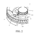
- FIG. 2 is a three-dimensional view of a gas stove according to an embodiment of the present invention
- FIG. 3 is a sectional view of a gas stove according to an embodiment of the present invention
- FIG. 4 is an enlarged view of Area B in FIG. 3 .
- the gas stove 1 includes an ignition needle 2 and a burner 3.
- the ignition needle 2 includes an ignition electrode 10 and a casing 20, the ignition electrode 10 includes an ignition head 11, the ignition head 11 includes a top-down radially tapered necking portion 110; and the casing 20 wraps the ignition electrode 10 with the ignition head 11 exposed.
- An ignition hole 300 is disposed on the burner 3, and electrical sparks generated by the ignition head 11 ignite gas ejected from the ignition hole 300.
- the ignition head 11 has an inverted cone shape.
- the casing 20 is made of ceramic.
- an inner fire hole 310 and an outer fire hole 320 are disposed on the burner 3, and the burner 3 includes an inner gas mixing chamber 31 for supplying gas for the inner fire hole 310.
- a projection portion 311 is formed outside the inner gas mixing chamber 31, and the ignition hole 300 is disposed on the projection portion 311.
- the ignition direction of the ignition head 11 is toward the ignition hole 300.
- the ignition head 11 further includes an ignition portion 111, and the ignition portion 111 is located at a position of the necking portion 110 toward the ignition hole 300 and having the maximum radial size.
- the projection portion 311 has an inclined plane 3111, and an outlet of the ignition hole 300 is located on the inclined plane 3111.
- a plane where an outlet end surface of the ignition hole 300 is located is defined as a first plane, and the first plane is the plane where the inclined plane 3111 is located.
- An included angle of the first plane and an axis of the ignition electrode 10 is ⁇ ; an edge of the necking portion 110 that is located on the axis of the ignition electrode 10, perpendicular to a cross section of the first plane, and close to the ignition hole 300 is defined as a first edge 1111, and an included angle of the first edge 1111 and the axis of the ignition electrode 10 is ⁇ ; and ⁇ and ⁇ satisfy the following formula: ⁇ , where the magnitude of ⁇ and ⁇ may be different according to specific designs, for example, in this embodiment, ⁇ is 15°, and ⁇ is 30°.
- the distance from the ignition portion 111 of the ignition head 11 to the first plane is the minimum, so electrical sparks are most likely generated at the ignition portion 111.
- the lower section of the necking portion 110 is farther away from the inclined plane 3111 (or the first plane), so the possibility that electrical sparks are generated at the lower section of the necking portion 110 is smaller. Therefore, the section of the ignition head 11 where electrical sparks are generated is uniquely and certainly at the ignition portion 111. Therefore, upon being powered for ignition, electrical sparks are definitely formed between the ignition portion 111 and the ignition hole 300, and the electrical sparks are on the path of the gas ejected from the ignition hole 300, so that gas ejected from the ignition hole 300 meets the electrical sparks and then is successfully ignited.
- the casing 20 can be designed to be lower, and the extension direction of the ignition hole 300 does not intersect the casing 20. In this way, after successful ignition, when the gas stove works normally, flames ejected from the ignition hole 300 will not burn the casing 20, which is beneficial to prolonging the service life of the ignition needle 2.
- the ignition head exposed from the ceramic casing has a columnar shape, if the casing is designed to be low, the lower section of the ignition head is closer to the plane where the outlet end surface of the ignition hole is located, the possibility that electrical sparks are generated is not reduced but increased. Therefore, electrical sparks may be generated at a section below the ignition head, while the electrical spark generation path is not on the path of the gas ejected from the ignition hole, so the ignition success rate is low, and the phenomenon of excessively long ignition time or unsuccessful ignition easily occurs.
- the casing 20 is lower than the outlet of the ignition hole 300, so that flames ejected from the ignition hole 300 will definitely burn the casing 20, and moreover, it is very convenient for the operator to determine whether the ignition needle 2 is correctly installed through measurement or even visual inspection.
- the extension direction of the ignition hole 300 intersects the necking portion 110, thereby ensuring that the electrical spark generation path is on the path of the gas ejected from the ignition hole 300.
- the ignition head 11 actually has an inverted truncated cone shape.
- the inverted truncated cone-shaped ignition head is not only more beneficial to processing and manufacturing, and after installation, regardless of which side of the ignition head 11 toward the ignition hole 300, the distance from the ignition portion 111 to the outlet end surface of the ignition hole 300 is the same.
- the ignition head can also be designed to have an inverted truncated pyramid shape or other similar shapes, but fool-proofing design is required, because when different sides of the ignition head are toward the ignition hole 300, the distance from the ignition portion to the outlet end surface of the ignition hole 300 is not always the same.
Landscapes
- Engineering & Computer Science (AREA)
- Chemical & Material Sciences (AREA)
- Combustion & Propulsion (AREA)
- Mechanical Engineering (AREA)
- General Engineering & Computer Science (AREA)
- Spark Plugs (AREA)
- Feeding And Controlling Fuel (AREA)
Abstract
Description
- The present invention relates to a household cooker or stove, and in particular, to an ignition needle for a gas stove and a gas stove having the ignition needle.
- Presently, most gas stoves available in the market adopt the manner of powering an ignition needle for igniting the gas, where the ignition direction of the ignition needle is generally towards a site near an ignition hole of the gas stove, and upon ignition, an instant high potential is generated at an end of an ignition electrode of the ignition needle, and breaks down air between the ignition head and metal around the ignition hole to form electrical sparks, so as to ignite the gas ejected from the ignition hole. In order to ensure that the end of the ignition electrode discharge, an insulating ceramic casing wrapping the ignition electrode is designed to be very high, so that merely the end of the ignition electrode is exposed from the ceramic casing. However, after successful ignition, when the gas stove works normally, the flames ejected from the ignition hole always burn the ceramic casing, and after frequent high-temperature burning and cooling process, the ceramic casing easily ruptures and even falls off, thus shortening the service life of the ignition needle. Because the insulating ceramic casing falls off, besides the section that is originally designed to be exposed, other sections of the electrode are exposed, and finally, the section where electrical spark is generated changes upon being powered for ignition, resulting in ignition failure, so it is necessary to replace the ignition needle with a new one. According to some other designs, the ignition electrode is bent towards a certain direction to define an ignition direction, so as to ensure that the end of the ignition electrode discharges, so that the height of the ceramic casing is reduced, thereby preventing the flames ejected from the ignition hole from burning the ceramic casing. However, in such a design, the exposed ignition electrode is every high, while the ignition electrode is thin and weak, and is easily bent or deviated when being hit, thereby influencing the ignition effect, especially when cleaning area surround a burner of the gas stove, the burner needs to be moved away from the working position and moved back after cleaning, and in the process, the ignition electrode is easily hit by the burner manufactured by a metal such as brass and bent or deviated.
- Unless there is sufficient evidence to support, the prior art described herein does not mean that the prior arts are well known to persons of ordinary skill in the art before the filing date of this application.
- In view of the disadvantages of ignition needles described above, main objectives of the present invention are to improve the ignition needles and provide a novel ignition needle for a gas stove and a gas stove having the ignition needle.
- The present invention adopts the following technical solutions to solve the technical problems. An ignition needle for a gas stove is provided, which includes an ignition electrode and a casing, where the ignition electrode includes an ignition head, and the ignition head includes a top-down radially tapered necking portion; the casing wraps the ignition electrode with the ignition head exposed. Herein, "top-down" is based on that the ignition needle is at the installation position and is in use. When the ignition needle is powered for ignition, electrical sparks are always formed between the ignition head and metal closest to the ignition head, and the section of the ignition head closest to the metal generates the electrical sparks. Since the necking portion is radially tapered, the lower section of the necking portion is farther away from the metal around the ignition needle, the possibility that electrical sparks are generated at the lower section of the necking portion is smaller. Therefore, a casing of the ignition needle can be designed to be lower, and after successful ignition, when the gas stove works normally, flames ejected from the ignition hole will not burn the casing, which is beneficial to prolonging the service life of the ignition needle.
- In a possible implementation manner of the present invention, the ignition head includes an ignition portion, where the ignition portion is located at a position of the necking portion having the maximum radial size in the ignition direction of the ignition head.
- In a possible implementation manner of the present invention, the section of the ignition head where electrical sparks are generated is uniquely and certainly at the ignition portion. Under normal conditions, the lower section of the necking portion is farther away from the metal around the ignition needle, so the possibility that electrical sparks are generated at the lower section of the necking portion is smaller, thus ensuring that the section where electrical sparks are generated each time is certainly at the ignition portion. By adopting the technical solution of the present invention, the ignition action can be executed more precisely, the ignition success rate is higher, thereby significantly reducing or preventing occurrence of the phenomenon of excessively long ignition time or unsuccessful ignition.
- In a possible implementation manner of the present invention, the ignition head has an inverted cone shape, so as to provide a technical solution with different technical conceptions.
- Based on considerations of ease of manufacturing, in order to enable the ignition needle of the present invention to be suitable for large-scale factory manufacturing and application, in a possible implementation manner of the present invention, the ignition head has an inverted truncated cone shape or an inverted truncated pyramid shape.
- In a possible implementation manner of the present invention, the radial size of the necking portion ranges from 2 mm to 8 mm, being beneficial to improving the anti-impact capability of the ignition head.
- In a possible implementation manner of the present invention, the ignition electrode includes a first neck and a second neck connected to the first neck, and the first neck is connected to the ignition head, where the diameter of the first neck is d1, the diameter of the second neck is d2, and d1 and d2 satisfy the following formula: d1≥d2. When d1≥d2, the radial size of the ignition electrode is gradually changed from top to bottom, namely, from the ignition head to the first neck and then to the second neck, so as to ensure the strength of the junction of the ignition head and the casing, and avoid significant reduction of strength due to sudden decrease in size at this section.
- In a possible implementation manner of the present invention, the first neck and the second neck are integrally formed; or the first neck and the second neck are individually formed and then connected together through assembling.
- In order to ensure the accuracy of the installation height of the ignition electrode, in a possible implementation manner of the present invention, the casing has a first accommodation portion and a second accommodation portion respectively matching the first neck and the second neck.
- In a possible implementation manner of the present invention, the first neck and the second neck are respectively fixed in the first accommodation portion and the second accommodation portion by binding.
- In a possible implementation manner of the present invention, the casing is made of ceramic.
- Based on the main objectives of the present invention, this application further provides a gas stove, where the gas stove includes the ignition needle described above.
- In a possible implementation manner of the present invention, the gas stove includes a burner, an ignition hole is disposed on the burner, and electrical sparks generated by the ignition head ignite gas ejected from the ignition hole.
- In a possible implementation manner of the present invention, the ignition direction of the ignition head is toward the ignition hole.
- In a possible implementation manner of the present invention, the extension direction of the ignition hole does not intersect the casing. Since the ignition needle of the present invention is adopted, the height of the casing can be reduced, so that the casing is not in the extension direction of the ignition hole. When the burner works normally, flames ejected from the ignition hole will not burn the casing, which is beneficial to prolonging the service life of the ignition needle.
- In a possible implementation manner of the present invention, the casing is lower than an outlet of the ignition hole.
- In a possible implementation manner of the present invention, the extension direction of the ignition hole intersects the necking portion. In this way, it can be ensured that gas meets with the electrical sparks on the path when being ejected from the ignition hole, and is ignited, which is beneficial to improving the ignition success rate.
- In a possible implementation manner of the present invention, an inner fire hole and an outer fire hole are disposed on the burner, the burner includes an inner gas mixing chamber for supplying gas for the inner fire hole, a projection portion is formed outside of the inner gas mixing chamber, and the ignition hole is disposed on the projection portion.
- In a possible implementation manner of the present invention, the projection portion has an inclined plane, and an outlet of the ignition hole is located on the inclined plane.
- In a possible implementation manner of the present invention, a plane where an outlet end surface of the ignition hole is located is defined as a first plane, and an included angle of the first plane and an axis of the ignition electrode is α; an edge of the necking portion that is located on the axis of the ignition electrode, perpendicular to a cross section of the first plane, and close to the ignition hole is defined as a first edge, and an included angle of the first edge and the axis of the ignition electrode is β; and α and β satisfy the following formula: α<β.
- The disclosure will become more fully understood from the detailed description given herein below for illustration only, and thus are not limitative of the disclosure, and wherein:
-
FIG. 1 is a schematic diagram of an ignition needle for a gas stove according to an embodiment of the present invention; -
FIG. 2 is a three-dimensional view of a gas stove according to an embodiment of the present invention; -
FIG. 3 is a sectional view of a gas stove according to an embodiment of the present invention; and -
FIG. 4 is an enlarged view of Area B inFIG. 3 . - In order to make the objectives, structures, features and effects of the present invention more comprehensible, the present invention is described in detail below through embodiments.
-
FIG. 1 is a schematic diagram of an ignition needle for a gas stove according to an embodiment of the present invention. The present invention provides anignition needle 2, used for ignition of a gas stove. Theignition needle 2 includes anignition electrode 10 and acasing 20, theignition electrode 10 includes anignition head 11, theignition head 11 includes a top-down radially taperednecking portion 110; and thecasing 20 wraps theignition electrode 10 with theignition head 11 exposed. - The
casing 20 of this embodiment is made of ceramic. Theignition head 11 has an inverted cone shape, and thenecking portion 110 extends through thewhole ignition head 11 from top to bottom. Definitely, according to specific design demands, one section of the ignition head can also be designed to have a necking portion. Theignition electrode 10 includes afirst neck 12 and asecond neck 13 connected to thefirst neck 12, and thefirst neck 12 is connected to theignition head 11, where the diameter of thefirst neck 12 is d1, the diameter of thesecond neck 13 is d2, and d1 and d2 satisfy the following formula: d1>d2. Thefirst neck 12 and thesecond neck 13 can be integrally formed, and can also be individually formed and then connected together through assembling. Thecasing 20 has afirst accommodation portion 21 and asecond accommodation portion 22 respectively matching thefirst neck 12 and thesecond neck 13. It can be imaged that the inner diameter of thefirst accommodation portion 21 is greater than that of thesecond accommodation portion 22, thus forming a step structure at the junction of thefirst accommodation portion 21 and thesecond accommodation portion 22, so that the ignition electrode can be accurately located, thereby ensuring the accuracy of the installation height of the ignition electrode, and being convenient for assembling of the ignition electrode. Herein, the installation height of the ignition electrode refers to the height of the ignition electrode exposed from the casing. In order to firmly fix the ignition electrode, thefirst neck 12 and thesecond neck 13 are respectively fixed in thefirst accommodation portion 21 and thesecond accommodation portion 22 by binding, so as to prevent the ignition electrode from being pulling out by mistake. - In this embodiment, the diameter of the top of the
ignition head 11 is approximately 5 mm, and the diameter of the bottom is approximately 3 mm; in other words, the diameter d1 of thefirst neck 12 approximately is 3 mm. The diameter d2 of thesecond neck 13 is equal to the diameter of an existing ignition electrode. Therefore, the strength of the ignition head having an inverted cone shape of this embodiment is significantly increased, and the anti-impact capability is improved, compared with the ignition head in the prior art. A large number of experiments show that the radial size of the neckingportion 110 ranging from 2 mm to 8 mm is available. Theignition head 11 includes anignition portion 111, and theignition portion 111 is located at a position of the neckingportion 110 having the maximum radial size in the ignition direction of theignition head 11. As shown inFIG. 1 , assuming that the ignition direction of theignition head 11 is toward the direction on the left of theignition head 11, theignition portion 111 is located at the left end of the inverted cone-shapedignition head 11, so that even if some dirt falls on theignition head 11, ignition will not be influenced. Under normal conditions, the lower section of the neckingportion 110 is farther away from the metal around theignition needle 2, so the possibility that electrical sparks are generated at the lower section of the neckingportion 110 is smaller. Therefore, the section of theignition head 11 where electrical sparks are generated is uniquely and certainly at theignition portion 111. In this way, the installed ignition needle can accurately perform the ignition action towards the preset ignition direction. On the other hand, since the possibility that electrical sparks are generated at the lower section of the neckingportion 110 is smaller, thecasing 20 can be designed to be lower, and after successful ignition, when the gas stove works normally, flames ejected from the ignition hole will not burn thecasing 20, which is beneficial to prolonging the service life of theignition needle 2. - Based on an overall inventive concept, the present invention further provides a gas stove. As shown in
FIG. 2 to FIG. 4 ,FIG. 2 is a three-dimensional view of a gas stove according to an embodiment of the present invention;FIG. 3 is a sectional view of a gas stove according to an embodiment of the present invention; andFIG. 4 is an enlarged view of Area B inFIG. 3 . Thegas stove 1 includes anignition needle 2 and aburner 3. Theignition needle 2 includes anignition electrode 10 and acasing 20, theignition electrode 10 includes anignition head 11, theignition head 11 includes a top-down radially taperednecking portion 110; and thecasing 20 wraps theignition electrode 10 with theignition head 11 exposed. Anignition hole 300 is disposed on theburner 3, and electrical sparks generated by theignition head 11 ignite gas ejected from theignition hole 300. As shown inFIG. 2 , specifically, in an embodiment, theignition head 11 has an inverted cone shape. Thecasing 20 is made of ceramic. - Referring to
FIG. 2 to FIG. 4 , aninner fire hole 310 and anouter fire hole 320 are disposed on theburner 3, and theburner 3 includes an innergas mixing chamber 31 for supplying gas for theinner fire hole 310. Aprojection portion 311 is formed outside the innergas mixing chamber 31, and theignition hole 300 is disposed on theprojection portion 311. The ignition direction of theignition head 11 is toward theignition hole 300. Theignition head 11 further includes anignition portion 111, and theignition portion 111 is located at a position of the neckingportion 110 toward theignition hole 300 and having the maximum radial size. Theprojection portion 311 has an inclinedplane 3111, and an outlet of theignition hole 300 is located on theinclined plane 3111. A plane where an outlet end surface of theignition hole 300 is located is defined as a first plane, and the first plane is the plane where theinclined plane 3111 is located. An included angle of the first plane and an axis of theignition electrode 10 is α; an edge of the neckingportion 110 that is located on the axis of theignition electrode 10, perpendicular to a cross section of the first plane, and close to theignition hole 300 is defined as a first edge 1111, and an included angle of the first edge 1111 and the axis of theignition electrode 10 is β; and α and β satisfy the following formula: α<β, where the magnitude of α and β may be different according to specific designs, for example, in this embodiment, α is 15°, and β is 30°. Though such a design, the distance from theignition portion 111 of theignition head 11 to the first plane is the minimum, so electrical sparks are most likely generated at theignition portion 111. Moreover, the lower section of the neckingportion 110 is farther away from the inclined plane 3111 (or the first plane), so the possibility that electrical sparks are generated at the lower section of the neckingportion 110 is smaller. Therefore, the section of theignition head 11 where electrical sparks are generated is uniquely and certainly at theignition portion 111. Therefore, upon being powered for ignition, electrical sparks are definitely formed between theignition portion 111 and theignition hole 300, and the electrical sparks are on the path of the gas ejected from theignition hole 300, so that gas ejected from theignition hole 300 meets the electrical sparks and then is successfully ignited. It can be seen that, this technical solution is beneficial to improving the ignition success rate and rapidly igniting the gas. By adopting theignition electrode 10 of the present invention, thecasing 20 can be designed to be lower, and the extension direction of theignition hole 300 does not intersect thecasing 20. In this way, after successful ignition, when the gas stove works normally, flames ejected from theignition hole 300 will not burn thecasing 20, which is beneficial to prolonging the service life of theignition needle 2. However, in the prior art, the ignition head exposed from the ceramic casing has a columnar shape, if the casing is designed to be low, the lower section of the ignition head is closer to the plane where the outlet end surface of the ignition hole is located, the possibility that electrical sparks are generated is not reduced but increased. Therefore, electrical sparks may be generated at a section below the ignition head, while the electrical spark generation path is not on the path of the gas ejected from the ignition hole, so the ignition success rate is low, and the phenomenon of excessively long ignition time or unsuccessful ignition easily occurs. - Because the interior of the
ignition hole 300 is not exposed, for the convenience of installation and design, thecasing 20 is lower than the outlet of theignition hole 300, so that flames ejected from theignition hole 300 will definitely burn thecasing 20, and moreover, it is very convenient for the operator to determine whether theignition needle 2 is correctly installed through measurement or even visual inspection. As a further improvement of the present invention, the extension direction of theignition hole 300 intersects the neckingportion 110, thereby ensuring that the electrical spark generation path is on the path of the gas ejected from theignition hole 300. - Referring to
FIG. 2 , theignition head 11 actually has an inverted truncated cone shape. The inverted truncated cone-shaped ignition head is not only more beneficial to processing and manufacturing, and after installation, regardless of which side of theignition head 11 toward theignition hole 300, the distance from theignition portion 111 to the outlet end surface of theignition hole 300 is the same. Definitely, according to the present invention, the ignition head can also be designed to have an inverted truncated pyramid shape or other similar shapes, but fool-proofing design is required, because when different sides of the ignition head are toward theignition hole 300, the distance from the ignition portion to the outlet end surface of theignition hole 300 is not always the same. - The present invention has been described with the relevant embodiments, but the embodiments are merely examples for implementing the present invention. It should be noted that the disclosed embodiments are not intended to limit the scope of the present invention. On the contrary, variations and modifications made without departing from the spirit and scope of the present invention shall fall within the protection scope of the present invention.
-
- 1.
- gas stove;
- 2.
- ignition needle;
- 3.
- burner;
- 10.
- ignition electrode;
- 11.
- ignition head;
- 110.
- necking portion;
- 111.
- ignition portion;
- 1111.
- first edge;
- 12.
- first neck;
- 13.
- second neck;
- 20.
- casing;
- 21.
- first accommodation portion;
- 22.
- second accommodation portion;
- 31.
- inner gas mixing chamber;
- 300.
- ignition hole;
- 310.
- inner fire hole;
- 320.
- outer fire hole;
- 311.
- projection portion;
- 3111.
- inclined plane.
Claims (15)
- An ignition needle for a gas stove (2), comprising an ignition electrode (10) and a casing (20), characterized in that,
the ignition electrode (10) comprises an ignition head (11), and the ignition head (11) comprises a top-down radially tapered necking portion (110); and
the casing (20) wraps the ignition electrode (10) with the ignition head (11) exposed. - The ignition needle (2) according to claim 1, characterized in that, the ignition head (11) comprises an ignition portion (111), and the ignition portion (111) is located at a position of the necking portion (110) having the maximum radial size in the ignition direction of the ignition head (11).
- The ignition needle (2) according to claim 2, characterized in that, the section of the ignition head (11) where electrical sparks are generated is uniquely and certainly at the ignition portion (111).
- The ignition needle (2) according to claim 1, characterized in that, the ignition head (11) has an inverted cone shape.
- The ignition needle (2) according to claim 4, characterized in that, the ignition head (11) has an inverted truncated cone shape or an inverted truncated pyramid shape.
- The ignition needle (2) according to claim 1, characterized in that, the radial size of the necking portion (110) ranges from 2 mm to 8 mm.
- The ignition needle (2) according to claim 1, characterized in that, the ignition electrode (10) comprises a first neck (12) and a second neck (13) connected to the first neck (12), and the first neck (12) is connected to the ignition head (11), wherein the diameter of the first neck (12) is d1, the diameter of the second neck (13) is d2, and d1 and d2 satisfy the following formula: d1≥d2.
- The ignition needle (2) according to claim 7, characterized in that, the first neck (12) and the second neck (13) are integrally formed; or the first neck (12) and the second neck (13) are individually formed and then connected together through assembling.
- The ignition needle (2) according to claim 7, characterized in that, the casing (20) has a first accommodation portion (21) and a second accommodation portion (22) respectively matching the first neck (12) and the second neck (13).
- The ignition needle (2) according to claim 9, characterized in that, the first neck (12) and the second neck (13) are respectively fixed in the first accommodation portion (21) and the second accommodation portion (22) by binding.
- The ignition needle (2) according to any one of claims 1 to 10, characterized in that, the casing (20) is made of ceramic.
- A gas stove (1), characterized by comprising the ignition needle (2) according to any one of the preceding claims.
- The gas stove (1) according to claim 12, characterized by comprising a burner (3), an ignition hole (300) being disposed on the burner (3), and electrical sparks generated by the ignition head (11) igniting gas ejected from the ignition hole (300).
- The gas stove (1) according to claim 13, characterized in that, the ignition direction of the ignition head (11) is toward the ignition hole (300).
- The gas stove (1) according to claim 13, characterized in that, the extension direction of the ignition hole (300) does not intersect the casing (20).
Applications Claiming Priority (1)
| Application Number | Priority Date | Filing Date | Title |
|---|---|---|---|
| CN201310483232.2A CN104566445B (en) | 2013-10-16 | 2013-10-16 | Ignition needle for gas stove and gas stove |
Publications (2)
| Publication Number | Publication Date |
|---|---|
| EP2868975A2 true EP2868975A2 (en) | 2015-05-06 |
| EP2868975A3 EP2868975A3 (en) | 2015-09-16 |
Family
ID=51753027
Family Applications (1)
| Application Number | Title | Priority Date | Filing Date |
|---|---|---|---|
| EP14188926.1A Withdrawn EP2868975A3 (en) | 2013-10-16 | 2014-10-15 | Ignition needle for gas stove and gas stove |
Country Status (2)
| Country | Link |
|---|---|
| EP (1) | EP2868975A3 (en) |
| CN (1) | CN104566445B (en) |
Cited By (5)
| Publication number | Priority date | Publication date | Assignee | Title |
|---|---|---|---|---|
| CN108119922A (en) * | 2018-01-31 | 2018-06-05 | 佛山市云米电器科技有限公司 | A kind of burner ignition pin and its assembly method convenient for assembling |
| CN110081471A (en) * | 2019-05-23 | 2019-08-02 | 山东小鸭集团小家电有限公司 | A kind of gas-cooker easy to use |
| CN111550825A (en) * | 2020-05-29 | 2020-08-18 | 中山百得厨卫有限公司 | Burner ignition needle induction needle mounting assembly |
| CN116066825A (en) * | 2023-01-18 | 2023-05-05 | 宁波方太厨具有限公司 | stove burner |
| CN117628529A (en) * | 2023-11-28 | 2024-03-01 | 宝应县华源电器有限公司 | An ultra-sensitive ultra-high temperature non-oxide ceramic ignition needle that facilitates heat dissipation |
Families Citing this family (2)
| Publication number | Priority date | Publication date | Assignee | Title |
|---|---|---|---|---|
| CN109595587B (en) * | 2017-09-30 | 2024-01-16 | 宁波方太厨具有限公司 | Ignition needle and gas burner using same |
| CN112178699B (en) * | 2019-07-05 | 2023-10-27 | 博西华电器(江苏)有限公司 | Gas stove burners, gas stoves and gas stove ignition devices |
Family Cites Families (12)
| Publication number | Priority date | Publication date | Assignee | Title |
|---|---|---|---|---|
| FR2329088A1 (en) * | 1975-10-21 | 1977-05-20 | Djeddah Jacques | CANDLE OR IGNITION ELECTRODE FOR BURNER |
| GB1587002A (en) * | 1978-03-02 | 1981-03-25 | Kigass Eng Ltd | Electrode assemblies |
| ZA947260B (en) * | 1993-09-22 | 1995-05-23 | Utilux Pty Ltd | Igniter for a fluid burning appliance |
| WO2000052391A1 (en) * | 1999-02-26 | 2000-09-08 | Utilux Pty. Limited | Improved gas igniter |
| JP4945284B2 (en) * | 2007-03-29 | 2012-06-06 | リンナイ株式会社 | Gas stove |
| CN201615515U (en) * | 2009-11-30 | 2010-10-27 | 陈立德 | burner with ignition pin |
| CN102109179B (en) * | 2009-12-24 | 2014-09-24 | 博西华电器(江苏)有限公司 | Ignition needles for gas stove and gas stove employing same |
| CN201652366U (en) * | 2010-04-29 | 2010-11-24 | 宁波方太厨具有限公司 | Pressure balancing mixed gas chamber of combustor and combustor |
| CN201875742U (en) * | 2010-06-30 | 2011-06-22 | 宝应县华源电器有限公司 | Ignition needle |
| CN102692018B (en) * | 2011-03-22 | 2016-08-03 | 博西华电器(江苏)有限公司 | Gas-cooker |
| CN202813471U (en) * | 2012-09-12 | 2013-03-20 | 山西三益科技有限公司 | Ignition device for gas cooking appliance |
| CN203190465U (en) * | 2013-04-28 | 2013-09-11 | 杭州奥普博朗尼厨卫科技有限公司 | Ignition needle fixing structure easy to detach and mount |
-
2013
- 2013-10-16 CN CN201310483232.2A patent/CN104566445B/en not_active Expired - Fee Related
-
2014
- 2014-10-15 EP EP14188926.1A patent/EP2868975A3/en not_active Withdrawn
Non-Patent Citations (1)
| Title |
|---|
| None |
Cited By (5)
| Publication number | Priority date | Publication date | Assignee | Title |
|---|---|---|---|---|
| CN108119922A (en) * | 2018-01-31 | 2018-06-05 | 佛山市云米电器科技有限公司 | A kind of burner ignition pin and its assembly method convenient for assembling |
| CN110081471A (en) * | 2019-05-23 | 2019-08-02 | 山东小鸭集团小家电有限公司 | A kind of gas-cooker easy to use |
| CN111550825A (en) * | 2020-05-29 | 2020-08-18 | 中山百得厨卫有限公司 | Burner ignition needle induction needle mounting assembly |
| CN116066825A (en) * | 2023-01-18 | 2023-05-05 | 宁波方太厨具有限公司 | stove burner |
| CN117628529A (en) * | 2023-11-28 | 2024-03-01 | 宝应县华源电器有限公司 | An ultra-sensitive ultra-high temperature non-oxide ceramic ignition needle that facilitates heat dissipation |
Also Published As
| Publication number | Publication date |
|---|---|
| CN104566445B (en) | 2019-04-26 |
| EP2868975A3 (en) | 2015-09-16 |
| CN104566445A (en) | 2015-04-29 |
Similar Documents
| Publication | Publication Date | Title |
|---|---|---|
| US8890396B2 (en) | Spark plug for a gas-operated internal combustion engine | |
| CN103746291B (en) | a spark plug | |
| CN104566445A (en) | Ignition needle for gas stove and gas stove | |
| US9972979B2 (en) | Prechamber spark plug for igniting a fuel-air mixture in an internal combustion engine | |
| US8047172B2 (en) | Plasma jet ignition plug | |
| CN103779788B (en) | A kind of spark plug and use the ignition system of internal combustion engine of this spark plug | |
| US20210399532A1 (en) | Spark plug | |
| CN102080834A (en) | Burner with ignition needle sheath | |
| JP6041824B2 (en) | Spark plug and ignition system | |
| CN102948024B (en) | Plasma jet spark plug | |
| JP4942701B2 (en) | Stove burner | |
| CN114963181A (en) | Combustor and contain its cooking utensils | |
| CN107062309A (en) | A kind of infrared burner for improving sparking mode | |
| CN206291207U (en) | An ignition device for an infrared burner | |
| CN204253189U (en) | Macro-energy long-life semiconductor discharge plug discharge end structure | |
| CN109595587B (en) | Ignition needle and gas burner using same | |
| CN220852225U (en) | Quenching and protecting assembly | |
| CN210373578U (en) | Ion needle and furnace end | |
| CN220205823U (en) | Ignition needle assembly and gas stove | |
| CN221122291U (en) | Electrode needle and gas stove | |
| CN220506768U (en) | Novel ignition needle and combustor | |
| CN222887402U (en) | A double-head ignition device for a gas furnace | |
| CN222732854U (en) | Ignition device, combustor and gas stove | |
| CN219014379U (en) | Electrode needle and gas stove | |
| CN113898946B (en) | A gas stove head with built-in fire starter |
Legal Events
| Date | Code | Title | Description |
|---|---|---|---|
| PUAI | Public reference made under article 153(3) epc to a published international application that has entered the european phase |
Free format text: ORIGINAL CODE: 0009012 |
|
| 17P | Request for examination filed |
Effective date: 20141015 |
|
| AK | Designated contracting states |
Kind code of ref document: A2 Designated state(s): AL AT BE BG CH CY CZ DE DK EE ES FI FR GB GR HR HU IE IS IT LI LT LU LV MC MK MT NL NO PL PT RO RS SE SI SK SM TR |
|
| AX | Request for extension of the european patent |
Extension state: BA ME |
|
| PUAL | Search report despatched |
Free format text: ORIGINAL CODE: 0009013 |
|
| RIN1 | Information on inventor provided before grant (corrected) |
Inventor name: WU, JINHUA Inventor name: YOU, CHAOLIN Inventor name: KAFALI, ZEKI |
|
| AK | Designated contracting states |
Kind code of ref document: A3 Designated state(s): AL AT BE BG CH CY CZ DE DK EE ES FI FR GB GR HR HU IE IS IT LI LT LU LV MC MK MT NL NO PL PT RO RS SE SI SK SM TR |
|
| AX | Request for extension of the european patent |
Extension state: BA ME |
|
| RIC1 | Information provided on ipc code assigned before grant |
Ipc: F23Q 3/00 20060101ALI20150813BHEP Ipc: F24C 3/10 20060101AFI20150813BHEP |
|
| R17P | Request for examination filed (corrected) |
Effective date: 20160316 |
|
| RBV | Designated contracting states (corrected) |
Designated state(s): AL AT BE BG CH CY CZ DE DK EE ES FI FR GB GR HR HU IE IS IT LI LT LU LV MC MK MT NL NO PL PT RO RS SE SI SK SM TR |
|
| 17Q | First examination report despatched |
Effective date: 20180918 |
|
| GRAP | Despatch of communication of intention to grant a patent |
Free format text: ORIGINAL CODE: EPIDOSNIGR1 |
|
| INTG | Intention to grant announced |
Effective date: 20191108 |
|
| STAA | Information on the status of an ep patent application or granted ep patent |
Free format text: STATUS: THE APPLICATION IS DEEMED TO BE WITHDRAWN |
|
| 18D | Application deemed to be withdrawn |
Effective date: 20200603 |