EP2868940A2 - Dowel element - Google Patents
Dowel element Download PDFInfo
- Publication number
- EP2868940A2 EP2868940A2 EP20140190336 EP14190336A EP2868940A2 EP 2868940 A2 EP2868940 A2 EP 2868940A2 EP 20140190336 EP20140190336 EP 20140190336 EP 14190336 A EP14190336 A EP 14190336A EP 2868940 A2 EP2868940 A2 EP 2868940A2
- Authority
- EP
- European Patent Office
- Prior art keywords
- dowel
- fretting
- head portion
- relief
- dowel element
- Prior art date
- Legal status (The legal status is an assumption and is not a legal conclusion. Google has not performed a legal analysis and makes no representation as to the accuracy of the status listed.)
- Granted
Links
Images


Classifications
-
- F—MECHANICAL ENGINEERING; LIGHTING; HEATING; WEAPONS; BLASTING
- F16—ENGINEERING ELEMENTS AND UNITS; GENERAL MEASURES FOR PRODUCING AND MAINTAINING EFFECTIVE FUNCTIONING OF MACHINES OR INSTALLATIONS; THERMAL INSULATION IN GENERAL
- F16D—COUPLINGS FOR TRANSMITTING ROTATION; CLUTCHES; BRAKES
- F16D1/00—Couplings for rigidly connecting two coaxial shafts or other movable machine elements
- F16D1/06—Couplings for rigidly connecting two coaxial shafts or other movable machine elements for attachment of a member on a shaft or on a shaft-end
- F16D1/076—Couplings for rigidly connecting two coaxial shafts or other movable machine elements for attachment of a member on a shaft or on a shaft-end by clamping together two faces perpendicular to the axis of rotation, e.g. with bolted flanges
-
- F—MECHANICAL ENGINEERING; LIGHTING; HEATING; WEAPONS; BLASTING
- F16—ENGINEERING ELEMENTS AND UNITS; GENERAL MEASURES FOR PRODUCING AND MAINTAINING EFFECTIVE FUNCTIONING OF MACHINES OR INSTALLATIONS; THERMAL INSULATION IN GENERAL
- F16D—COUPLINGS FOR TRANSMITTING ROTATION; CLUTCHES; BRAKES
- F16D1/00—Couplings for rigidly connecting two coaxial shafts or other movable machine elements
- F16D1/02—Couplings for rigidly connecting two coaxial shafts or other movable machine elements for connecting two abutting shafts or the like
- F16D1/033—Couplings for rigidly connecting two coaxial shafts or other movable machine elements for connecting two abutting shafts or the like by clamping together two faces perpendicular to the axis of rotation, e.g. with bolted flanges
-
- F—MECHANICAL ENGINEERING; LIGHTING; HEATING; WEAPONS; BLASTING
- F16—ENGINEERING ELEMENTS AND UNITS; GENERAL MEASURES FOR PRODUCING AND MAINTAINING EFFECTIVE FUNCTIONING OF MACHINES OR INSTALLATIONS; THERMAL INSULATION IN GENERAL
- F16B—DEVICES FOR FASTENING OR SECURING CONSTRUCTIONAL ELEMENTS OR MACHINE PARTS TOGETHER, e.g. NAILS, BOLTS, CIRCLIPS, CLAMPS, CLIPS OR WEDGES; JOINTS OR JOINTING
- F16B2200/00—Constructional details of connections not covered for in other groups of this subclass
- F16B2200/50—Flanged connections
- F16B2200/506—Flanged connections bolted or riveted
-
- F—MECHANICAL ENGINEERING; LIGHTING; HEATING; WEAPONS; BLASTING
- F16—ENGINEERING ELEMENTS AND UNITS; GENERAL MEASURES FOR PRODUCING AND MAINTAINING EFFECTIVE FUNCTIONING OF MACHINES OR INSTALLATIONS; THERMAL INSULATION IN GENERAL
- F16B—DEVICES FOR FASTENING OR SECURING CONSTRUCTIONAL ELEMENTS OR MACHINE PARTS TOGETHER, e.g. NAILS, BOLTS, CIRCLIPS, CLAMPS, CLIPS OR WEDGES; JOINTS OR JOINTING
- F16B35/00—Screw-bolts; Stay-bolts; Screw-threaded studs; Screws; Set screws
- F16B35/04—Screw-bolts; Stay-bolts; Screw-threaded studs; Screws; Set screws with specially-shaped head or shaft in order to fix the bolt on or in an object
- F16B35/041—Specially-shaped shafts
- F16B35/048—Specially-shaped necks
-
- Y—GENERAL TAGGING OF NEW TECHNOLOGICAL DEVELOPMENTS; GENERAL TAGGING OF CROSS-SECTIONAL TECHNOLOGIES SPANNING OVER SEVERAL SECTIONS OF THE IPC; TECHNICAL SUBJECTS COVERED BY FORMER USPC CROSS-REFERENCE ART COLLECTIONS [XRACs] AND DIGESTS
- Y10—TECHNICAL SUBJECTS COVERED BY FORMER USPC
- Y10T—TECHNICAL SUBJECTS COVERED BY FORMER US CLASSIFICATION
- Y10T29/00—Metal working
- Y10T29/49—Method of mechanical manufacture
- Y10T29/49826—Assembling or joining
Definitions
- the subject matter disclosed herein relates to a dowel element and, more particularly, to a dowel bolt or dowel pin with an anti-fretting relief.
- Dowel bolts are used to fasten structural components together in an axial direction and to provide for an ability to transmit shear along the transverse dimension. Indeed, they are often used, for example, to couple a hub to an engine shaft in an aircraft engine. Under cyclic loads, however, it has been found that there may be a zone of the dowel bolt that will see sufficient load and motion to generate fretting damage. In the case of the hub and engine shaft coupling, this zone is located at a particular part of the dowel bolt in accordance with the direction of the rotation of the engine shaft.
- a dowel element includes a shank portion including first and second mating parts.
- One of the first and second mating parts includes a first exterior surface and is formed to define an anti-fretting relief including a second exterior surface recessed from the first exterior surface in a radial dimension.
- a dowel bolt includes a head portion and a shank portion extending from the head portion and including an engagement part and first and second mating parts sequentially arranged between the head portion and the engagement part to mate with first and second mated elements, respectively, with the engagement part and the head portion disposed to tighten the first and second mated elements together.
- One of the first and second mating parts includes a first exterior surface for abutment with an interior surface of the corresponding one of the first and second mated elements and is formed to define an anti-fretting relief including a second exterior surface recessed from the first exterior surface and the interior surface in a radial dimension.
- a method of providing a dowel bolt with fretting relief includes forming the dowel bolt with a head portion and a shank portion extending from the head portion, defining along the shank portion an engagement part and first and second mating parts sequentially arranged between the head portion and the engagement part to mate with first and second mated elements, respectively, with the engagement part and the head portion disposed to tighten the first and second mated elements together and defining an anti-fretting relief along one of the first and second mating parts where a fretting zone is expected to exist due to mating between the first and second mating parts and the first and second mated elements, respectively.
- a dowel element is provided and includes an anti-fretting relief in an area of expected fretting damage.
- This fretting relief is designed to avoid contact between the dowel element and the mating part in the area where the fretting conditions exist.
- This feature can be indexed to the proper position since dowel elements are normally press-fit in the mating part where the fretting condition occurs.
- the feature is a slight undercut of approximately 0.005 inches (0.127 mm), which will be sufficient to avoid the contact while not resulting in a significant structural stress concentration due to the discontinuity in the surface of the dowel element diameter. It is expected that the dowel element with the anti-fretting relief will result in an extended lifetime of the dowel element and will permit the avoidance of costly replacements.
- a dowel element 10 is provided and is configured for use in, for example, a coupling 11 of a dynamic or electro-dynamic machine 12.
- the coupling 11 may be provided between a first mated element, such as a hub element 13, and a second mated element, such as an engine shaft 14.
- the engine shaft 14 may be, in turn, coupled to a right or left turning propeller and the turning of the propeller causes torque to be applied to the coupling 11 in first or second directions, respectively.
- the dowel element 10 may be provided as a dowel bolt (see FIG. 2 ) or a dowel pin (see FIG. 6 ).
- the dowel element 10 includes a head portion and threading to be described below and cooperates with a nut 15 to tighten the first and second mated elements (i.e., the hub element 13 and the engine shaft 14) together.
- the dowel element 10 does not include a head portion or threading.
- the dowel element 10 further serves to transmit the applied torque along the assembly centerline 17, which may be defined in substantially in parallel with a longitudinal axis 16 of the dowel element 10.
- the coupling 11 may be provided with a plurality of dowel elements 10 arrayed in a circular configuration 100 about the assembly centerline 17.
- the dowel elements 10 are illustrated as being dowel bolts but it is to be understood that dowel elements 10 could be provided as dowel bolts, dowel pins, a mixture of dowel bolts and dowel pins or a mixture of regular bolts and dowel pins.
- the circular configuration is not required, however, and it is understood that other regular and irregular configurations are possible.
- the coupling 11 is disposed to experience an application of torque in either the clockwise or counter clockwise direction.
- the hub element 13 is formed to define a through-hole 130 at the coupling 11 and the engine shaft 14 is similarly formed to define a through-hole 140 at the coupling 11.
- the dowel element 10 is illustrated as a dowel bolt and includes a head portion 20 and a shank portion 30.
- the head portion 20 may be provided with a polygonal or angular shape and is wider than the through-holes 130 and 140.
- the shank portion 30 is sized to be press-fit in the through-hole 130 and clearance fit in the through hole 140 and extends from the head portion 10 along the longitudinal axis 16.
- the shank portion 30 includes an engagement part 31, a first mating part 32 and a second mating part 33.
- the first and second mating parts 32 and 33 are sequentially arranged between the head portion 20 and the engagement part 31 with the first mating part 32 relatively close to the head portion 20 and the second mating part 33 relatively remote from the head portion 20.
- the dowel element 10 is provided as a dowel pin, the head portion 20 and the engagement part 31 would not be included.
- the dowel element 10 further includes an anti-fretting relief 40.
- the anti-fretting relief 40 may be defined at one of the first and second mating parts 32 and 33. For the purposes of clarity and brevity, however, it will be assumed that the anti-fretting relief 40 is defined at the first mating part 32.
- the shank portion 30 extends through the through-holes 130 and 140 such that the engagement part 31 is exposed beyond the engine shaft 14 and such that the first mating part 32 is disposed to mate with the hub element 13 with a press fit and the second mating part 33 is disposed to mate with the engine shaft 14 with a clearance fit.
- a thickness of the first mating part 32 along the longitudinal axis 16 is substantially similar to a width of the hub element 13 and a thickness of the second mating part 33 along the longitudinal axis 16 is substantially similar to a width of the engine shaft 14.
- a diameter of the first mating part 32 may be slightly larger than a width of the through-hole 130 thereby defining the press fit relationship between the first mating part 32 and the hub element 13.
- a diameter of the second mating part 33 may be slightly smaller than a width of the through-hole 140 thereby defining the clearance fit between the second mating part 33 and the engine shaft 14.
- the engagement part 31 may include exterior threading 310 that is engageable with interior threading of the nut 15 to draw the head portion 20 toward the nut 15. With the head portion 20 abutting an exterior surface of the hub element 13 and the nut 15 abutting an exterior surface of the engine shaft 14, this tightening serves to tighten the hub element 13 and the engine shaft 14 toward one another.
- a cyclic loading field may be defined at the coupling 11 and, more particularly, at the location where the anti-fretting relief 40 is defined.
- the anti-fretting relief 40 is provided in this location, contact between the hub element 13 and the first mating part 32 at the anti-fretting relief 40 is eliminated while the first exterior facing surface 320 continues to abut the interior facing surface 321 of the hub element 13. The elimination of this contact prevents the fretting damage associated with premature fatigue failure.
- the anti-fretting relief 40 may be defined along an interface between the first and second mating parts 32 and 33 and includes first and second edges 41, a circumferential sidewall 42 and a second exterior surface 43.
- the first and second edges 41 delimit opposite circumferential ends of the anti-fretting relief 40 and the circumferential sidewall 42 delimits an axial end of the anti-fretting relief 40, which is opposite the axial end of the first mating part 32 where the first mating part 32 interfaces with the second mating part 33.
- the second exterior surface 43 runs along the first and second edges 41 and the circumferential sidewall 42 and is formed to be recessed from the first exterior surface 320 and from the interior facing surface 321 of the hub element 13 in a radial dimension R (see FIG. 4 ).
- the first exterior surface 320 may have a substantially cylindrical shape.
- the anti-fretting relief 40 extends along an arc-segment of the first exterior surface 320. This arc-segment may be approximately 120 degrees.
- the anti-fretting relief 40 may be approximately 0.005 inches (0.127 mm) deep (i.e., along the circumferential sidewall 42) and 0.11 inches (0.279 mm) wide (i.e., along the first and second edges 41).
- a method of providing a dowel element with fretting relief as described above includes forming the dowel element with a head portion and a shank portion extending from the head portion and defining along the shank portion an engagement part and first and second mating parts sequentially arranged between the head portion and the engagement part to mate with first and second mated elements, respectively, with the engagement part and the head portion disposed to tighten the first and second mated elements together.
- the method further includes defining an anti-fretting relief along one of the first and second mating parts where a fretting zone is expected to exist due to mating between the first and second mating parts and the first and second mated elements, respectively.
- the anti-fretting relief may be machined.
- the method may include determining where the fretting zone is expected to exist by for example inspecting a used dowel element.
- the description provided above generally relates to dowel elements 10 provided as a dowel bolts but it is to be understood that the dowel elements 10 may be provided as dowel pins as well.
- the dowel element 10 would not include the head portion 20 or the engagement part 31 and would not be cooperative with nut 15. Nevertheless, the dowel element 10 provided as a dowel pin would still include a first mating part 32 disposed with a press-fit with hub element 13 and second mating part 33 disposed with a clearance fit with engine shaft 14. As above, the anti-fretting relief 40 would remain disposed at the first mating part 32.
- a dowel pin can be used to transmit torque without clamping.
- regular bolts would clamp the parts together and the dowel pins would transmit torque.
- the dowel element 10 may include a timing device 50 so that the anti-fretting relief 40 can be correctly oriented.
- the timing device 50 may be provided in the head portion 20 or the engagement part 31.
Landscapes
- Engineering & Computer Science (AREA)
- General Engineering & Computer Science (AREA)
- Mechanical Engineering (AREA)
- Connection Of Plates (AREA)
- Mutual Connection Of Rods And Tubes (AREA)
- Gripping On Spindles (AREA)
Abstract
Description
- The subject matter disclosed herein relates to a dowel element and, more particularly, to a dowel bolt or dowel pin with an anti-fretting relief.
- Dowel bolts (and dowel pins) are used to fasten structural components together in an axial direction and to provide for an ability to transmit shear along the transverse dimension. Indeed, they are often used, for example, to couple a hub to an engine shaft in an aircraft engine. Under cyclic loads, however, it has been found that there may be a zone of the dowel bolt that will see sufficient load and motion to generate fretting damage. In the case of the hub and engine shaft coupling, this zone is located at a particular part of the dowel bolt in accordance with the direction of the rotation of the engine shaft.
- It has been seen that if the fretting damage is in a cyclic tensile stress field, premature fatigue failure of the dowel bolt may occur due to significant reductions in fatigue strength due to the fretted surface condition.
- According to one aspect of the invention, a dowel element is provided and includes a shank portion including first and second mating parts. One of the first and second mating parts includes a first exterior surface and is formed to define an anti-fretting relief including a second exterior surface recessed from the first exterior surface in a radial dimension.
- According to another aspect of the invention, a dowel bolt is provided and includes a head portion and a shank portion extending from the head portion and including an engagement part and first and second mating parts sequentially arranged between the head portion and the engagement part to mate with first and second mated elements, respectively, with the engagement part and the head portion disposed to tighten the first and second mated elements together. One of the first and second mating parts includes a first exterior surface for abutment with an interior surface of the corresponding one of the first and second mated elements and is formed to define an anti-fretting relief including a second exterior surface recessed from the first exterior surface and the interior surface in a radial dimension.
- According to yet another aspect of the invention, a method of providing a dowel bolt with fretting relief is provided and includes forming the dowel bolt with a head portion and a shank portion extending from the head portion, defining along the shank portion an engagement part and first and second mating parts sequentially arranged between the head portion and the engagement part to mate with first and second mated elements, respectively, with the engagement part and the head portion disposed to tighten the first and second mated elements together and defining an anti-fretting relief along one of the first and second mating parts where a fretting zone is expected to exist due to mating between the first and second mating parts and the first and second mated elements, respectively.
- These and other advantages and features will become more apparent from the following description taken in conjunction with the drawings.
- The subject matter, which is regarded as the invention, is particularly pointed out and distinctly claimed in the claims at the conclusion of the specification. The foregoing and other features, and advantages of the invention are apparent from the following detailed description taken in conjunction with the accompanying drawings in which:
-
FIG. 1 is an end view of a series of dowel elements in a hub and engine shaft coupling; -
FIG. 2 is a schematic side view of a dowel element provided as a dowel bolt in a hub and engine shaft coupling along line A-A ofFIG. 1 ; -
FIG. 3 is a cross-sectional view of a portion of the dowel element along lines B-B ofFIG. 2 ; -
FIG. 4 is a cross-sectional view of another portion of the dowel element along lines C-C ofFIG. 2 ; -
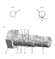
FIG. 5 is a perspective view of the dowel element ofFIG. 2 in accordance with embodiments; and -
FIG. 6 is a schematic side view of a dowel element provided as a dowel pin in a hub and engine shaft coupling. - The detailed description explains embodiments of the invention, together with advantages and features, by way of example with reference to the drawings.
- As will be described below, a dowel element is provided and includes an anti-fretting relief in an area of expected fretting damage. This fretting relief is designed to avoid contact between the dowel element and the mating part in the area where the fretting conditions exist. This feature can be indexed to the proper position since dowel elements are normally press-fit in the mating part where the fretting condition occurs. The feature is a slight undercut of approximately 0.005 inches (0.127 mm), which will be sufficient to avoid the contact while not resulting in a significant structural stress concentration due to the discontinuity in the surface of the dowel element diameter. It is expected that the dowel element with the anti-fretting relief will result in an extended lifetime of the dowel element and will permit the avoidance of costly replacements.
- With reference to
FIGS. 1-5 , adowel element 10 is provided and is configured for use in, for example, acoupling 11 of a dynamic or electro-dynamic machine 12. In one exemplary embodiment, which will be described herein for the purposes of clarity and brevity, thecoupling 11 may be provided between a first mated element, such as ahub element 13, and a second mated element, such as anengine shaft 14. Theengine shaft 14 may be, in turn, coupled to a right or left turning propeller and the turning of the propeller causes torque to be applied to thecoupling 11 in first or second directions, respectively. - The
dowel element 10 may be provided as a dowel bolt (seeFIG. 2 ) or a dowel pin (seeFIG. 6 ). In the former case, where thedowel element 10 is a dowel bolt, thedowel element 10 includes a head portion and threading to be described below and cooperates with anut 15 to tighten the first and second mated elements (i.e., thehub element 13 and the engine shaft 14) together. In the latter case, wherein thedowel element 10 is a dowel pin, thedowel element 10 does not include a head portion or threading. In either case, thedowel element 10 further serves to transmit the applied torque along theassembly centerline 17, which may be defined in substantially in parallel with alongitudinal axis 16 of thedowel element 10. - As shown in
FIG. 1 , thecoupling 11 may be provided with a plurality ofdowel elements 10 arrayed in acircular configuration 100 about theassembly centerline 17. Thedowel elements 10 are illustrated as being dowel bolts but it is to be understood thatdowel elements 10 could be provided as dowel bolts, dowel pins, a mixture of dowel bolts and dowel pins or a mixture of regular bolts and dowel pins. The circular configuration is not required, however, and it is understood that other regular and irregular configurations are possible. In each configuration, thecoupling 11 is disposed to experience an application of torque in either the clockwise or counter clockwise direction. - As shown in
FIG. 2 , thehub element 13 is formed to define a through-hole 130 at thecoupling 11 and theengine shaft 14 is similarly formed to define a through-hole 140 at thecoupling 11. As shown, thedowel element 10 is illustrated as a dowel bolt and includes ahead portion 20 and ashank portion 30. Thehead portion 20 may be provided with a polygonal or angular shape and is wider than the through-holes shank portion 30 is sized to be press-fit in the through-hole 130 and clearance fit in the throughhole 140 and extends from thehead portion 10 along thelongitudinal axis 16. Theshank portion 30 includes anengagement part 31, afirst mating part 32 and asecond mating part 33. The first andsecond mating parts head portion 20 and theengagement part 31 with thefirst mating part 32 relatively close to thehead portion 20 and thesecond mating part 33 relatively remote from thehead portion 20. - As noted above, where the
dowel element 10 is provided as a dowel pin, thehead portion 20 and theengagement part 31 would not be included. - In the case of the dowel bolt or the dowel pin, the
dowel element 10 further includes ananti-fretting relief 40. In accordance with various embodiments, theanti-fretting relief 40 may be defined at one of the first andsecond mating parts anti-fretting relief 40 is defined at thefirst mating part 32. - Where the
dowel element 10 is provided as the dowel bolt and is installed in thecoupling 11, theshank portion 30 extends through the through-holes engagement part 31 is exposed beyond theengine shaft 14 and such that thefirst mating part 32 is disposed to mate with thehub element 13 with a press fit and thesecond mating part 33 is disposed to mate with theengine shaft 14 with a clearance fit. In accordance with embodiments, a thickness of thefirst mating part 32 along thelongitudinal axis 16 is substantially similar to a width of thehub element 13 and a thickness of thesecond mating part 33 along thelongitudinal axis 16 is substantially similar to a width of theengine shaft 14. In addition, a diameter of thefirst mating part 32 may be slightly larger than a width of the through-hole 130 thereby defining the press fit relationship between thefirst mating part 32 and thehub element 13. By contrast, a diameter of thesecond mating part 33 may be slightly smaller than a width of the through-hole 140 thereby defining the clearance fit between thesecond mating part 33 and theengine shaft 14. As such, a firstexterior facing surface 320 of thefirst mating part 32 tightly abuts an interior facingsurface 321 of thehub element 13 except at theanti-fretting relief 40 and anexterior facing surface 330 of thesecond mating part 33 loosely abuts or is separate from an interior facingsurface 331 of theengine shaft 14. - The
engagement part 31 may includeexterior threading 310 that is engageable with interior threading of thenut 15 to draw thehead portion 20 toward thenut 15. With thehead portion 20 abutting an exterior surface of thehub element 13 and thenut 15 abutting an exterior surface of theengine shaft 14, this tightening serves to tighten thehub element 13 and theengine shaft 14 toward one another. - Due to the rotating of the propeller to which the
engine shaft 14 is connected, a cyclic loading field may be defined at thecoupling 11 and, more particularly, at the location where theanti-fretting relief 40 is defined. As such, in the absence of theanti-fretting relief 40, premature fatigue failure of thedowel element 10 could occur due to fretting damage caused by the cyclic loading field and the cyclic tensile field in the dowel bolt. However, since theanti-fretting relief 40 is provided in this location, contact between thehub element 13 and thefirst mating part 32 at theanti-fretting relief 40 is eliminated while the firstexterior facing surface 320 continues to abut theinterior facing surface 321 of thehub element 13. The elimination of this contact prevents the fretting damage associated with premature fatigue failure. - As shown in
FIGS. 1- 5 , theanti-fretting relief 40 may be defined along an interface between the first andsecond mating parts second edges 41, acircumferential sidewall 42 and a secondexterior surface 43. The first andsecond edges 41 delimit opposite circumferential ends of theanti-fretting relief 40 and thecircumferential sidewall 42 delimits an axial end of theanti-fretting relief 40, which is opposite the axial end of thefirst mating part 32 where thefirst mating part 32 interfaces with thesecond mating part 33. The secondexterior surface 43 runs along the first andsecond edges 41 and thecircumferential sidewall 42 and is formed to be recessed from the firstexterior surface 320 and from theinterior facing surface 321 of thehub element 13 in a radial dimension R (seeFIG. 4 ). - In accordance with embodiments, the first
exterior surface 320 may have a substantially cylindrical shape. In these cases, theanti-fretting relief 40 extends along an arc-segment of the firstexterior surface 320. This arc-segment may be approximately 120 degrees. In addition, theanti-fretting relief 40 may be approximately 0.005 inches (0.127 mm) deep (i.e., along the circumferential sidewall 42) and 0.11 inches (0.279 mm) wide (i.e., along the first and second edges 41). - In accordance with further aspects, a method of providing a dowel element with fretting relief as described above is provided and includes forming the dowel element with a head portion and a shank portion extending from the head portion and defining along the shank portion an engagement part and first and second mating parts sequentially arranged between the head portion and the engagement part to mate with first and second mated elements, respectively, with the engagement part and the head portion disposed to tighten the first and second mated elements together. The method further includes defining an anti-fretting relief along one of the first and second mating parts where a fretting zone is expected to exist due to mating between the first and second mating parts and the first and second mated elements, respectively. In accordance with embodiments, the anti-fretting relief may be machined. In accordance with further embodiments, the method may include determining where the fretting zone is expected to exist by for example inspecting a used dowel element.
- With reference to
FIG. 6 , the description provided above generally relates to dowelelements 10 provided as a dowel bolts but it is to be understood that thedowel elements 10 may be provided as dowel pins as well. In such cases, thedowel element 10 would not include thehead portion 20 or theengagement part 31 and would not be cooperative withnut 15. Nevertheless, thedowel element 10 provided as a dowel pin would still include afirst mating part 32 disposed with a press-fit withhub element 13 andsecond mating part 33 disposed with a clearance fit withengine shaft 14. As above, theanti-fretting relief 40 would remain disposed at thefirst mating part 32. - In accordance with aspects, while a dowel bolt is threaded to be clamped together, a dowel pin can be used to transmit torque without clamping. In the case of dowel pin usage, regular bolts would clamp the parts together and the dowel pins would transmit torque.
- Where the
dowel element 10 is provided as a dowel pin, thedowel element 10 may include atiming device 50 so that theanti-fretting relief 40 can be correctly oriented. Where thedowel element 10 is provided as a dowel bolt, thetiming device 50 may be provided in thehead portion 20 or theengagement part 31. - While the invention has been described in detail in connection with only a limited number of embodiments, it should be readily understood that the invention is not limited to such disclosed embodiments. Rather, the invention can be modified to incorporate any number of variations, alterations, substitutions or equivalent arrangements not heretofore described, but which are commensurate with the scope of the invention. Additionally, while various embodiments of the invention have been described, it is to be understood that aspects of the invention may include only some of the described embodiments. Accordingly, the invention is not to be seen as limited by the foregoing description, but is only limited by the scope of the appended claims.
Claims (14)
- A dowel element (10), comprising:a shank portion (30) comprising first and second mating parts (32, 33),one of the first and second mating parts (32, 33) comprising a first exterior surface (320) and being formed to define an anti-fretting relief (40) including a second exterior surface (43) recessed from the first exterior surface (320) in a radial dimension.
- The dowel element according to claim 1, wherein the anti-fretting relief (40) is defined at an interface of the first and second mating parts (32, 33).
- The dowel element according to claim 1 or 2, wherein the anti-fretting relief (40) extends along an arc-segment of the first exterior surface (320).
- The dowel element according to claim 3, wherein the anti-fretting relief (40) is approximately 0.005 inches (0.127 mm) deep and 0.11 inches (0.279 mm) wide.
- The dowel element according to any preceding claim, further comprising:a head portion (20) from which the shank portion (30) extends; andan engagement part (31) disposed at an end of the shank portion (30) such that the first and second mating parts (32, 33) are sequentially arranged between the head portion (20) and the engagement part (34).
- The dowel element according to claim 5, wherein the head portion (20) is polygonal, the engagement part (31) comprises threading and the one of the first and second mating parts (32, 33) is closer to the head portion (20) than the other.
- The dowel element of claim 1, being a dowel bolt, comprising:a head portion (20);said shank portion (30) extending from the head portion (20) and comprising an engagement part (31) and said first and second mating parts (32, 33) sequentially arranged between the head portion (20) and the engagement part (31) to mate with first and second mated elements (13, 14), respectively, with the engagement part (31) and the head portion (20) disposed to tighten the first and second mated elements (13, 14) together,the first exterior surface (320) for abutment with an interior surface (321) of the corresponding one of the first and second mated elements (13, 14) and being formed to define the anti-fretting relief including the second exterior surface (43) recessed from the first exterior surface (320) and the interior surface (321) in a radial dimension.
- The dowel element according to claim 7, wherein the head portion (20) is polygonal and the engagement part (31) comprises threading, which is engageable with a nut (15) to draw the head portion (20) toward the nut (15) to tighten the first and second mated elements (13, 14) together.
- The dowel element according to claim 7 or 8, wherein the one of the first and second mating parts (32, 33) is closer to the head portion (20) than the other.
- The dowel element according to any of claims 7 to 9, wherein the anti-fretting relief (40) is defined at an interface of the first and second mating parts (32, 33).
- The dowel element according to any of claims 7 to 10, wherein the anti-fretting relief (40) extends along an arc-segment of the first exterior surface (320).
- The dowel element according to claim 11, wherein the anti-fretting relief is approximately 0.005 inches (0.127 mm) deep and 0.11 inches (0.279 mm) wide.
- A coupling (11) in a dynamic machine (12), the coupling comprising:first and second mated elements (13, 14); andat least one dowel element (10) of any preceding claim;wherein the first and second mating parts (32, 33) of the or each dowel element (10) mate with the first and second mated elements respectively
- A coupling (11) in a dynamic machine (12), the coupling comprising:first and second mated elements (13, 14);a combination of zero, one or more dowel pins in accordance with the dowel element of any of claims 1 to 4 and zero, one or more dowel bolts in accordance with the dowel element of any of claims 5 to 12; anda nut (15) disposed for engagement with each of the dowel bolts (10) such that the corresponding heads (20) are configured to be drawn toward the nuts (15) to tighten the first and second mated elements (12, 13) together,wherein the first and second mating parts (32, 33) of each dowel bolt (10) and each dowel pin (10) mate with the first and second mated elements (13, 14), respectively.
Applications Claiming Priority (1)
| Application Number | Priority Date | Filing Date | Title |
|---|---|---|---|
| US14/066,153 US20150117942A1 (en) | 2013-10-29 | 2013-10-29 | Dowel element |
Publications (3)
| Publication Number | Publication Date |
|---|---|
| EP2868940A2 true EP2868940A2 (en) | 2015-05-06 |
| EP2868940A3 EP2868940A3 (en) | 2015-06-03 |
| EP2868940B1 EP2868940B1 (en) | 2018-03-07 |
Family
ID=51790612
Family Applications (1)
| Application Number | Title | Priority Date | Filing Date |
|---|---|---|---|
| EP14190336.9A Active EP2868940B1 (en) | 2013-10-29 | 2014-10-24 | Dowel element |
Country Status (2)
| Country | Link |
|---|---|
| US (1) | US20150117942A1 (en) |
| EP (1) | EP2868940B1 (en) |
Families Citing this family (3)
| Publication number | Priority date | Publication date | Assignee | Title |
|---|---|---|---|---|
| USD761095S1 (en) * | 2015-03-06 | 2016-07-12 | Van der Hoeff Refractories B.V. | Bolt |
| USD986041S1 (en) * | 2019-08-30 | 2023-05-16 | Diversified Metal Fabricators, Inc. | Ball lock pinoff |
| USD955864S1 (en) * | 2020-08-06 | 2022-06-28 | Changwei Liu | Screw |
Family Cites Families (12)
| Publication number | Priority date | Publication date | Assignee | Title |
|---|---|---|---|---|
| FR1422358A (en) * | 1964-11-13 | 1965-12-24 | Semt | Process for making assemblies or fittings of at least two parts subjected to vibrations or the like |
| DE2603996C2 (en) * | 1976-02-03 | 1984-11-15 | Helmut Hofmann | Screw-nut combination for high-strength pre-tensioned connections |
| NL164369C (en) * | 1977-04-27 | 1980-12-15 | Gerrit Willem Van Der Lugt | SELF-SECURING ANCHOR BOLT. |
| FR2520818A1 (en) * | 1982-01-29 | 1983-08-05 | Btr | Metal screw with threaded shank - has circular fillet to avoid thread imperfection at junction |
| SU1564428A1 (en) * | 1988-07-06 | 1990-05-15 | Завод-Втуз При Производственном Объединении "Ленинградский Металлический Завод" | Connection unit of hydraulic machine shaft flanges |
| US6394507B1 (en) * | 1999-10-18 | 2002-05-28 | William J. Baker | Apparatus for connecting tubular bodies |
| DE20209505U1 (en) * | 2002-06-19 | 2002-09-05 | Altenloh, Brinck & Co. GmbH & Co. KG, 58256 Ennepetal | Bolt-washer arrangement and its elements |
| DE10312011B3 (en) * | 2003-03-18 | 2004-11-25 | P&S Vorspannsysteme Ag | Tension arrangement with surge protection |
| WO2005052386A2 (en) * | 2003-11-19 | 2005-06-09 | Alpha Stamping Company | Fastener assembly |
| SE527767C2 (en) * | 2004-10-22 | 2006-05-30 | Volvo Lastvagnar Ab | Fasteners |
| US8187105B2 (en) * | 2009-01-29 | 2012-05-29 | GM Global Technology Operations LLC | Flange joint |
| US8939046B2 (en) * | 2012-02-29 | 2015-01-27 | Electro-Motive Diesel, Inc. | Connecting rod bolt having locating features |
-
2013
- 2013-10-29 US US14/066,153 patent/US20150117942A1/en not_active Abandoned
-
2014
- 2014-10-24 EP EP14190336.9A patent/EP2868940B1/en active Active
Non-Patent Citations (1)
| Title |
|---|
| None |
Also Published As
| Publication number | Publication date |
|---|---|
| EP2868940A3 (en) | 2015-06-03 |
| EP2868940B1 (en) | 2018-03-07 |
| US20150117942A1 (en) | 2015-04-30 |
Similar Documents
| Publication | Publication Date | Title |
|---|---|---|
| CN104675820B (en) | Grooves and keys for asymmetrical fasteners | |
| US10724566B2 (en) | Threaded fastener | |
| RU2700954C2 (en) | Connection comprising locked fastener pin | |
| CN104487722B (en) | rotor connection method | |
| US10962040B2 (en) | Bolt arrangement, coupling arrangement and method to mount a coupling arrangement | |
| US20220243758A1 (en) | Combination nut assembly capable of preventing loosening thereof | |
| EP2868940B1 (en) | Dowel element | |
| US20190376546A1 (en) | Limited clearance fastener device, and an aircraft wheel fitted with such a device | |
| KR102035167B1 (en) | Lock ring and threaded stud | |
| US20120177459A1 (en) | System and method for fixedly connecting sheets | |
| CN107002765A (en) | For transmitter fixing device and the method being fixed on transmitter axle at drive shaft | |
| US10920817B2 (en) | Anti-vibration thread form | |
| CN107850130A (en) | Power transmission | |
| US20230235770A1 (en) | A fastening element and a vehicle arrangement | |
| JP5055313B2 (en) | Shaft coupling | |
| KR101738113B1 (en) | Friction fastening tool | |
| CN206914141U (en) | A kind of clutch pedal arm installing mechanism and the automobile with the mechanism | |
| US20130199022A1 (en) | Hardmetal roll clamping system onto the shaft and the method thereof | |
| KR20160088564A (en) | Nut ring and nut ring assembly with the same | |
| KR20150001774U (en) | Shaft connecting structure | |
| KR20100073325A (en) | Fixing device of wheel hub |
Legal Events
| Date | Code | Title | Description |
|---|---|---|---|
| PUAL | Search report despatched |
Free format text: ORIGINAL CODE: 0009013 |
|
| PUAI | Public reference made under article 153(3) epc to a published international application that has entered the european phase |
Free format text: ORIGINAL CODE: 0009012 |
|
| 17P | Request for examination filed |
Effective date: 20141024 |
|
| AK | Designated contracting states |
Kind code of ref document: A2 Designated state(s): AL AT BE BG CH CY CZ DE DK EE ES FI FR GB GR HR HU IE IS IT LI LT LU LV MC MK MT NL NO PL PT RO RS SE SI SK SM TR |
|
| AX | Request for extension of the european patent |
Extension state: BA ME |
|
| AK | Designated contracting states |
Kind code of ref document: A3 Designated state(s): AL AT BE BG CH CY CZ DE DK EE ES FI FR GB GR HR HU IE IS IT LI LT LU LV MC MK MT NL NO PL PT RO RS SE SI SK SM TR |
|
| AX | Request for extension of the european patent |
Extension state: BA ME |
|
| RIC1 | Information provided on ipc code assigned before grant |
Ipc: F16D 1/076 20060101AFI20150428BHEP Ipc: F16B 35/04 20060101ALI20150428BHEP Ipc: F16B 19/02 20060101ALI20150428BHEP Ipc: F16D 1/033 20060101ALI20150428BHEP |
|
| R17P | Request for examination filed (corrected) |
Effective date: 20151203 |
|
| RBV | Designated contracting states (corrected) |
Designated state(s): AL AT BE BG CH CY CZ DE DK EE ES FI FR GB GR HR HU IE IS IT LI LT LU LV MC MK MT NL NO PL PT RO RS SE SI SK SM TR |
|
| GRAP | Despatch of communication of intention to grant a patent |
Free format text: ORIGINAL CODE: EPIDOSNIGR1 |
|
| STAA | Information on the status of an ep patent application or granted ep patent |
Free format text: STATUS: GRANT OF PATENT IS INTENDED |
|
| INTG | Intention to grant announced |
Effective date: 20170913 |
|
| GRAS | Grant fee paid |
Free format text: ORIGINAL CODE: EPIDOSNIGR3 |
|
| GRAA | (expected) grant |
Free format text: ORIGINAL CODE: 0009210 |
|
| STAA | Information on the status of an ep patent application or granted ep patent |
Free format text: STATUS: THE PATENT HAS BEEN GRANTED |
|
| AK | Designated contracting states |
Kind code of ref document: B1 Designated state(s): AL AT BE BG CH CY CZ DE DK EE ES FI FR GB GR HR HU IE IS IT LI LT LU LV MC MK MT NL NO PL PT RO RS SE SI SK SM TR |
|
| REG | Reference to a national code |
Ref country code: GB Ref legal event code: FG4D |
|
| REG | Reference to a national code |
Ref country code: CH Ref legal event code: EP Ref country code: AT Ref legal event code: REF Ref document number: 976892 Country of ref document: AT Kind code of ref document: T Effective date: 20180315 |
|
| REG | Reference to a national code |
Ref country code: IE Ref legal event code: FG4D |
|
| REG | Reference to a national code |
Ref country code: DE Ref legal event code: R096 Ref document number: 602014021910 Country of ref document: DE |
|
| REG | Reference to a national code |
Ref country code: NL Ref legal event code: MP Effective date: 20180307 |
|
| REG | Reference to a national code |
Ref country code: LT Ref legal event code: MG4D |
|
| PG25 | Lapsed in a contracting state [announced via postgrant information from national office to epo] |
Ref country code: HR Free format text: LAPSE BECAUSE OF FAILURE TO SUBMIT A TRANSLATION OF THE DESCRIPTION OR TO PAY THE FEE WITHIN THE PRESCRIBED TIME-LIMIT Effective date: 20180307 Ref country code: CY Free format text: LAPSE BECAUSE OF FAILURE TO SUBMIT A TRANSLATION OF THE DESCRIPTION OR TO PAY THE FEE WITHIN THE PRESCRIBED TIME-LIMIT Effective date: 20180307 Ref country code: FI Free format text: LAPSE BECAUSE OF FAILURE TO SUBMIT A TRANSLATION OF THE DESCRIPTION OR TO PAY THE FEE WITHIN THE PRESCRIBED TIME-LIMIT Effective date: 20180307 Ref country code: NO Free format text: LAPSE BECAUSE OF FAILURE TO SUBMIT A TRANSLATION OF THE DESCRIPTION OR TO PAY THE FEE WITHIN THE PRESCRIBED TIME-LIMIT Effective date: 20180607 Ref country code: LT Free format text: LAPSE BECAUSE OF FAILURE TO SUBMIT A TRANSLATION OF THE DESCRIPTION OR TO PAY THE FEE WITHIN THE PRESCRIBED TIME-LIMIT Effective date: 20180307 Ref country code: ES Free format text: LAPSE BECAUSE OF FAILURE TO SUBMIT A TRANSLATION OF THE DESCRIPTION OR TO PAY THE FEE WITHIN THE PRESCRIBED TIME-LIMIT Effective date: 20180307 |
|
| REG | Reference to a national code |
Ref country code: AT Ref legal event code: MK05 Ref document number: 976892 Country of ref document: AT Kind code of ref document: T Effective date: 20180307 |
|
| PG25 | Lapsed in a contracting state [announced via postgrant information from national office to epo] |
Ref country code: SE Free format text: LAPSE BECAUSE OF FAILURE TO SUBMIT A TRANSLATION OF THE DESCRIPTION OR TO PAY THE FEE WITHIN THE PRESCRIBED TIME-LIMIT Effective date: 20180307 Ref country code: LV Free format text: LAPSE BECAUSE OF FAILURE TO SUBMIT A TRANSLATION OF THE DESCRIPTION OR TO PAY THE FEE WITHIN THE PRESCRIBED TIME-LIMIT Effective date: 20180307 Ref country code: RS Free format text: LAPSE BECAUSE OF FAILURE TO SUBMIT A TRANSLATION OF THE DESCRIPTION OR TO PAY THE FEE WITHIN THE PRESCRIBED TIME-LIMIT Effective date: 20180307 Ref country code: BG Free format text: LAPSE BECAUSE OF FAILURE TO SUBMIT A TRANSLATION OF THE DESCRIPTION OR TO PAY THE FEE WITHIN THE PRESCRIBED TIME-LIMIT Effective date: 20180607 Ref country code: GR Free format text: LAPSE BECAUSE OF FAILURE TO SUBMIT A TRANSLATION OF THE DESCRIPTION OR TO PAY THE FEE WITHIN THE PRESCRIBED TIME-LIMIT Effective date: 20180608 |
|
| REG | Reference to a national code |
Ref country code: FR Ref legal event code: PLFP Year of fee payment: 5 |
|
| PG25 | Lapsed in a contracting state [announced via postgrant information from national office to epo] |
Ref country code: RO Free format text: LAPSE BECAUSE OF FAILURE TO SUBMIT A TRANSLATION OF THE DESCRIPTION OR TO PAY THE FEE WITHIN THE PRESCRIBED TIME-LIMIT Effective date: 20180307 Ref country code: IT Free format text: LAPSE BECAUSE OF FAILURE TO SUBMIT A TRANSLATION OF THE DESCRIPTION OR TO PAY THE FEE WITHIN THE PRESCRIBED TIME-LIMIT Effective date: 20180307 Ref country code: EE Free format text: LAPSE BECAUSE OF FAILURE TO SUBMIT A TRANSLATION OF THE DESCRIPTION OR TO PAY THE FEE WITHIN THE PRESCRIBED TIME-LIMIT Effective date: 20180307 Ref country code: NL Free format text: LAPSE BECAUSE OF FAILURE TO SUBMIT A TRANSLATION OF THE DESCRIPTION OR TO PAY THE FEE WITHIN THE PRESCRIBED TIME-LIMIT Effective date: 20180307 Ref country code: PL Free format text: LAPSE BECAUSE OF FAILURE TO SUBMIT A TRANSLATION OF THE DESCRIPTION OR TO PAY THE FEE WITHIN THE PRESCRIBED TIME-LIMIT Effective date: 20180307 Ref country code: AL Free format text: LAPSE BECAUSE OF FAILURE TO SUBMIT A TRANSLATION OF THE DESCRIPTION OR TO PAY THE FEE WITHIN THE PRESCRIBED TIME-LIMIT Effective date: 20180307 |
|
| PG25 | Lapsed in a contracting state [announced via postgrant information from national office to epo] |
Ref country code: SM Free format text: LAPSE BECAUSE OF FAILURE TO SUBMIT A TRANSLATION OF THE DESCRIPTION OR TO PAY THE FEE WITHIN THE PRESCRIBED TIME-LIMIT Effective date: 20180307 Ref country code: SK Free format text: LAPSE BECAUSE OF FAILURE TO SUBMIT A TRANSLATION OF THE DESCRIPTION OR TO PAY THE FEE WITHIN THE PRESCRIBED TIME-LIMIT Effective date: 20180307 Ref country code: AT Free format text: LAPSE BECAUSE OF FAILURE TO SUBMIT A TRANSLATION OF THE DESCRIPTION OR TO PAY THE FEE WITHIN THE PRESCRIBED TIME-LIMIT Effective date: 20180307 Ref country code: CZ Free format text: LAPSE BECAUSE OF FAILURE TO SUBMIT A TRANSLATION OF THE DESCRIPTION OR TO PAY THE FEE WITHIN THE PRESCRIBED TIME-LIMIT Effective date: 20180307 |
|
| REG | Reference to a national code |
Ref country code: DE Ref legal event code: R097 Ref document number: 602014021910 Country of ref document: DE |
|
| PG25 | Lapsed in a contracting state [announced via postgrant information from national office to epo] |
Ref country code: PT Free format text: LAPSE BECAUSE OF FAILURE TO SUBMIT A TRANSLATION OF THE DESCRIPTION OR TO PAY THE FEE WITHIN THE PRESCRIBED TIME-LIMIT Effective date: 20180709 |
|
| PLBE | No opposition filed within time limit |
Free format text: ORIGINAL CODE: 0009261 |
|
| STAA | Information on the status of an ep patent application or granted ep patent |
Free format text: STATUS: NO OPPOSITION FILED WITHIN TIME LIMIT |
|
| PG25 | Lapsed in a contracting state [announced via postgrant information from national office to epo] |
Ref country code: DK Free format text: LAPSE BECAUSE OF FAILURE TO SUBMIT A TRANSLATION OF THE DESCRIPTION OR TO PAY THE FEE WITHIN THE PRESCRIBED TIME-LIMIT Effective date: 20180307 |
|
| 26N | No opposition filed |
Effective date: 20181210 |
|
| PG25 | Lapsed in a contracting state [announced via postgrant information from national office to epo] |
Ref country code: SI Free format text: LAPSE BECAUSE OF FAILURE TO SUBMIT A TRANSLATION OF THE DESCRIPTION OR TO PAY THE FEE WITHIN THE PRESCRIBED TIME-LIMIT Effective date: 20180307 |
|
| REG | Reference to a national code |
Ref country code: DE Ref legal event code: R119 Ref document number: 602014021910 Country of ref document: DE |
|
| REG | Reference to a national code |
Ref country code: CH Ref legal event code: PL |
|
| REG | Reference to a national code |
Ref country code: BE Ref legal event code: MM Effective date: 20181031 |
|
| PG25 | Lapsed in a contracting state [announced via postgrant information from national office to epo] |
Ref country code: LU Free format text: LAPSE BECAUSE OF NON-PAYMENT OF DUE FEES Effective date: 20181024 Ref country code: MC Free format text: LAPSE BECAUSE OF FAILURE TO SUBMIT A TRANSLATION OF THE DESCRIPTION OR TO PAY THE FEE WITHIN THE PRESCRIBED TIME-LIMIT Effective date: 20180307 |
|
| REG | Reference to a national code |
Ref country code: IE Ref legal event code: MM4A |
|
| PG25 | Lapsed in a contracting state [announced via postgrant information from national office to epo] |
Ref country code: DE Free format text: LAPSE BECAUSE OF NON-PAYMENT OF DUE FEES Effective date: 20190501 |
|
| PG25 | Lapsed in a contracting state [announced via postgrant information from national office to epo] |
Ref country code: BE Free format text: LAPSE BECAUSE OF NON-PAYMENT OF DUE FEES Effective date: 20181031 Ref country code: CH Free format text: LAPSE BECAUSE OF NON-PAYMENT OF DUE FEES Effective date: 20181031 Ref country code: LI Free format text: LAPSE BECAUSE OF NON-PAYMENT OF DUE FEES Effective date: 20181031 |
|
| PG25 | Lapsed in a contracting state [announced via postgrant information from national office to epo] |
Ref country code: IE Free format text: LAPSE BECAUSE OF NON-PAYMENT OF DUE FEES Effective date: 20181024 |
|
| PG25 | Lapsed in a contracting state [announced via postgrant information from national office to epo] |
Ref country code: MT Free format text: LAPSE BECAUSE OF NON-PAYMENT OF DUE FEES Effective date: 20181024 |
|
| PG25 | Lapsed in a contracting state [announced via postgrant information from national office to epo] |
Ref country code: TR Free format text: LAPSE BECAUSE OF FAILURE TO SUBMIT A TRANSLATION OF THE DESCRIPTION OR TO PAY THE FEE WITHIN THE PRESCRIBED TIME-LIMIT Effective date: 20180307 |
|
| PG25 | Lapsed in a contracting state [announced via postgrant information from national office to epo] |
Ref country code: HU Free format text: LAPSE BECAUSE OF FAILURE TO SUBMIT A TRANSLATION OF THE DESCRIPTION OR TO PAY THE FEE WITHIN THE PRESCRIBED TIME-LIMIT; INVALID AB INITIO Effective date: 20141024 Ref country code: MK Free format text: LAPSE BECAUSE OF NON-PAYMENT OF DUE FEES Effective date: 20180307 |
|
| PG25 | Lapsed in a contracting state [announced via postgrant information from national office to epo] |
Ref country code: IS Free format text: LAPSE BECAUSE OF FAILURE TO SUBMIT A TRANSLATION OF THE DESCRIPTION OR TO PAY THE FEE WITHIN THE PRESCRIBED TIME-LIMIT Effective date: 20180707 |
|
| P01 | Opt-out of the competence of the unified patent court (upc) registered |
Effective date: 20230522 |
|
| PGFP | Annual fee paid to national office [announced via postgrant information from national office to epo] |
Ref country code: GB Payment date: 20250923 Year of fee payment: 12 |
|
| PGFP | Annual fee paid to national office [announced via postgrant information from national office to epo] |
Ref country code: FR Payment date: 20250924 Year of fee payment: 12 |