EP2868936A1 - Screw fastener and fastening method using the same - Google Patents
Screw fastener and fastening method using the same Download PDFInfo
- Publication number
- EP2868936A1 EP2868936A1 EP20140191450 EP14191450A EP2868936A1 EP 2868936 A1 EP2868936 A1 EP 2868936A1 EP 20140191450 EP20140191450 EP 20140191450 EP 14191450 A EP14191450 A EP 14191450A EP 2868936 A1 EP2868936 A1 EP 2868936A1
- Authority
- EP
- European Patent Office
- Prior art keywords
- screw
- line segment
- end surface
- threaded
- threaded portion
- Prior art date
- Legal status (The legal status is an assumption and is not a legal conclusion. Google has not performed a legal analysis and makes no representation as to the accuracy of the status listed.)
- Granted
Links
- 238000000034 method Methods 0.000 title claims description 48
- 238000004891 communication Methods 0.000 claims description 7
- 238000012545 processing Methods 0.000 claims description 7
- 230000000007 visual effect Effects 0.000 claims description 7
- 238000012546 transfer Methods 0.000 claims description 4
- 238000005516 engineering process Methods 0.000 description 1
- 238000012986 modification Methods 0.000 description 1
- 230000004048 modification Effects 0.000 description 1
Images



Classifications
-
- F—MECHANICAL ENGINEERING; LIGHTING; HEATING; WEAPONS; BLASTING
- F16—ENGINEERING ELEMENTS AND UNITS; GENERAL MEASURES FOR PRODUCING AND MAINTAINING EFFECTIVE FUNCTIONING OF MACHINES OR INSTALLATIONS; THERMAL INSULATION IN GENERAL
- F16B—DEVICES FOR FASTENING OR SECURING CONSTRUCTIONAL ELEMENTS OR MACHINE PARTS TOGETHER, e.g. NAILS, BOLTS, CIRCLIPS, CLAMPS, CLIPS OR WEDGES; JOINTS OR JOINTING
- F16B33/00—Features common to bolt and nut
-
- F—MECHANICAL ENGINEERING; LIGHTING; HEATING; WEAPONS; BLASTING
- F16—ENGINEERING ELEMENTS AND UNITS; GENERAL MEASURES FOR PRODUCING AND MAINTAINING EFFECTIVE FUNCTIONING OF MACHINES OR INSTALLATIONS; THERMAL INSULATION IN GENERAL
- F16B—DEVICES FOR FASTENING OR SECURING CONSTRUCTIONAL ELEMENTS OR MACHINE PARTS TOGETHER, e.g. NAILS, BOLTS, CIRCLIPS, CLAMPS, CLIPS OR WEDGES; JOINTS OR JOINTING
- F16B33/00—Features common to bolt and nut
- F16B33/02—Shape of thread; Special thread-forms
-
- F—MECHANICAL ENGINEERING; LIGHTING; HEATING; WEAPONS; BLASTING
- F16—ENGINEERING ELEMENTS AND UNITS; GENERAL MEASURES FOR PRODUCING AND MAINTAINING EFFECTIVE FUNCTIONING OF MACHINES OR INSTALLATIONS; THERMAL INSULATION IN GENERAL
- F16B—DEVICES FOR FASTENING OR SECURING CONSTRUCTIONAL ELEMENTS OR MACHINE PARTS TOGETHER, e.g. NAILS, BOLTS, CIRCLIPS, CLAMPS, CLIPS OR WEDGES; JOINTS OR JOINTING
- F16B2200/00—Constructional details of connections not covered for in other groups of this subclass
- F16B2200/95—Constructional details of connections not covered for in other groups of this subclass with markings, colours, indicators or the like
-
- F—MECHANICAL ENGINEERING; LIGHTING; HEATING; WEAPONS; BLASTING
- F16—ENGINEERING ELEMENTS AND UNITS; GENERAL MEASURES FOR PRODUCING AND MAINTAINING EFFECTIVE FUNCTIONING OF MACHINES OR INSTALLATIONS; THERMAL INSULATION IN GENERAL
- F16B—DEVICES FOR FASTENING OR SECURING CONSTRUCTIONAL ELEMENTS OR MACHINE PARTS TOGETHER, e.g. NAILS, BOLTS, CIRCLIPS, CLAMPS, CLIPS OR WEDGES; JOINTS OR JOINTING
- F16B5/00—Joining sheets or plates, e.g. panels, to one another or to strips or bars parallel to them
- F16B5/02—Joining sheets or plates, e.g. panels, to one another or to strips or bars parallel to them by means of fastening members using screw-thread
-
- Y—GENERAL TAGGING OF NEW TECHNOLOGICAL DEVELOPMENTS; GENERAL TAGGING OF CROSS-SECTIONAL TECHNOLOGIES SPANNING OVER SEVERAL SECTIONS OF THE IPC; TECHNICAL SUBJECTS COVERED BY FORMER USPC CROSS-REFERENCE ART COLLECTIONS [XRACs] AND DIGESTS
- Y10—TECHNICAL SUBJECTS COVERED BY FORMER USPC
- Y10T—TECHNICAL SUBJECTS COVERED BY FORMER US CLASSIFICATION
- Y10T29/00—Metal working
- Y10T29/49—Method of mechanical manufacture
- Y10T29/49826—Assembling or joining
- Y10T29/49947—Assembling or joining by applying separate fastener
- Y10T29/49948—Multipart cooperating fastener [e.g., bolt and nut]
Definitions
- the subject matter herein generally relates to fasteners, and particularly relates to a screw fastener and a fastening method using the same.
- fasteners When two workpieces are fixed to each other, fasteners can be used.
- Coupled is defined as connected, whether directly or indirectly through intervening components, and is not necessarily limited to physical connections.
- the connection can be such that the objects are permanently connected or releasably connected.
- substantially is defined to be essentially conforming to the particular dimension, shape, or other feature that the term modifies, such that the component need not be exact.
- substantially cylindrical means that the object resembles a cylinder, but can have one or more deviations from a true cylinder.
- comprising when utilized, means “including, but not necessarily limited to”; it specifically indicates open-ended inclusion or membership in the so-described combination, group, series and the like.
- the present disclosure is described in relation to fasteners, and particularly to a screw fastener and fastening method using the same.
- a screw fastener can include a first screw having a threaded portion, and a second screw having a threaded hole.
- the first screw can define a first position portion.
- a center point of the first position portion can be perpendicularly connected to a center axis of the threaded portion to defining a first fictitious line segment.
- a thread starting point of the threaded portion can be perpendicularly connected to the center axis to defining a second fictitious line segment.
- the second screw can define a second position portion.
- a center point of the second position portion can be perpendicularly connected to a center axis of the threaded hole to defining a third fictitious line segment.
- a thread starting point of the threaded hole can be perpendicularly connected to the center axis to defining a fourth fictitious line segment.
- the third fictitious line segment can be parallel to the first fictitious line segment.
- a first fastening method can include the following procedures.
- a robot can be provided.
- the robot can include a controlling system, a clamping mechanism, and a machine vision system.
- the lamping mechanism and the machine vision system can be in signal communication with the controlling system.
- a screw fastener mentioned above can be provided.
- Two workpieces being to fixed to each other can be provided. Each of the workpiece can define a though hole thereon.
- the first screw can be inserted through the through holes.
- the controlling system can control the clamping mechanism to move the second screw to a position adjacent to the first screw after the machine vision system recognize the first position portion and the second position portion. Such that the second position portion can be aligned to the first position portion.
- the clamping mechanism can rotate the second screw, thereby the second screw threading onto the first screw.
- a second fastening method can include the following procedures.
- a robot can be provided.
- the robot can include a controlling system, a clamping mechanism, and a machine vision system.
- the lamping mechanism and the machine vision system can be in signal communication with the controlling system.
- a first screw having a first threaded portion and a first position portion can be provided.
- a center point of the first position portion can be perpendicularly connected to a center axis of the first threaded portion to define a first fictitious line segment.
- a thread starting point of the first threaded portion can be perpendicularly connected to the center axis to defining a second fictitious line segment.
- a workpiece having a second threaded portion configured to thread with the first threaded portion, and a second position portion adjacent to the second threaded portion can be provided.
- a center point of the second position portion can be perpendicularly connected to a center axis of the second threaded portion, to define a fifth fictitious line segment.
- a thread starting point of the second threaded portion can be perpendicularly connected to the center axis to defining a sixth fictitious line segment.
- the controlling system can control the clamping mechanism to move the first screw to a position adjacent to the second threaded portion after the machine vision system recognize the first position portion and the second position portion. Such that the first position portion being aligned to the second position portion.
- the clamping mechanism can rotate the first screw, thereby the first screw threading into the second threaded portion.
- FIG. 1 illustrates an embodiment of a screw fastener 100.
- a fastening method can be carried out using the screw fastener 100 cooperating with an external robot (not shown).
- the screw fastener 100 can include a first screw 10 and a second screw 30 configured to thread onto the first screw 10.
- the robot can be configured to position the first screw 10 to a first workpiece (not shown), and enable the first screw 10 to insert through a second workpiece (not shown) stacked on the first workpiece, and move the second screw 30 to thread onto the first screw 10. Such that the first workpiece can be fixed to the second workpiece.
- the first screw 10 can be a six hexagon head bolt.
- the first screw 10 can include a head 12 and a shank 14 forming at an end of the head 12.
- the head 12 can be substantially cylindrical.
- the head 12 can include a first end surface 121, a second end surface 123 parallel to the first end surface 121 and departing from the first end surface 121, and a first periphery 125 coupled to the first end surface 121 and the second end surface 123.
- the head 12 can define a first position portion 1211 on the first end surface 121.
- the first position portion 1211 can be configured to position the second screw 30.
- the first position portion 1211 can be a sunken portion.
- the shank 14 can protrude from the first end surface 121, and can include a polished portion 141 coupled to the head 12, and a threaded portion 143 coupled to an end of the polished portion 141.
- the threaded portion 143 can be configured to couple with the second screw 30.
- a center point of the first position portion 1211 can be perpendicularly connected to a center axis of the threaded portion 143 to define a first fictitious line segment a .
- a thread starting point of the threaded portion 143 can be perpendicularly connected to the center axis of the threaded portion 143 to define a second fictitious line segment b .
- a first plane (not shown) can be defined by the first fictitious line segment a , and perpendicular to the center axis of the threaded portion 143.
- the first end surface 121 can be a flat plane. The first plane and the first end surface 121 can be in a superposition.
- a first projection line b1 can be defined when the second fictitious line segment b is projected to the first plane.
- the first projection line b1 and the first fictitious line segment a can define a first included angle ⁇ (shown in FIG. 2 ).
- the second screw 30 can be a hexagonal nut configured to thread onto the first screw 10.
- the second screw 30 can define a threaded hole 301 configured to engage with the threaded portion 143.
- the second screw 30 can include a third end surface 31, a fourth end surface 33 parallel to the third end surface 31 and departing from the third end surface 31, and a second periphery 35 coupled to the third end surface 31 and the fourth end surface 33.
- the third end surface 31 can be away from the first screw 10.
- the threaded hole 301 can extend from the third end surface 31 through the fourth end surface 33.
- the second screw 30 can define a second position portion 311 on the third end surface 31 corresponding to the first position portion 1211.
- the second position portion 311 can be configured to cooperate with the first position portion 1211 to position the second screw 30 relative to the first screw 10.
- the second position portion 311 can be a sunken portion.
- a center point of the second position portion 311 can be perpendicularly connected to a center axis of the threaded hole 301 to define a third fictitious line segment c .
- a thread starting point of the threaded hole 301 can be perpendicularly connected to the center axis of the threaded hole 301 to define a fourth fictitious line segment d .
- a second plane (not shown) can be defined by the fourth fictitious line segment d , and perpendicular to thecenter axis of the threaded hole 301.
- the third end surface 31 can be a flat plane. The second plane and the third end surface 31 can be in a superposition.
- a second projection line c1 can be defined when the third fictitious line segment c is projected to the second plane.
- the second projection line c1 and the fourth fictitious line segment d can define a second included angle ⁇ (shown in FIG. 3 ).
- the first included angle ⁇ can be equal to the second included angle ⁇ .
- a third plane can be defined as being perpendicular to the center axis of the threaded hole 301.
- the first included angle ⁇ can be projected to the third plane (not shown) to define a first projection angle (not shown); the second included angle ⁇ can be projected to the third plane to define a second projection angle (not shown).
- the first projection angle and the second projection angle can be in a superposition.
- the first included angle ⁇ and the second included angle ⁇ can be about or more than 0 degrees.
- the first fictitious line segment a can be parallel to the second fictitious line segment b (shown in FIG. 4 )
- the third fictitious line segment c can be parallel to the fourth fictitious line segment d .
- the fictitious line segment a and the first projection line b1 can be in collineation
- the second projection line c1 and the fourth fictitious line segment d can be in collineation.
- the first position portion 1311 can be defined at other location except the first end surface 121.
- the first position portion 1211 can be defined on the second end surface 123 or the first periphery 125.
- the first position portion 1211 can be defined on the polished portion 141 of the shank 14. Such that, when the first screw 10 is coaxial to the second screw 30, and the second fictitious line segment b is parallel to the fourth fictitious line segment d, the first fictitious line segment a can be parallel to the third fictitious line segment c.
- first position portions 1211 there can be one or more first position portions 1211, the one or more first position portions 1211 can be defined on at least one of the surfaces as following: the first end surface 121, the second end surface 123, the first periphery 125, and a surface of the polished portion 141.
- second position portions 311 there can be one or more second position portions 311, the one or more second position portions 311 can be defined on at least one of the surfaces as following: the third end surface 31, the fourth end surface 33, and the second periphery 35.
- the first position portion 1211 can be in other shapes except a sunken portion.
- the first position portion 1211 can be a protruding portion, a nick, or a planar mark on the first screw 10.
- the first position portion 1211 can be a sensor positioned in the first screw 10. Such that the first position portion 1211 can be recognized by an external machine vision (not shown).
- the second position portion 311 can be a protruding portion, a nick, a planar mark, a sensor, or other structure that can be recognized by the external machine vision.
- the first screw 10 can be other screw fasteners such as, but not limited to, a double-screw bolt or other external screw fasteners.
- the second screw 30 can be other screw fasteners such as, but not limited to, a round nut, or other internal screw fasteners, which can be threaded onto the first screw 10.
- FIG. 5 illustrates a flowchart in accordance with a first example embodiment.
- the first example method is provided by way of example, as there are a variety of ways to carry out the method. The method described below can be carried out using the configurations illustrated in FIGS. 1-3 , for example, and various elements of these figures are referenced in explaining example method.
- Each block shown in FIG. 5 represents one or more processes, methods, or subroutines, carried out in the first example method. Additionally, the illustrated order of blocks is by example only and the order of the blocks can change.
- the first example method for fastening can be carried out using a screw fastener cooperating with a robot (not shown), in order to fix two workpieces to each other.
- the first example method for fastening can begin at block 501.
- a robot can be provided.
- the robot can include a controlling system, a clamping mechanism, and a machine vision system.
- the lamping mechanism and the machine vision system can be in signal communication with the controlling system.
- the machine vision system can include an image acquisition module and a visual processing module.
- the image acquisition module can be configured to acquire a picture of the environment around of.
- the visual processing module can be configured to analysis the data of the picture to recognize objects in the picture, and deliver and transfer information of the objects to the controlling system.
- the controlling system can be configured to control the clamping mechanism to work according to the information.
- a screw fastener can be provided.
- the screw fastener can include a first screw and a second screw configured to thread onto the first screw.
- the first screw can define an external threaded portion and a first position portion thereon.
- the first position portion can be corresponding to a thread starting point of the threaded portion.
- the second screw can define a threaded hole and a second position portion thereon.
- the second position portion can be corresponding to a thread starting point of the threaded hole.
- two workpieces can be provided, and will be fixed to each other.
- Each of the workpieces can define a through hole thereon, and the two through holes can be coaxial to each other.
- the first screw can be inserted through the through holes.
- the controlling system can control the clamping mechanism to catch and hold the second screw after the machine vision system recognize the first position portion and the second position portion.
- the clamping mechanism can move the second screw to a position adjacent to an end of the first screw.
- the second screw can be positioned coaxially to the first screw, and the second position portion can be aligned to the first position portion. Such that the thread starting point of the threaded hole can be aligned to the thread starting point of the threaded portion.
- the clamping mechanism can rotate the second screw, enabling the second screw to sleeve and thread onto the first screw.
- FIG. 6 illustrates a flowchart in accordance with a second example embodiment.
- the second example method is provided by way of example, as there are a variety of ways to carry out the method. The method described below can be carried out using the configurations illustrated in FIGS. 1-3 , for example, and various elements of these figures are referenced in explaining example method.
- Each block shown in FIG. 6 represents one or more processes, methods, or subroutines, carried out in the second example method. Additionally, the illustrated order of blocks is by example only and the order of the blocks can change.
- the second example method for fastening can be carried out using a first screw cooperating with a robot (not shown), in order to fix a workpiece having an internal threaded hole thereon.
- the second example method for fastening can begin at block 601.
- a robot can be provided.
- the robot can include a controlling system, a clamping mechanism, and a machine vision system.
- the lamping mechanism and the machine vision system can be in signal communication with the controlling system.
- the machine vision system can include an image acquisition module and a visual processing module.
- the image acquisition module can be configured to acquire a picture of the environment around of.
- the visual processing module can be configured to analysis the data of the picture to recognize objects in the picture, and deliver and transfer information of the objects to the controlling system.
- the controlling system can be configured to control the clamping mechanism to work according to the information.
- a first screw can be provided.
- the first screw can define a threaded portion, and a first position portion adjacent to the threaded portion.
- a center point of the first position portion can be perpendicularly connected to a center axis of the threaded portion to define a first fictitious line segment.
- a thread starting point of the threaded portion can be perpendicularly connected to the center axis to define a second fictitious line segment.
- a workpiece can be provided.
- the workpiece can define an internal threaded hole, and a third position portion adjacent to the internal threaded hole.
- a center point of the third position portion can be perpendicularly connected to a center axis of the threaded hole, to define a fifth fictitious line segment.
- a thread starting point of the threaded portion can be perpendicularly connected to the center axis to define a sixth fictitious line segment.
- the controlling system can control the clamping mechanism to catch and hold the first screw after the machine vision system recognize the first position portion and the third position portion.
- the clamping mechanism can move the first screw to a position adjacent to the threaded hole on the workpiece.
- the first screw can be positioned coaxially to the threaded hole, and the first position portion can be aligned to the third position portion, the second fictitious line segment can be parallel to the sixth fictitious line segment.
- the first fictitious line segment can be parallel to the fifth fictitious line segment, and the thread starting portion of the threaded portion can be aligned to the thread starting portion of the internal threaded hole.
- the clamping mechanism can rotate the first screw, enabling the first screw to insert and thread into the threaded hole.
- FIG. 7 illustrates a flowchart in accordance with a third example embodiment.
- the third example method is provided by way of example, as there are a variety of ways to carry out the method. The method described below can be carried out using the configurations illustrated in FIGS. 1-3 , for example, and various elements of these figures are referenced in explaining example method.
- Each block shown in FIG. 7 represents one or more processes, methods, or subroutines, carried out in the third example method. Additionally, the illustrated order of blocks is by example only and the order of the blocks can change.
- the third example method for fastening can be carried out using a second screw cooperating with a robot (not shown), in order to fix a workpiece having an external threaded rod thereon.
- the third example method for fastening can begin at block 701.
- a robot can be provided.
- the robot can include a controlling system, a clamping mechanism, and a machine vision system.
- the lamping mechanism and the machine vision system can be in signal communication with the controlling system.
- the machine vision system can include an image acquisition module and a visual processing module.
- the image acquisition module can be configured to acquire a picture of the environment around of.
- the visual processing module can be configured to analysis the data of the picture to recognize objects in the picture, and deliver and transfer information of the objects to the controlling system.
- the controlling system can be configured to control the clamping mechanism to work according to the information.
- a second screw can be provided.
- the second screw can define a threaded hole, and a second position portion adjacent to the threaded hole.
- a center point of the second position portion can be perpendicularly connected to a center axis of the threaded hole, to define a third fictitious line segment.
- a thread starting point of the threaded hole can be perpendicularly connected to the center axis to define a fourth fictitious line segment.
- a workpiece can be provided.
- the workpiece can include an external threaded rod, and define a fourth position adjacent to the thread rod.
- a center point of the fourth position portion can be perpendicularly connected to a center axis of the threaded rod, to define a seventh fictitious line segment.
- a thread starting point of the threaded hole can be perpendicularly connected to the center axis to defining an eighth fictitious line segment.
- the third fictitious line segment can be parallel to the seven fictitious line segment.
- the controlling system can control the clamping mechanism to catch and hold the second screw after the machine vision system recognize the second position portion and the fourth position portion.
- the clamping mechanism can move the second screw to a position adjacent to an end of the threaded rod on the workpiece.
- the second screw can be positioned coaxially to the threaded rod, and the second position portion can be aligned to the fourth position portion, the fourth fictitious line segment can be parallel to the eighth fictitious line segment.
- the third fictitious line segment can be parallel to the seventh fictitious line segment, and the thread starting portion of the threaded rod can be aligned to the thread starting portion of the internal threaded hole.
- the clamping mechanism can rotate the second screw, enabling the second screw to sleeve and thread onto the threaded rod.
Landscapes
- Engineering & Computer Science (AREA)
- General Engineering & Computer Science (AREA)
- Mechanical Engineering (AREA)
- Manipulator (AREA)
- Clamps And Clips (AREA)
Abstract
Description
- The subject matter herein generally relates to fasteners, and particularly relates to a screw fastener and a fastening method using the same.
- When two workpieces are fixed to each other, fasteners can be used.
- Implementations of the present technology will now be described, by way of example only, with reference to the attached figures.
-
FIG. 1 is an isometric view of a first embodiment of a screw fastener including a first screw and a second screw. -
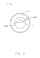
FIG. 2 is a top plan view of the first screw ofFIG. 1 . -
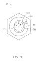
FIG. 3 is a bottom plan view of the second screw ofFIG. 1 . -
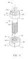
FIG. 4 is an isometric view of a second embodiment of a screw fastener. -
FIG. 5 is a flowchart of a first embodiment of a fastening method. -
FIG. 6 is a flowchart of a second embodiment of a fastening method. -
FIG. 7 is a flowchart of a third embodiment of a fastening method. - It will be appreciated that for simplicity and clarity of illustration, where appropriate, reference numerals have been repeated among the different figures to indicate corresponding or analogous elements. In addition, numerous specific details are set forth in order to provide a thorough understanding of the embodiments described herein. However, it will be understood by those of ordinary skill in the art that the embodiments described herein can be practiced without these specific details. In other instances, methods, procedures, and components have not been described in detail so as not to obscure the related relevant feature being described. Also, the description is not to be considered as limiting the scope of the embodiments described herein. The drawings are not necessarily to scale and the proportions of certain parts have been exaggerated to better illustrate details and features of the present disclosure.
- Several definitions that apply throughout this disclosure will now be presented.
- The term "coupled" is defined as connected, whether directly or indirectly through intervening components, and is not necessarily limited to physical connections. The connection can be such that the objects are permanently connected or releasably connected. The term "substantially" is defined to be essentially conforming to the particular dimension, shape, or other feature that the term modifies, such that the component need not be exact. For example, "substantially cylindrical" means that the object resembles a cylinder, but can have one or more deviations from a true cylinder. The term "comprising" when utilized, means "including, but not necessarily limited to"; it specifically indicates open-ended inclusion or membership in the so-described combination, group, series and the like.
- The present disclosure is described in relation to fasteners, and particularly to a screw fastener and fastening method using the same.
- A screw fastener can include a first screw having a threaded portion, and a second screw having a threaded hole. The first screw can define a first position portion. A center point of the first position portion can be perpendicularly connected to a center axis of the threaded portion to defining a first fictitious line segment. A thread starting point of the threaded portion can be perpendicularly connected to the center axis to defining a second fictitious line segment. The second screw can define a second position portion. A center point of the second position portion can be perpendicularly connected to a center axis of the threaded hole to defining a third fictitious line segment. A thread starting point of the threaded hole can be perpendicularly connected to the center axis to defining a fourth fictitious line segment. When the first screw is coaxial to the second screw and the second fictitious line segment is parallel to the fourth fictitious line segment, the third fictitious line segment can be parallel to the first fictitious line segment.
- A first fastening method can include the following procedures. A robot can be provided. The robot can include a controlling system, a clamping mechanism, and a machine vision system. The lamping mechanism and the machine vision system can be in signal communication with the controlling system. A screw fastener mentioned above can be provided. Two workpieces being to fixed to each other can be provided. Each of the workpiece can define a though hole thereon. The first screw can be inserted through the through holes. The controlling system can control the clamping mechanism to move the second screw to a position adjacent to the first screw after the machine vision system recognize the first position portion and the second position portion. Such that the second position portion can be aligned to the first position portion. The clamping mechanism can rotate the second screw, thereby the second screw threading onto the first screw.
- A second fastening method can include the following procedures. A robot can be provided. The robot can include a controlling system, a clamping mechanism, and a machine vision system. The lamping mechanism and the machine vision system can be in signal communication with the controlling system. A first screw having a first threaded portion and a first position portion can be provided. A center point of the first position portion can be perpendicularly connected to a center axis of the first threaded portion to define a first fictitious line segment. A thread starting point of the first threaded portion can be perpendicularly connected to the center axis to defining a second fictitious line segment. A workpiece having a second threaded portion configured to thread with the first threaded portion, and a second position portion adjacent to the second threaded portion can be provided. A center point of the second position portion can be perpendicularly connected to a center axis of the second threaded portion, to define a fifth fictitious line segment. A thread starting point of the second threaded portion can be perpendicularly connected to the center axis to defining a sixth fictitious line segment. When the second threaded portion is coaxial to the first screw, and the second fictitious line segment is parallel to the sixth fictitious line segment, the first fictitious line segment can be parallel to the fifth fictitious line segment. The controlling system can control the clamping mechanism to move the first screw to a position adjacent to the second threaded portion after the machine vision system recognize the first position portion and the second position portion. Such that the first position portion being aligned to the second position portion. The clamping mechanism can rotate the first screw, thereby the first screw threading into the second threaded portion.
-
FIG. 1 illustrates an embodiment of ascrew fastener 100. A fastening method can be carried out using thescrew fastener 100 cooperating with an external robot (not shown). Thescrew fastener 100 can include afirst screw 10 and asecond screw 30 configured to thread onto thefirst screw 10. The robot can be configured to position thefirst screw 10 to a first workpiece (not shown), and enable thefirst screw 10 to insert through a second workpiece (not shown) stacked on the first workpiece, and move thesecond screw 30 to thread onto thefirst screw 10. Such that the first workpiece can be fixed to the second workpiece. - In the illustrated embodiment, the
first screw 10 can be a six hexagon head bolt. Thefirst screw 10 can include ahead 12 and ashank 14 forming at an end of thehead 12. - The
head 12 can be substantially cylindrical. Thehead 12 can include afirst end surface 121, asecond end surface 123 parallel to thefirst end surface 121 and departing from thefirst end surface 121, and afirst periphery 125 coupled to thefirst end surface 121 and thesecond end surface 123. Thehead 12 can define afirst position portion 1211 on thefirst end surface 121. Thefirst position portion 1211 can be configured to position thesecond screw 30. In the illustrated embodiment, thefirst position portion 1211 can be a sunken portion. - The
shank 14 can protrude from thefirst end surface 121, and can include apolished portion 141 coupled to thehead 12, and a threaded portion 143 coupled to an end of thepolished portion 141. The threaded portion 143 can be configured to couple with thesecond screw 30. - Referring to
FIGS. 1 and2 , a center point of thefirst position portion 1211 can be perpendicularly connected to a center axis of the threaded portion 143 to define a first fictitious line segment a . A thread starting point of the threaded portion 143 can be perpendicularly connected to the center axis of the threaded portion 143 to define a second fictitious line segment b . A first plane (not shown) can be defined by the first fictitious line segment a , and perpendicular to the center axis of the threaded portion 143. In the illustrated embodiment, thefirst end surface 121 can be a flat plane. The first plane and thefirst end surface 121 can be in a superposition. A first projection line b1 can be defined when the second fictitious line segment b is projected to the first plane. The first projection line b1 and the first fictitious line segment a can define a first included angle γ (shown inFIG. 2 ). - Referring to
FIGS. 1 and3 , in the illustrated embodiment, thesecond screw 30 can be a hexagonal nut configured to thread onto thefirst screw 10. Thesecond screw 30 can define a threadedhole 301 configured to engage with the threaded portion 143. Thesecond screw 30 can include athird end surface 31, afourth end surface 33 parallel to thethird end surface 31 and departing from thethird end surface 31, and asecond periphery 35 coupled to thethird end surface 31 and thefourth end surface 33. Thethird end surface 31 can be away from thefirst screw 10. The threadedhole 301 can extend from thethird end surface 31 through thefourth end surface 33. Thesecond screw 30 can define asecond position portion 311 on thethird end surface 31 corresponding to thefirst position portion 1211. Thesecond position portion 311 can be configured to cooperate with thefirst position portion 1211 to position thesecond screw 30 relative to thefirst screw 10. In the illustrated embodiment, thesecond position portion 311 can be a sunken portion. - A center point of the
second position portion 311 can be perpendicularly connected to a center axis of the threadedhole 301 to define a third fictitious line segment c . A thread starting point of the threadedhole 301 can be perpendicularly connected to the center axis of the threadedhole 301 to define a fourth fictitious line segment d. A second plane (not shown) can be defined by the fourth fictitious line segment d, and perpendicular to thecenter axis of the threadedhole 301. In the illustrated embodiment, thethird end surface 31 can be a flat plane. The second plane and thethird end surface 31 can be in a superposition. A second projection line c1 can be defined when the third fictitious line segment c is projected to the second plane. The second projection line c1 and the fourth fictitious line segment d can define a second included angle β (shown inFIG. 3 ). The first included angle γ can be equal to the second included angle β. - A third plane (not shown) can be defined as being perpendicular to the center axis of the threaded
hole 301. When thethread hole 301 is coaxial to the threaded portion 143 and the thread starting point of the threadedhole 301 is aligned to the same of the threaded portion 143, the first included angle γ can be projected to the third plane (not shown) to define a first projection angle (not shown); the second included angle β can be projected to the third plane to define a second projection angle (not shown). The first projection angle and the second projection angle can be in a superposition. - Referring to
FIG. 4 , in an alternative embodiment, the first included angle γ and the second included angle β can be about or more than 0 degrees. When the first included angle γ and the second included angle β are 0 degrees, the first fictitious line segment a can be parallel to the second fictitious line segment b (shown inFIG. 4 ), and the third fictitious line segment c can be parallel to the fourth fictitious line segment d. The fictitious line segment a and the first projection line b1 can be in collineation, the second projection line c1 and the fourth fictitious line segment d can be in collineation. - In an alternative embodiment, the first position portion 1311 can be defined at other location except the
first end surface 121. For example, but not limited to, thefirst position portion 1211 can be defined on thesecond end surface 123 or thefirst periphery 125. Furthermore, thefirst position portion 1211 can be defined on thepolished portion 141 of theshank 14. Such that, when thefirst screw 10 is coaxial to thesecond screw 30, and the second fictitious line segment b is parallel to the fourth fictitious line segment d, the first fictitious line segment a can be parallel to the third fictitious line segment c. In addition, there can be one or morefirst position portions 1211, the one or morefirst position portions 1211 can be defined on at least one of the surfaces as following: thefirst end surface 121, thesecond end surface 123, thefirst periphery 125, and a surface of thepolished portion 141. Similarly, there can be one or moresecond position portions 311, the one or moresecond position portions 311 can be defined on at least one of the surfaces as following: thethird end surface 31, thefourth end surface 33, and thesecond periphery 35. - In an alternative embodiment, the
first position portion 1211 can be in other shapes except a sunken portion. For example, but not limited to, thefirst position portion 1211 can be a protruding portion, a nick, or a planar mark on thefirst screw 10. Furthermore, thefirst position portion 1211 can be a sensor positioned in thefirst screw 10. Such that thefirst position portion 1211 can be recognized by an external machine vision (not shown). Similarly, thesecond position portion 311 can be a protruding portion, a nick, a planar mark, a sensor, or other structure that can be recognized by the external machine vision. - In an alternative embodiment, the
first screw 10 can be other screw fasteners such as, but not limited to, a double-screw bolt or other external screw fasteners. Similarly, thesecond screw 30 can be other screw fasteners such as, but not limited to, a round nut, or other internal screw fasteners, which can be threaded onto thefirst screw 10. -
FIG. 5 illustrates a flowchart in accordance with a first example embodiment. The first example method is provided by way of example, as there are a variety of ways to carry out the method. The method described below can be carried out using the configurations illustrated inFIGS. 1-3 , for example, and various elements of these figures are referenced in explaining example method. Each block shown inFIG. 5 represents one or more processes, methods, or subroutines, carried out in the first example method. Additionally, the illustrated order of blocks is by example only and the order of the blocks can change. The first example method for fastening can be carried out using a screw fastener cooperating with a robot (not shown), in order to fix two workpieces to each other. The first example method for fastening can begin atblock 501. - At
block 501, a robot can be provided. The robot can include a controlling system, a clamping mechanism, and a machine vision system. The lamping mechanism and the machine vision system can be in signal communication with the controlling system. The machine vision system can include an image acquisition module and a visual processing module. The image acquisition module can be configured to acquire a picture of the environment around of. The visual processing module can be configured to analysis the data of the picture to recognize objects in the picture, and deliver and transfer information of the objects to the controlling system. The controlling system can be configured to control the clamping mechanism to work according to the information. - At
block 502, a screw fastener can be provided. The screw fastener can include a first screw and a second screw configured to thread onto the first screw. The first screw can define an external threaded portion and a first position portion thereon. The first position portion can be corresponding to a thread starting point of the threaded portion. The second screw can define a threaded hole and a second position portion thereon. The second position portion can be corresponding to a thread starting point of the threaded hole. - At
block 503, two workpieces can be provided, and will be fixed to each other. Each of the workpieces can define a through hole thereon, and the two through holes can be coaxial to each other. The first screw can be inserted through the through holes. - At
block 504, the controlling system can control the clamping mechanism to catch and hold the second screw after the machine vision system recognize the first position portion and the second position portion. The clamping mechanism can move the second screw to a position adjacent to an end of the first screw. The second screw can be positioned coaxially to the first screw, and the second position portion can be aligned to the first position portion. Such that the thread starting point of the threaded hole can be aligned to the thread starting point of the threaded portion. - At
block 505, the clamping mechanism can rotate the second screw, enabling the second screw to sleeve and thread onto the first screw. -
FIG. 6 illustrates a flowchart in accordance with a second example embodiment. The second example method is provided by way of example, as there are a variety of ways to carry out the method. The method described below can be carried out using the configurations illustrated inFIGS. 1-3 , for example, and various elements of these figures are referenced in explaining example method. Each block shown inFIG. 6 represents one or more processes, methods, or subroutines, carried out in the second example method. Additionally, the illustrated order of blocks is by example only and the order of the blocks can change. The second example method for fastening can be carried out using a first screw cooperating with a robot (not shown), in order to fix a workpiece having an internal threaded hole thereon. The second example method for fastening can begin atblock 601. - At
block 601, a robot can be provided. The robot can include a controlling system, a clamping mechanism, and a machine vision system. The lamping mechanism and the machine vision system can be in signal communication with the controlling system. The machine vision system can include an image acquisition module and a visual processing module. The image acquisition module can be configured to acquire a picture of the environment around of. The visual processing module can be configured to analysis the data of the picture to recognize objects in the picture, and deliver and transfer information of the objects to the controlling system. The controlling system can be configured to control the clamping mechanism to work according to the information. - At
block 602, a first screw can be provided. The first screw can define a threaded portion, and a first position portion adjacent to the threaded portion. A center point of the first position portion can be perpendicularly connected to a center axis of the threaded portion to define a first fictitious line segment. A thread starting point of the threaded portion can be perpendicularly connected to the center axis to define a second fictitious line segment. - At
block 603, a workpiece can be provided. The workpiece can define an internal threaded hole, and a third position portion adjacent to the internal threaded hole. A center point of the third position portion can be perpendicularly connected to a center axis of the threaded hole, to define a fifth fictitious line segment. A thread starting point of the threaded portion can be perpendicularly connected to the center axis to define a sixth fictitious line segment. When the threaded hole on the workpiece is coaxial to the first screw, and the second fictitious line segment is parallel to the sixth fictitious line segment, the first fictitious line segment can be parallel to the fifth fictitious line segment. - At
block 604, the controlling system can control the clamping mechanism to catch and hold the first screw after the machine vision system recognize the first position portion and the third position portion. The clamping mechanism can move the first screw to a position adjacent to the threaded hole on the workpiece. The first screw can be positioned coaxially to the threaded hole, and the first position portion can be aligned to the third position portion, the second fictitious line segment can be parallel to the sixth fictitious line segment. Such that the first fictitious line segment can be parallel to the fifth fictitious line segment, and the thread starting portion of the threaded portion can be aligned to the thread starting portion of the internal threaded hole. - At
block 605, the clamping mechanism can rotate the first screw, enabling the first screw to insert and thread into the threaded hole. -
FIG. 7 illustrates a flowchart in accordance with a third example embodiment. The third example method is provided by way of example, as there are a variety of ways to carry out the method. The method described below can be carried out using the configurations illustrated inFIGS. 1-3 , for example, and various elements of these figures are referenced in explaining example method. Each block shown inFIG. 7 represents one or more processes, methods, or subroutines, carried out in the third example method. Additionally, the illustrated order of blocks is by example only and the order of the blocks can change. The third example method for fastening can be carried out using a second screw cooperating with a robot (not shown), in order to fix a workpiece having an external threaded rod thereon. The third example method for fastening can begin atblock 701. - At
block 701, a robot can be provided. The robot can include a controlling system, a clamping mechanism, and a machine vision system. The lamping mechanism and the machine vision system can be in signal communication with the controlling system. The machine vision system can include an image acquisition module and a visual processing module. The image acquisition module can be configured to acquire a picture of the environment around of. The visual processing module can be configured to analysis the data of the picture to recognize objects in the picture, and deliver and transfer information of the objects to the controlling system. The controlling system can be configured to control the clamping mechanism to work according to the information. - At
block 702, a second screw can be provided. The second screw can define a threaded hole, and a second position portion adjacent to the threaded hole. A center point of the second position portion can be perpendicularly connected to a center axis of the threaded hole, to define a third fictitious line segment. A thread starting point of the threaded hole can be perpendicularly connected to the center axis to define a fourth fictitious line segment. - At
block 703, a workpiece can be provided. The workpiece can include an external threaded rod, and define a fourth position adjacent to the thread rod. A center point of the fourth position portion can be perpendicularly connected to a center axis of the threaded rod, to define a seventh fictitious line segment. A thread starting point of the threaded hole can be perpendicularly connected to the center axis to defining an eighth fictitious line segment. When the threaded rod is coaxial to the second screw, and the fourth fictitious line segment is parallel to the eighth fictitious line segment, the third fictitious line segment can be parallel to the seven fictitious line segment. - At
block 704, the controlling system can control the clamping mechanism to catch and hold the second screw after the machine vision system recognize the second position portion and the fourth position portion. The clamping mechanism can move the second screw to a position adjacent to an end of the threaded rod on the workpiece. The second screw can be positioned coaxially to the threaded rod, and the second position portion can be aligned to the fourth position portion, the fourth fictitious line segment can be parallel to the eighth fictitious line segment. Such that the third fictitious line segment can be parallel to the seventh fictitious line segment, and the thread starting portion of the threaded rod can be aligned to the thread starting portion of the internal threaded hole. - At
block 705, the clamping mechanism can rotate the second screw, enabling the second screw to sleeve and thread onto the threaded rod. - While the present disclosure has been described with reference to particular embodiments, the description is illustrative of the disclosure and is not to be construed as limiting the disclosure. Therefore, those of ordinary skill in the art can make various modifications to the embodiments without departing from the scope of the disclosure, as defined by the appended claims.
Claims (15)
- A screw fastener, comprising:a first screw having a threaded portion; the first screw defining a first position portion, wherein a center point of the first position portion is perpendicularly connected to a center axis of the threaded portion to define a first fictitious line segment, and wherein a thread starting point of the threaded portion is perpendicularly connected to the center axis to define a second fictitious line segment; anda second screw having a threaded hole, the second screw defining a second position portion, wherein a center point of the second position portion is perpendicularly connected to a center axis of the threaded hole to define a third fictitious line segment, and wherein a thread starting point of the threaded hole is perpendicularly connected to the center axis of the threaded hole to define a fourth fictitious line segment;wherein, the first screw and the second screw are configured such that when the first screw is coaxial to the second screw and the second fictitious line segment is parallel to the fourth fictitious line segment, the third fictitious line segment is parallel to the first fictitious line segment.
- The screw fastener of claim 1, wherein an imaginary line of connecting the first position portion and the thread starting point of the threaded portion is coplanar to the center axis of the threaded portion, such that the first fictitious line segment is parallel to the second fictitious line segment; an imaginary line of connecting the second position portion and the thread starting point of the threaded hole is coplanar to the center axis of the threaded hole, such that the third fictitious line segment is parallel to the fourth fictitious line segment.
- The screw fastener of claim 1, wherein the first screw comprises a head and a shank coupled to the head, the threaded portion is positioned on the shank, the first position portion is positioned on the head.
- The screw fastener of claim 3, wherein the head comprises a first end surface, the shank comprises a polished portion coupled to the first end surface, the threaded portion is coupled to an end of the polished portion away from the first end surface, the first position portion is positioned on the first end surface and corresponds to the thread starting point of the threaded portion.
- The screw fastener of claim 1, wherein the second screw comprises a third end surface, a fourth end surface parallel to the third end surface and departing from the third end surface; the threaded hole extends from the third end surface through the fourth end surface.
- The screw fastener of claim 5, wherein the second position portion is positioned on the third end surface and corresponds to the thread starting point of the threaded hole.
- The screw fastener of any of claims 1 to 6, wherein the first screw is a bolt, the second screw is a nut configured to thread with the bolt.
- A fastening method comprising:providing a robot having a controlling system, a clamping mechanism, and a machine vision system; the lamping mechanism and the machine vision system being in signal communication with the controlling system;providing a screw fastener comprising a first screw and a second screw configured to thread with the first screw, wherein the first screw comprises a threaded portion and a first position portion adjacent to the threaded portion; the second screw defines a threaded hole and a second position portion corresponding to the first position portion;providing two workpieces being to fixed to each other, each of the workpiece having a though hole, inserting the first screw through the through holes;moving the second screw to a position adjacent to the first screw via the clamping mechanism controlled by the controlling system after the machine vision system recognize the first position portion and the second position portion; such that the second position portion being aligned to the first position portion; androtating the second screw via the clamping portion, thereby the second screw threading onto the first screw.
- A fastening method comprising:providing a robot having a controlling system, a clamping mechanism, and a machine vision system; the lamping mechanism and the machine vision system being in signal communication with the controlling system;providing a first screw having a first threaded portion, and a first position portion; wherein a center point of the first position portion is perpendicularly connected to a center axis of the first threaded portion to define a first fictitious line segment; a thread starting point of the first threaded portion is perpendicularly connected to the center axis to define a second fictitious line segment;providing a workpiece having a second threaded portion configured to thread with the first threaded portion, and a second position portion adjacent to the second threaded portion; wherein a center point of the second position portion is perpendicularly connected to a center axis of the second threaded portion to define a fifth fictitious line segment; a thread starting point of the second threaded portion is perpendicularly connected to the center axis of the second threaded portion to define a sixth fictitious line segment; when the second threaded portion is coaxial to the first threaded portion on first screw, and the second fictitious line segment is parallel to the sixth fictitious line segment, the first fictitious line segment is parallel to the fifth fictitious line segment.moving the first screw to a position adjacent to the second threaded portion via the clamping mechanism controlled by the controlling system after the machine vision system recognize the first position portion and the second position portion; such that the first position portion being aligned to the second position portion; androtating the first screw via the clamping portion, thereby the first screw threading into the second threaded portion.
- The fastening method of claim 9, wherein machine vision system comprises an image acquisition module configured to acquire a picture of an external environment, and a visual processing module configured to analysis the data of the picture to recognize objects in the picture, and deliver and transfer information of the objects to the controlling system.
- The fastening method of any of claims 9 and claim 10, wherein the first screw is a bolt, the first threaded portion is an external thread forming on the first screw; the second threaded portion is an internal threaded forming on the workpiece.
- The fastening method of any of claims 9 and claim 10, wherein the first screw comprises a head and a shank coupled to the head, the first threaded portion is positioned on the shank, the first position portion is positioned on the head.
- The fastening method of claim 12, wherein the head comprises a first end surface, the shank comprises a polished portion coupled to the first end surface, the first threaded portion is coupled to an end of the polished portion away from the first end surface, the first position portion is positioned on the first end surface and corresponds to the thread starting point of the first threaded portion.
- The fastening method of any of claims 9 and claim 10, wherein the first screw is a nut, the first threaded portion is an internal thread forming on the first screw; the second threaded portion is an external threaded forming on the workpiece.
- The fastening method of claim 14, wherein the first screw comprises a third end surface, a fourth end surface parallel to the third end surface and departing from the third end surface; the first threaded portion extends from the third end surface through the fourth end surface, the first position portion is positioned on the third end surface and corresponds to the thread starting point of the first threaded portion.
Applications Claiming Priority (1)
| Application Number | Priority Date | Filing Date | Title |
|---|---|---|---|
| TW102140011A TWI615555B (en) | 2013-11-04 | 2013-11-04 | Screw fastener and joining method using the same |
Publications (2)
| Publication Number | Publication Date |
|---|---|
| EP2868936A1 true EP2868936A1 (en) | 2015-05-06 |
| EP2868936B1 EP2868936B1 (en) | 2017-05-03 |
Family
ID=52102374
Family Applications (1)
| Application Number | Title | Priority Date | Filing Date |
|---|---|---|---|
| EP14191450.7A Not-in-force EP2868936B1 (en) | 2013-11-04 | 2014-11-03 | Screw fastener and fastening method using the same |
Country Status (5)
| Country | Link |
|---|---|
| US (1) | US20150121681A1 (en) |
| EP (1) | EP2868936B1 (en) |
| JP (1) | JP2015090215A (en) |
| ES (1) | ES2633993T3 (en) |
| TW (1) | TWI615555B (en) |
Families Citing this family (2)
| Publication number | Priority date | Publication date | Assignee | Title |
|---|---|---|---|---|
| CN108112097B (en) * | 2017-12-18 | 2024-07-09 | 开封平煤新型炭材料科技有限公司 | Graphite electrode connection marking positioning method and device |
| USD1023736S1 (en) * | 2022-10-27 | 2024-04-23 | Fleece Performance Engineering, Inc. | Bolt |
Citations (2)
| Publication number | Priority date | Publication date | Assignee | Title |
|---|---|---|---|---|
| US2564029A (en) * | 1947-04-11 | 1951-08-14 | Peterson Dana | Nut and bolt construction |
| EP0625644A1 (en) * | 1993-05-20 | 1994-11-23 | General Electric Company | Positive thread start fastener |
Family Cites Families (8)
| Publication number | Priority date | Publication date | Assignee | Title |
|---|---|---|---|---|
| JPS62167921U (en) * | 1986-04-15 | 1987-10-24 | ||
| JP2000304172A (en) * | 1999-04-16 | 2000-11-02 | Taiheiyo Tokushu Chuzo Kk | Mechanism for resin screw |
| JP3797316B2 (en) * | 2002-09-27 | 2006-07-19 | 株式会社メイドー | Bolts and manufacturing dies |
| JP2006212742A (en) * | 2005-02-04 | 2006-08-17 | National Institute Of Advanced Industrial & Technology | Nut assembly device by task skill |
| TW201008694A (en) * | 2008-08-22 | 2010-03-01 | Evest Corp | Apparatus for assembling screw components |
| JP5582616B2 (en) * | 2009-03-16 | 2014-09-03 | 株式会社青山製作所 | Female thread parts and fastening parts using the same |
| JP5537355B2 (en) * | 2010-09-13 | 2014-07-02 | 株式会社大武ルート工業 | Automatic screw tightening device |
| JP5895347B2 (en) * | 2011-03-01 | 2016-03-30 | セイコーエプソン株式会社 | Robot control apparatus, robot control method, and program |
-
2013
- 2013-11-04 TW TW102140011A patent/TWI615555B/en not_active IP Right Cessation
-
2014
- 2014-10-31 JP JP2014222489A patent/JP2015090215A/en active Pending
- 2014-11-03 EP EP14191450.7A patent/EP2868936B1/en not_active Not-in-force
- 2014-11-03 ES ES14191450.7T patent/ES2633993T3/en active Active
- 2014-11-03 US US14/530,991 patent/US20150121681A1/en not_active Abandoned
Patent Citations (2)
| Publication number | Priority date | Publication date | Assignee | Title |
|---|---|---|---|---|
| US2564029A (en) * | 1947-04-11 | 1951-08-14 | Peterson Dana | Nut and bolt construction |
| EP0625644A1 (en) * | 1993-05-20 | 1994-11-23 | General Electric Company | Positive thread start fastener |
Also Published As
| Publication number | Publication date |
|---|---|
| US20150121681A1 (en) | 2015-05-07 |
| ES2633993T3 (en) | 2017-09-26 |
| TW201518617A (en) | 2015-05-16 |
| JP2015090215A (en) | 2015-05-11 |
| EP2868936B1 (en) | 2017-05-03 |
| TWI615555B (en) | 2018-02-21 |
Similar Documents
| Publication | Publication Date | Title |
|---|---|---|
| CN108312144B (en) | Robot automatic lock payment control system and method based on machine vision | |
| US8301302B2 (en) | Synchronous robotic operation on a structure having a confined space | |
| JP2008264983A (en) | Machine vice for 5-axis control machine tool | |
| US20170266771A1 (en) | Bolting tool and bolt mounting jig | |
| US20150185730A1 (en) | Multi-process automatic machine system | |
| US7963017B2 (en) | Method for tightening a screwed joint on a component in an automated manner, and suitable industrial robot system | |
| CN105931233B (en) | Bolt for transmission line of electricity bolt fastening machine people searches for recognition methods | |
| EP2488328B1 (en) | Arrangement at a vice or a chuck | |
| EP2868936B1 (en) | Screw fastener and fastening method using the same | |
| CN110919562B (en) | Indexing pins, indexing fixtures, and methods of aligning first and second bodies of a structure | |
| US20180297717A1 (en) | Camera assisted robotic system for locating the end of a fastener extending through an aircraft part during manufacture thereof | |
| CN207931162U (en) | A kind of carton vision positioning automatic laminating machine utilizing | |
| CN102773737A (en) | Turning machining method of flange bolt as well as positioning and clamping device for same | |
| TWI661881B (en) | Powder press assembly | |
| CN203843721U (en) | Automobile checking fixture clamp | |
| CN104632853B (en) | Threaded fastener and screwing method thereof | |
| CN204673287U (en) | Base device | |
| Dharmaraj | Automated freeform assembly of threaded fasteners | |
| Liu et al. | Servo control technology for automatic screw-tightening process of robotic arm based on multi-vision sensor | |
| US10994424B2 (en) | Tool exchange device and tool exchange system | |
| CN105904243A (en) | Part fast mounting locking method for numerical control machining | |
| DE102018122927A1 (en) | robot system | |
| CN109093406A (en) | The device that the accurate angle of tool retainer suitable for CNC machine positions and the tool retainer equipped with the device | |
| CN205026367U (en) | Aluminium alloy is with rotating connecting piece | |
| CN206732636U (en) | A kind of novel tooling structure |
Legal Events
| Date | Code | Title | Description |
|---|---|---|---|
| PUAI | Public reference made under article 153(3) epc to a published international application that has entered the european phase |
Free format text: ORIGINAL CODE: 0009012 |
|
| 17P | Request for examination filed |
Effective date: 20141103 |
|
| AK | Designated contracting states |
Kind code of ref document: A1 Designated state(s): AL AT BE BG CH CY CZ DE DK EE ES FI FR GB GR HR HU IE IS IT LI LT LU LV MC MK MT NL NO PL PT RO RS SE SI SK SM TR |
|
| AX | Request for extension of the european patent |
Extension state: BA ME |
|
| R17P | Request for examination filed (corrected) |
Effective date: 20151104 |
|
| RBV | Designated contracting states (corrected) |
Designated state(s): AL AT BE BG CH CY CZ DE DK EE ES FI FR GB GR HR HU IE IS IT LI LT LU LV MC MK MT NL NO PL PT RO RS SE SI SK SM TR |
|
| 17Q | First examination report despatched |
Effective date: 20160224 |
|
| GRAP | Despatch of communication of intention to grant a patent |
Free format text: ORIGINAL CODE: EPIDOSNIGR1 |
|
| STAA | Information on the status of an ep patent application or granted ep patent |
Free format text: STATUS: GRANT OF PATENT IS INTENDED |
|
| INTG | Intention to grant announced |
Effective date: 20170213 |
|
| GRAS | Grant fee paid |
Free format text: ORIGINAL CODE: EPIDOSNIGR3 |
|
| GRAA | (expected) grant |
Free format text: ORIGINAL CODE: 0009210 |
|
| STAA | Information on the status of an ep patent application or granted ep patent |
Free format text: STATUS: THE PATENT HAS BEEN GRANTED |
|
| AK | Designated contracting states |
Kind code of ref document: B1 Designated state(s): AL AT BE BG CH CY CZ DE DK EE ES FI FR GB GR HR HU IE IS IT LI LT LU LV MC MK MT NL NO PL PT RO RS SE SI SK SM TR |
|
| REG | Reference to a national code |
Ref country code: GB Ref legal event code: FG4D |
|
| REG | Reference to a national code |
Ref country code: AT Ref legal event code: REF Ref document number: 890326 Country of ref document: AT Kind code of ref document: T Effective date: 20170515 Ref country code: CH Ref legal event code: EP |
|
| REG | Reference to a national code |
Ref country code: IE Ref legal event code: FG4D |
|
| REG | Reference to a national code |
Ref country code: DE Ref legal event code: R096 Ref document number: 602014009244 Country of ref document: DE |
|
| REG | Reference to a national code |
Ref country code: NL Ref legal event code: FP |
|
| REG | Reference to a national code |
Ref country code: AT Ref legal event code: MK05 Ref document number: 890326 Country of ref document: AT Kind code of ref document: T Effective date: 20170503 |
|
| REG | Reference to a national code |
Ref country code: LT Ref legal event code: MG4D |
|
| REG | Reference to a national code |
Ref country code: ES Ref legal event code: FG2A Ref document number: 2633993 Country of ref document: ES Kind code of ref document: T3 Effective date: 20170926 |
|
| REG | Reference to a national code |
Ref country code: FR Ref legal event code: PLFP Year of fee payment: 4 |
|
| PG25 | Lapsed in a contracting state [announced via postgrant information from national office to epo] |
Ref country code: GR Free format text: LAPSE BECAUSE OF FAILURE TO SUBMIT A TRANSLATION OF THE DESCRIPTION OR TO PAY THE FEE WITHIN THE PRESCRIBED TIME-LIMIT Effective date: 20170804 Ref country code: HR Free format text: LAPSE BECAUSE OF FAILURE TO SUBMIT A TRANSLATION OF THE DESCRIPTION OR TO PAY THE FEE WITHIN THE PRESCRIBED TIME-LIMIT Effective date: 20170503 Ref country code: NO Free format text: LAPSE BECAUSE OF FAILURE TO SUBMIT A TRANSLATION OF THE DESCRIPTION OR TO PAY THE FEE WITHIN THE PRESCRIBED TIME-LIMIT Effective date: 20170803 Ref country code: LT Free format text: LAPSE BECAUSE OF FAILURE TO SUBMIT A TRANSLATION OF THE DESCRIPTION OR TO PAY THE FEE WITHIN THE PRESCRIBED TIME-LIMIT Effective date: 20170503 Ref country code: AT Free format text: LAPSE BECAUSE OF FAILURE TO SUBMIT A TRANSLATION OF THE DESCRIPTION OR TO PAY THE FEE WITHIN THE PRESCRIBED TIME-LIMIT Effective date: 20170503 |
|
| PG25 | Lapsed in a contracting state [announced via postgrant information from national office to epo] |
Ref country code: SE Free format text: LAPSE BECAUSE OF FAILURE TO SUBMIT A TRANSLATION OF THE DESCRIPTION OR TO PAY THE FEE WITHIN THE PRESCRIBED TIME-LIMIT Effective date: 20170503 Ref country code: IS Free format text: LAPSE BECAUSE OF FAILURE TO SUBMIT A TRANSLATION OF THE DESCRIPTION OR TO PAY THE FEE WITHIN THE PRESCRIBED TIME-LIMIT Effective date: 20170903 Ref country code: PL Free format text: LAPSE BECAUSE OF FAILURE TO SUBMIT A TRANSLATION OF THE DESCRIPTION OR TO PAY THE FEE WITHIN THE PRESCRIBED TIME-LIMIT Effective date: 20170503 Ref country code: BG Free format text: LAPSE BECAUSE OF FAILURE TO SUBMIT A TRANSLATION OF THE DESCRIPTION OR TO PAY THE FEE WITHIN THE PRESCRIBED TIME-LIMIT Effective date: 20170803 Ref country code: LV Free format text: LAPSE BECAUSE OF FAILURE TO SUBMIT A TRANSLATION OF THE DESCRIPTION OR TO PAY THE FEE WITHIN THE PRESCRIBED TIME-LIMIT Effective date: 20170503 Ref country code: RS Free format text: LAPSE BECAUSE OF FAILURE TO SUBMIT A TRANSLATION OF THE DESCRIPTION OR TO PAY THE FEE WITHIN THE PRESCRIBED TIME-LIMIT Effective date: 20170503 |
|
| PG25 | Lapsed in a contracting state [announced via postgrant information from national office to epo] |
Ref country code: RO Free format text: LAPSE BECAUSE OF FAILURE TO SUBMIT A TRANSLATION OF THE DESCRIPTION OR TO PAY THE FEE WITHIN THE PRESCRIBED TIME-LIMIT Effective date: 20170503 Ref country code: CZ Free format text: LAPSE BECAUSE OF FAILURE TO SUBMIT A TRANSLATION OF THE DESCRIPTION OR TO PAY THE FEE WITHIN THE PRESCRIBED TIME-LIMIT Effective date: 20170503 Ref country code: DK Free format text: LAPSE BECAUSE OF FAILURE TO SUBMIT A TRANSLATION OF THE DESCRIPTION OR TO PAY THE FEE WITHIN THE PRESCRIBED TIME-LIMIT Effective date: 20170503 Ref country code: EE Free format text: LAPSE BECAUSE OF FAILURE TO SUBMIT A TRANSLATION OF THE DESCRIPTION OR TO PAY THE FEE WITHIN THE PRESCRIBED TIME-LIMIT Effective date: 20170503 Ref country code: SK Free format text: LAPSE BECAUSE OF FAILURE TO SUBMIT A TRANSLATION OF THE DESCRIPTION OR TO PAY THE FEE WITHIN THE PRESCRIBED TIME-LIMIT Effective date: 20170503 |
|
| REG | Reference to a national code |
Ref country code: DE Ref legal event code: R097 Ref document number: 602014009244 Country of ref document: DE |
|
| PG25 | Lapsed in a contracting state [announced via postgrant information from national office to epo] |
Ref country code: SM Free format text: LAPSE BECAUSE OF FAILURE TO SUBMIT A TRANSLATION OF THE DESCRIPTION OR TO PAY THE FEE WITHIN THE PRESCRIBED TIME-LIMIT Effective date: 20170503 |
|
| PLBE | No opposition filed within time limit |
Free format text: ORIGINAL CODE: 0009261 |
|
| STAA | Information on the status of an ep patent application or granted ep patent |
Free format text: STATUS: NO OPPOSITION FILED WITHIN TIME LIMIT |
|
| 26N | No opposition filed |
Effective date: 20180206 |
|
| PG25 | Lapsed in a contracting state [announced via postgrant information from national office to epo] |
Ref country code: SI Free format text: LAPSE BECAUSE OF FAILURE TO SUBMIT A TRANSLATION OF THE DESCRIPTION OR TO PAY THE FEE WITHIN THE PRESCRIBED TIME-LIMIT Effective date: 20170503 |
|
| PG25 | Lapsed in a contracting state [announced via postgrant information from national office to epo] |
Ref country code: MC Free format text: LAPSE BECAUSE OF FAILURE TO SUBMIT A TRANSLATION OF THE DESCRIPTION OR TO PAY THE FEE WITHIN THE PRESCRIBED TIME-LIMIT Effective date: 20170503 |
|
| PG25 | Lapsed in a contracting state [announced via postgrant information from national office to epo] |
Ref country code: CH Free format text: LAPSE BECAUSE OF NON-PAYMENT OF DUE FEES Effective date: 20171130 Ref country code: LI Free format text: LAPSE BECAUSE OF NON-PAYMENT OF DUE FEES Effective date: 20171130 |
|
| PG25 | Lapsed in a contracting state [announced via postgrant information from national office to epo] |
Ref country code: LU Free format text: LAPSE BECAUSE OF NON-PAYMENT OF DUE FEES Effective date: 20171103 |
|
| REG | Reference to a national code |
Ref country code: BE Ref legal event code: MM Effective date: 20171130 |
|
| REG | Reference to a national code |
Ref country code: IE Ref legal event code: MM4A |
|
| PG25 | Lapsed in a contracting state [announced via postgrant information from national office to epo] |
Ref country code: MT Free format text: LAPSE BECAUSE OF NON-PAYMENT OF DUE FEES Effective date: 20171103 |
|
| PG25 | Lapsed in a contracting state [announced via postgrant information from national office to epo] |
Ref country code: IE Free format text: LAPSE BECAUSE OF NON-PAYMENT OF DUE FEES Effective date: 20171103 |
|
| PG25 | Lapsed in a contracting state [announced via postgrant information from national office to epo] |
Ref country code: BE Free format text: LAPSE BECAUSE OF NON-PAYMENT OF DUE FEES Effective date: 20171130 |
|
| PGFP | Annual fee paid to national office [announced via postgrant information from national office to epo] |
Ref country code: DE Payment date: 20181204 Year of fee payment: 5 Ref country code: FI Payment date: 20181130 Year of fee payment: 5 Ref country code: NL Payment date: 20181130 Year of fee payment: 5 |
|
| PGFP | Annual fee paid to national office [announced via postgrant information from national office to epo] |
Ref country code: FR Payment date: 20181130 Year of fee payment: 5 Ref country code: GB Payment date: 20181205 Year of fee payment: 5 Ref country code: IT Payment date: 20181130 Year of fee payment: 5 |
|
| PGFP | Annual fee paid to national office [announced via postgrant information from national office to epo] |
Ref country code: ES Payment date: 20190104 Year of fee payment: 5 |
|
| PG25 | Lapsed in a contracting state [announced via postgrant information from national office to epo] |
Ref country code: HU Free format text: LAPSE BECAUSE OF FAILURE TO SUBMIT A TRANSLATION OF THE DESCRIPTION OR TO PAY THE FEE WITHIN THE PRESCRIBED TIME-LIMIT; INVALID AB INITIO Effective date: 20141103 |
|
| PG25 | Lapsed in a contracting state [announced via postgrant information from national office to epo] |
Ref country code: CY Free format text: LAPSE BECAUSE OF FAILURE TO SUBMIT A TRANSLATION OF THE DESCRIPTION OR TO PAY THE FEE WITHIN THE PRESCRIBED TIME-LIMIT Effective date: 20170503 |
|
| PG25 | Lapsed in a contracting state [announced via postgrant information from national office to epo] |
Ref country code: MK Free format text: LAPSE BECAUSE OF FAILURE TO SUBMIT A TRANSLATION OF THE DESCRIPTION OR TO PAY THE FEE WITHIN THE PRESCRIBED TIME-LIMIT Effective date: 20170503 |
|
| PG25 | Lapsed in a contracting state [announced via postgrant information from national office to epo] |
Ref country code: TR Free format text: LAPSE BECAUSE OF FAILURE TO SUBMIT A TRANSLATION OF THE DESCRIPTION OR TO PAY THE FEE WITHIN THE PRESCRIBED TIME-LIMIT Effective date: 20170503 |
|
| PG25 | Lapsed in a contracting state [announced via postgrant information from national office to epo] |
Ref country code: PT Free format text: LAPSE BECAUSE OF FAILURE TO SUBMIT A TRANSLATION OF THE DESCRIPTION OR TO PAY THE FEE WITHIN THE PRESCRIBED TIME-LIMIT Effective date: 20170503 |
|
| REG | Reference to a national code |
Ref country code: DE Ref legal event code: R119 Ref document number: 602014009244 Country of ref document: DE |
|
| REG | Reference to a national code |
Ref country code: FI Ref legal event code: MAE |
|
| REG | Reference to a national code |
Ref country code: NL Ref legal event code: MM Effective date: 20191201 |
|
| PG25 | Lapsed in a contracting state [announced via postgrant information from national office to epo] |
Ref country code: FI Free format text: LAPSE BECAUSE OF NON-PAYMENT OF DUE FEES Effective date: 20191103 Ref country code: AL Free format text: LAPSE BECAUSE OF FAILURE TO SUBMIT A TRANSLATION OF THE DESCRIPTION OR TO PAY THE FEE WITHIN THE PRESCRIBED TIME-LIMIT Effective date: 20170503 |
|
| GBPC | Gb: european patent ceased through non-payment of renewal fee |
Effective date: 20191103 |
|
| PG25 | Lapsed in a contracting state [announced via postgrant information from national office to epo] |
Ref country code: NL Free format text: LAPSE BECAUSE OF NON-PAYMENT OF DUE FEES Effective date: 20191201 |
|
| PG25 | Lapsed in a contracting state [announced via postgrant information from national office to epo] |
Ref country code: IT Free format text: LAPSE BECAUSE OF NON-PAYMENT OF DUE FEES Effective date: 20191103 Ref country code: GB Free format text: LAPSE BECAUSE OF NON-PAYMENT OF DUE FEES Effective date: 20191103 Ref country code: FR Free format text: LAPSE BECAUSE OF NON-PAYMENT OF DUE FEES Effective date: 20191130 Ref country code: DE Free format text: LAPSE BECAUSE OF NON-PAYMENT OF DUE FEES Effective date: 20200603 |
|
| REG | Reference to a national code |
Ref country code: ES Ref legal event code: FD2A Effective date: 20210414 |
|
| PG25 | Lapsed in a contracting state [announced via postgrant information from national office to epo] |
Ref country code: ES Free format text: LAPSE BECAUSE OF NON-PAYMENT OF DUE FEES Effective date: 20191104 |