EP2868921A1 - Wind turbine and method for evaluating health state of blade thereof - Google Patents
Wind turbine and method for evaluating health state of blade thereof Download PDFInfo
- Publication number
- EP2868921A1 EP2868921A1 EP20140191055 EP14191055A EP2868921A1 EP 2868921 A1 EP2868921 A1 EP 2868921A1 EP 20140191055 EP20140191055 EP 20140191055 EP 14191055 A EP14191055 A EP 14191055A EP 2868921 A1 EP2868921 A1 EP 2868921A1
- Authority
- EP
- European Patent Office
- Prior art keywords
- blade
- signal
- fault
- wind turbine
- signals
- Prior art date
- Legal status (The legal status is an assumption and is not a legal conclusion. Google has not performed a legal analysis and makes no representation as to the accuracy of the status listed.)
- Granted
Links
Images


Classifications
-
- F—MECHANICAL ENGINEERING; LIGHTING; HEATING; WEAPONS; BLASTING
- F03—MACHINES OR ENGINES FOR LIQUIDS; WIND, SPRING, OR WEIGHT MOTORS; PRODUCING MECHANICAL POWER OR A REACTIVE PROPULSIVE THRUST, NOT OTHERWISE PROVIDED FOR
- F03D—WIND MOTORS
- F03D17/00—Monitoring or testing of wind motors, e.g. diagnostics
-
- G—PHYSICS
- G01—MEASURING; TESTING
- G01L—MEASURING FORCE, STRESS, TORQUE, WORK, MECHANICAL POWER, MECHANICAL EFFICIENCY, OR FLUID PRESSURE
- G01L3/00—Measuring torque, work, mechanical power, or mechanical efficiency, in general
- G01L3/02—Rotary-transmission dynamometers
-
- G—PHYSICS
- G01—MEASURING; TESTING
- G01M—TESTING STATIC OR DYNAMIC BALANCE OF MACHINES OR STRUCTURES; TESTING OF STRUCTURES OR APPARATUS, NOT OTHERWISE PROVIDED FOR
- G01M15/00—Testing of engines
- G01M15/14—Testing gas-turbine engines or jet-propulsion engines
-
- G—PHYSICS
- G01—MEASURING; TESTING
- G01P—MEASURING LINEAR OR ANGULAR SPEED, ACCELERATION, DECELERATION, OR SHOCK; INDICATING PRESENCE, ABSENCE, OR DIRECTION, OF MOVEMENT
- G01P3/00—Measuring linear or angular speed; Measuring differences of linear or angular speeds
-
- F—MECHANICAL ENGINEERING; LIGHTING; HEATING; WEAPONS; BLASTING
- F05—INDEXING SCHEMES RELATING TO ENGINES OR PUMPS IN VARIOUS SUBCLASSES OF CLASSES F01-F04
- F05B—INDEXING SCHEME RELATING TO WIND, SPRING, WEIGHT, INERTIA OR LIKE MOTORS, TO MACHINES OR ENGINES FOR LIQUIDS COVERED BY SUBCLASSES F03B, F03D AND F03G
- F05B2270/00—Control
- F05B2270/30—Control parameters, e.g. input parameters
- F05B2270/334—Vibration measurements
-
- F—MECHANICAL ENGINEERING; LIGHTING; HEATING; WEAPONS; BLASTING
- F05—INDEXING SCHEMES RELATING TO ENGINES OR PUMPS IN VARIOUS SUBCLASSES OF CLASSES F01-F04
- F05B—INDEXING SCHEME RELATING TO WIND, SPRING, WEIGHT, INERTIA OR LIKE MOTORS, TO MACHINES OR ENGINES FOR LIQUIDS COVERED BY SUBCLASSES F03B, F03D AND F03G
- F05B2270/00—Control
- F05B2270/80—Devices generating input signals, e.g. transducers, sensors, cameras or strain gauges
-
- F—MECHANICAL ENGINEERING; LIGHTING; HEATING; WEAPONS; BLASTING
- F05—INDEXING SCHEMES RELATING TO ENGINES OR PUMPS IN VARIOUS SUBCLASSES OF CLASSES F01-F04
- F05B—INDEXING SCHEME RELATING TO WIND, SPRING, WEIGHT, INERTIA OR LIKE MOTORS, TO MACHINES OR ENGINES FOR LIQUIDS COVERED BY SUBCLASSES F03B, F03D AND F03G
- F05B2270/00—Control
- F05B2270/80—Devices generating input signals, e.g. transducers, sensors, cameras or strain gauges
- F05B2270/807—Accelerometers
-
- Y—GENERAL TAGGING OF NEW TECHNOLOGICAL DEVELOPMENTS; GENERAL TAGGING OF CROSS-SECTIONAL TECHNOLOGIES SPANNING OVER SEVERAL SECTIONS OF THE IPC; TECHNICAL SUBJECTS COVERED BY FORMER USPC CROSS-REFERENCE ART COLLECTIONS [XRACs] AND DIGESTS
- Y02—TECHNOLOGIES OR APPLICATIONS FOR MITIGATION OR ADAPTATION AGAINST CLIMATE CHANGE
- Y02E—REDUCTION OF GREENHOUSE GAS [GHG] EMISSIONS, RELATED TO ENERGY GENERATION, TRANSMISSION OR DISTRIBUTION
- Y02E10/00—Energy generation through renewable energy sources
- Y02E10/70—Wind energy
- Y02E10/72—Wind turbines with rotation axis in wind direction
Definitions
- the present invention relates generally to a wind turbine, and in particular, to a method for evaluating a health state of a blade thereof.
- a wind turbine (Wind Turbine) is usually configured to convert the wind energy into electric energy.
- the wind turbine usually operates in a remote area and a severe environment, and when the wind turbine is particularly affected by environments such as frost, dust, and gale, the wind turbine is prone to fail, where faults include, for example, blade crack, blade clamping stagnation, blade strain, blade icing, or overloading. Therefore, in order to prolong a life span of the wind turbine, it is necessary to regularly overhaul and maintain the wind turbine to prevent potential faults.
- manual overhaul is high in cost, and on the other hand, fault detection reliability is not high.
- a blade parameter signal of the wind turbine is monitored in real time and a probability that the wind turbine works in a fault state is evaluated, to reduce unnecessary scheduled maintenance, thereby improving reliability and lowering a maintenance cost.
- a blade pitch (blade pitch), a blade deflection (blade deflection), a local blade angle (local blade angle), a blade bending moment (bending moment), a blade rotating speed (blade rotating speed), a yaw (yaw), a rotor speed (rotor speed), and a structural vibration (structural vibration) in real time, and then analyze these parameters to evaluate occurrence of a fault.
- blade pitch blade pitch
- blade deflection blade deflection
- local blade angle local blade angle
- a blade bending moment bending moment
- blade rotating speed blade rotating speed
- yaw yaw
- rotor speed rotor speed
- structural vibration structural vibration
- a wind turbine including:a micro inertial measurement unit, installed on each blade, and configured to sense a plurality of detection parameter signals at corresponding installation positions; and a monitoring system, configured to monitor an operating state of the plurality of blades, and the monitoring system includes: a. a signal processing unit, configured to obtain a processing parameter signal through calculation based on the plurality of detection parameter signals obtained by the micro inertial measurement unit; b. a signal analyzing unit, configured to analyze each analysis parameter signal to obtain a fault estimation signal, where the analysis parameter signal is selected from the plurality of detection parameter signals and the processing parameter signal, and each fault estimation signal is used to estimate whether a corresponding blade works in a fault state; and c. a fault evaluating unit, configured to evaluate, based on a plurality of fault estimation signals, whether a corresponding blade fails or a probability that the corresponding blade fails.
- Another aspect of the present invention provides a method for evaluating a health state of a wind turbine blade.
- the method includes: sensing a plurality of detection parameter signals at corresponding installation positions by using micro inertial measurement units installed on each blade; obtaining a processing parameter signal through calculation based on the plurality of detection parameter signals; analyzing each analysis parameter signal to obtain a fault estimation signal, where the analysis parameter signal is selected from the plurality of detection parameter signals and the processing parameter signal, and each fault estimation signal is used to estimate whether a corresponding blade works in a fault state; and evaluating, based on a plurality of fault estimation signals, whether a corresponding blade fails or a probability that the corresponding blade fails.
- the present invention uses a micro inertial measurement unit to provide a monitoring system with detection parameter signals, and the micro inertial measurement unit may detect multiple types of parameter signals at the same time and obtain multiple types of processing parameter signals through calculation. Therefore, a cost may be saved and complexity of parameter signal detection may be lowered by installing a small number of micro inertial measurement units.
- Both the detection parameter signals and the processing parameter signal may be used as an analysis parameter signal, and each analysis parameter signal may be analyzed to obtain a fault estimation signal, which is used to evaluate whether a corresponding blade fails or a probability that the corresponding blade works in a fault state.
- the monitoring system used in the present invention is simple in structure, and a fault analysis performed for a plurality of analysis parameter signals may improve accuracy of fault state evaluation.
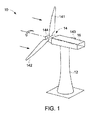
- FIG. 1 is a schematic diagram of a wind turbine 10 according to an implementation manner of the present invention. More specifically, the wind turbine 10 is a horizontal-axis wind turbine.
- the wind turbine 10 includes a tower 12 and a rotor 14.
- the rotor 14 includes several blades, for example, three blades 141, 142, and 143 as shown in FIG. 1 .
- the three blades 141, 142, and 143 are installed on one hub 144.
- the three blades 141, 142, and 143 rotate under thrust of wind energy, and then generate a driving torque to rotate a main axis (not shown) connected to the rotor 14, so as to drive a generator (not shown) to generate electricity through rotation.
- Elements such as the main axis and the generator are installed inside an engine room 16.
- the engine room 16 is installed on the tower 12 in a rotating manner.
- FIG. 1 merely illustrates main components of the wind turbine 10, and in another implementation manner, the wind turbine 10 may also be a wind turbine of another type such as a vertical axis wind turbine.
- FIG. 2 is a schematic diagram of a blade 142 on the wind turbine 10, other blades 141 and 143 also have a similar structure, and only one blade is exemplified for description herein.
- a micro inertial measurement unit (Micro Inertial Measurement Unit, MIMU) 20 is installed on an outer surface of the blade 142.
- the micro inertial measurement unit 20 may also be installed on an inner surface of the blade 142 or embedded in a body of the blade 142.
- micro inertial measurement units 20 may be separately installed on different positions of the blade, such as a tip part, a middle part, a top, and a bottom of the blade, so as to sense enough parameter signals for use of subsequent calculations.
- the words "root part”, “tip part”, “bottom”, “middle part” and “top” herein do not refer to absolute certain points, but may refer to a certain area nearby, and different words are merely used herein for a distinction.
- one micro inertial measurement unit 20 is installed on the middle part of the blade 142 shown in FIG. 2 , and specific installation may be adjusted according to actual requirements.
- the micro inertial measurement unit 20 may be further installed on other parts of the wind turbine 10, for example, installed on the tower 12 or the engine room 16, so as to further provide parameter signals of different positions and types according to requirements.
- the micro inertial measurement unit 20 is a comprehensive motion capture sensing apparatus, and is configured to sense, but not limited to, a three-dimensional direction signal (a pitch angle, a roll angle, and a yaw angle), a three-dimensional accelerated speed signal, a three-dimensional rotating speed signal, a three-dimensional magnetic signal, and so on.
- the micro inertial measurement unit 20 may include a three-dimensional accelerometer, a three-dimensional gyroscope, a three-dimensional magnetometer, or merely include one or two of the foregoing three measuring instruments.
- a cost may be lowered by selecting a micro inertial measurement unit of a suitable type to monitor the several parameters.
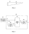
- FIG. 3 is a block diagram of a monitoring system 303 of the wind turbine 10 according to a preferred implementation manner.
- the monitoring system 303 may be installed inside the tower 12 or the engine room 16.
- the monitoring system 303 may be installed in a monitoring room for observation of monitoring personnel.
- the present invention proposes a method for evaluating a probability that the wind turbine works in a fault state based on detection parameter signals of the micro inertial measurement unit.
- the fault state herein includes, but is not limited to, blade crack, blade clamping stagnation, blade strain, blade icing, overloading, and so on.
- the monitoring system 303 is configured to monitor a health state of the blades 141, 142, and 143 according to a plurality of detection parameter signals 311 sensed by the micro inertial measurement unit 20, and more specifically, is configured to monitor whether one or more of the blades 141, 142, and 143 work in a fault state.
- the monitoring system 303 includes a signal processing unit 305, a signal analyzing unit 307, and a fault evaluating unit 309.
- the signal processing unit 305, the signal analyzing unit 307, and the fault evaluating unit 309 may be integrated into a same processing chip.
- the signal processing unit 305, the signal analyzing unit 307, and the fault evaluating unit 309 may belong to different processing chips.
- the signal processing unit 305 is configured to receive the plurality of detection parameter signals 311 sensed by the micro inertial measurement units 20 on the blades 141, 142, and 143, and then obtain one or more specific processing parameter signals 321 by using an embedded algorithm program.
- the signal processing unit 305 may obtain a processing parameter signal 321 through calculation.
- the processing parameter signal 321 may include, but be not limited to, a blade pitch, a blade rotating speed, a structural vibration, a blade deflection, a local blade angle, a blade torque, a blade tip offset, a three-dimensional motion trail, and so on.
- a mathematical model method for calculating the parameter signals of the blade deflection and the local blade angle is given below, where a specific algorithm program may be programmed not only by applying the mathematical model but also by a model method of another type, which is not limited to the implementation manner.
- the elasticity modulus EI(x) of the blade changes over a position x of the blade.
- a total length L of the blade 142 from a root part A 0 to a tip part A n is divided into n parts, where the n parts may be n equal parts with a same length or be n parts with different lengths, and nodes for dividing the n parts successively are A 1 , A 2 ... , and A n-1 . It is assumed that a length from the root part A 0 of the blade 142 to each node A 1 , A 2 ... , A n-1 , and tip part A n is L k (where k ⁇ 1, 2... , n).
- a length from the root part A 0 to the first node A 1 is L 1
- a length from the root part A 0 to the second node A 2 is L 2
- a length from the root part A 0 to the kth node A k is L k .
- An elasticity modulus corresponding to each part is EI k (where k ⁇ 1, 2..., n).
- the blade deflection and the local blade angle which are detected by the micro inertial measurement unit 20 located at the blade 142 and are at an installation position, are received, the blade deflection and the local blade angle at any position on the blade 142 may be obtained through calculation by using the signal processing unit 305.
- a processing parameter signal 321 of another type may be obtained through calculation by using a corresponding algorithm, and descriptions are not made one by one herein.
- the signal analyzing unit 307 may receive at least one signal of the detection parameter signal 311 and the processing parameter signal 321 as an analysis parameter signal. In some implementation manners, it is necessary to select different analysis parameter signals to analyze different fault states of the blade.
- the signal analyzing unit 307 is configured to separately analyze each analysis parameter signal to output respective fault estimation signals 331.
- Each fault estimation signal 331 is used to estimate whether a corresponding blade works in a fault state.
- the fault estimation signal 331 may include a fault value used to estimate that a corresponding blade works in a fault state and a normal value used to estimate that a corresponding blade works in a normal state.
- the fault value may be set to "1", and the normal value may be set to "0".
- the fault value and the normal value may be set to other numerical values.
- a same analysis method is used to analyze different analysis parameter signals.
- different analysis methods are used separately to analyze different analysis parameter signals.
- FIG. 5 is a schematic diagram of the signal analyzing unit 307 shown in FIG. 3 according to an implementation manner.
- the signal analyzing unit 307 includes a first comparer 501, and the first comparer 501 is configured to compare and analyze the analysis parameter signal 511 and a preset parameter signal 512 to generate a fault estimation signal 531.
- the preset parameter signal 512 may come from simulation data based on a simulation model of the blade 142, and more specifically, is high simulation data, which is obtained in a simulated real environment condition and corresponds to the analysis parameter signal 511.
- the preset parameter signal 512 may come from operating data, which is obtained when the blade normally operates and corresponds to the analysis parameter signal 511.
- the operating data may include test data when the blade leaves factory and normally operates and historical data in a real environment after the blade is assembled on the wind turbine 10.
- the historical data may be selected from data corresponding to storage data that a corresponding blade operates in a certain period of time.
- the first comparer 501 is configured to implement a frequency domain comparing method.
- the local blade angle detected by the micro inertial measurement unit 20 installed on the blade 142 is used as the analysis parameter signal 511, and local blade angle data obtained in a simulated same environment based on a blade simulation model is used as the preset parameter signal 512.
- the Fourier Transform (FFT) is performed separately for the local blade angle data 511 measured in real time and the local blade angle data 512 obtained through simulation, to obtain respectively corresponding amplitude-frequency characteristic curves.
- FFT Fourier Transform
- a curve 601 is an amplitude-frequency characteristic curve of the local blade angle data 511 measured in real time
- a curve 602 is an amplitude-frequency characteristic curve of the local blade angle data 512 obtained through simulation.
- an amplitude deviation/amplitude deviation ratio may be used to estimate whether the blade 142 works in a fault state, and an algorithm of the amplitude deviation ratio may be as shown in the following formula: y ⁇ 1 f - y ⁇ 2 f y ⁇ 2 f > y threshold where y 1( f ) is an amplitude function of the amplitude-frequency characteristic curve 601, y 2( f ) is an amplitude function of the amplitude-frequency characteristic curve 602, and y threshold is a set threshold.
- y threshold such as 10%, namely, when the amplitude deviation ratio is too great, the blade 142 is estimated to work in a fault state, and a fault estimation signal 531 generated by the first comparer 501 is the fault value.
- a characteristic frequency point and/or amplitude of the amplitude-frequency characteristic curve of the local blade angle data 511 measured in real time are/is approximately the same as that of the amplitude-frequency characteristic curve of the local blade angle data 512 obtained through simulation, for example, as shown in formula (7)
- a ratio of an absolute value of a difference between y 1( f ) and y ( f ) to y 2( f ) is less than the threshold y threshold , such as 10%, namely, the both are approximately the same
- the blade 142 is estimated to work in a normal state, and a fault estimation signal 531 generated by the first comparer 501 is the normal value.
- a monitor may also be used to directly observe characteristic frequency points of the amplitude-frequency characteristic curve 601 and the amplitude-frequency characteristic curve 602 to estimate whether the blade 142 works in a fault state.
- the characteristic frequency points of the amplitude-frequency characteristic curve 601 are A 0 , A 1 , A 2 , and A 3
- the characteristic frequency points of the amplitude-frequency characteristic curve 602 are B 0 , B 1 , and B 2 . It can be known from the curves that, the characteristic frequency points of the amplitude-frequency characteristics of the amplitude-frequency characteristic curve 601 and the amplitude-frequency characteristic curve 602 are different.
- frequencies and amplitudes of A 0 and B 0 are approximately the same; when A 1 is compared with B 1 , the frequency of A1 is shifted; A 2 has no corresponding frequency point; and when A 3 is compared with B 2 , a frequency band corresponding to B 2 is broader than that of A 3 .
- the characteristic frequency points do not completely correspond to each other, namely, the frequency characteristics are different, the blade 142 is estimated to work in a fault state, and a fault estimation signal 531 generated by the first comparer 501 is the fault value.
- the blade 142 is estimated to work in a normal state, and a fault estimation signal 531 generated by the first comparer 501 is the normal value.
- the foregoing amplitude-frequency characteristic may also be obtained through calculation by using another algorithm, such as the Hilbert Transform algorithm and the Wiener Transform algorithm.
- the first comparer 501 may also compare the analysis parameter signal 511 with the preset parameter signal 512 by using a time domain comparing method, such as a statistical method of a histogram analysis algorithm, a variance analysis algorithm, a power spectrum analysis algorithm, and a parameter model analysis algorithm.
- a time domain comparing method such as a statistical method of a histogram analysis algorithm, a variance analysis algorithm, a power spectrum analysis algorithm, and a parameter model analysis algorithm.
- respective statistical characteristics such as a distribution point probability, may be analyzed and compared, to estimate whether the blade 142 works in a fault state.
- the signal analyzing unit 307 further includes a second comparer 502, where the second comparer 502 is configured to compare same analysis parameter signals 521, 522, and 523 of the plurality of blades 141, 142, and 143 to generate a fault estimation signal 532.
- the second comparer 502 is configured to implement a frequency domain comparing method.
- local blade angles which are detected by the micro inertial measurement units 20 installed on the blades 141, 142, and 143 shown in FIG. 2 and are at the same positions, are respectively used as the analysis parameter signals 521, 522, and 523.
- the Fourier Transform (FFT) is performed separately for the local blade angle data 521, 522, and 523, to obtain respectively corresponding amplitude-frequency characteristic curves. As shown in FIG.
- a curve 701 is an amplitude-frequency characteristic curve of the local blade angle data 521 of the blade 141 measured in real time
- a curve 702 is an amplitude-frequency characteristic curve of the local blade angle data 522 of the blade 142 measured in real time
- a curve 703 is an amplitude-frequency characteristic curve of the local blade angle data 523 of the blade 143 measured in real time.
- the formula shown in Formula (7) may be used to calculate amplitude deviations/amplitude deviation ratios corresponding to every two amplitude-frequency characteristic curves, to estimate whether a blade works in a fault state.
- a ratio of an absolute value of a difference between ya ( f ) and yb ( f ) to ya ( f ) is greater than the threshold y threshold , such as 10%
- a ratio of an absolute value of a difference between ya ( f ) and yc ( f ) to ya ( f ) is less than the threshold y threshold 10%
- a ratio of an absolute value of a difference between yb ( f ) and yc ( f ) to ya ( f ) is greater than the threshold y threshold 10%, namely, when the amplitude-frequency characteristic of the amplitude-frequency characteristic curve 702 is different from those of the amplitude-frequency characteristic curves 701 and 703 and the amplitude-frequency characteristic curves 70
- both amplitude deviation ratios of every two of the foregoing blades are less than 10%, namely, when the amplitude-frequency characteristics of the amplitude-frequency characteristic curves 701, 702, and 703 are approximately the same, the blade 142 is estimated to work in a normal state, and a fault estimation signal 532 generated by the second comparer 502 is the normal value.
- a monitor may also be used to directly observe characteristic frequency points of the amplitude-frequency characteristics of the amplitude-frequency characteristic curves 701, 702, and 703, to estimate that a blade works in a fault state.
- the characteristic frequency points of the amplitude-frequency characteristic curve 701 are A 0 , A 1 , A 2 , and A 3
- characteristic frequency points of the amplitude-frequency characteristic curve 702 are B 0 , B 1 , and B 2
- characteristic frequency points of the amplitude-frequency characteristic curve 703 are C 0 , C 1 , C 2 , and C 3 .
- the characteristic frequency points of the amplitude-frequency characteristics of the amplitude-frequency characteristic curve 701 and the amplitude-frequency characteristic curve 702 are different. More specifically, frequencies and amplitudes of A 0 and B 0 are approximately the same; when A 1 is compared with B 1 , the frequency of A1 is shifted; A 2 has no corresponding frequency point; and when A 3 is compared with B 2 , a frequency band corresponding to B 2 is broader than that of A 3 .
- the characteristic frequency points of the amplitude-frequency characteristics of the amplitude-frequency characteristic curve 701 and the amplitude-frequency characteristic curve 703 are approximately the same.
- frequencies and amplitudes of A 0 and Co, A 1 and C 1 , A 2 and C 2 , and A 3 and C 3 are approximately the same separately.
- the characteristic frequency points of the amplitude-frequency characteristics of the amplitude-frequency characteristic curve 703 and the amplitude-frequency characteristic curve 702 are different. More specifically, frequencies and amplitudes of C 0 and B 0 are approximately the same; when C 1 is compared with B 1 , the frequency of C1 is shifted; C 2 has no corresponding frequency point; and when C 3 is compared with B 2 , a frequency band corresponding to B 2 is broader than that of C 3 .
- a fault estimation signal 532 generated by the second comparer 502 is the fault value.
- a fault estimation signal 532 generated by the second comparer 502 is the normal value.
- the foregoing amplitude-frequency characteristic may also be obtained through calculation by using another algorithm, such as the Hilbert Transform algorithm and the Wiener Transform algorithm.
- the second comparer 502 may implement a time domain comparing method, such as a histogram analysis algorithm, a variance analysis algorithm, a power spectrum analysis algorithm, and a parameter model analysis algorithm.
- a time domain comparing method such as a histogram analysis algorithm, a variance analysis algorithm, a power spectrum analysis algorithm, and a parameter model analysis algorithm.
- blade tip offsets which are obtained by processing of the micro inertial measurement units 20 installed on the blades 141, 142, and 143 shown in FIG. 2 and are at the same positions, are respectively used as the analysis parameter signals 521, 522, and 523.
- the histogram analysis method is used separately for the blade tip offsets 521, 522, and 523 obtained by real-time processing, to obtain a probability statistical characteristic curve of the blade tip offsets in a distance of 0 to 3 meters.
- a curve 801 is a statistical characteristic curve of the blade tip offset 521 of the blade 141 obtained by real-time processing
- a curve 802 is a statistical characteristic curve of the blade tip offset 522 of the blade 142 obtained by real-time processing
- a curve 803 is a statistical characteristic curve of the blade tip offset 523 of the blade 143 obtained by real-time processing.
- an absolute value of a difference of probability values of the statistical characteristic curves may be calculated and compared with a set threshold, to estimate whether a blade works in a fault state.
- the fault evaluating unit 309 evaluates, according to the plurality of fault estimation signals 331 by using a corresponding algorithm, a probability that a corresponding blade works in a fault state.
- the fault evaluating unit 309 evaluates, by using a weighting algorithm based on a plurality of fault estimation signals 331, a probability that a corresponding blade works in a fault state.
- w i is a weighted value corresponding to the ith analysis parameter signal, and w i ⁇ (0, 1).
- the weighted value w i corresponding to the ith analysis parameter signal may be obtained through training by using a training algorithm such as a neural algorithm (Neural Algorithm) or a fuzzy algorithm (Fuzzy Algorithm).
- a training algorithm such as a neural algorithm (Neural Algorithm) or a fuzzy algorithm (Fuzzy Algorithm).
- the weighted value w i corresponding to the ith fault estimation signal may be set based on experience according to evaluation importance of the analysis parameter signal for the fault state. For example, when the blade deflection is used as the ith analysis parameter signal and has a great effect on the evaluation of a blade crack fault state, the weighted value w i may be set to 0.4. When P is greater than a set threshold such as 0.75, a corresponding blade is evaluated to work in a fault state.
- an output signal 341 of the fault evaluating unit 309 is the fault probability signal P.
- the output signal 341 when the blade is evaluated to work in a fault state, the output signal 341 is 1, and when the blade is evaluated to work in a normal state, the output signal 341 is 0.
- the fault evaluating unit 309 may use another algorithm based on the plurality of fault estimation signals. For example, when more than a certain percentage of fault estimation signals are fault values, for example, more than 2/3 fault estimation signals are fault values, a corresponding blade is evaluated to work in a fault state. Otherwise, the corresponding blade is evaluated to work in a normal state.
- the output signal 341 is a scale value of a fault estimation signal of the fault value. In another implementation manner, when the blade is evaluated to work in a fault state, the output signal 341 is 1, and when the blade is evaluated to work in a normal state, the output signal 341 is 0.
- FIG. 9 is a schematic block diagram of a wind turbine blade fault monitoring system 903 according to another implementation manner of the present invention.
- the fault monitoring system 903 further includes a life cycle predictor 350.
- the life cycle predictor 350 is configured to analyze the output signal 341 of the fault evaluating unit 309, to obtain a life cycle warning signal 351 of a monitored blade such as the blade 142.
- the life cycle warning signal 351 may be used to estimate time that the blade 142 can still operate, so as to maintain or replace the blade 142.
- the life cycle predictor 350 may implement an accumulation algorithm. For example, when the output signal 341 is the fault probability signal P, P is accumulated, and when an accumulative result is greater than a set threshold such as 100, the life cycle predictor 350 generates the life cycle warning signal 351, to predict that the life cycle of the blade 142 is coming to an end, and that it is necessary to replace the blade 142.
- the life cycle predictor 350 may implement a statistical method, such as a rainflow cycle counting method (Rainflow Cycle Counting Method).
- a rainflow cycle counting method (Rainflow Cycle Counting Method)
- P the fault probability signal
- statistics collection of the rainflow cycle counting method is performed on P, and when times that P is greater than a set threshold (such as 2/3) are more than a set threshold (such as 100), the life cycle predictor 350 generates the life cycle warning signal 351, to predict that the life cycle of the blade 142 is coming to an end, and that it is necessary to replace the blade 142.
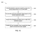
- FIG. 10 is a flowchart of a method 1000 for evaluating a health state of a wind turbine blade according to a preferred implementation manner.
- the method 1000 is used to execute a process shown in FIG. 3 that the monitoring system 303 monitors a blade state.
- the method 1000 includes the following steps. Step 1001: sense a plurality of detection parameter signals 311 at corresponding installation positions by using micro inertial measurement units 20 installed on each blade 141, 142, and 143. Step 1003: calculate based on the plurality of detection parameter signals 311, to obtain a processing parameter signal 321.
- Step 1005 analyze an analysis parameter signal, to obtain a fault estimation signal 331, where the analysis parameter signal is selected from the plurality of detection parameter signals 311 and the processing parameter signal 321, and each fault estimation signal 331 is used to estimate whether a corresponding blade works in a fault state.
- Step 1007 evaluate, based on a plurality of fault estimation signals 331, whether a corresponding blade fails or a probability that the corresponding blade fails.
Landscapes
- Engineering & Computer Science (AREA)
- Physics & Mathematics (AREA)
- General Physics & Mathematics (AREA)
- Chemical & Material Sciences (AREA)
- Combustion & Propulsion (AREA)
- Life Sciences & Earth Sciences (AREA)
- Sustainable Development (AREA)
- Sustainable Energy (AREA)
- Mechanical Engineering (AREA)
- General Engineering & Computer Science (AREA)
- Wind Motors (AREA)
Abstract
Description
- The present invention relates generally to a wind turbine, and in particular, to a method for evaluating a health state of a blade thereof.
- As clean energy, wind energy is widely applied to the power generation field. A wind turbine (Wind Turbine) is usually configured to convert the wind energy into electric energy. However, the wind turbine usually operates in a remote area and a severe environment, and when the wind turbine is particularly affected by environments such as frost, dust, and gale, the wind turbine is prone to fail, where faults include, for example, blade crack, blade clamping stagnation, blade strain, blade icing, or overloading. Therefore, in order to prolong a life span of the wind turbine, it is necessary to regularly overhaul and maintain the wind turbine to prevent potential faults. However, on one hand, manual overhaul is high in cost, and on the other hand, fault detection reliability is not high. A blade parameter signal of the wind turbine is monitored in real time and a probability that the wind turbine works in a fault state is evaluated, to reduce unnecessary scheduled maintenance, thereby improving reliability and lowering a maintenance cost.
- In order to evaluate the fault state of the wind turbine, it is usually necessary to monitor, in a running process of the wind turbine, multiple types of parameters, such as a blade pitch (blade pitch), a blade deflection (blade deflection), a local blade angle (local blade angle), a blade bending moment (bending moment), a blade rotating speed (blade rotating speed), a yaw (yaw), a rotor speed (rotor speed), and a structural vibration (structural vibration) in real time, and then analyze these parameters to evaluate occurrence of a fault. However, because it is necessary to install different types of sensors on each part of the wind turbine at the same time, and sometimes, it is further necessary to install two or more types of sensors on a certain position at the same time, problems such as complicated parameter monitoring and a high cost may be caused. How to use fewest sensors to analyze as many detection parameters as possible to evaluate the probability that the wind turbine works in a fault state becomes a key technical problem to be settled urgently.
- Therefore, it is necessary to provide an improved wind turbine to solve the foregoing technical problem.
- One or more aspects are summarized in the present invention to facilitate a basic understanding of the present invention, where the induction of the present invention do not extend the overview, and is neither intended to identify certain elements of the present invention, nor intended to draw out of its range. On the contrary, the main purpose of the induction is to present some concepts of the present invention in a simplified form before more detailed descriptions are presented below.
- One aspect of the present invention provides a wind turbine, including:a micro inertial measurement unit, installed on each blade, and configured to sense a plurality of detection parameter signals at corresponding installation positions; and a monitoring system, configured to monitor an operating state of the plurality of blades, and the monitoring system includes: a. a signal processing unit, configured to obtain a processing parameter signal through calculation based on the plurality of detection parameter signals obtained by the micro inertial measurement unit; b. a signal analyzing unit, configured to analyze each analysis parameter signal to obtain a fault estimation signal, where the analysis parameter signal is selected from the plurality of detection parameter signals and the processing parameter signal, and each fault estimation signal is used to estimate whether a corresponding blade works in a fault state; and c. a fault evaluating unit, configured to evaluate, based on a plurality of fault estimation signals, whether a corresponding blade fails or a probability that the corresponding blade fails.
- Another aspect of the present invention provides a method for evaluating a health state of a wind turbine blade. The method includes: sensing a plurality of detection parameter signals at corresponding installation positions by using micro inertial measurement units installed on each blade; obtaining a processing parameter signal through calculation based on the plurality of detection parameter signals; analyzing each analysis parameter signal to obtain a fault estimation signal, where the analysis parameter signal is selected from the plurality of detection parameter signals and the processing parameter signal, and each fault estimation signal is used to estimate whether a corresponding blade works in a fault state; and evaluating, based on a plurality of fault estimation signals, whether a corresponding blade fails or a probability that the corresponding blade fails.
- Compared with the prior art, the present invention uses a micro inertial measurement unit to provide a monitoring system with detection parameter signals, and the micro inertial measurement unit may detect multiple types of parameter signals at the same time and obtain multiple types of processing parameter signals through calculation. Therefore, a cost may be saved and complexity of parameter signal detection may be lowered by installing a small number of micro inertial measurement units. Both the detection parameter signals and the processing parameter signal may be used as an analysis parameter signal, and each analysis parameter signal may be analyzed to obtain a fault estimation signal, which is used to evaluate whether a corresponding blade fails or a probability that the corresponding blade works in a fault state. The monitoring system used in the present invention is simple in structure, and a fault analysis performed for a plurality of analysis parameter signals may improve accuracy of fault state evaluation.
- The present invention may be understood in a better way by describing the implementation manners of the present invention with reference to the accompanying drawings, where in the accompanying drawings:
-
FIG. 1 is a schematic diagram of a wind turbine according to an implementation manner of the present invention; -
FIG. 2 is a schematic diagram of a blade on the wind turbine shown inFIG. 1 ; -
FIG. 3 is a schematic block diagram of a wind turbine blade fault monitoring system according to an implementation manner of the present invention; -
FIG. 4 is a schematic diagram of a simplified equivalent cantilever beam model of the blade shown inFIG. 2 ; -
FIG. 5 is a schematic diagram of a signal analyzing unit shown inFIG. 3 according to an implementation manner; -
FIG. 6 is amplitude-frequency characteristic curves of a local blade angle obtained through real-time measurement and a local blade angle obtained through simulation of the blade shown inFIG. 2 ; -
FIG. 7 is amplitude-frequency characteristic curves of local blade angles, which are measured in real time and separately correspond to three blades shown inFIG. 1 ; -
FIG. 8 is statistical characteristic curves of blade tip offsets, which are obtained through processing and separately correspond to three blades shown inFIG. 1 ; -
FIG. 9 is a schematic block diagram of a wind turbine blade fault monitoring system according to another implementation manner of the present invention; and -
FIG. 10 is a flowchart of a method for evaluating a health state of a wind turbine blade according to an implementation manner of the present invention. - The following will describe specific implementation manners of the present invention. It should be noted that, in the specific description process of these implementation manners, in order to make terse and concise descriptions, it is impossible to describe in the specification all features of an actual implementation manner in detail. It should be understood that, in an actual implementation process of any one implementation manner, as in a process of any one project or design project, in order to achieve the developers' specific goals, and in order to meet system-related or business-related limitations, various specific decisions may usually be made, and the decisions may change from one embodiment to another embodiment. In addition, it can also be understood that, although efforts made in the development process may be complicated and lengthy, for a person of ordinary skill in the art related to the content disclosed in the present invention, some changes, such as in design, manufacturing, or production, made based on the technical content disclosed in the disclosure are common technical means, and should be construed that the content of the disclosure is sufficient.
- Unless otherwise defined, the technical terms or scientific terms used in the claims and specification should be the ordinary meaning understood by a person of ordinary skill in the technical field of the present invention. The "first", "second" and similar words used in the patent application specification and claims of the present invention do not denote any order, quantity, or importance, but are just used to distinguish different components. "A" or "an" and other similar words do not denote quantity limitations, but denote that at least one exists. "Comprises" or "comprising" and other similar words imply that an element or object appearing before the "comprises" or "comprising" covers enumerated elements or objects and equivalents elements thereof appearing after the "comprises" or "comprising", without excluding other elements or objects. "Connected" or "coupled" and other similar words are not limited to physical or mechanical connections, but may include electrical connections, either in a direct or indirect manner.
- Referring to
FIG. 1, FIG. 1 is a schematic diagram of awind turbine 10 according to an implementation manner of the present invention. More specifically, thewind turbine 10 is a horizontal-axis wind turbine. Thewind turbine 10 includes atower 12 and arotor 14. Therotor 14 includes several blades, for example, threeblades FIG. 1 . The threeblades hub 144. When working, the threeblades rotor 14, so as to drive a generator (not shown) to generate electricity through rotation. Elements such as the main axis and the generator are installed inside anengine room 16. Theengine room 16 is installed on thetower 12 in a rotating manner. There is a yaw system between thetower 12 and theengine room 16, and the yaw system may adjust a direction of theengine room 16 in real time, so that theblades FIG. 1 merely illustrates main components of thewind turbine 10, and in another implementation manner, thewind turbine 10 may also be a wind turbine of another type such as a vertical axis wind turbine. - Referring to
FIG. 2, FIG. 2 is a schematic diagram of ablade 142 on thewind turbine 10,other blades FIG. 2 , a micro inertial measurement unit (Micro Inertial Measurement Unit, MIMU) 20 is installed on an outer surface of theblade 142. In another implementation manner, the microinertial measurement unit 20 may also be installed on an inner surface of theblade 142 or embedded in a body of theblade 142. Further, there may also be a plurality of the microinertial measurement units 20, which may be separately installed on different positions of the blade, such as a tip part, a middle part, a top, and a bottom of the blade, so as to sense enough parameter signals for use of subsequent calculations. The words "root part", "tip part", "bottom", "middle part" and "top" herein do not refer to absolute certain points, but may refer to a certain area nearby, and different words are merely used herein for a distinction. For example, one microinertial measurement unit 20 is installed on the middle part of theblade 142 shown inFIG. 2 , and specific installation may be adjusted according to actual requirements. In another implementation manner, the microinertial measurement unit 20 may be further installed on other parts of thewind turbine 10, for example, installed on thetower 12 or theengine room 16, so as to further provide parameter signals of different positions and types according to requirements. - It should be noted that, the micro
inertial measurement unit 20 is a comprehensive motion capture sensing apparatus, and is configured to sense, but not limited to, a three-dimensional direction signal (a pitch angle, a roll angle, and a yaw angle), a three-dimensional accelerated speed signal, a three-dimensional rotating speed signal, a three-dimensional magnetic signal, and so on. In a non-limiting implementation manner, the microinertial measurement unit 20 may include a three-dimensional accelerometer, a three-dimensional gyroscope, a three-dimensional magnetometer, or merely include one or two of the foregoing three measuring instruments. In order to evaluate a fault state of thewind turbine 10 especially a fault state of several blades, it is necessary to monitor and analyze several parameters of the blades to determine the fault state of the specific blades. A cost may be lowered by selecting a micro inertial measurement unit of a suitable type to monitor the several parameters. - Referring to
FIG. 3, FIG. 3 is a block diagram of amonitoring system 303 of thewind turbine 10 according to a preferred implementation manner. In some implementation manners, themonitoring system 303 may be installed inside thetower 12 or theengine room 16. In another implementation manner, themonitoring system 303 may be installed in a monitoring room for observation of monitoring personnel. In order to evaluate whether thewind turbine 10 works in a fault state or a probability that thewind turbine 10 works in a fault state, the present invention proposes a method for evaluating a probability that the wind turbine works in a fault state based on detection parameter signals of the micro inertial measurement unit. The fault state herein includes, but is not limited to, blade crack, blade clamping stagnation, blade strain, blade icing, overloading, and so on. - The
monitoring system 303 is configured to monitor a health state of theblades inertial measurement unit 20, and more specifically, is configured to monitor whether one or more of theblades monitoring system 303 includes asignal processing unit 305, asignal analyzing unit 307, and afault evaluating unit 309. In some implementation manners, thesignal processing unit 305, thesignal analyzing unit 307, and thefault evaluating unit 309 may be integrated into a same processing chip. In another implementation manner, thesignal processing unit 305, thesignal analyzing unit 307, and thefault evaluating unit 309 may belong to different processing chips. - The
signal processing unit 305 is configured to receive the plurality of detection parameter signals 311 sensed by the microinertial measurement units 20 on theblades inertial measurement unit 20 on theblade 142 shown inFIG. 2 , thesignal processing unit 305 may obtain aprocessing parameter signal 321 through calculation. Theprocessing parameter signal 321 may include, but be not limited to, a blade pitch, a blade rotating speed, a structural vibration, a blade deflection, a local blade angle, a blade torque, a blade tip offset, a three-dimensional motion trail, and so on. - A mathematical model method for calculating the parameter signals of the blade deflection and the local blade angle is given below, where a specific algorithm program may be programmed not only by applying the mathematical model but also by a model method of another type, which is not limited to the implementation manner.
- The
blade 142 may be simplified to be equivalent to a cantilever beam model shown inFIG. 4 . It is assumed that a mean load borne by the blade is w (N/m), relations between the blade deflection y(x) and a horizontal coordinate x of the cantilever beam and between the local blade angle θ(x) and the horizontal coordinate x of the cantilever beam may be separately represented by using the following formulas:

where EI(x) is an elasticity modulus, and L is a total length of the blade. The elasticity modulus EI(x) of the blade changes over a position x of the blade. As shown inFIG. 4 , a total length L of theblade 142 from a root part A0 to a tip part An is divided into n parts, where the n parts may be n equal parts with a same length or be n parts with different lengths, and nodes for dividing the n parts successively are A1, A2... , and An-1. It is assumed that a length from the root part A0 of theblade 142 to each node A1, A2... , An-1, and tip part An is Lk (where k∈1, 2... , n). For example, a length from the root part A0 to the first node A1 is L1, a length from the root part A0 to the second node A2 is L2, and a length from the root part A0 to the kth node Ak is Lk. An elasticity modulus corresponding to each part is EIk (where k∈1, 2..., n). The blade deflection y(x) and local blade angle θ(x) corresponding to the kth part may be separately represented by using the following formulas:

- A total blade deflection yktotav and a total local blade angle θ ktotal of the kth part of the
blade 142 may be separately represented by using the following formulas:

when the local blade angle and the blade deflection of one part are known, the blade deflection and the local blade angle of any part may be obtained through calculation by using an iterative algorithm. Therefore, after the blade deflection and the local blade angle, which are detected by the microinertial measurement unit 20 located at theblade 142 and are at an installation position, are received, the blade deflection and the local blade angle at any position on theblade 142 may be obtained through calculation by using thesignal processing unit 305. Similarly, aprocessing parameter signal 321 of another type may be obtained through calculation by using a corresponding algorithm, and descriptions are not made one by one herein. - Referring to
FIG. 3 again, thesignal analyzing unit 307 may receive at least one signal of thedetection parameter signal 311 and theprocessing parameter signal 321 as an analysis parameter signal. In some implementation manners, it is necessary to select different analysis parameter signals to analyze different fault states of the blade. Thesignal analyzing unit 307 is configured to separately analyze each analysis parameter signal to output respective fault estimation signals 331. Eachfault estimation signal 331 is used to estimate whether a corresponding blade works in a fault state. In an implementation manner, thefault estimation signal 331 may include a fault value used to estimate that a corresponding blade works in a fault state and a normal value used to estimate that a corresponding blade works in a normal state. In an implementation manner, the fault value may be set to "1", and the normal value may be set to "0". In another implementation manner, the fault value and the normal value may be set to other numerical values. In some implementation manners, a same analysis method is used to analyze different analysis parameter signals. In some implementation manners, different analysis methods are used separately to analyze different analysis parameter signals. - Referring to
FIG. 5, FIG. 5 is a schematic diagram of thesignal analyzing unit 307 shown inFIG. 3 according to an implementation manner. As an example of an analysis method, as shown inFIG. 5 , thesignal analyzing unit 307 includes afirst comparer 501, and thefirst comparer 501 is configured to compare and analyze theanalysis parameter signal 511 and apreset parameter signal 512 to generate afault estimation signal 531. In some implementation manners, thepreset parameter signal 512 may come from simulation data based on a simulation model of theblade 142, and more specifically, is high simulation data, which is obtained in a simulated real environment condition and corresponds to theanalysis parameter signal 511. In some implementation manners, thepreset parameter signal 512 may come from operating data, which is obtained when the blade normally operates and corresponds to theanalysis parameter signal 511. The operating data may include test data when the blade leaves factory and normally operates and historical data in a real environment after the blade is assembled on thewind turbine 10. For example, the historical data may be selected from data corresponding to storage data that a corresponding blade operates in a certain period of time. - More specifically, in an implementation manner, the
first comparer 501 is configured to implement a frequency domain comparing method. As shown inFIG. 2 , the local blade angle detected by the microinertial measurement unit 20 installed on theblade 142 is used as theanalysis parameter signal 511, and local blade angle data obtained in a simulated same environment based on a blade simulation model is used as thepreset parameter signal 512. The Fourier Transform (FFT) is performed separately for the localblade angle data 511 measured in real time and the localblade angle data 512 obtained through simulation, to obtain respectively corresponding amplitude-frequency characteristic curves. As shown inFIG. 6 , acurve 601 is an amplitude-frequency characteristic curve of the localblade angle data 511 measured in real time, and acurve 602 is an amplitude-frequency characteristic curve of the localblade angle data 512 obtained through simulation. In some implementation manners, an amplitude deviation/amplitude deviation ratio may be used to estimate whether theblade 142 works in a fault state, and an algorithm of the amplitude deviation ratio may be as shown in the following formula:
where y1(f) is an amplitude function of the amplitude-frequencycharacteristic curve 601, y2(f) is an amplitude function of the amplitude-frequencycharacteristic curve 602, and ythreshold is a set threshold. For each frequency point f, when a corresponding ratio of an absolute value of a difference between y1(f) and y2(f) to y2(f) is greater than the threshold, ythreshold such as 10%, namely, when the amplitude deviation ratio is too great, theblade 142 is estimated to work in a fault state, and afault estimation signal 531 generated by thefirst comparer 501 is the fault value. - Otherwise, when a characteristic frequency point and/or amplitude of the amplitude-frequency characteristic curve of the local
blade angle data 511 measured in real time are/is approximately the same as that of the amplitude-frequency characteristic curve of the localblade angle data 512 obtained through simulation, for example, as shown in formula (7), when a ratio of an absolute value of a difference between y1(f) and y(f) to y2(f) is less than the threshold ythreshold, such as 10%, namely, the both are approximately the same, theblade 142 is estimated to work in a normal state, and afault estimation signal 531 generated by thefirst comparer 501 is the normal value. - In some implementation manners, a monitor may also be used to directly observe characteristic frequency points of the amplitude-frequency
characteristic curve 601 and the amplitude-frequencycharacteristic curve 602 to estimate whether theblade 142 works in a fault state. The characteristic frequency points of the amplitude-frequencycharacteristic curve 601 are A0, A1, A2, and A3, and the characteristic frequency points of the amplitude-frequencycharacteristic curve 602 are B0, B1, and B2. It can be known from the curves that, the characteristic frequency points of the amplitude-frequency characteristics of the amplitude-frequencycharacteristic curve 601 and the amplitude-frequencycharacteristic curve 602 are different. More specifically, frequencies and amplitudes of A0 and B0 are approximately the same; when A1 is compared with B1, the frequency of A1 is shifted; A2 has no corresponding frequency point; and when A3 is compared with B2, a frequency band corresponding to B2 is broader than that of A3. When the characteristic frequency points do not completely correspond to each other, namely, the frequency characteristics are different, theblade 142 is estimated to work in a fault state, and afault estimation signal 531 generated by thefirst comparer 501 is the fault value. - Otherwise, if all characteristic frequency points of the amplitude-frequency
characteristic curve 601 and the amplitude-frequencycharacteristic curve 602 completely correspond to each other, namely, are approximately the same, theblade 142 is estimated to work in a normal state, and afault estimation signal 531 generated by thefirst comparer 501 is the normal value. Description is made by taking the characteristic frequency point A0 and the characteristic frequency point B0 as an example, if the amplitudes and frequencies of the characteristic frequency point A0 and the characteristic frequency point B0 are the same or a deviation is small, for example, a frequency deviation is merely 1Hz, it may be considered that the characteristic frequency points are approximately the same. - In another implementation manner, the foregoing amplitude-frequency characteristic may also be obtained through calculation by using another algorithm, such as the Hilbert Transform algorithm and the Wiener Transform algorithm.
- In another implementation manner, the
first comparer 501 may also compare theanalysis parameter signal 511 with thepreset parameter signal 512 by using a time domain comparing method, such as a statistical method of a histogram analysis algorithm, a variance analysis algorithm, a power spectrum analysis algorithm, and a parameter model analysis algorithm. In this case, respective statistical characteristics, such as a distribution point probability, may be analyzed and compared, to estimate whether theblade 142 works in a fault state. - As an example of another analysis method, as shown in
FIG. 5 , thesignal analyzing unit 307 further includes asecond comparer 502, where thesecond comparer 502 is configured to compare same analysis parameter signals 521, 522, and 523 of the plurality ofblades fault estimation signal 532. - More specifically, in an implementation manner, the
second comparer 502 is configured to implement a frequency domain comparing method. For example, local blade angles, which are detected by the microinertial measurement units 20 installed on theblades FIG. 2 and are at the same positions, are respectively used as the analysis parameter signals 521, 522, and 523. The Fourier Transform (FFT) is performed separately for the localblade angle data FIG. 7 , acurve 701 is an amplitude-frequency characteristic curve of the localblade angle data 521 of theblade 141 measured in real time, acurve 702 is an amplitude-frequency characteristic curve of the localblade angle data 522 of theblade 142 measured in real time, and acurve 703 is an amplitude-frequency characteristic curve of the localblade angle data 523 of theblade 143 measured in real time. - In some implementation manners, the formula shown in Formula (7) may be used to calculate amplitude deviations/amplitude deviation ratios corresponding to every two amplitude-frequency characteristic curves, to estimate whether a blade works in a fault state. As an example, when a ratio of an absolute value of a difference between ya(f) and yb(f) to ya(f) is greater than the threshold ythreshold, such as 10%, a ratio of an absolute value of a difference between ya(f) and yc(f) to ya(f) is less than the
threshold y threshold 10%, and a ratio of an absolute value of a difference between yb(f) and yc(f) to ya(f) is greater than thethreshold y threshold 10%, namely, when the amplitude-frequency characteristic of the amplitude-frequencycharacteristic curve 702 is different from those of the amplitude-frequencycharacteristic curves characteristic curves blade 142 is estimated to work in a fault state, and afault estimation signal 532 generated by thesecond comparer 502 is the fault value. - Otherwise, if both amplitude deviation ratios of every two of the foregoing blades are less than 10%, namely, when the amplitude-frequency characteristics of the amplitude-frequency
characteristic curves blade 142 is estimated to work in a normal state, and afault estimation signal 532 generated by thesecond comparer 502 is the normal value. - In some implementation manners, a monitor may also be used to directly observe characteristic frequency points of the amplitude-frequency characteristics of the amplitude-frequency
characteristic curves characteristic curve 701 are A0, A1, A2, and A3, characteristic frequency points of the amplitude-frequencycharacteristic curve 702 are B0, B1, and B2, and characteristic frequency points of the amplitude-frequencycharacteristic curve 703 are C0, C1, C2, and C3. It can be known from the curves that, the characteristic frequency points of the amplitude-frequency characteristics of the amplitude-frequencycharacteristic curve 701 and the amplitude-frequencycharacteristic curve 702 are different. More specifically, frequencies and amplitudes of A0 and B0 are approximately the same; when A1 is compared with B1, the frequency of A1 is shifted; A2 has no corresponding frequency point; and when A3 is compared with B2, a frequency band corresponding to B2 is broader than that of A3. The characteristic frequency points of the amplitude-frequency characteristics of the amplitude-frequencycharacteristic curve 701 and the amplitude-frequencycharacteristic curve 703 are approximately the same. More specifically, frequencies and amplitudes of A0 and Co, A1 and C1, A2 and C2, and A3 and C3 are approximately the same separately. The characteristic frequency points of the amplitude-frequency characteristics of the amplitude-frequencycharacteristic curve 703 and the amplitude-frequencycharacteristic curve 702 are different. More specifically, frequencies and amplitudes of C0 and B0 are approximately the same; when C1 is compared with B1, the frequency of C1 is shifted; C2 has no corresponding frequency point; and when C3 is compared with B2, a frequency band corresponding to B2 is broader than that of C3. That is, compared withother blades blade 142 do not completely correspond to each other, theblade 142 is estimated to work in a fault state, and afault estimation signal 532 generated by thesecond comparer 502 is the fault value. - Otherwise, when all characteristic frequency points corresponding to the amplitude-frequency
characteristic curves blades fault estimation signal 532 generated by thesecond comparer 502 is the normal value. Description is made by taking the characteristic frequency point A0, the characteristic frequency point B0 and the characteristic frequency point C0 as an example, if the amplitudes and frequencies of the characteristic frequency point A0, the characteristic frequency point B0, and the characteristic frequency point C0 are the same or a deviation is small, for example, a frequency deviation is merely 1Hz, it may be considered that the characteristic frequency points are approximately the same. - In another implementation manner, the foregoing amplitude-frequency characteristic may also be obtained through calculation by using another algorithm, such as the Hilbert Transform algorithm and the Wiener Transform algorithm.
- In another implementation manner, the
second comparer 502 may implement a time domain comparing method, such as a histogram analysis algorithm, a variance analysis algorithm, a power spectrum analysis algorithm, and a parameter model analysis algorithm. For example, blade tip offsets, which are obtained by processing of the microinertial measurement units 20 installed on theblades FIG. 2 and are at the same positions, are respectively used as the analysis parameter signals 521, 522, and 523. The histogram analysis method is used separately for the blade tip offsets 521, 522, and 523 obtained by real-time processing, to obtain a probability statistical characteristic curve of the blade tip offsets in a distance of 0 to 3 meters. - As shown in
FIG. 8 , acurve 801 is a statistical characteristic curve of the blade tip offset 521 of theblade 141 obtained by real-time processing, acurve 802 is a statistical characteristic curve of the blade tip offset 522 of theblade 142 obtained by real-time processing, and acurve 803 is a statistical characteristic curve of the blade tip offset 523 of theblade 143 obtained by real-time processing. In some implementation manners, an absolute value of a difference of probability values of the statistical characteristic curves may be calculated and compared with a set threshold, to estimate whether a blade works in a fault state. For example, when absolute values of probability differences corresponding to all blade tip offset distance values of the statisticalcharacteristic curve 801 and the statisticalcharacteristic curve 803 are less than aset threshold 1%, a part of or all probability differences at different blade tip offset distance values of the statisticalcharacteristic curve 802 and the statisticalcharacteristic curve 801 are greater than 1%, and a part of or all probability differences at different blade tip offset distance values of the statisticalcharacteristic curve 802 and the statisticalcharacteristic curve 803 are greater than 1%, namely, when statistical characteristics of theblades blade 142 is different from statistical characteristics of theblades blade 142 is estimated to work in a fault state, and afault estimation signal 532 generated by thesecond comparer 502 is the fault value. - Otherwise, when the probability differences corresponding to all blade tip offset distance values of every two statistical characteristic curves among the statistical
characteristic curves blades fault estimation signal 532 generated by thesecond comparer 502 is the normal value. - Return to
FIG. 3 , thefault evaluating unit 309 evaluates, according to the plurality of fault estimation signals 331 by using a corresponding algorithm, a probability that a corresponding blade works in a fault state. - As an example of an algorithm, the
fault evaluating unit 309 evaluates, by using a weighting algorithm based on a plurality of fault estimation signals 331, a probability that a corresponding blade works in a fault state. The weighting algorithm may be represented by using the following formulas:

where P represents a fault probability signal, and Fi is the ith fault estimation signal (fault state: Fi=1; normal state: Fi=0). wi is a weighted value corresponding to the ith analysis parameter signal, and wi ∈ (0, 1). In some implementation manners, the weighted value wi corresponding to the ith analysis parameter signal may be obtained through training by using a training algorithm such as a neural algorithm (Neural Algorithm) or a fuzzy algorithm (Fuzzy Algorithm). In another implementation manner, the weighted value wi corresponding to the ith fault estimation signal may be set based on experience according to evaluation importance of the analysis parameter signal for the fault state. For example, when the blade deflection is used as the ith analysis parameter signal and has a great effect on the evaluation of a blade crack fault state, the weighted value wi may be set to 0.4. When P is greater than a set threshold such as 0.75, a corresponding blade is evaluated to work in a fault state. In some implementation manners, anoutput signal 341 of thefault evaluating unit 309 is the fault probability signal P. In another implementation manner, when the blade is evaluated to work in a fault state, theoutput signal 341 is 1, and when the blade is evaluated to work in a normal state, theoutput signal 341 is 0. - In another implementation manner, the
fault evaluating unit 309 may use another algorithm based on the plurality of fault estimation signals. For example, when more than a certain percentage of fault estimation signals are fault values, for example, more than 2/3 fault estimation signals are fault values, a corresponding blade is evaluated to work in a fault state. Otherwise, the corresponding blade is evaluated to work in a normal state. Similarly, in some implementation manners, theoutput signal 341 is a scale value of a fault estimation signal of the fault value. In another implementation manner, when the blade is evaluated to work in a fault state, theoutput signal 341 is 1, and when the blade is evaluated to work in a normal state, theoutput signal 341 is 0. - Referring to
FIG. 9, FIG. 9 is a schematic block diagram of a wind turbine bladefault monitoring system 903 according to another implementation manner of the present invention. Compared with themonitoring system 303 shown inFIG. 3 , thefault monitoring system 903 further includes alife cycle predictor 350. Thelife cycle predictor 350 is configured to analyze theoutput signal 341 of thefault evaluating unit 309, to obtain a lifecycle warning signal 351 of a monitored blade such as theblade 142. The lifecycle warning signal 351 may be used to estimate time that theblade 142 can still operate, so as to maintain or replace theblade 142. - In an implementation manner, the
life cycle predictor 350 may implement an accumulation algorithm. For example, when theoutput signal 341 is the fault probability signal P, P is accumulated, and when an accumulative result is greater than a set threshold such as 100, thelife cycle predictor 350 generates the lifecycle warning signal 351, to predict that the life cycle of theblade 142 is coming to an end, and that it is necessary to replace theblade 142. - In another implementation manner, the
life cycle predictor 350 may implement a statistical method, such as a rainflow cycle counting method (Rainflow Cycle Counting Method). When theoutput signal 341 is the fault probability signal P, statistics collection of the rainflow cycle counting method is performed on P, and when times that P is greater than a set threshold (such as 2/3) are more than a set threshold (such as 100), thelife cycle predictor 350 generates the lifecycle warning signal 351, to predict that the life cycle of theblade 142 is coming to an end, and that it is necessary to replace theblade 142. - Referring to
FIG. 10, FIG. 10 is a flowchart of amethod 1000 for evaluating a health state of a wind turbine blade according to a preferred implementation manner. Themethod 1000 is used to execute a process shown inFIG. 3 that themonitoring system 303 monitors a blade state. Themethod 1000 includes the following steps. Step 1001: sense a plurality of detection parameter signals 311 at corresponding installation positions by using microinertial measurement units 20 installed on eachblade processing parameter signal 321. Step 1005: analyze an analysis parameter signal, to obtain afault estimation signal 331, where the analysis parameter signal is selected from the plurality of detection parameter signals 311 and theprocessing parameter signal 321, and eachfault estimation signal 331 is used to estimate whether a corresponding blade works in a fault state. Step 1007: evaluate, based on a plurality of fault estimation signals 331, whether a corresponding blade fails or a probability that the corresponding blade fails. A specific working process in the foregoing steps is described in the foregoing paragraphs, and details are not described herein again. - Although the present invention is described with reference to specific implementation manners, a person skilled in the art should understand that, many modifications and variations may be made for the present invention. Therefore, it should be aware that, intention of the claims lies in all the modifications and variations covered in a real concept and scope of the present invention.
Claims (14)
- A wind turbine (10), comprising a plurality of blades (141, 142, 143), wherein the wind turbine (10) further comprises:a micro inertial measurement unit (20), installed on each blade (141, 142, 143), and configured to sense a plurality of detection parameter signals (313) at corresponding installation positions; anda monitoring system (303), configured to monitor an operating state of the plurality of blades (141, 142, 143), and the monitoring system (303) comprises:a signal processing unit (305), configured to obtain a processing parameter signal (321) through calculation based on the plurality of detection parameter signals (313) obtained by the micro inertial measurement unit (20);a signal analyzing unit (304), configured to analyze each analysis parameter signal to obtain a fault estimation signal, wherein the analysis parameter signal is selected from the plurality of detection parameter signals (313) and the processing parameter signal (321), and each fault estimation signal is used to estimate whether a corresponding blade (141, 142, 143) works in a fault state; anda fault evaluating unit (309), configured to evaluate, based on a plurality of fault estimation signals, whether a corresponding blade (141, 142, 143) fails or a probability that the corresponding blade (141, 142, 143) fails.
- The wind turbine (10) according to claim 1, wherein the signal analyzing unit (307) comprises a comparer (501), and the comparer (501) is configured to compare the plurality of analysis parameter signals with a preset parameter signal to generate the fault estimation signal.
- The wind turbine (10) according to claim 2, wherein the comparer (501) is configured to compare and analyze amplitude-frequency characteristics of the analysis parameter signal and the preset parameter signal, and when a deviation between an amplitude-frequency characteristic of the analysis parameter signal and an amplitude-frequency characteristic of the preset parameter signal is greater than a set threshold, estimate that a corresponding blade works in a fault state.
- The wind turbine (10) according to claim 2 or claim 3, wherein the preset parameter signal comes from simulation data, which is based on a blade model and corresponds to the analysis parameter signal, and test data or historical data, which is based on blade operation and corresponds to the analysis parameter signal.
- The wind turbine (10) according to any preceding claim, wherein the signal analyzing unit (304) comprises a comparer (501), and the comparer (501) is configured to compare same analysis parameter signals corresponding to the plurality of blades, and when a deviation between an analysis parameter signal of one blade and an analysis parameter signal of any other blade is greater than a set threshold and all deviations between analysis parameter signals of other blades are less than the set threshold, estimate that the blade works in a fault state.
- The wind turbine (10) according to claim 5, wherein the comparer (501) is configured to compare amplitude-frequency characteristics or statistical characteristics of the same analysis parameter signals corresponding to the plurality of blades.
- The wind turbine (10) according to any preceding claim, wherein the fault evaluating unit (309) evaluates, by using a weighting algorithm based on the plurality of fault estimation signals, the probability that the corresponding blade fails.
- The wind turbine (10) according to any preceding claim, wherein the monitoring system further comprises a life cycle predictor (350), and the life cycle predictor (350) is configured to analyze the fault probability signal to predict a life cycle of a corresponding blade.
- A method (1000) for evaluating a health state of a wind turbine blade (141, 142, 143), comprising:sensing a plurality of detection parameter signals (311, 313) at corresponding installation positions by using micro inertial measurement units (20) installed on each blade (141, 142, 143);
obtaining a processing parameter signal through calculation based on the plurality of detection parameter signals;
analyzing each analysis parameter signal to obtain a fault estimation signal, wherein the analysis parameter signal is selected from the plurality of detection parameter signals and the processing parameter signal, and each fault estimation signal is used to estimate whether a corresponding blade (141, 142, 143) works in a fault state; and
evaluating, based on a plurality of fault estimation signals, whether a corresponding blade (141, 142, 143) fails or a probability that the corresponding blade (141, 142, 143) fails. - The method (1000) according to claim 9, wherein the step of obtaining the fault estimation signal comprises:comparing the plurality of analysis parameter signals (521, 522, 523) with a preset parameter signal; andwhen a deviation between the analysis parameter signal and the preset parameter signal is greater than a set threshold, estimating that the corresponding blade works in a fault state.
- The method (1000) according to claim 10, wherein the comparing step comprises comparing and analyzing amplitude-frequency characteristics of the analysis parameter signal and the preset parameter signal.
- The method (1000) according to any of claims 9 to 11, wherein the comparing step comprises:comparing and analyzing same analysis parameter signals corresponding to the plurality of blades (141, 142, 143); andwhen a deviation between an analysis parameter signal of one blade (141, 142, 143) and an analysis parameter signal of any other blade (141, 142, 143) is greater than a set threshold and all deviations between analysis parameter signals of other blades are less than the set threshold, estimating that the blade works in a fault state.
- The method (1000) according to claim 12, wherein the comparing and analyzing step comprises comparing and analyzing amplitude-frequency characteristics or statistical characteristics of the same analysis parameter signals corresponding to the plurality of blades (141, 142, 143).
- The method (1000) according to any of claims 9 to 13, wherein the step of evaluating the probability that the corresponding blade (141, 142, 143) fails comprises evaluating, by using a weighting algorithm based on the plurality of fault estimation signals, the probability that the corresponding blade (141, 142, 143) fails.
Applications Claiming Priority (1)
| Application Number | Priority Date | Filing Date | Title |
|---|---|---|---|
| CN201310526002.XA CN104595112B (en) | 2013-10-30 | 2013-10-30 | Wind turbine and the method for assessing its blade health status |
Publications (2)
| Publication Number | Publication Date |
|---|---|
| EP2868921A1 true EP2868921A1 (en) | 2015-05-06 |
| EP2868921B1 EP2868921B1 (en) | 2019-02-27 |
Family
ID=51799042
Family Applications (1)
| Application Number | Title | Priority Date | Filing Date |
|---|---|---|---|
| EP14191055.4A Active EP2868921B1 (en) | 2013-10-30 | 2014-10-30 | Wind turbine and method for evaluating health state of blade thereof |
Country Status (4)
| Country | Link |
|---|---|
| US (1) | US10072635B2 (en) |
| EP (1) | EP2868921B1 (en) |
| CN (1) | CN104595112B (en) |
| CA (1) | CA2868643C (en) |
Cited By (1)
| Publication number | Priority date | Publication date | Assignee | Title |
|---|---|---|---|---|
| CN113217299A (en) * | 2021-05-26 | 2021-08-06 | 李晓程 | A control method and system for fault identification and elimination of stuck propellers in wind turbine blades |
Families Citing this family (45)
| Publication number | Priority date | Publication date | Assignee | Title |
|---|---|---|---|---|
| CN105089931A (en) | 2014-05-13 | 2015-11-25 | 通用电气公司 | Draught fan and alignment method for draught fan blades |
| US10156224B2 (en) * | 2015-03-13 | 2018-12-18 | General Electric Company | System and method for controlling a wind turbine |
| EP3317516B1 (en) * | 2015-06-30 | 2021-12-08 | Vestas Wind Systems A/S | Extreme load control |
| US20180163703A1 (en) * | 2015-07-21 | 2018-06-14 | Siemens Aktiengesellschaft | Tower positioning system |
| CN108431404B (en) * | 2015-12-23 | 2020-03-03 | 维斯塔斯风力系统集团公司 | Method and system for controlling multiple wind turbines |
| CN105466670A (en) * | 2015-12-24 | 2016-04-06 | 武汉恒力华振科技有限公司 | Method for health state monitoring of multi-blade collimator based on current signals of blade motor |
| CN107327375B (en) * | 2016-04-28 | 2019-08-02 | 北京天诚同创电气有限公司 | Method and device for determining fan blade parameters |
| KR101764540B1 (en) * | 2016-06-21 | 2017-08-02 | 두산중공업 주식회사 | Vibration Monitoring and Diagnosis System for Wind Turbine |
| US11609114B2 (en) * | 2016-06-27 | 2023-03-21 | University Of Pretoria | Method and system for monitoring rotor blades of a turbomachine using blade tip timing (BTT) |
| JP6805912B2 (en) * | 2017-03-13 | 2020-12-23 | 横河電機株式会社 | Evaluation device, evaluation system, and evaluation method |
| CN107796611B (en) * | 2017-10-20 | 2020-05-15 | 烟台清能风力发电有限公司 | Alarm system for detecting abnormal work of wind driven generator |
| CN109798970B (en) * | 2017-11-17 | 2021-04-02 | 富士电机株式会社 | Abnormality detection device, abnormality detection method, abnormality detection system, and storage medium |
| CN108131247B (en) * | 2017-12-20 | 2020-09-29 | 北京金风科创风电设备有限公司 | Data processing method and device for wind generating set |
| CN108443088B (en) * | 2018-05-17 | 2024-01-16 | 中能电力科技开发有限公司 | Wind turbine generator system state judging method based on cumulative probability distribution |
| CN109472449B (en) * | 2018-10-10 | 2021-09-03 | 同济大学 | Urban rail transit signal equipment health state evaluation method based on group decision |
| CN111400959B (en) * | 2018-12-27 | 2024-01-30 | 北京金风科创风电设备有限公司 | Blade fault diagnosis method and device for wind generating set |
| DE102019207059A1 (en) * | 2019-05-15 | 2020-11-19 | Siemens Aktiengesellschaft | Method for validating system parameters of an energy system, method for operating an energy system and energy management system for an energy system |
| CN112983750B (en) * | 2019-12-13 | 2022-07-19 | 中车株洲电力机车研究所有限公司 | Method and device for diagnosing mounting dislocation of blades of wind turbine generator |
| PL4093967T3 (en) | 2020-01-24 | 2026-03-09 | General Electric Renovables España, S.L. | System and method for controlling a wind turbine |
| JP7285797B2 (en) * | 2020-02-28 | 2023-06-02 | 株式会社東芝 | State evaluation system, state evaluation device, and state evaluation method |
| CN111239249A (en) * | 2020-03-18 | 2020-06-05 | 北京工业大学 | Ventilator blade crack fault diagnosis method based on Hilbert-Huang transform |
| CN113494428B (en) * | 2020-03-20 | 2022-11-22 | 新疆金风科技股份有限公司 | Fault detection method and device of wind generating set |
| CN111412116A (en) * | 2020-04-30 | 2020-07-14 | 河北新天科创新能源技术有限公司 | Failure analysis method for fan variable pitch bearing |
| CN111855383B (en) * | 2020-07-29 | 2023-09-05 | 石河子大学 | A Fatigue Life Prediction Method for Wind Turbine Blades Under Icing Loads |
| EP3954897A1 (en) * | 2020-08-14 | 2022-02-16 | Siemens Gamesa Renewable Energy A/S | Monitoring of blades in wind turbines |
| EP3961031B1 (en) * | 2020-08-25 | 2023-07-12 | Siemens Gamesa Renewable Energy A/S | Monitoring system for a wind turbine blade, wind turbine arrangement and method for monitoring of a wind turbine blade |
| CN114528647A (en) * | 2020-11-23 | 2022-05-24 | 上海电气电站设备有限公司 | Early warning method and evaluation system for water erosion of low-pressure long blade of steam turbine |
| CN114763784B (en) * | 2021-01-12 | 2025-01-10 | 北京国电电力新能源技术有限公司 | Online monitoring and fault warning system for comprehensive health status of fans |
| CN113624334B (en) * | 2021-08-10 | 2023-11-10 | 四川浩淼睿诚科技有限公司 | Unit vibration monitoring device and method based on Internet of things technology |
| CN114166941A (en) * | 2021-11-23 | 2022-03-11 | 哈尔滨工程大学 | Blade crack length parameter online identification method |
| CN114184763A (en) * | 2021-11-23 | 2022-03-15 | 哈尔滨工程大学 | Experimental device and method for online identification of crack positions of turbine blade |
| CN114167026A (en) * | 2021-11-23 | 2022-03-11 | 哈尔滨工程大学 | Experimental device for turbine blade crack quantity online identification |
| CN114135450A (en) * | 2021-12-20 | 2022-03-04 | 博明创能(天津)科技有限公司 | Full life cycle detection method for wind driven generator |
| CN114294183B (en) * | 2021-12-29 | 2025-01-10 | 三一重能股份有限公司 | A method and device for monitoring fan blade faults and a fan |
| CN115077906B (en) * | 2022-06-10 | 2024-11-19 | 潍柴动力股份有限公司 | Method, device, electronic equipment and medium for determining the cause of frequent engine failures |
| JP7847482B2 (en) * | 2022-06-16 | 2026-04-17 | Ntn株式会社 | Control device, terminal device, management system, and management method |
| CN118997978B (en) * | 2023-05-18 | 2026-03-17 | 北京金风科创风电设备有限公司 | A control method, device and equipment for a wind turbine generator set |
| CN116558840B (en) * | 2023-07-12 | 2023-10-13 | 唐智科技湖南发展有限公司 | Method, device, equipment and storage medium for monitoring aero-engine blade |
| CN117028164A (en) * | 2023-07-20 | 2023-11-10 | 灵武市隆桥光伏新能源有限公司 | A wind turbine vibration detection method and equipment |
| CN116857131B (en) * | 2023-07-27 | 2026-01-30 | 西安热工研究院有限公司 | A method, system and equipment for fault diagnosis of wind turbine pitch system |
| CN118424686B (en) * | 2024-05-21 | 2024-11-22 | 长江大学 | Turbine performance testing device and testing method |
| CN118911932B (en) * | 2024-06-27 | 2025-02-11 | 山东金为新能源集团有限公司 | An intelligent inspection and early warning system for faults in new energy wind power generation |
| CN118690181A (en) * | 2024-08-28 | 2024-09-24 | 浙江中自庆安新能源技术有限公司 | An online monitoring method, system and storage medium based on wind turbine soundprint |
| CN119128762B (en) * | 2024-09-12 | 2025-10-24 | 西北工业大学 | Real-time monitoring method of rotor-static friction in high-speed turbine pumps based on RSAF model |
| CN121384874B (en) * | 2025-12-19 | 2026-02-17 | 东北电力大学 | Wind driven generator blade fault detection method based on terahertz analysis |
Citations (4)
| Publication number | Priority date | Publication date | Assignee | Title |
|---|---|---|---|---|
| EP1075600A1 (en) * | 1998-04-30 | 2001-02-14 | Lm Glasfiber A/S | Wind turbine with stress indicator |
| US20120010852A1 (en) * | 2009-03-02 | 2012-01-12 | Suzlon Energy Gmbh | Method for monitoring wind turbines |
| DE102011116961A1 (en) * | 2011-10-26 | 2013-05-02 | Robert Bosch Gmbh | Method for determining a mechanical damage of a rotor blade of a wind power plant |
| WO2013110215A1 (en) * | 2012-01-27 | 2013-08-01 | General Electric Company | Wind turbine and method for determining parameters of wind turbine |
Family Cites Families (12)
| Publication number | Priority date | Publication date | Assignee | Title |
|---|---|---|---|---|
| US7322794B2 (en) | 2003-02-03 | 2008-01-29 | General Electric Company | Method and apparatus for condition-based monitoring of wind turbine components |
| US7822560B2 (en) * | 2004-12-23 | 2010-10-26 | General Electric Company | Methods and apparatuses for wind turbine fatigue load measurement and assessment |
| CN100593641C (en) * | 2008-03-21 | 2010-03-10 | 清华大学 | Inverse system robust control method for variable pitch wind power generation system |
| DE202008005030U1 (en) * | 2008-04-11 | 2008-09-04 | National Penghu University, Makung City | Tester for generator |
| DK2110551T4 (en) | 2008-04-15 | 2019-05-13 | Siemens Ag | Method and device for forecast-based wind turbine control |
| WO2010046403A2 (en) * | 2008-10-23 | 2010-04-29 | Vestas Wind Systems A/S | A wind turbine and a method for monitoring a wind turbine |
| GB2466433B (en) | 2008-12-16 | 2011-05-25 | Vestas Wind Sys As | Turbulence sensor and blade condition sensor system |
| EP2476033B1 (en) | 2009-09-08 | 2019-06-19 | Fraunhofer-Gesellschaft zur Förderung der angewandten Forschung e.V. | Model-based method for monitoring the condition of rotor blades |
| EP2354538A1 (en) | 2010-02-01 | 2011-08-10 | Lm Glasfiber A/S | A method of in situ calibrating load sensors of a wind turbine blade |
| US8463085B2 (en) * | 2010-12-17 | 2013-06-11 | General Electric Company | Systems and methods for monitoring a condition of a rotor blade for a wind turbine |
| US20120209539A1 (en) | 2011-02-10 | 2012-08-16 | Honeywell International Inc. | Turbine fault analysis |
| CN102797634A (en) | 2011-05-27 | 2012-11-28 | 通用电气公司 | Wind turbine and method for monitoring parameter thereof |
-
2013
- 2013-10-30 CN CN201310526002.XA patent/CN104595112B/en active Active
-
2014
- 2014-10-24 CA CA2868643A patent/CA2868643C/en active Active
- 2014-10-30 EP EP14191055.4A patent/EP2868921B1/en active Active
- 2014-10-30 US US14/528,101 patent/US10072635B2/en active Active
Patent Citations (4)
| Publication number | Priority date | Publication date | Assignee | Title |
|---|---|---|---|---|
| EP1075600A1 (en) * | 1998-04-30 | 2001-02-14 | Lm Glasfiber A/S | Wind turbine with stress indicator |
| US20120010852A1 (en) * | 2009-03-02 | 2012-01-12 | Suzlon Energy Gmbh | Method for monitoring wind turbines |
| DE102011116961A1 (en) * | 2011-10-26 | 2013-05-02 | Robert Bosch Gmbh | Method for determining a mechanical damage of a rotor blade of a wind power plant |
| WO2013110215A1 (en) * | 2012-01-27 | 2013-08-01 | General Electric Company | Wind turbine and method for determining parameters of wind turbine |
Non-Patent Citations (1)
| Title |
|---|
| BENT F SORENSEN ET AL: "Fundamentals for Remote Structural Health Monitoring of Wind Turbine Blades ? a Preproject", INTERNET CITATION, 1 May 2002 (2002-05-01), pages 40pp, XP007916730, Retrieved from the Internet <URL:http://130.226.56.153/rispubl/AFM/afmpdf/ris-r-1336.pdf> [retrieved on 20110113] * |
Cited By (1)
| Publication number | Priority date | Publication date | Assignee | Title |
|---|---|---|---|---|
| CN113217299A (en) * | 2021-05-26 | 2021-08-06 | 李晓程 | A control method and system for fault identification and elimination of stuck propellers in wind turbine blades |
Also Published As
| Publication number | Publication date |
|---|---|
| CA2868643A1 (en) | 2015-04-30 |
| CN104595112B (en) | 2018-01-16 |
| EP2868921B1 (en) | 2019-02-27 |
| US10072635B2 (en) | 2018-09-11 |
| CA2868643C (en) | 2021-09-21 |
| CN104595112A (en) | 2015-05-06 |
| US20150134272A1 (en) | 2015-05-14 |
Similar Documents
| Publication | Publication Date | Title |
|---|---|---|
| EP2868921B1 (en) | Wind turbine and method for evaluating health state of blade thereof | |
| US7895018B2 (en) | Event monitoring via combination of signals | |
| Igba et al. | Analysing RMS and peak values of vibration signals for condition monitoring of wind turbine gearboxes | |
| CN107247230B (en) | Rotary motor state monitoring method based on support vector machine and data driving | |
| CN119984799B (en) | Method and system for detecting state of wind power bolt | |
| US9683552B2 (en) | System and method for robust wind turbine operation | |
| US20150322924A1 (en) | Method of monitoring the condition of a wind turbine | |
| JP2018185171A (en) | Fatigue life analysis apparatus for windmill power generator, wind power generation system, and fatigue life analysis method for windmill power generator | |
| JP2015117682A (en) | Wind power generator monitoring system and monitoring method | |
| CN108291527A (en) | A method of monitoring and assessment wind turbine power performance change | |
| CN109416023A (en) | Wind turbine monitoring device, wind turbine monitoring method, wind turbine monitoring program, and storage medium | |
| KR101358397B1 (en) | Fault detection appaturas and method for wind turbin base on acceleration sensor and output power | |
| EP3642481B1 (en) | A method for determining wind turbine blade edgewise load recurrence | |
| CN118607939A (en) | A meteorological source application exploration system and method based on multi-dimensional and multi-data sources | |
| CN119163566B (en) | A wind turbine defect detection method for a wind farm | |
| US11339763B2 (en) | Method for windmill farm monitoring | |
| CN103217645B (en) | The blower fan hidden failure monitoring method of wind energy turbine set | |
| Barahona et al. | Applying design knowledge and machine learning to scada data for classification of wind turbine operating regimes | |
| CN116928039B (en) | Method, device, equipment and medium for identifying vibration overrun faults of offshore wind turbine generator | |
| De Sitter et al. | Monitoring changes in the soil and foundation characteristics of an offshore wind turbine using automated operational modal analysis | |
| WO2016157503A1 (en) | Windmill, windmill fatigue deterioration diagnosis method, and windmill operation control method | |
| CN105512820A (en) | Wind power plant wind energy resource monitoring and unit running state evaluation method | |
| US20240328393A1 (en) | Method and device for monitoring a machine state of a machine system, in particular a wind power plant | |
| CN119593968A (en) | Wind turbine generator blade abnormality detection method and system based on vibration | |
| CN121659259A (en) | Marine wind power equipment inspection method and device, electronic equipment and storage medium |
Legal Events
| Date | Code | Title | Description |
|---|---|---|---|
| PUAI | Public reference made under article 153(3) epc to a published international application that has entered the european phase |
Free format text: ORIGINAL CODE: 0009012 |
|
| 17P | Request for examination filed |
Effective date: 20141030 |
|
| AK | Designated contracting states |
Kind code of ref document: A1 Designated state(s): AL AT BE BG CH CY CZ DE DK EE ES FI FR GB GR HR HU IE IS IT LI LT LU LV MC MK MT NL NO PL PT RO RS SE SI SK SM TR |
|
| AX | Request for extension of the european patent |
Extension state: BA ME |
|
| R17P | Request for examination filed (corrected) |
Effective date: 20151106 |
|
| RBV | Designated contracting states (corrected) |
Designated state(s): AL AT BE BG CH CY CZ DE DK EE ES FI FR GB GR HR HU IE IS IT LI LT LU LV MC MK MT NL NO PL PT RO RS SE SI SK SM TR |
|
| STAA | Information on the status of an ep patent application or granted ep patent |
Free format text: STATUS: EXAMINATION IS IN PROGRESS |
|
| 17Q | First examination report despatched |
Effective date: 20170926 |
|
| REG | Reference to a national code |
Ref country code: DE Ref legal event code: R079 Ref document number: 602014041711 Country of ref document: DE Free format text: PREVIOUS MAIN CLASS: F03D0011000000 Ipc: F03D0017000000 |
|
| GRAP | Despatch of communication of intention to grant a patent |
Free format text: ORIGINAL CODE: EPIDOSNIGR1 |
|
| STAA | Information on the status of an ep patent application or granted ep patent |
Free format text: STATUS: GRANT OF PATENT IS INTENDED |
|
| RIC1 | Information provided on ipc code assigned before grant |
Ipc: F03D 17/00 20160101AFI20180925BHEP |
|
| INTG | Intention to grant announced |
Effective date: 20181017 |
|
| GRAS | Grant fee paid |
Free format text: ORIGINAL CODE: EPIDOSNIGR3 |
|
| GRAA | (expected) grant |
Free format text: ORIGINAL CODE: 0009210 |
|
| STAA | Information on the status of an ep patent application or granted ep patent |
Free format text: STATUS: THE PATENT HAS BEEN GRANTED |
|
| RIC1 | Information provided on ipc code assigned before grant |
Ipc: F03D 17/00 20160101AFI20180925BHEP |
|
| AK | Designated contracting states |
Kind code of ref document: B1 Designated state(s): AL AT BE BG CH CY CZ DE DK EE ES FI FR GB GR HR HU IE IS IT LI LT LU LV MC MK MT NL NO PL PT RO RS SE SI SK SM TR |
|
| REG | Reference to a national code |
Ref country code: GB Ref legal event code: FG4D |
|
| REG | Reference to a national code |
Ref country code: CH Ref legal event code: EP |
|
| REG | Reference to a national code |
Ref country code: AT Ref legal event code: REF Ref document number: 1101737 Country of ref document: AT Kind code of ref document: T Effective date: 20190315 |
|
| REG | Reference to a national code |
Ref country code: IE Ref legal event code: FG4D |
|
| REG | Reference to a national code |
Ref country code: DE Ref legal event code: R096 Ref document number: 602014041711 Country of ref document: DE |
|
| REG | Reference to a national code |
Ref country code: NL Ref legal event code: MP Effective date: 20190227 |
|
| REG | Reference to a national code |
Ref country code: LT Ref legal event code: MG4D |
|
| PG25 | Lapsed in a contracting state [announced via postgrant information from national office to epo] |
Ref country code: PT Free format text: LAPSE BECAUSE OF FAILURE TO SUBMIT A TRANSLATION OF THE DESCRIPTION OR TO PAY THE FEE WITHIN THE PRESCRIBED TIME-LIMIT Effective date: 20190627 Ref country code: LT Free format text: LAPSE BECAUSE OF FAILURE TO SUBMIT A TRANSLATION OF THE DESCRIPTION OR TO PAY THE FEE WITHIN THE PRESCRIBED TIME-LIMIT Effective date: 20190227 Ref country code: NL Free format text: LAPSE BECAUSE OF FAILURE TO SUBMIT A TRANSLATION OF THE DESCRIPTION OR TO PAY THE FEE WITHIN THE PRESCRIBED TIME-LIMIT Effective date: 20190227 Ref country code: NO Free format text: LAPSE BECAUSE OF FAILURE TO SUBMIT A TRANSLATION OF THE DESCRIPTION OR TO PAY THE FEE WITHIN THE PRESCRIBED TIME-LIMIT Effective date: 20190527 Ref country code: SE Free format text: LAPSE BECAUSE OF FAILURE TO SUBMIT A TRANSLATION OF THE DESCRIPTION OR TO PAY THE FEE WITHIN THE PRESCRIBED TIME-LIMIT Effective date: 20190227 Ref country code: FI Free format text: LAPSE BECAUSE OF FAILURE TO SUBMIT A TRANSLATION OF THE DESCRIPTION OR TO PAY THE FEE WITHIN THE PRESCRIBED TIME-LIMIT Effective date: 20190227 |
|
| PG25 | Lapsed in a contracting state [announced via postgrant information from national office to epo] |
Ref country code: GR Free format text: LAPSE BECAUSE OF FAILURE TO SUBMIT A TRANSLATION OF THE DESCRIPTION OR TO PAY THE FEE WITHIN THE PRESCRIBED TIME-LIMIT Effective date: 20190528 Ref country code: BG Free format text: LAPSE BECAUSE OF FAILURE TO SUBMIT A TRANSLATION OF THE DESCRIPTION OR TO PAY THE FEE WITHIN THE PRESCRIBED TIME-LIMIT Effective date: 20190527 Ref country code: HR Free format text: LAPSE BECAUSE OF FAILURE TO SUBMIT A TRANSLATION OF THE DESCRIPTION OR TO PAY THE FEE WITHIN THE PRESCRIBED TIME-LIMIT Effective date: 20190227 Ref country code: RS Free format text: LAPSE BECAUSE OF FAILURE TO SUBMIT A TRANSLATION OF THE DESCRIPTION OR TO PAY THE FEE WITHIN THE PRESCRIBED TIME-LIMIT Effective date: 20190227 Ref country code: IS Free format text: LAPSE BECAUSE OF FAILURE TO SUBMIT A TRANSLATION OF THE DESCRIPTION OR TO PAY THE FEE WITHIN THE PRESCRIBED TIME-LIMIT Effective date: 20190627 Ref country code: LV Free format text: LAPSE BECAUSE OF FAILURE TO SUBMIT A TRANSLATION OF THE DESCRIPTION OR TO PAY THE FEE WITHIN THE PRESCRIBED TIME-LIMIT Effective date: 20190227 |
|
| REG | Reference to a national code |
Ref country code: AT Ref legal event code: MK05 Ref document number: 1101737 Country of ref document: AT Kind code of ref document: T Effective date: 20190227 |
|
| PG25 | Lapsed in a contracting state [announced via postgrant information from national office to epo] |
Ref country code: SK Free format text: LAPSE BECAUSE OF FAILURE TO SUBMIT A TRANSLATION OF THE DESCRIPTION OR TO PAY THE FEE WITHIN THE PRESCRIBED TIME-LIMIT Effective date: 20190227 Ref country code: RO Free format text: LAPSE BECAUSE OF FAILURE TO SUBMIT A TRANSLATION OF THE DESCRIPTION OR TO PAY THE FEE WITHIN THE PRESCRIBED TIME-LIMIT Effective date: 20190227 Ref country code: CZ Free format text: LAPSE BECAUSE OF FAILURE TO SUBMIT A TRANSLATION OF THE DESCRIPTION OR TO PAY THE FEE WITHIN THE PRESCRIBED TIME-LIMIT Effective date: 20190227 Ref country code: AL Free format text: LAPSE BECAUSE OF FAILURE TO SUBMIT A TRANSLATION OF THE DESCRIPTION OR TO PAY THE FEE WITHIN THE PRESCRIBED TIME-LIMIT Effective date: 20190227 Ref country code: ES Free format text: LAPSE BECAUSE OF FAILURE TO SUBMIT A TRANSLATION OF THE DESCRIPTION OR TO PAY THE FEE WITHIN THE PRESCRIBED TIME-LIMIT Effective date: 20190227 Ref country code: EE Free format text: LAPSE BECAUSE OF FAILURE TO SUBMIT A TRANSLATION OF THE DESCRIPTION OR TO PAY THE FEE WITHIN THE PRESCRIBED TIME-LIMIT Effective date: 20190227 Ref country code: DK Free format text: LAPSE BECAUSE OF FAILURE TO SUBMIT A TRANSLATION OF THE DESCRIPTION OR TO PAY THE FEE WITHIN THE PRESCRIBED TIME-LIMIT Effective date: 20190227 Ref country code: IT Free format text: LAPSE BECAUSE OF FAILURE TO SUBMIT A TRANSLATION OF THE DESCRIPTION OR TO PAY THE FEE WITHIN THE PRESCRIBED TIME-LIMIT Effective date: 20190227 |
|
| REG | Reference to a national code |
Ref country code: DE Ref legal event code: R097 Ref document number: 602014041711 Country of ref document: DE |
|
| PG25 | Lapsed in a contracting state [announced via postgrant information from national office to epo] |
Ref country code: SM Free format text: LAPSE BECAUSE OF FAILURE TO SUBMIT A TRANSLATION OF THE DESCRIPTION OR TO PAY THE FEE WITHIN THE PRESCRIBED TIME-LIMIT Effective date: 20190227 Ref country code: PL Free format text: LAPSE BECAUSE OF FAILURE TO SUBMIT A TRANSLATION OF THE DESCRIPTION OR TO PAY THE FEE WITHIN THE PRESCRIBED TIME-LIMIT Effective date: 20190227 |
|
| PG25 | Lapsed in a contracting state [announced via postgrant information from national office to epo] |
Ref country code: AT Free format text: LAPSE BECAUSE OF FAILURE TO SUBMIT A TRANSLATION OF THE DESCRIPTION OR TO PAY THE FEE WITHIN THE PRESCRIBED TIME-LIMIT Effective date: 20190227 |
|
| PLBE | No opposition filed within time limit |
Free format text: ORIGINAL CODE: 0009261 |
|
| STAA | Information on the status of an ep patent application or granted ep patent |
Free format text: STATUS: NO OPPOSITION FILED WITHIN TIME LIMIT |
|
| 26N | No opposition filed |
Effective date: 20191128 |
|
| PG25 | Lapsed in a contracting state [announced via postgrant information from national office to epo] |
Ref country code: SI Free format text: LAPSE BECAUSE OF FAILURE TO SUBMIT A TRANSLATION OF THE DESCRIPTION OR TO PAY THE FEE WITHIN THE PRESCRIBED TIME-LIMIT Effective date: 20190227 |
|
| PG25 | Lapsed in a contracting state [announced via postgrant information from national office to epo] |
Ref country code: TR Free format text: LAPSE BECAUSE OF FAILURE TO SUBMIT A TRANSLATION OF THE DESCRIPTION OR TO PAY THE FEE WITHIN THE PRESCRIBED TIME-LIMIT Effective date: 20190227 |
|
| PG25 | Lapsed in a contracting state [announced via postgrant information from national office to epo] |
Ref country code: MC Free format text: LAPSE BECAUSE OF FAILURE TO SUBMIT A TRANSLATION OF THE DESCRIPTION OR TO PAY THE FEE WITHIN THE PRESCRIBED TIME-LIMIT Effective date: 20190227 |
|
| REG | Reference to a national code |
Ref country code: CH Ref legal event code: PL |
|
| PG25 | Lapsed in a contracting state [announced via postgrant information from national office to epo] |
Ref country code: CH Free format text: LAPSE BECAUSE OF NON-PAYMENT OF DUE FEES Effective date: 20191031 Ref country code: LI Free format text: LAPSE BECAUSE OF NON-PAYMENT OF DUE FEES Effective date: 20191031 Ref country code: LU Free format text: LAPSE BECAUSE OF NON-PAYMENT OF DUE FEES Effective date: 20191030 |
|
| REG | Reference to a national code |
Ref country code: BE Ref legal event code: MM Effective date: 20191031 |
|
| PG25 | Lapsed in a contracting state [announced via postgrant information from national office to epo] |
Ref country code: BE Free format text: LAPSE BECAUSE OF NON-PAYMENT OF DUE FEES Effective date: 20191031 |
|
| GBPC | Gb: european patent ceased through non-payment of renewal fee |
Effective date: 20191030 |
|
| PG25 | Lapsed in a contracting state [announced via postgrant information from national office to epo] |
Ref country code: IE Free format text: LAPSE BECAUSE OF NON-PAYMENT OF DUE FEES Effective date: 20191030 Ref country code: FR Free format text: LAPSE BECAUSE OF NON-PAYMENT OF DUE FEES Effective date: 20191031 Ref country code: GB Free format text: LAPSE BECAUSE OF NON-PAYMENT OF DUE FEES Effective date: 20191030 |
|
| PG25 | Lapsed in a contracting state [announced via postgrant information from national office to epo] |
Ref country code: CY Free format text: LAPSE BECAUSE OF FAILURE TO SUBMIT A TRANSLATION OF THE DESCRIPTION OR TO PAY THE FEE WITHIN THE PRESCRIBED TIME-LIMIT Effective date: 20190227 |
|
| PG25 | Lapsed in a contracting state [announced via postgrant information from national office to epo] |
Ref country code: MT Free format text: LAPSE BECAUSE OF FAILURE TO SUBMIT A TRANSLATION OF THE DESCRIPTION OR TO PAY THE FEE WITHIN THE PRESCRIBED TIME-LIMIT Effective date: 20190227 Ref country code: HU Free format text: LAPSE BECAUSE OF FAILURE TO SUBMIT A TRANSLATION OF THE DESCRIPTION OR TO PAY THE FEE WITHIN THE PRESCRIBED TIME-LIMIT; INVALID AB INITIO Effective date: 20141030 |
|
| PG25 | Lapsed in a contracting state [announced via postgrant information from national office to epo] |
Ref country code: MK Free format text: LAPSE BECAUSE OF FAILURE TO SUBMIT A TRANSLATION OF THE DESCRIPTION OR TO PAY THE FEE WITHIN THE PRESCRIBED TIME-LIMIT Effective date: 20190227 |
|
| P01 | Opt-out of the competence of the unified patent court (upc) registered |
Effective date: 20230530 |
|
| REG | Reference to a national code |
Ref country code: DE Ref legal event code: R081 Ref document number: 602014041711 Country of ref document: DE Owner name: GENERAL ELECTRIC RENOVABLES ESPANA, S.L., ES Free format text: FORMER OWNER: GENERAL ELECTRIC COMPANY, SCHENECTADY, NY, US Ref country code: DE Ref legal event code: R082 Ref document number: 602014041711 Country of ref document: DE Representative=s name: ZIMMERMANN & PARTNER PATENTANWAELTE MBB, DE |
|
| REG | Reference to a national code |
Ref country code: DE Ref legal event code: R082 Ref document number: 602014041711 Country of ref document: DE Representative=s name: ZIMMERMANN & PARTNER PATENTANWAELTE MBB, DE |
|
| PGFP | Annual fee paid to national office [announced via postgrant information from national office to epo] |
Ref country code: DE Payment date: 20250923 Year of fee payment: 12 |