EP2868920A1 - Wind turbine rotor blade and wind turbine generator with same - Google Patents
Wind turbine rotor blade and wind turbine generator with same Download PDFInfo
- Publication number
- EP2868920A1 EP2868920A1 EP20120891280 EP12891280A EP2868920A1 EP 2868920 A1 EP2868920 A1 EP 2868920A1 EP 20120891280 EP20120891280 EP 20120891280 EP 12891280 A EP12891280 A EP 12891280A EP 2868920 A1 EP2868920 A1 EP 2868920A1
- Authority
- EP
- European Patent Office
- Prior art keywords
- covering layer
- wind turbine
- blade
- region
- blade body
- Prior art date
- Legal status (The legal status is an assumption and is not a legal conclusion. Google has not performed a legal analysis and makes no representation as to the accuracy of the status listed.)
- Withdrawn
Links
- 230000003628 erosive effect Effects 0.000 claims abstract description 66
- 239000011248 coating agent Substances 0.000 claims description 32
- 238000000576 coating method Methods 0.000 claims description 32
- 229920005989 resin Polymers 0.000 claims description 30
- 239000011347 resin Substances 0.000 claims description 30
- 239000002245 particle Substances 0.000 claims description 10
- 239000000919 ceramic Substances 0.000 claims description 6
- 229910052751 metal Inorganic materials 0.000 claims description 6
- 239000002184 metal Substances 0.000 claims description 6
- 239000002923 metal particle Substances 0.000 claims description 6
- YCKRFDGAMUMZLT-UHFFFAOYSA-N Fluorine atom Chemical compound [F] YCKRFDGAMUMZLT-UHFFFAOYSA-N 0.000 claims description 5
- 229910052731 fluorine Inorganic materials 0.000 claims description 5
- 239000011737 fluorine Substances 0.000 claims description 5
- 229920005749 polyurethane resin Polymers 0.000 claims description 5
- 229920001567 vinyl ester resin Polymers 0.000 claims description 5
- RYGMFSIKBFXOCR-UHFFFAOYSA-N Copper Chemical compound [Cu] RYGMFSIKBFXOCR-UHFFFAOYSA-N 0.000 claims description 3
- 229910000990 Ni alloy Inorganic materials 0.000 claims description 3
- 229910001069 Ti alloy Inorganic materials 0.000 claims description 3
- 229910052802 copper Inorganic materials 0.000 claims description 3
- 239000010949 copper Substances 0.000 claims description 3
- 150000002739 metals Chemical class 0.000 claims description 3
- 239000010935 stainless steel Substances 0.000 claims description 3
- 229910001220 stainless steel Inorganic materials 0.000 claims description 3
- 239000010410 layer Substances 0.000 description 101
- 238000011534 incubation Methods 0.000 description 17
- 238000012360 testing method Methods 0.000 description 15
- 239000007788 liquid Substances 0.000 description 13
- 239000000463 material Substances 0.000 description 10
- 238000012423 maintenance Methods 0.000 description 9
- 238000004519 manufacturing process Methods 0.000 description 8
- 239000000203 mixture Substances 0.000 description 8
- 238000001556 precipitation Methods 0.000 description 4
- 239000011247 coating layer Substances 0.000 description 3
- 230000004580 weight loss Effects 0.000 description 3
- 230000001360 synchronised effect Effects 0.000 description 2
- 238000010998 test method Methods 0.000 description 2
- 230000005540 biological transmission Effects 0.000 description 1
- 230000003247 decreasing effect Effects 0.000 description 1
- 230000000694 effects Effects 0.000 description 1
- 230000007613 environmental effect Effects 0.000 description 1
- 230000006698 induction Effects 0.000 description 1
- 238000000034 method Methods 0.000 description 1
- 230000004048 modification Effects 0.000 description 1
- 238000012986 modification Methods 0.000 description 1
- 230000002250 progressing effect Effects 0.000 description 1
- 230000007704 transition Effects 0.000 description 1
- 238000011144 upstream manufacturing Methods 0.000 description 1
- 239000013585 weight reducing agent Substances 0.000 description 1
Images




Classifications
-
- F—MECHANICAL ENGINEERING; LIGHTING; HEATING; WEAPONS; BLASTING
- F03—MACHINES OR ENGINES FOR LIQUIDS; WIND, SPRING, OR WEIGHT MOTORS; PRODUCING MECHANICAL POWER OR A REACTIVE PROPULSIVE THRUST, NOT OTHERWISE PROVIDED FOR
- F03D—WIND MOTORS
- F03D1/00—Wind motors with rotation axis substantially parallel to the air flow entering the rotor
- F03D1/06—Rotors
- F03D1/065—Rotors characterised by their construction elements
- F03D1/0675—Rotors characterised by their construction elements of the blades
-
- F—MECHANICAL ENGINEERING; LIGHTING; HEATING; WEAPONS; BLASTING
- F05—INDEXING SCHEMES RELATING TO ENGINES OR PUMPS IN VARIOUS SUBCLASSES OF CLASSES F01-F04
- F05B—INDEXING SCHEME RELATING TO WIND, SPRING, WEIGHT, INERTIA OR LIKE MOTORS, TO MACHINES OR ENGINES FOR LIQUIDS COVERED BY SUBCLASSES F03B, F03D AND F03G
- F05B2230/00—Manufacture
- F05B2230/90—Coating; Surface treatment
-
- F—MECHANICAL ENGINEERING; LIGHTING; HEATING; WEAPONS; BLASTING
- F05—INDEXING SCHEMES RELATING TO ENGINES OR PUMPS IN VARIOUS SUBCLASSES OF CLASSES F01-F04
- F05B—INDEXING SCHEME RELATING TO WIND, SPRING, WEIGHT, INERTIA OR LIKE MOTORS, TO MACHINES OR ENGINES FOR LIQUIDS COVERED BY SUBCLASSES F03B, F03D AND F03G
- F05B2280/00—Materials; Properties thereof
- F05B2280/10—Inorganic materials, e.g. metals
- F05B2280/105—Copper
-
- F—MECHANICAL ENGINEERING; LIGHTING; HEATING; WEAPONS; BLASTING
- F05—INDEXING SCHEMES RELATING TO ENGINES OR PUMPS IN VARIOUS SUBCLASSES OF CLASSES F01-F04
- F05B—INDEXING SCHEME RELATING TO WIND, SPRING, WEIGHT, INERTIA OR LIKE MOTORS, TO MACHINES OR ENGINES FOR LIQUIDS COVERED BY SUBCLASSES F03B, F03D AND F03G
- F05B2280/00—Materials; Properties thereof
- F05B2280/10—Inorganic materials, e.g. metals
- F05B2280/107—Alloys
- F05B2280/1071—Steel alloys
-
- F—MECHANICAL ENGINEERING; LIGHTING; HEATING; WEAPONS; BLASTING
- F05—INDEXING SCHEMES RELATING TO ENGINES OR PUMPS IN VARIOUS SUBCLASSES OF CLASSES F01-F04
- F05B—INDEXING SCHEME RELATING TO WIND, SPRING, WEIGHT, INERTIA OR LIKE MOTORS, TO MACHINES OR ENGINES FOR LIQUIDS COVERED BY SUBCLASSES F03B, F03D AND F03G
- F05B2280/00—Materials; Properties thereof
- F05B2280/10—Inorganic materials, e.g. metals
- F05B2280/1074—Alloys not otherwise provided for
-
- F—MECHANICAL ENGINEERING; LIGHTING; HEATING; WEAPONS; BLASTING
- F05—INDEXING SCHEMES RELATING TO ENGINES OR PUMPS IN VARIOUS SUBCLASSES OF CLASSES F01-F04
- F05B—INDEXING SCHEME RELATING TO WIND, SPRING, WEIGHT, INERTIA OR LIKE MOTORS, TO MACHINES OR ENGINES FOR LIQUIDS COVERED BY SUBCLASSES F03B, F03D AND F03G
- F05B2280/00—Materials; Properties thereof
- F05B2280/50—Intrinsic material properties or characteristics
- F05B2280/5007—Hardness
-
- F—MECHANICAL ENGINEERING; LIGHTING; HEATING; WEAPONS; BLASTING
- F05—INDEXING SCHEMES RELATING TO ENGINES OR PUMPS IN VARIOUS SUBCLASSES OF CLASSES F01-F04
- F05B—INDEXING SCHEME RELATING TO WIND, SPRING, WEIGHT, INERTIA OR LIKE MOTORS, TO MACHINES OR ENGINES FOR LIQUIDS COVERED BY SUBCLASSES F03B, F03D AND F03G
- F05B2280/00—Materials; Properties thereof
- F05B2280/60—Properties or characteristics given to material by treatment or manufacturing
- F05B2280/6011—Coating
-
- F—MECHANICAL ENGINEERING; LIGHTING; HEATING; WEAPONS; BLASTING
- F05—INDEXING SCHEMES RELATING TO ENGINES OR PUMPS IN VARIOUS SUBCLASSES OF CLASSES F01-F04
- F05B—INDEXING SCHEME RELATING TO WIND, SPRING, WEIGHT, INERTIA OR LIKE MOTORS, TO MACHINES OR ENGINES FOR LIQUIDS COVERED BY SUBCLASSES F03B, F03D AND F03G
- F05B2280/00—Materials; Properties thereof
- F05B2280/60—Properties or characteristics given to material by treatment or manufacturing
- F05B2280/6015—Resin
-
- Y—GENERAL TAGGING OF NEW TECHNOLOGICAL DEVELOPMENTS; GENERAL TAGGING OF CROSS-SECTIONAL TECHNOLOGIES SPANNING OVER SEVERAL SECTIONS OF THE IPC; TECHNICAL SUBJECTS COVERED BY FORMER USPC CROSS-REFERENCE ART COLLECTIONS [XRACs] AND DIGESTS
- Y02—TECHNOLOGIES OR APPLICATIONS FOR MITIGATION OR ADAPTATION AGAINST CLIMATE CHANGE
- Y02E—REDUCTION OF GREENHOUSE GAS [GHG] EMISSIONS, RELATED TO ENERGY GENERATION, TRANSMISSION OR DISTRIBUTION
- Y02E10/00—Energy generation through renewable energy sources
- Y02E10/70—Wind energy
- Y02E10/72—Wind turbines with rotation axis in wind direction
-
- Y—GENERAL TAGGING OF NEW TECHNOLOGICAL DEVELOPMENTS; GENERAL TAGGING OF CROSS-SECTIONAL TECHNOLOGIES SPANNING OVER SEVERAL SECTIONS OF THE IPC; TECHNICAL SUBJECTS COVERED BY FORMER USPC CROSS-REFERENCE ART COLLECTIONS [XRACs] AND DIGESTS
- Y02—TECHNOLOGIES OR APPLICATIONS FOR MITIGATION OR ADAPTATION AGAINST CLIMATE CHANGE
- Y02P—CLIMATE CHANGE MITIGATION TECHNOLOGIES IN THE PRODUCTION OR PROCESSING OF GOODS
- Y02P70/00—Climate change mitigation technologies in the production process for final industrial or consumer products
- Y02P70/50—Manufacturing or production processes characterised by the final manufactured product
Definitions
- the present invention relates to a wind turbine blade and a wind turbine generator having the wind turbine blade.
- a wind turbine generator normally has a rotor with a plurality of blades attached to a hub.
- the rotor is installed to a nacelle which is placed on a tower installed onshore or offshore.
- the rotor rotates upon receiving wind on the blade, rotation of the rotor is transmitted via a drive train part to a generator housed in the nacelle, and then electric power is generated by the generator.
- a blade for a wind turbine generator includes an erosion protection coating on a blade surface to protect the blade from erosion.
- the increased length of the blade leads to a wider erosion area in the longitudinal length of the blade, in which erosion becomes evident within a prescribed period.
- a speed of erosion progression may differ within the erosion area. Therefore, even by repairing a portion where erosion became evident through blade maintenance, it is likely that erosion becomes evident after a short time in other portions of the blade as well.
- Patent Literature 1 there is no measure proposed in Patent Literature 1 to suppress rise in the production cost of the blade while lowering the frequency of maintenance on the blade.
- a wind turbine blade attached to a hub of a wind turbine generator comprises: a blade body; a first covering layer which covers at least a leading edge in a first region including a tip part of the blade body; and a second covering layer which covers at least the leading edge in a second region of the blade body, the second region being disposed on a hub side of the first covering layer, and the first covering layer has a higher erosion resistance than the second covering layer.
- the first covering layer covers at least the leading edge of the first region including the tip part of the blade body which is susceptible to erosion due to high tip speed and the first covering layer has higher anti-erosion level than the second covering layer which covers at lest the leading edge side of the second region of the blade body disposed on the hub side of the first covering layer.
- the first covering layer having relatively high erosion resistance on at least the ledge edge of the first region, it is possible to reduce the usage of the first covering layer which is generally more expensive than the second covering layer, thereby reducing production cost of the blade.
- the first covering layer and the second covering layer are formed by a first coating and a second coating applied on a surface of the blade body, respectively, and the first coating has a higher erosion resistance than the second coating.
- At least one of the first covering layer or the second covering layer includes a coating whose main component is resin.
- the coating includes particles of metal or ceramic embedded in the resin. This improves erosion resistance of the coating.
- the resin is one of polyurethane resin, vinylester resin or fluorine-based resin.
- the coating whose main component is polyurethane resin, vinylester resin or fluorine-based resin has high erosion resistance. By forming the coating layer to include the coating whose main component is the resin, it is possible to improve the erosion resistance of the leading edge of the blade where the covering layer is formed.
- the metal particles are constituted of one or more metals selected from a group including copper, stainless steel, titanium alloy and nickel alloy.
- a wind turbine generator comprises at least one wind turbine blade, and the at least one wind turbine blade is provided with: a blade body; a first covering layer which covers at least a leading edge in a first region including a tip part of the blade body; and a second covering layer which covers at least the leading edge in a second region of the blade body, the second region being disposed nearer to the hub than the first covering layer, and the first covering layer has a higher erosion resistance than the second covering layer.
- the first covering layer covering at least the ledge edge of the first region including the tip part of the blade body, which is susceptible to erosion due to high tip speed, is configured to have higher erosion resistance than the second covering layer covering at least the leading edge of the second region of the blade body, which is disposed on the hub side of the first covering layer. As a result, it is possible to reduce the difference in erosion rate between the first region and the second region.
- the first covering layer having relatively high anti-erosion properties is selectively provided on at least the leading edge of the first region. As a result, it is possible to reduce the usage of the first covering layer which is generally more expensive than the second covering layer, thereby reducing production cost of the wind turbine blade.
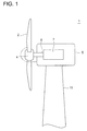
- FIG.1 is a schematic view of an overall configuration of a wind turbine generator according to an embodiment.
- a wind turbine generator according to one embodiment includes at least one wind turbine blade 2, a hub 4 to which at least one wind turbine blade 2 is attached, and a rotation shaft 6 configured to rotate the hub 4.
- the wind turbine generator 1 includes a driven unit 7 configured to be driven by the rotation shaft 6, a nacelle 5 for housing the driven unit 7, and a tower 11 for supporting the nacelle 5.
- the driven unit 7 is a synchronous generator directly connected to the rotation shaft 6.
- the driven unit 7, the driven unit 7 constitutes in part a drive train for transmitting rotational energy of the rotation shaft 6 to a generator (a synchronous generator or an induction generator) provided separately from the driven unit 7.
- the driven unit 7 is a hydraulic pump.
- the driven unit 7 is a step-up gear.
- FIG.2 is an oblique view of the wind turbine blade 2 according to an embodiment.
- the wind turbine blade 2 includes a blade body 12, a first covering layer 14A and a second covering layer 15A.
- the first covering layer 14A is provided in a first region 12A including a tip part 12E of the blade body 12 to selectively cover a leading edge 3A side of the first region 12A.
- the second covering layer 15A is provided in a second region 12B of the blade body 12 disposed nearer to the hub side than the first covering layer 14A to selectively cover the leading edge 3A side of the second region 12B.
- FIG.3A is a cross-sectional view taken along line A-A' of FIG.2 .
- FIG.3B is a cross-sectional view taken along line B-B' of FIG.2 .
- the leading edge 3A side of the first region 12A of the blade body 12 is selectively covered by the first covering layer 14A.
- the leading edge 3A side of the second region 12B of the blade body 12 is selectively covered by the second covering layer 15A.
- the wind turbine blade 2 is rotated around the hub 4 in such a state that the leading edge 3A is disposed on an upstream side in the rotating direction of the blade 2 (the direction of an arrow in the drawing) and the trailing edge 3B is disposed on a downstream side in the rotating direction of the blade 2.
- the tip speed of the blade is significantly high compared to a drop velocity of liquid droplets W.
- the tip speed vector of the wind turbine blade 2 is dominant to the impact speed vector of the liquid droplet W relative to the wind turbine blade 2. Therefore, when the wind turbine blade 2 collides with the liquid droplets W, basically the leading edge 3A side of the wind turbine blade 2 collides against the liquid droplets W.
- the first covering layer 14A provided in the first region 12A has anti-erosion properties higher than those of the second covering layer 15A provided in the second region 12B.
- anti-erosion properties is represented by the length of the incubation time Tic which is the time it takes the damage caused by the liquid-droplet erosion to become evident on a surface of the blade body 12. More specifically, the first covering layer 14A has longer erosion incubation time Tic compared to the second covering layer 15A.
- the first covering layer 14A and the second covering layer 15A selectively cover the ledge edge 3A side of the first region 12A and the second region 12B, respectively.
- at least one of the first covering layer 14A or the second covering layer 15A is provided from the leading edge 3A over to the trailing edge 3B.
- the first covering layer 14A covers from the leading edge 3A to the trailing edge 3B in the first region 12A of the blade body 12 while the second covering layer 15A covers from the leading edge 3A to the trailing edge 3B in the second region 12B of the blade body 12.
- FIG.4 is an illustration of a relationship between the operation time of the wind turbine generator 1 and weight loss of the blade body 12 caused by liquid-droplet erosion.
- the weight loss of the blade body 12 changes, starting from an incubation phase, through a steady damage phase and to a final damage phase.
- the incubation phase is a phase when damage on the surface of the blade body 12 caused by the liquid-droplet erosion is not evident yet (the weight of the blade body 12 has not decreased).
- the steady damage phase is a phase when a rate of damage caused by the liquid-droplet erosion (a rate of weight reduction of the blade body 12) becomes constant and pitting damage appears to the surface of the blade body 12.
- the final damage phase is a phase when the damage caused by the liquid-droplet erosion is severe and usefulness of the blade body 12 does not exist.
- the erosion incubation time Tic is a transition time from the incubation phase to the steady damage phase (the time that takes the incubation phase to end).
- the erosion of the blade in the incubation phase does not accompany change in appearance and thus, even if a part of the wind turbine blade 2 where erosion is evident is repaired by maintenance, there is possibility that erosion is progressing in other parts of the wind turbine blade 2 in the incubation phase.
- the leading edge 3A side of the first region 12A including the tip part 12E of the blade body 12, which is susceptible to erosion due to high tip speed, is covered by the first covering layer 14A having higher anti-erosion level than the second covering layer 15A which covers the leading edge 3A side of the second region 12B of the blade body 12 disposed on the hub side of the first covering layer 14A.
- the first covering layer 14A having higher anti-erosion level than the second covering layer 15A which covers the leading edge 3A side of the second region 12B of the blade body 12 disposed on the hub side of the first covering layer 14A.
- the first covering layer 14A having relatively high anti-erosion level on at least the ledge edge 3A of the first region 12A, it is possible to reduce the usage of the first covering layer 14A which is generally more expensive than the second covering layer 15A, thereby reducing production cost of the blade.
- the first covering layer 14A is formed by a first coating applied onto a surface of the first region 12A of the blade body 12.
- the second covering layer 15A is formed by a second coating applied onto a surface of the second region 12B of the blade body 12.
- the first coating (the first covering layer 14A) has higher resistance to erosion than the second coating (the second covering layer 15A).
- At least one of the first covering layer 14A covering the surface of the first region 12A or the second covering layer 12B covering the surface of the second region 12B includes coating whose main component is resin.
- this resin is polyurethane resin, vinylester resin or fluorine-based resin.
- the coating whose main component is polyurethane resin, vinylester resin or fluorine-based resin has high erosion resistance. By forming the coating layer to include the coating whose main component is the resin, the erosion resistance of the blade where the covering layer is formed is improved.
- At least one of the first covering layer 14A or the second coating layer 15A includes resin and particles of metal or ceramic embedded in the resin.
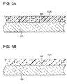
- FIG.5A is a cross-sectional view of composition of the first covering layer 14A covering the first region 14A of the blade body 12 according to one embodiment.
- FIG.5B is a cross-sectional view of composition of the second covering layer 15A covering the second region 12B of the blade body 12 according to one embodiment.
- the first covering layer 14A covering the surface of the first region 12A of the blade body includes metal particles 16 embedded in resin.
- the second covering layer 15A covering the surface of the second region 12B of the blade body 12 (the coating whose main component is resin) includes metal particles 16 embedded in resin.
- the metal particles 16 are constituted of one or more metals selected from a group including copper, stainless steel, titanium alloy and nickel alloy.
- FIG.6A is a cross-sectional view of composition of the first covering layer 14A covering the first region 12A of the blade body 12 according to one embodiment.
- FIG.6B is a cross-sectional view of composition of the second covering layer 15A covering the second region 12B of the blade body 12 according to one embodiment.
- the first covering layer 14A covering the surface of the first region 12A of the blade body includes ceramic particles 18 embedded in resin.
- the second covering layer 15A covering the surface of the second region 12B of the blade body 12 (the coating whose main component is resin) includes ceramic particles 18 embedded in resin.
- FIG.7 is a schematic representation of a test method for evaluating erosion resistance (the erosion incubation time Tic) of the covering layer.
- a covering layer 104 formed of the same material as the material forming the first covering layer 14A is provided on a surface of a test blade 101 for testing (Sample 1).
- test blade 101 with the covering layer 104 formed thereon is attached to the hub 4 and the hub 4 is rotated via a rotation shaft 106 by a motor M.
- the test blade 101 attached to the hub 4 is also rotated. Rotation of the hub causes a region of the test blade 104 where the covering layer 104 is formed to be rotated around the hub 4 at the tip speed V.
- the drawing shows precipitation intensity I of the liquid drops W, terminal velocity Vt of the liquid droplets W and a particle diameter d of the liquid drops W.
- FIG.8 is a schematic representation of a state of the liquid droplets W hitting the test blades 101. As illustrated in the drawing, the falling liquid droplets W hit the covering layer 104 at the tip speed V in a direction of forming a droplet impact angle A with respect to the vertical direction of the covering layer 104 provided on the surface of the test blade 101.
- the Precipitation intensity I, terminal velocity Vt, blade tip speed V, droplet impact angle A and particle diameter d are set constant to study change in the weight of the text blade 101. Based on the change in weight of the text blade 101 with the covering layer 104 formed thereon, the erosion incubation time t ic of the covering layer 104 is obtained (see FIG.4 ).
- a covering layer 105 formed of the same material as the material forming the second covering layer 15A is provided on the surface of the test blade 101 (Sample 2).
- the same test as Sample 1 is performed to obtain erosion incubation time tic of the covering layer 105 based on the change in weight of the test blade 101 provided with the covering layer 105 thereon.
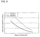
- FIG.9 is an illustration of a relationship between the tip speed of the blade and the erosion incubation time.
- the horizontal axis represents the blade tip speed (m/s) while the vertical axis represents the erosion incubation time (year).
- Sample 1 (the test blade 101 provided with the covering layer 105 formed of the same material as the material of the first covering layer 14A) shows longer erosion incubation time than Sample 2 (the test blade 101 provided with the covering layer 105 formed of the same material as the material of the second covering layer 15A).
- Sample 1 (the same material as the first covering layer 14A) has higher erosion resistance than Sample 2.
- the first covering layer 14A covering at least the ledge edge 3A of the first region 12A including the tip part 12E of the blade body 12, which is susceptible to erosion due to high tip speed, is configured to have higher erosion resistance than the second covering layer 15A covering at least the leading edge of the second region 12B of the blade body, which is disposed on a side nearer to the hub than the first covering layer 14A.
- the second covering layer 15A covering at least the leading edge of the second region 12B of the blade body which is disposed on a side nearer to the hub than the first covering layer 14A.
- the first covering layer 14A having relatively high anti-erosion properties is selectively provided on at least the leading edge 3A of the first region 12A. As a result, it is possible to reduce the usage of the first covering layer 14A which is generally more expensive than the second covering layer 15A, thereby reducing production cost of the wind turbine blade 2.
Landscapes
- Engineering & Computer Science (AREA)
- Life Sciences & Earth Sciences (AREA)
- Sustainable Development (AREA)
- Sustainable Energy (AREA)
- Chemical & Material Sciences (AREA)
- Combustion & Propulsion (AREA)
- Mechanical Engineering (AREA)
- General Engineering & Computer Science (AREA)
- Wind Motors (AREA)
Abstract
Description
- The present invention relates to a wind turbine blade and a wind turbine generator having the wind turbine blade.
- With increased environmental awareness, wind turbine generators are becoming popular. A wind turbine generator normally has a rotor with a plurality of blades attached to a hub. The rotor is installed to a nacelle which is placed on a tower installed onshore or offshore. In this type of wind turbine generator, the rotor rotates upon receiving wind on the blade, rotation of the rotor is transmitted via a drive train part to a generator housed in the nacelle, and then electric power is generated by the generator.
- In
Patent Literature 1, a blade for a wind turbine generator is disclosed. The blade includes an erosion protection coating on a blade surface to protect the blade from erosion. - [PTL 1]
US 2011/0142678 - It is know that erosion of the wind turbine generator largely relies on a collision speed (tip speed of the blade). Thus, as the length of the blade increases in accordance with the increased size of the wind turbine generator, the circumferential of the speed increases. As a result, erosion is likely to occur.
- Further, the increased length of the blade leads to a wider erosion area in the longitudinal length of the blade, in which erosion becomes evident within a prescribed period. Thus, a speed of erosion progression (an erosion speed) may differ within the erosion area. Therefore, even by repairing a portion where erosion became evident through blade maintenance, it is likely that erosion becomes evident after a short time in other portions of the blade as well.
- For this reason, the frequency of maintenance on the blade tends to become high for a long wind turbine blade.
- However, in the long wind turbine blade, the area of erosion in the longitudinal direction of the blade where erosion tends to be evident is wide. By protecting the entire area by providing an expensive coating having excellent anti-erosion properties, a production cost of the blade rises.
- In this point, there is no measure proposed in
Patent Literature 1 to suppress rise in the production cost of the blade while lowering the frequency of maintenance on the blade. - It is an object of at least one embodiment of the present invention to provide a wind turbine blade and a wind turbine generator having the wind turbine blade, which make it possible to reduce the maintenance frequency and the production cost.
- According to at least one embodiment of the present invention, a wind turbine blade attached to a hub of a wind turbine generator comprises: a blade body; a first covering layer which covers at least a leading edge in a first region including a tip part of the blade body; and a second covering layer which covers at least the leading edge in a second region of the blade body, the second region being disposed on a hub side of the first covering layer, and the first covering layer has a higher erosion resistance than the second covering layer.
- The first covering layer covers at least the leading edge of the first region including the tip part of the blade body which is susceptible to erosion due to high tip speed and the first covering layer has higher anti-erosion level than the second covering layer which covers at lest the leading edge side of the second region of the blade body disposed on the hub side of the first covering layer. As a result, it is possible to reduce the difference in the erosion rate between the first region and the second region, hence reducing the maintenance frequency of the blade.
- Further, by selectively providing the first covering layer having relatively high erosion resistance on at least the ledge edge of the first region, it is possible to reduce the usage of the first covering layer which is generally more expensive than the second covering layer, thereby reducing production cost of the blade.
- In some embodiments, the first covering layer and the second covering layer are formed by a first coating and a second coating applied on a surface of the blade body, respectively, and the first coating has a higher erosion resistance than the second coating.
- In some embodiments, at least one of the first covering layer or the second covering layer includes a coating whose main component is resin.
- In some embodiments, the coating includes particles of metal or ceramic embedded in the resin. This improves erosion resistance of the coating.
- In some embodiments, the resin is one of polyurethane resin, vinylester resin or fluorine-based resin. The coating whose main component is polyurethane resin, vinylester resin or fluorine-based resin has high erosion resistance. By forming the coating layer to include the coating whose main component is the resin, it is possible to improve the erosion resistance of the leading edge of the blade where the covering layer is formed.
- In some embodiments, the metal particles are constituted of one or more metals selected from a group including copper, stainless steel, titanium alloy and nickel alloy.
- According to at least one embodiment of the present invention, a wind turbine generator comprises at least one wind turbine blade, and the at least one wind turbine blade is provided with: a blade body; a first covering layer which covers at least a leading edge in a first region including a tip part of the blade body; and a second covering layer which covers at least the leading edge in a second region of the blade body, the second region being disposed nearer to the hub than the first covering layer, and the first covering layer has a higher erosion resistance than the second covering layer.
- As described above, the first covering layer covering at least the ledge edge of the first region including the tip part of the blade body, which is susceptible to erosion due to high tip speed, is configured to have higher erosion resistance than the second covering layer covering at least the leading edge of the second region of the blade body, which is disposed on the hub side of the first covering layer. As a result, it is possible to reduce the difference in erosion rate between the first region and the second region.
- Further, the first covering layer having relatively high anti-erosion properties is selectively provided on at least the leading edge of the first region. As a result, it is possible to reduce the usage of the first covering layer which is generally more expensive than the second covering layer, thereby reducing production cost of the wind turbine blade.
- According to at least one embodiment of the present invention, it is possible to reduce the maintenance frequency and production cost of the blade.
-
- [
FIG.1] FIG.1 is a schematic view of an overall configuration of a wind turbine generator according to an embodiment. - [
FIG.2] FIG.2 is an oblique view of a wind turbine blade according to an embodiment. - [
FIG.3A] FIG.3A is a cross-sectional view taken along line A-A' ofFIG.2 . - [
FIG.3B] FIG.3B is a cross-sectional view taken along line B-B' ofFIG.2 . - [
FIG.4] FIG.4 is an illustration of a relationship between the operation time of the wind turbine generator and weight loss of a blade body caused by liquid-droplet erosion. - [
FIG.5A] FIG.5A is a cross-sectional view of composition of a first covering layer covering a first region of the blade body according to one embodiment. - [
FIG.5B] FIG.5B is a cross-sectional view of composition of a second covering layer covering a second region of the blade body according to one embodiment. - [
FIG.6A] FIG.6A is a cross-sectional view of composition of a first covering layer covering a first region of the blade body according to one embodiment. - [
FIG.6B] FIG.6B is a cross-sectional view of composition of a second covering layer covering a second region of the blade body according to one embodiment. - [
FIG.7] FIG.7 is a schematic representation of a test method for evaluating erosion resistance of the covering layer. - [
FIG.8] FIG.8 is a schematic representation of a state of a liquid droplet impinging on a test blade. - [
FIG.9] FIG.9 is an illustration of a relationship between a tip speed of the blade and an incubation time of erosion. - Embodiments of the present invention will now be described in detail with reference to the accompanying drawings. It is intended, however, that unless particularly specified in these embodiments, dimensions, materials, shape, its relative positions and the like shall be interpreted as illustrative only and not limitative of the scope of the present invention.
-
FIG.1 is a schematic view of an overall configuration of a wind turbine generator according to an embodiment. As illustrated in the drawing, a wind turbine generator according to one embodiment includes at least onewind turbine blade 2, ahub 4 to which at least onewind turbine blade 2 is attached, and arotation shaft 6 configured to rotate thehub 4. Further, thewind turbine generator 1 includes a drivenunit 7 configured to be driven by therotation shaft 6, anacelle 5 for housing the drivenunit 7, and atower 11 for supporting thenacelle 5. - In one embodiment, the driven
unit 7 is a synchronous generator directly connected to therotation shaft 6. In another embodiment, the drivenunit 7, the drivenunit 7 constitutes in part a drive train for transmitting rotational energy of therotation shaft 6 to a generator (a synchronous generator or an induction generator) provided separately from the drivenunit 7. In the case where the drive train is a hydraulic transmission formed by a hydraulic pump and a hydraulic motor, the drivenunit 7 is a hydraulic pump. In the case where the drive train includes a step-up gear, the drivenunit 7 is a step-up gear. -
FIG.2 is an oblique view of thewind turbine blade 2 according to an embodiment. As illustrated in the drawing, in one embodiment, thewind turbine blade 2 includes ablade body 12, afirst covering layer 14A and asecond covering layer 15A. Thefirst covering layer 14A is provided in afirst region 12A including atip part 12E of theblade body 12 to selectively cover aleading edge 3A side of thefirst region 12A. Thesecond covering layer 15A is provided in asecond region 12B of theblade body 12 disposed nearer to the hub side than thefirst covering layer 14A to selectively cover theleading edge 3A side of thesecond region 12B. -
FIG.3A is a cross-sectional view taken along line A-A' ofFIG.2 .FIG.3B is a cross-sectional view taken along line B-B' ofFIG.2 . As illustrated inFIG.3A , the leadingedge 3A side of thefirst region 12A of theblade body 12 is selectively covered by thefirst covering layer 14A. As illustrated inFIG.3B , the leadingedge 3A side of thesecond region 12B of theblade body 12 is selectively covered by thesecond covering layer 15A. - As illustrated in
FIG.2 , during operation of thewind turbine generator 1, thewind turbine blade 2 is rotated around thehub 4 in such a state that theleading edge 3A is disposed on an upstream side in the rotating direction of the blade 2 (the direction of an arrow in the drawing) and the trailingedge 3B is disposed on a downstream side in the rotating direction of theblade 2. The tip speed of the blade is significantly high compared to a drop velocity of liquid droplets W. Thus, the tip speed vector of thewind turbine blade 2 is dominant to the impact speed vector of the liquid droplet W relative to thewind turbine blade 2. Therefore, when thewind turbine blade 2 collides with the liquid droplets W, basically theleading edge 3A side of thewind turbine blade 2 collides against the liquid droplets W. - By covering at least the
leading edge 3A of theblade body 12 with the covering layers 14A, 15A, it is possible to reduce erosion of theblade body 12 caused by the collision against the liquid droplets W. - The
first covering layer 14A provided in thefirst region 12A has anti-erosion properties higher than those of thesecond covering layer 15A provided in thesecond region 12B. - Herein, "anti-erosion properties" is represented by the length of the incubation time Tic which is the time it takes the damage caused by the liquid-droplet erosion to become evident on a surface of the
blade body 12. More specifically, thefirst covering layer 14A has longer erosion incubation time Tic compared to thesecond covering layer 15A. - In the embodiments illustrated in
FIG.2 andFIG.3 , thefirst covering layer 14A and thesecond covering layer 15A selectively cover theledge edge 3A side of thefirst region 12A and thesecond region 12B, respectively. In another embodiment, at least one of thefirst covering layer 14A or thesecond covering layer 15A is provided from theleading edge 3A over to the trailingedge 3B. - For instance, the
first covering layer 14A covers from theleading edge 3A to the trailingedge 3B in thefirst region 12A of theblade body 12 while thesecond covering layer 15A covers from theleading edge 3A to the trailingedge 3B in thesecond region 12B of theblade body 12. -
FIG.4 is an illustration of a relationship between the operation time of thewind turbine generator 1 and weight loss of theblade body 12 caused by liquid-droplet erosion. As illustrated in the drawing, the weight loss of theblade body 12 changes, starting from an incubation phase, through a steady damage phase and to a final damage phase. The incubation phase is a phase when damage on the surface of theblade body 12 caused by the liquid-droplet erosion is not evident yet (the weight of theblade body 12 has not decreased). The steady damage phase is a phase when a rate of damage caused by the liquid-droplet erosion (a rate of weight reduction of the blade body 12) becomes constant and pitting damage appears to the surface of theblade body 12. The final damage phase is a phase when the damage caused by the liquid-droplet erosion is severe and usefulness of theblade body 12 does not exist. The erosion incubation time Tic is a transition time from the incubation phase to the steady damage phase (the time that takes the incubation phase to end). - As described, the erosion of the blade in the incubation phase does not accompany change in appearance and thus, even if a part of the
wind turbine blade 2 where erosion is evident is repaired by maintenance, there is possibility that erosion is progressing in other parts of thewind turbine blade 2 in the incubation phase. - Therefore, in the case where an area in the longitudinal direction of the
blade 2 where erosion might become evident is large and the speed of erosion progression (erosion speed) tends to vary in the area, the maintenance frequency of thewind turbine blade 2 becomes high. - In view of this, the leading
edge 3A side of thefirst region 12A including thetip part 12E of theblade body 12, which is susceptible to erosion due to high tip speed, is covered by thefirst covering layer 14A having higher anti-erosion level than thesecond covering layer 15A which covers theleading edge 3A side of thesecond region 12B of theblade body 12 disposed on the hub side of thefirst covering layer 14A. As a result, it is possible to reduce the difference in the erosion rate between thefirst region 12A and thesecond region 12B, hence reducing the maintenance frequency of the blade. - Further, by selectively providing the
first covering layer 14A having relatively high anti-erosion level on at least theledge edge 3A of thefirst region 12A, it is possible to reduce the usage of thefirst covering layer 14A which is generally more expensive than thesecond covering layer 15A, thereby reducing production cost of the blade. - In one embodiment, the
first covering layer 14A is formed by a first coating applied onto a surface of thefirst region 12A of theblade body 12. Thesecond covering layer 15A is formed by a second coating applied onto a surface of thesecond region 12B of theblade body 12. The first coating (thefirst covering layer 14A) has higher resistance to erosion than the second coating (thesecond covering layer 15A). - In one embodiment, at least one of the
first covering layer 14A covering the surface of thefirst region 12A or thesecond covering layer 12B covering the surface of thesecond region 12B includes coating whose main component is resin. In some embodiments, this resin is polyurethane resin, vinylester resin or fluorine-based resin. The coating whose main component is polyurethane resin, vinylester resin or fluorine-based resin has high erosion resistance. By forming the coating layer to include the coating whose main component is the resin, the erosion resistance of the blade where the covering layer is formed is improved. - In one embodiment, at least one of the
first covering layer 14A or thesecond coating layer 15A includes resin and particles of metal or ceramic embedded in the resin. -
FIG.5A is a cross-sectional view of composition of thefirst covering layer 14A covering thefirst region 14A of theblade body 12 according to one embodiment.FIG.5B is a cross-sectional view of composition of thesecond covering layer 15A covering thesecond region 12B of theblade body 12 according to one embodiment. - As illustrated in these two drawings, in one embodiment, the
first covering layer 14A covering the surface of thefirst region 12A of the blade body (the coating whose main component is resin) includesmetal particles 16 embedded in resin. In one embodiment, thesecond covering layer 15A covering the surface of thesecond region 12B of the blade body 12 (the coating whose main component is resin) includesmetal particles 16 embedded in resin. As a result, the erosion resistance of the coating is improved. In some embodiments, themetal particles 16 are constituted of one or more metals selected from a group including copper, stainless steel, titanium alloy and nickel alloy. -
FIG.6A is a cross-sectional view of composition of thefirst covering layer 14A covering thefirst region 12A of theblade body 12 according to one embodiment.FIG.6B is a cross-sectional view of composition of thesecond covering layer 15A covering thesecond region 12B of theblade body 12 according to one embodiment. - As illustrated in these two drawings, in one embodiment, the
first covering layer 14A covering the surface of thefirst region 12A of the blade body (the coating whose main component is resin) includesceramic particles 18 embedded in resin. In one embodiment, thesecond covering layer 15A covering the surface of thesecond region 12B of the blade body 12 (the coating whose main component is resin) includesceramic particles 18 embedded in resin. As a result, the erosion resistance of the coating is improved. - Next, a method for evaluating the erosion resistance of each of the covering layers 14A, 15A is described in reference to
FIG.7 to FIG.9 .FIG.7 is a schematic representation of a test method for evaluating erosion resistance (the erosion incubation time Tic) of the covering layer. As illustrated in the drawing, acovering layer 104 formed of the same material as the material forming thefirst covering layer 14A is provided on a surface of atest blade 101 for testing (Sample 1). - Next, the
test blade 101 with thecovering layer 104 formed thereon is attached to thehub 4 and thehub 4 is rotated via arotation shaft 106 by a motor M. By rotating thehub 4, thetest blade 101 attached to thehub 4 is also rotated. Rotation of the hub causes a region of thetest blade 104 where thecovering layer 104 is formed to be rotated around thehub 4 at the tip speed V. - Next, a large amount of liquid droplets (raindrops) is dropped from above the
test blade 101. The drawing shows precipitation intensity I of the liquid drops W, terminal velocity Vt of the liquid droplets W and a particle diameter d of the liquid drops W. -
FIG.8 is a schematic representation of a state of the liquid droplets W hitting thetest blades 101. As illustrated in the drawing, the falling liquid droplets W hit thecovering layer 104 at the tip speed V in a direction of forming a droplet impact angle A with respect to the vertical direction of thecovering layer 104 provided on the surface of thetest blade 101. - The Precipitation intensity I, terminal velocity Vt, blade tip speed V, droplet impact angle A and particle diameter d are set constant to study change in the weight of the
text blade 101. Based on the change in weight of thetext blade 101 with thecovering layer 104 formed thereon, the erosion incubation time tic of thecovering layer 104 is obtained (seeFIG.4 ). - Next, a
covering layer 105 formed of the same material as the material forming thesecond covering layer 15A is provided on the surface of the test blade 101 (Sample 2). Under the same conditions as Sample 1 (the same precipitation intensity I, terminal velocity Vt, blade tip speed V, droplet impact angle A and particle diameter d as those used for Sample 1), the same test asSample 1 is performed to obtain erosion incubation time tic of thecovering layer 105 based on the change in weight of thetest blade 101 provided with thecovering layer 105 thereon. -
FIG.9 is an illustration of a relationship between the tip speed of the blade and the erosion incubation time. The horizontal axis represents the blade tip speed (m/s) while the vertical axis represents the erosion incubation time (year). As illustrated in the drawing, Sample 1 (thetest blade 101 provided with thecovering layer 105 formed of the same material as the material of thefirst covering layer 14A) shows longer erosion incubation time than Sample 2 (thetest blade 101 provided with thecovering layer 105 formed of the same material as the material of thesecond covering layer 15A). In other words, Sample 1 (the same material as thefirst covering layer 14A) has higher erosion resistance thanSample 2. - As described above, according to the
wind turbine blade 2 of at least one embodiment of the present invention, thefirst covering layer 14A covering at least theledge edge 3A of thefirst region 12A including thetip part 12E of theblade body 12, which is susceptible to erosion due to high tip speed, is configured to have higher erosion resistance than thesecond covering layer 15A covering at least the leading edge of thesecond region 12B of the blade body, which is disposed on a side nearer to the hub than thefirst covering layer 14A. As a result, it is possible to reduce the difference in erosion rate between thefirst region 12A and thesecond region 12B. - Further, the
first covering layer 14A having relatively high anti-erosion properties is selectively provided on at least theleading edge 3A of thefirst region 12A. As a result, it is possible to reduce the usage of thefirst covering layer 14A which is generally more expensive than thesecond covering layer 15A, thereby reducing production cost of thewind turbine blade 2. - While the embodiments of the present invention have been described, it is obvious to those skilled in the art that various changes and modification may be made without departing from the scope of the invention.
-
- 1
- Wind turbine generator
- 2
- Wind turbine blade
- 3A
- Leading edge
- 3B
- Trailing edge
- 4
- Hub
- 5
- Nacelle
- 6, 106
- Rotation shaft
- 7
- Driven unit
- 11
- Tower
- 12
- Blade body
- 12E
- Tip part
- 12A
- First region
- 12B
- Second region
- 14A
- First covering layer
- 14B
- First coating
- 15A
- Second covering layer
- 15B
- Second coating
- 16
- Metal particle
- 18
- Ceramic particle
- 101
- Test blade
- 104, 105
- Covering layer
- tit
- Erosion incubation time
- I
- Precipitation intensity
- V
- Blade tip speed
- Vt
- Terminal velocity
- A
- Droplet impact angle
- W
- Liquid droplet
- D
- Particle diameter
- M
- Motor
Claims (7)
- A wind turbine blade attached to a hub of a wind turbine generator, the wind turbine blade comprising:a blade body;a first covering layer which covers at least a leading edge in a first region including a tip part of the blade body; anda second covering layer which covers at least the leading edge in a second region of the blade body, the second region being disposed on a hub side of the first covering layer,wherein the first covering layer has a higher erosion resistance than the second covering layer.
- The wind turbine blade according to claim 1,
wherein the first covering layer and the second covering layer are formed by a first coating and a second coating applied on a surface of the blade body, respectively, and
wherein the first coating has a higher erosion resistance than the second coating. - The wind turbine blade according to claim 1 or 2,
wherein at least one of the first covering layer or the second covering layer includes a coating whose main component is resin. - The wind turbine blade according to claim 3,
wherein the coating includes particles of metal or ceramic embedded in the resin. - The wind turbine blade according to claim 3 or 4,
wherein the resin is one of polyurethane resin, vinylester resin or fluorine-based resin. - The wind turbine blade according to claim 4,
wherein the metal particles are constituted of one or more metals selected from a group including copper, stainless steel, titanium alloy and nickel alloy. - A wind turbine generator comprising at least one wind turbine blade,
wherein the at least one blade comprises:a blade body;a first covering layer which covers at least a leading edge in a first region including a tip part of the blade body; anda second covering layer which covers at least the leading edge in a second region of the blade body, the second region being disposed nearer to the hub than the first covering layer, andwherein the first covering layer has a higher erosion resistance than the second covering layer.
Applications Claiming Priority (1)
| Application Number | Priority Date | Filing Date | Title |
|---|---|---|---|
| PCT/JP2012/083833 WO2014102957A1 (en) | 2012-12-27 | 2012-12-27 | Wind turbine rotor blade and wind turbine generator with same |
Publications (2)
| Publication Number | Publication Date |
|---|---|
| EP2868920A1 true EP2868920A1 (en) | 2015-05-06 |
| EP2868920A4 EP2868920A4 (en) | 2015-08-05 |
Family
ID=51017399
Family Applications (1)
| Application Number | Title | Priority Date | Filing Date |
|---|---|---|---|
| EP12891280.5A Withdrawn EP2868920A4 (en) | 2012-12-27 | 2012-12-27 | Wind turbine rotor blade and wind turbine generator with same |
Country Status (4)
| Country | Link |
|---|---|
| US (1) | US20140186188A1 (en) |
| EP (1) | EP2868920A4 (en) |
| JP (1) | JP5980350B2 (en) |
| WO (1) | WO2014102957A1 (en) |
Cited By (4)
| Publication number | Priority date | Publication date | Assignee | Title |
|---|---|---|---|---|
| WO2018060299A1 (en) * | 2016-09-27 | 2018-04-05 | Siemens Aktiengesellschaft | Protective cover system |
| EP3504428A1 (en) * | 2016-09-27 | 2019-07-03 | Siemens Gamesa Renewable Energy A/S | Protective cover system for protecting a leading edge of a wind turbine rotor blade |
| WO2022029214A1 (en) * | 2020-08-05 | 2022-02-10 | Blade Dynamics Limited | Leading edge protection for a wind turbine blade |
| US11493020B2 (en) | 2018-11-16 | 2022-11-08 | Mitsubishi Heavy Industries, Ltd. | Wind turbine blade and method for manufacturing the same |
Families Citing this family (28)
| Publication number | Priority date | Publication date | Assignee | Title |
|---|---|---|---|---|
| US10357931B2 (en) * | 2013-11-19 | 2019-07-23 | Lm Wp Patent Holding A/S | System and method for manufacturing a wind turbine blade component |
| WO2016075619A1 (en) | 2014-11-10 | 2016-05-19 | Polytech A/S | Polyurethane material, process for preparing such material and protective cover for wind turbine blade |
| GB201508827D0 (en) * | 2015-05-22 | 2015-07-01 | Sanderson Simon | Aerodynamic shroud and method |
| DK201570881A1 (en) * | 2015-05-26 | 2017-01-30 | Blade Repair Solutions Ivs | A method for establishing erosion resistant surface on a wind turbine blade, process for the formation of an erosion-resistant coating, wind turbine blade with retrofitted coating in and around the areas where the wing is particularly prone to erosion damage coating for mounting on a wind turbine forefront. |
| JP6421078B2 (en) * | 2015-05-28 | 2018-11-07 | エムエイチアイ ヴェスタス オフショア ウィンド エー/エス | Wind turbine blade and wind power generator, and method for manufacturing or modifying wind turbine blade |
| US10533533B2 (en) * | 2015-08-26 | 2020-01-14 | General Electric Company | Modular wind turbine rotor blade constructed of multiple resin systems |
| DE102015115190A1 (en) * | 2015-09-09 | 2017-03-09 | Fichtner & Schicht GmbH | Wind turbine |
| US10933988B2 (en) | 2015-12-18 | 2021-03-02 | Amazon Technologies, Inc. | Propeller blade treatments for sound control |
| US10259574B2 (en) | 2015-12-18 | 2019-04-16 | Amazon Technologies, Inc. | Propeller surface area treatments for sound dampening |
| US10099773B2 (en) | 2015-12-18 | 2018-10-16 | Amazon Technologies, Inc. | Propeller blade leading edge serrations for improved sound control |
| US10011346B2 (en) | 2015-12-18 | 2018-07-03 | Amazon Technologies, Inc. | Propeller blade indentations for improved aerodynamic performance and sound control |
| US10259562B2 (en) | 2015-12-18 | 2019-04-16 | Amazon Technologies, Inc. | Propeller blade trailing edge fringes for improved sound control |
| EP3747764B1 (en) * | 2015-12-18 | 2022-09-28 | Amazon Technologies, Inc. | Propeller blade treatments for sound control |
| US10460717B2 (en) | 2015-12-18 | 2019-10-29 | Amazon Technologies, Inc. | Carbon nanotube transducers on propeller blades for sound control |
| JP6726028B2 (en) * | 2016-05-30 | 2020-07-22 | 株式会社東芝 | Turbine blade, method of manufacturing turbine blade, and turbine equipment |
| WO2018091056A1 (en) * | 2016-11-18 | 2018-05-24 | Mhi Vestas Offshore Wind A/S | Controlling wind turbine based on rain drop size |
| EP3542055B1 (en) * | 2016-11-18 | 2021-09-29 | Vestas Offshore Wind A/S | Operating wind turbine above rating during low erosion conditions |
| JP2018150868A (en) * | 2017-03-13 | 2018-09-27 | 株式会社Ihi | Water flow power generator |
| EP3601782B1 (en) | 2017-03-21 | 2021-07-14 | Vestas Offshore Wind A/S | Wind turbine blade, wind turbine rotor, and wind turbine power generating apparatus |
| WO2018196967A1 (en) * | 2017-04-26 | 2018-11-01 | Mhi Vestas Offshore Wind A/S | Wind turbine blade and wind turbine power generating apparatus |
| JP2018197517A (en) * | 2017-05-23 | 2018-12-13 | 株式会社Ihi | Water flow power generation device |
| ES2957264T3 (en) | 2017-05-31 | 2024-01-16 | Siemens Gamesa Renewable Energy As | Protective shield with positioning mark |
| DK179701B1 (en) * | 2017-09-06 | 2019-04-02 | Blade Repair Solutions Ivs | A method for reinforcing a wind turbine blade |
| US10920742B2 (en) * | 2018-07-26 | 2021-02-16 | Institute of Nuclear Energy Research, Atomic Energy Council, Executive Yuan, R.O.C. | Noise-reduction device for wind turbine and the wind turbine applied thereof |
| US11163302B2 (en) | 2018-09-06 | 2021-11-02 | Amazon Technologies, Inc. | Aerial vehicle propellers having variable force-torque ratios |
| US11441545B2 (en) * | 2020-02-25 | 2022-09-13 | General Electric Company | Tungsten-based erosion-resistant leading edge protection cap for rotor blades |
| JP7519811B2 (en) * | 2020-05-25 | 2024-07-22 | 三菱重工業株式会社 | Wind turbine blade, wind turbine, and method for repairing wind turbine blade |
| WO2023280838A1 (en) * | 2021-07-06 | 2023-01-12 | Lm Wind Power A/S | Wind turbine blade having an electro-thermal system |
Family Cites Families (18)
| Publication number | Priority date | Publication date | Assignee | Title |
|---|---|---|---|---|
| US5531369A (en) * | 1993-08-02 | 1996-07-02 | Electric Power Research Institute | Process for making machines resistant to cavitation and liquid droplet erosion |
| US5486096A (en) * | 1994-06-30 | 1996-01-23 | United Technologies Corporation | Erosion resistant surface protection |
| US5782607A (en) * | 1996-12-11 | 1998-07-21 | United Technologies Corporation | Replaceable ceramic blade insert |
| US5908522A (en) * | 1997-11-07 | 1999-06-01 | Composite Technology, Inc. | Supplemental leading edge wear strip for a rotor blade |
| US6341747B1 (en) * | 1999-10-28 | 2002-01-29 | United Technologies Corporation | Nanocomposite layered airfoil |
| US20040118978A1 (en) * | 2002-12-24 | 2004-06-24 | Anning Bruce D. | Helicopter rotor and method of repairing same |
| US20080159870A1 (en) * | 2006-12-14 | 2008-07-03 | Hontek Corporation | Method and coating for protecting and repairing an airfoil surface using molded boots, sheet or tape |
| JP2007170328A (en) * | 2005-12-26 | 2007-07-05 | Toray Ind Inc | Wind turbine blade for wind power generation and method for manufacturing the same |
| US8088498B2 (en) * | 2007-05-23 | 2012-01-03 | Hamilton Sundstrand Corporation | Electro-formed sheath for use on airfoil components |
| US20090220795A1 (en) * | 2008-02-29 | 2009-09-03 | Ppg Industries Ohio, Inc. | Composites comprising a multi-layer coating system |
| US7988421B2 (en) * | 2009-03-31 | 2011-08-02 | General Electric Company | Retrofit sleeve for wind turbine blade |
| DE202009006966U1 (en) * | 2009-04-14 | 2010-09-02 | Gummiwerk Kraiburg Gmbh & Co. Kg | Composite components made of thermosetting resins and elastomers |
| US8247050B2 (en) * | 2009-06-02 | 2012-08-21 | Integran Technologies, Inc. | Metal-coated polymer article of high durability and vacuum and/or pressure integrity |
| US9028969B2 (en) * | 2010-07-27 | 2015-05-12 | United Technologies Corporation | Composite article having protective coating |
| US20110142678A1 (en) | 2010-11-23 | 2011-06-16 | General Electric Company | Erosion protection coating for rotor blade of wind turbine |
| KR101315841B1 (en) * | 2011-01-26 | 2013-10-14 | 후지쿠라 고무 코교 가부시끼가이샤 | Wing blade and laminated protective sheet thereof |
| US8425196B2 (en) * | 2011-01-28 | 2013-04-23 | General Electric Company | Wind turbine blades with a hardened substrate construction |
| CN202215428U (en) * | 2011-09-07 | 2012-05-09 | 新疆鑫风麒能源服务股份有限公司 | Vane for wind generating set |
-
2012
- 2012-12-27 EP EP12891280.5A patent/EP2868920A4/en not_active Withdrawn
- 2012-12-27 WO PCT/JP2012/083833 patent/WO2014102957A1/en not_active Ceased
- 2012-12-27 JP JP2014553958A patent/JP5980350B2/en active Active
-
2013
- 2013-12-23 US US14/138,872 patent/US20140186188A1/en not_active Abandoned
Cited By (10)
| Publication number | Priority date | Publication date | Assignee | Title |
|---|---|---|---|---|
| WO2018060299A1 (en) * | 2016-09-27 | 2018-04-05 | Siemens Aktiengesellschaft | Protective cover system |
| EP3504428A1 (en) * | 2016-09-27 | 2019-07-03 | Siemens Gamesa Renewable Energy A/S | Protective cover system for protecting a leading edge of a wind turbine rotor blade |
| CN110036199A (en) * | 2016-09-27 | 2019-07-19 | 西门子歌美飒可再生能源公司 | protective cover system |
| CN110088466A (en) * | 2016-09-27 | 2019-08-02 | 西门子歌美飒可再生能源公司 | Guard system for protecting the leading edge of a wind turbine rotor blade |
| US11274653B2 (en) | 2016-09-27 | 2022-03-15 | Siemens Gamesa Renewable Energy A/S | Protective cover system |
| US11421661B2 (en) | 2016-09-27 | 2022-08-23 | Siemens Gamesa Renewable Energy A/S | Protective cover system for protecting a leading edge of a wind turbine rotor blade |
| CN110088466B (en) * | 2016-09-27 | 2024-03-22 | 西门子歌美飒可再生能源公司 | Protective cover system for protecting the leading edge of a wind turbine rotor blade |
| US11493020B2 (en) | 2018-11-16 | 2022-11-08 | Mitsubishi Heavy Industries, Ltd. | Wind turbine blade and method for manufacturing the same |
| US11891976B2 (en) | 2018-11-16 | 2024-02-06 | Mitsubishi Heavy Industries, Ltd. | Wind turbine blade and method for manufacturing the same |
| WO2022029214A1 (en) * | 2020-08-05 | 2022-02-10 | Blade Dynamics Limited | Leading edge protection for a wind turbine blade |
Also Published As
| Publication number | Publication date |
|---|---|
| US20140186188A1 (en) | 2014-07-03 |
| JP5980350B2 (en) | 2016-08-31 |
| EP2868920A4 (en) | 2015-08-05 |
| JPWO2014102957A1 (en) | 2017-01-12 |
| WO2014102957A1 (en) | 2014-07-03 |
Similar Documents
| Publication | Publication Date | Title |
|---|---|---|
| US20140186188A1 (en) | Wind turbine blade and wind turbine generator havign the same | |
| EP3536947B1 (en) | Protective cover for protecting a leading edge of a wind turbine blade | |
| EP2604794B1 (en) | Electrical Grounding for Fan Blades | |
| JP5033033B2 (en) | Method for measuring turbulence intensity of horizontal axis wind turbine | |
| EP3098438B1 (en) | Wind turbine blade and wind turbine power generating apparatus, and method of producing or retrofitting wind turbine blade | |
| EP4321752A1 (en) | Wing structure and wing structure manufacturing method | |
| EP2412971B1 (en) | Fluid machine utilizing unsteady flow, windmill, and method for increasing velocity of internal flow of fluid machine | |
| US20110142678A1 (en) | Erosion protection coating for rotor blade of wind turbine | |
| CN111727317B (en) | Determining icing conditions using mechanical wind sensors | |
| EP2169217A1 (en) | Wind generator blade | |
| CN105756865A (en) | Rotor Blade Extension Part | |
| EP2971528B2 (en) | Hollow fan blade with extended wing sheath | |
| WO2013000810A3 (en) | Method of controlling a wind turbine and related system | |
| WO2010007342A3 (en) | Tidal turbine system | |
| WO2008093540A1 (en) | Wind-driven generator | |
| KR20090083341A (en) | Wind power generator | |
| EP2895699B1 (en) | Electrical grounding for blade sheath | |
| EP3462016A1 (en) | Use of a new material in wind turbine parts and apparatus and methods hereof | |
| JP5134629B2 (en) | Wind turbine blade and wind power generator using the same | |
| EP2455611A2 (en) | Pitch system balancing for a wind turbine | |
| CN108474258B (en) | main edge guard | |
| EP3351734B1 (en) | Fan blade with anode and method for galvanic corrosion mitigation | |
| WO2013076234A3 (en) | Wind turbine rotor | |
| KR20190085080A (en) | Wind turbine control based on raindrop size | |
| EP2730778A1 (en) | Natural energy extraction device |
Legal Events
| Date | Code | Title | Description |
|---|---|---|---|
| PUAI | Public reference made under article 153(3) epc to a published international application that has entered the european phase |
Free format text: ORIGINAL CODE: 0009012 |
|
| 17P | Request for examination filed |
Effective date: 20150129 |
|
| AK | Designated contracting states |
Kind code of ref document: A1 Designated state(s): AL AT BE BG CH CY CZ DE DK EE ES FI FR GB GR HR HU IE IS IT LI LT LU LV MC MK MT NL NO PL PT RO RS SE SI SK SM TR |
|
| AX | Request for extension of the european patent |
Extension state: BA ME |
|
| RA4 | Supplementary search report drawn up and despatched (corrected) |
Effective date: 20150703 |
|
| RIC1 | Information provided on ipc code assigned before grant |
Ipc: F03D 1/06 20060101AFI20150629BHEP |
|
| DAX | Request for extension of the european patent (deleted) | ||
| 17Q | First examination report despatched |
Effective date: 20180125 |
|
| STAA | Information on the status of an ep patent application or granted ep patent |
Free format text: STATUS: THE APPLICATION IS DEEMED TO BE WITHDRAWN |
|
| 18D | Application deemed to be withdrawn |
Effective date: 20181123 |