EP2868895A1 - Turbo rotational frequency detection device - Google Patents
Turbo rotational frequency detection device Download PDFInfo
- Publication number
- EP2868895A1 EP2868895A1 EP13808441.3A EP13808441A EP2868895A1 EP 2868895 A1 EP2868895 A1 EP 2868895A1 EP 13808441 A EP13808441 A EP 13808441A EP 2868895 A1 EP2868895 A1 EP 2868895A1
- Authority
- EP
- European Patent Office
- Prior art keywords
- rotational frequency
- flow rate
- compressor
- entry
- intake air
- Prior art date
- Legal status (The legal status is an assumption and is not a legal conclusion. Google has not performed a legal analysis and makes no representation as to the accuracy of the status listed.)
- Withdrawn
Links
Images

Classifications
-
- G—PHYSICS
- G01—MEASURING; TESTING
- G01M—TESTING STATIC OR DYNAMIC BALANCE OF MACHINES OR STRUCTURES; TESTING OF STRUCTURES OR APPARATUS, NOT OTHERWISE PROVIDED FOR
- G01M15/00—Testing of engines
- G01M15/14—Testing gas-turbine engines or jet-propulsion engines
-
- F—MECHANICAL ENGINEERING; LIGHTING; HEATING; WEAPONS; BLASTING
- F02—COMBUSTION ENGINES; HOT-GAS OR COMBUSTION-PRODUCT ENGINE PLANTS
- F02B—INTERNAL-COMBUSTION PISTON ENGINES; COMBUSTION ENGINES IN GENERAL
- F02B39/00—Component parts, details, or accessories relating to, driven charging or scavenging pumps, not provided for in groups F02B33/00 - F02B37/00
- F02B39/16—Other safety measures for, or other control of, pumps
-
- F—MECHANICAL ENGINEERING; LIGHTING; HEATING; WEAPONS; BLASTING
- F02—COMBUSTION ENGINES; HOT-GAS OR COMBUSTION-PRODUCT ENGINE PLANTS
- F02B—INTERNAL-COMBUSTION PISTON ENGINES; COMBUSTION ENGINES IN GENERAL
- F02B37/00—Engines characterised by provision of pumps driven at least for part of the time by exhaust
- F02B37/12—Control of the pumps
- F02B2037/122—Control of rotational speed of the pump
-
- F—MECHANICAL ENGINEERING; LIGHTING; HEATING; WEAPONS; BLASTING
- F02—COMBUSTION ENGINES; HOT-GAS OR COMBUSTION-PRODUCT ENGINE PLANTS
- F02B—INTERNAL-COMBUSTION PISTON ENGINES; COMBUSTION ENGINES IN GENERAL
- F02B39/00—Component parts, details, or accessories relating to, driven charging or scavenging pumps, not provided for in groups F02B33/00 - F02B37/00
- F02B39/16—Other safety measures for, or other control of, pumps
- F02B2039/162—Control of pump parameters to improve safety thereof
- F02B2039/168—Control of pump parameters to improve safety thereof the rotational speed of pump or exhaust drive being limited
-
- F—MECHANICAL ENGINEERING; LIGHTING; HEATING; WEAPONS; BLASTING
- F02—COMBUSTION ENGINES; HOT-GAS OR COMBUSTION-PRODUCT ENGINE PLANTS
- F02D—CONTROLLING COMBUSTION ENGINES
- F02D2200/00—Input parameters for engine control
- F02D2200/02—Input parameters for engine control the parameters being related to the engine
- F02D2200/04—Engine intake system parameters
- F02D2200/0402—Engine intake system parameters the parameter being determined by using a model of the engine intake or its components
-
- F—MECHANICAL ENGINEERING; LIGHTING; HEATING; WEAPONS; BLASTING
- F02—COMBUSTION ENGINES; HOT-GAS OR COMBUSTION-PRODUCT ENGINE PLANTS
- F02D—CONTROLLING COMBUSTION ENGINES
- F02D2200/00—Input parameters for engine control
- F02D2200/02—Input parameters for engine control the parameters being related to the engine
- F02D2200/04—Engine intake system parameters
- F02D2200/0406—Intake manifold pressure
-
- F—MECHANICAL ENGINEERING; LIGHTING; HEATING; WEAPONS; BLASTING
- F02—COMBUSTION ENGINES; HOT-GAS OR COMBUSTION-PRODUCT ENGINE PLANTS
- F02D—CONTROLLING COMBUSTION ENGINES
- F02D2200/00—Input parameters for engine control
- F02D2200/02—Input parameters for engine control the parameters being related to the engine
- F02D2200/04—Engine intake system parameters
- F02D2200/0414—Air temperature
-
- F—MECHANICAL ENGINEERING; LIGHTING; HEATING; WEAPONS; BLASTING
- F02—COMBUSTION ENGINES; HOT-GAS OR COMBUSTION-PRODUCT ENGINE PLANTS
- F02D—CONTROLLING COMBUSTION ENGINES
- F02D41/00—Electrical control of supply of combustible mixture or its constituents
- F02D41/0002—Controlling intake air
- F02D41/0007—Controlling intake air for control of turbo-charged or super-charged engines
-
- F—MECHANICAL ENGINEERING; LIGHTING; HEATING; WEAPONS; BLASTING
- F02—COMBUSTION ENGINES; HOT-GAS OR COMBUSTION-PRODUCT ENGINE PLANTS
- F02D—CONTROLLING COMBUSTION ENGINES
- F02D41/00—Electrical control of supply of combustible mixture or its constituents
- F02D41/02—Circuit arrangements for generating control signals
- F02D41/18—Circuit arrangements for generating control signals by measuring intake air flow
Definitions
- the present invention relates to a turbo rotational frequency detection device.
- a disc with a circumferential notch is integrally fitted over a rotary shaft interconnecting the turbine and the compressor of the turbocharger.
- a non-contact sensor which grasps passing of the notch of the disc as, for example, change in a magnetic field so that the passing of the notch of the disc is detected and counted by the sensor, whereby a rotational frequency of the turbocharger can be monitored.
- cases increase where no spatial room is left between the turbine and the compressor due to pipings of, for example, cooling water and lubrication oil so that the disc and the non-contact sensor cannot be physically arranged.
- Patent Literature 1 As conventional art document pertinent to the invention.
- the invention was made in view of the above and has its object to provide a turbo rotational frequency detection device capable of determining a rotational frequency of a turbocharger without a rotation sensor.
- the invention is directed to a turbo rotational frequency detection device comprising first and second pressure sensors for detecting entry and exit pressures of a compressor, respectively, intake flow rate and temperature sensors for detecting a mass flow rate and an entry temperature of intake air, respectively, and an arithmetic device for digitally storing an operating characteristic diagram showing equal rotational frequency lines of the compressor in a turbocharger in terms of a volumetric flow rate of the intake air and a pressure ratio under a standard environmental condition where the entry pressure of the compressor and the entry temperature of the intake air are predetermined standard values, said arithmetic device being adapted to calculate a pressure ratio of said compressor on the basis of the entry and exit pressures of the compressor detected by the first and second pressure sensors, respectively, and calculate a volumetric flow rate of the intake air under an environmental condition at a time of detection using a gas state equation on the basis of the mass flow rate and the entry temperature of the intake air detected by the intake flow rate and temperature sensors, respectively, and said entry pressure of the compressor, correct the calculated volumetric flow rate into a volume
- a compressor in general has a characteristic that if a pressure ratio (ratio of entry and exit pressures) of the compressor rotated at a rotational frequency is determined, a volumetric flow rate of intake air in the compressor is unambiguously determined, so that experimentally obtained equal rotational frequency lines can be plotted on a graph with an ordinate representing a pressure ratio and an abscissa representing a volumetric flow rate of the intake air.
- a rotational frequency can be read out from the pressure ratio and the volumetric flow rate.
- the above-mentioned operating characteristic diagram comes into effect under an environmental condition with a single entry temperature and a single entry pressure; even if the intake air has the same mass flow rate, the volumetric flow rate may become greater due to expansion provided that the entry temperature becomes higher or the entry pressure becomes lower.
- the calculated volumetric flow rate is corrected into a corrected volumetric flow rate under the standard environmental condition through multiplication by the corrective coefficient on the basis of the entry temperature of the intake air.
- a rotational frequency of the compressor under the standard environmental condition can be read out in light of the operating characteristic diagram.
- the corrective coefficient is a square root of a quotient obtained through division of the entry temperature (absolute temperature detected by the intake temperature sensor) at the time of detection by the entry temperature (absolute temperature) under the standard environmental condition.
- the multiplication by such corrective coefficient enables the correction into the volumetric flow rate under the standard environmental condition, which is due to gas similarity rule.
- the rotational frequency read out in light of the operating characteristic diagram is the rotational frequency of the compressor under the standard environmental condition and is different from an actual rotational frequency.
- the read-out rotational frequency is converted into the actual rotational frequency of the compressor through multiplication by the corrective coefficient based on the entry temperature of the intake air, the converted value being determined as the rotational frequency of the turbocharger.
- the corrective coefficient is a square root of a quotient obtained through division of the entry temperature (absolute temperature detected by the intake temperature sensor) at the time of detection by the entry temperature (absolute temperature) under the standard environmental condition.
- the multiplication by such corrective coefficient enables the correction into the actual volumetric flow rate, which is due to gas similarity rule.
- the arithmetic device is adapted to determine overrun of the turbocharger when the rotational frequency of the turbocharger is detected to exceed a predetermined threshold over a predetermined time period or more. This makes it possible to monitor the rotational frequency of the turbocharger so as to determine the overrun and prevent beforehand the turbocharger from being broken.
- a rotational frequency of the turbocharger can be determined by physical calculations on the basis of entry and exit pressures of the compressor and mass flow rate and entry temperature of intake air.
- the rotational frequency thereof can be monitored to prevent the turbocharger from being broken due to overrun.
- substantial reduction in cost may be attained by omitting the rotation sensor.
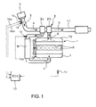
- Fig. 1 shows the embodiment of the invention.
- reference numeral 1 denotes an engine with a turbocharger 2 having a compressor 2a to which fed is intake air 4 from an air cleaner 3 through an intake pipe 5.
- the intake air 4 thus pressurized in the compressor 2a is fed to an intercooler 6 where it is cooled.
- the cooled intake air 4 from the intercooler 6 is further guided to an intake manifold 7 and distributed into each of cylinders 8 in the engine 1.
- Exhaust gas 9 discharged from each of the cylinders 8 in the engine 1 is fed via an exhaust manifold 10 to a turbine 2b of the turbocharger 2.
- the exhaust gas 9 thus having driven the turbine 2b is discharged through an exhaust pipe 11 to outside of the vehicle.
- an atmospheric pressure sensor 13 (first pressure sensor) for detecting of an atmospheric pressure as an entry pressure of a compressor 2a.
- a boost pressure sensor 14 for detection of an exit pressure of the compressor 2a.
- an intake flow rate sensor 15 air flow meter
- an intake temperature sensor 16 for detection of an entry temperature of the intake air 4.
- the intake flow rate and temperature sensors 15 and 16 are separately disclosed. However, actually a temperature of the intake air 4 (fresh air) is required for determining a mass flow rate of the intake air 4, so that usually the intake temperature sensor 16 is built in the intake flow rate sensor 15.
- Detection signals 13a, 14a, 15a and 16a from the atmospheric pressure sensor 13, the boost pressure sensor 14, the intake flow rate sensor 15 and the intake temperature sensor 16 are inputted to a controller 12 (arithmetic device) constituting an engine control computer (ECU: Electronic Control Unit).
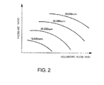
- Digitally stored in the controller 12 is an operating characteristic diagram (see Fig. 2 ) for equal rotational frequency lines of the compressor 2a in the turbocharger 2 represented by a volumetric flow rate of the intake air 4 and a pressure ratio under a standard environmental condition where an entry pressure of the compressor 2a and an entry temperature of the intake air 4 are predetermined standard values.
- the single turbocharger 2 is used, the standard environmental condition being such that the entry pressure of the compressor 2 is 1 atm (standard atmospheric pressure) corresponding to an atmospheric pressure and the entry temperature of intake air 4 is 293K (20°C).
- atmospheric and boost pressure sensors 13 and 14 are used as first and second pressure sensors for detection of entry and exit pressures of the compressor 2a, respectively, and the intake temperature sensor 16 built in the intake flow rate sensor 15 is used as an intake temperature sensor for detecting an entry temperature of the intake air 4.
- each of the second and further turbochargers 2 must have additional first and second pressure sensors for detection of entry and exit pressures of its compressor 2a as well as an additional intake temperature sensor for detection of entry temperature of the intake air 4.
- additional first and second pressure sensors for detection of entry and exit pressures of its compressor 2a
- an additional intake temperature sensor for detection of entry temperature of the intake air 4.
- Fig. 3 shows, in flowchart, the proceeding for determining the rotational frequency of turbocharger 2, using the controller 12.
- controller 12 calculated firstly in step S1 on the basis of the entry pressure (atmospheric pressure) and the exit pressure (boost pressure) of the compressor 2a detected by the atmospheric and boost pressure sensors 13 and 14, respectively, is the pressure ratio of the compressor 2a according to the following equation (1).
- pressure ratio ⁇ c exit pressure / entry pressure
- step S2 calculated in step S2 using a gas state equation on the basis of the mass flow rate and the entry temperature of the intake air 4 detected by the intake flow rate and temperature sensors 15 and 16, respectively, and the entry pressure is the volumetric flow rate of the intake air 4 under an environmental condition at a time of detection.
- step S3 the calculated volumetric flow rate is corrected into a corrected volumetric flow rate under the standard environmental condition through multiplication by a corrective coefficient based on the entry temperature of the intake air 4.
- the steps S2 and S3 may be conducted concurrently according to the following equation (2).
- the gas state equation P denotes pressure of the gas; V, volumetric flow rate of the gas; g, mass flow rate of the gas; R, gas constant; and T, temperature of the gas
- P denotes pressure of the gas
- V volumetric flow rate of the gas
- g mass flow rate of the gas
- R gas constant
- T temperature of the gas
- used as the corrective coefficient is a square root of a quotient obtained by dividing the entry temperature 293K (absolute temperature) at the standard environmental condition with the entry temperature T (absolute temperature detected by the intake temperature sensor 16) at the time of detection.
- a rotational frequency N t293 of the compressor 2a under the standard environmental condition. Further, the read-out rotational frequency N t293 is corrected in a next step S5 into an actual rotational frequency N t of the compressor 2a through multiplication by the corrective coefficient based on the entry temperature T of the intake air 4. The corrected value N t is determined in a next step S6 as the rotational frequency of the turbocharger 2.
- step S4 the operating characteristic diagram used in step S4 is digitally stored as function program in the controller 12.
- a rotational frequency N t293 is calculated through the function program.
- the corrective coefficient used in step S5 is the square root of the quotient obtained by dividing the entry temperature T (absolute temperature detected by the intake temperature sensor 16) at the time of detection with the entry temperature 293K (absolute temperature) under the standard environmental condition. More specifically, the rotational frequency N t293 is corrected into the actual rotational frequency N t according to the following equation (3). The multiplication of such corrective coefficient enables correction into the actual rotational frequency of the compressor 2a, which is due to the gas similarity rule.
- rotational frequency N t rotational frequency N t ⁇ 293 ⁇ ⁇ entry temperature T / 293
- the compressor 2a in general has a characteristic that when the pressure ratio (ratio of entry and exit pressures) of the compressor rotated at a rotational frequency is determined, the volumetric flow rate of the intake air 4 in the compressor 2a is unambiguously determined, so that experimentally obtained equal rotational frequency lines can be plotted on the graph with the ordinate representing a pressure ratio and the abscissa representing a volumetric flow rate of the intake air 4.
- a rotational frequency can be read out from the pressure ratio and the volumetric flow rate.
- the above-mentioned operating characteristic diagram comes into effect under an environmental condition with a single entry temperature and a single entry pressure; even if the intake air 4 has the same mass flow rate, the volumetric flow rate may become greater due to expansion provided that the entry temperature becomes higher or the entry pressure becomes lower.
- the rotational frequency cannot be read out from the operating characteristic diagram under the standard environmental condition stored in the controller 12 since the calculated volumetric flow rate is not standardized.
- the calculated volumetric flow rate is corrected into a corrected volumetric flow rate under the standard environmental condition through multiplication by the corrective coefficient on the basis of the entry temperature of the intake air 4.
- the rotational frequency of the compressor 2a under the standard environmental condition can be read out in light of the operating characteristic diagram.
- the rotational frequency read out in light of the operating characteristic diagram is a rotational frequency of the compressor 2a under the standard environmental condition and is different from an actual rotational frequency.
- the read-out rotational frequency is converted into the actual rotational frequency of the compressor 2a through multiplication by the corrective coefficient based on the entry temperature of the intake air 4, the converted value being determined as the rotational frequency of the turbocharger 2.
- the controller 12 is adapted to determine overrun of the turbocharger 2 when the rotational frequency of the turbocharger 2 is detected to exceed a predetermined threshold over a predetermined time period. This makes it possible to monitor the rotational frequency of the turbocharger 2 so as to determine the overrun and prevent beforehand the turbocharger 2 from being broken.
- the rotational frequency of the turbocharger 2 can be determined by the physical calculations on the basis of the entry and exit pressures of the compressor 2a and the mass flow rate and the entry temperature of the intake air 4.
- the rotational frequency thereof can be monitored to prevent the turbocharger 2 from being broken due to overrun.
- substantial reduction in cost may be attained by omitting the rotation sensor.
- turbo rotational frequency detection device is not limited to the above embodiment and that various changes and modifications may be made without departing from the scope of the invention.
Landscapes
- Engineering & Computer Science (AREA)
- Chemical & Material Sciences (AREA)
- Combustion & Propulsion (AREA)
- Mechanical Engineering (AREA)
- General Engineering & Computer Science (AREA)
- Physics & Mathematics (AREA)
- General Physics & Mathematics (AREA)
- Supercharger (AREA)
Abstract
Description
- The present invention relates to a turbo rotational frequency detection device.
- In recent engine designing, a downsizing concept shifted from a conventional concept with a high regard to top performance is becoming mainstream. In progress is changeover to supercharged engines in which engine displacement and a number of cylinders are reduced by supercharging with a turbocharger to obtain an output and a torque equivalent to those of natural intake engines with a size larger than the supercharged ones.
- For example, in diesel engines, V-twelve and -eight engines used to be prevailing in particular with respect to commercial vehicles (trucks). Now, supercharged straight-six and -four engines are becoming mainstream owing to the downsizing concept.
- In association with such downsizing concept being becoming main stream, further compactification in size of turbochargers has been demanded, which makes it difficult to arrange a rotation sensor at a bearing portion between a turbine and a compressor of a turbocharger as ever.
- Specifically, in the conventional rotation sensor, a disc with a circumferential notch is integrally fitted over a rotary shaft interconnecting the turbine and the compressor of the turbocharger. Arranged adjacent to the disc is a non-contact sensor which grasps passing of the notch of the disc as, for example, change in a magnetic field so that the passing of the notch of the disc is detected and counted by the sensor, whereby a rotational frequency of the turbocharger can be monitored. However, cases increase where no spatial room is left between the turbine and the compressor due to pipings of, for example, cooling water and lubrication oil so that the disc and the non-contact sensor cannot be physically arranged.
- There exists, for example, the following
Patent Literature 1 as conventional art document pertinent to the invention. - [Patent Literature 1]
JP 2006-057526A - In a turbocharger where no rotation sensor can be arranged to monitor a rotational frequency of the turbocharger, overrun with excessive rotational velocity beyond a limit velocity cannot be detected so that the turbocharger may overrun into breakage. Especially in usage at highland or the like where overrun tends to occur due to lowered air density resulting from barometric depression, there may be cases where an output of an engine has to be lowered to suppress the rotational frequency.
- The invention was made in view of the above and has its object to provide a turbo rotational frequency detection device capable of determining a rotational frequency of a turbocharger without a rotation sensor.
- The invention is directed to a turbo rotational frequency detection device comprising first and second pressure sensors for detecting entry and exit pressures of a compressor, respectively, intake flow rate and temperature sensors for detecting a mass flow rate and an entry temperature of intake air, respectively, and an arithmetic device for digitally storing an operating characteristic diagram showing equal rotational frequency lines of the compressor in a turbocharger in terms of a volumetric flow rate of the intake air and a pressure ratio under a standard environmental condition where the entry pressure of the compressor and the entry temperature of the intake air are predetermined standard values,
said arithmetic device being adapted to calculate a pressure ratio of said compressor on the basis of the entry and exit pressures of the compressor detected by the first and second pressure sensors, respectively, and calculate a volumetric flow rate of the intake air under an environmental condition at a time of detection using a gas state equation on the basis of the mass flow rate and the entry temperature of the intake air detected by the intake flow rate and temperature sensors, respectively, and said entry pressure of the compressor, correct the calculated volumetric flow rate into a volumetric flow rate under said standard environmental condition through multiplication by a corrective coefficient based on said entry temperature, read out a rotational frequency under the standard environmental condition on the basis of the corrected volumetric flow rate and said calculated pressure ratio and in light of said operating characteristic diagram, correct the read-out rotational frequency into an actual rotational frequency of the compressor through multiplication by the corrective coefficient based on the entry temperature of the intake air and determine the actual rotational frequency as a rotational frequency of the turbocharger. - Specifically, a compressor in general has a characteristic that if a pressure ratio (ratio of entry and exit pressures) of the compressor rotated at a rotational frequency is determined, a volumetric flow rate of intake air in the compressor is unambiguously determined, so that experimentally obtained equal rotational frequency lines can be plotted on a graph with an ordinate representing a pressure ratio and an abscissa representing a volumetric flow rate of the intake air. On the basis of an operating characteristic diagram (compressor map) in the form of such graph, a rotational frequency can be read out from the pressure ratio and the volumetric flow rate.
- However, the above-mentioned operating characteristic diagram comes into effect under an environmental condition with a single entry temperature and a single entry pressure; even if the intake air has the same mass flow rate, the volumetric flow rate may become greater due to expansion provided that the entry temperature becomes higher or the entry pressure becomes lower. Thus, it is necessary to determine a standard environmental condition where an entry pressure of the compressor and an entry temperature of the intake air have predetermined standard values and use as a standard a volumetric flow rate under the standard environmental condition.
- Thus, even if the pressure ratio of the compressor is calculated on the basis of the entry and exit pressures of the compressor detected by first and second pressure sensors, respectively, and the volumetric flow rate of the intake air under an environmental condition at a time of detection is calculated using a gas state equation on the basis of the mass flow rate and the entry temperature of the intake air detected by intake flow rate and temperature sensors, respectively, and the entry pressure of the compressor, a rotational frequency cannot be read out from the operating characteristic diagram stored in an arithmetic device since the calculated volumetric flow rate is not standardized.
- Then, the calculated volumetric flow rate is corrected into a corrected volumetric flow rate under the standard environmental condition through multiplication by the corrective coefficient on the basis of the entry temperature of the intake air. On the basis of the corrected volumetric flow rate and the calculated pressure ratio, a rotational frequency of the compressor under the standard environmental condition can be read out in light of the operating characteristic diagram.
- In the correction of the calculated volumetric flow rate into the corrected volumetric flow rate under the standard environmental condition through multiplication by the corrective coefficient based on the entry temperature of the intake air, usable as the corrective coefficient is a square root of a quotient obtained through division of the entry temperature (absolute temperature detected by the intake temperature sensor) at the time of detection by the entry temperature (absolute temperature) under the standard environmental condition. The multiplication by such corrective coefficient enables the correction into the volumetric flow rate under the standard environmental condition, which is due to gas similarity rule.
- However, the rotational frequency read out in light of the operating characteristic diagram is the rotational frequency of the compressor under the standard environmental condition and is different from an actual rotational frequency. Thus, the read-out rotational frequency is converted into the actual rotational frequency of the compressor through multiplication by the corrective coefficient based on the entry temperature of the intake air, the converted value being determined as the rotational frequency of the turbocharger.
- In the conversion of the value read out from the operating characteristic diagram into the actual rotational frequency of the compressor through multiplication by the corrective coefficient based on the entry temperature of the intake air, usable as the corrective coefficient is a square root of a quotient obtained through division of the entry temperature (absolute temperature detected by the intake temperature sensor) at the time of detection by the entry temperature (absolute temperature) under the standard environmental condition. The multiplication by such corrective coefficient enables the correction into the actual volumetric flow rate, which is due to gas similarity rule.
- Further, it is preferable in the invention that the arithmetic device is adapted to determine overrun of the turbocharger when the rotational frequency of the turbocharger is detected to exceed a predetermined threshold over a predetermined time period or more. This makes it possible to monitor the rotational frequency of the turbocharger so as to determine the overrun and prevent beforehand the turbocharger from being broken.
- Excellent effects can be obtained according to the above-mentioned turbo rotational frequency detection device of the invention. Without a rotation sensor at a bearing portion between a turbine and a compressor of a turbocharger, a rotational frequency of the turbocharger can be determined by physical calculations on the basis of entry and exit pressures of the compressor and mass flow rate and entry temperature of intake air. Thus, even in the turbocharger with no spatial room for arrangement of the rotation sensor, the rotational frequency thereof can be monitored to prevent the turbocharger from being broken due to overrun. Moreover, even in a turbocharge with spatial room for arrangement of the rotation sensor, substantial reduction in cost may be attained by omitting the rotation sensor.
-
-
Fig. 1 is a schematic view showing an embodiment of the invention; -
Fig. 2 is an operating characteristic diagram digitally stored in the controller inFig. 1 ; and -
Fig. 3 is a flowchart of a proceeding for determining a rotational frequency of a turbocharger inFig. 1 . - An embodiment of the invention will be described in conjunction with the drawings.
-
Fig. 1 shows the embodiment of the invention. InFig. 1 ,reference numeral 1 denotes an engine with aturbocharger 2 having acompressor 2a to which fed is intakeair 4 from anair cleaner 3 through anintake pipe 5. Theintake air 4 thus pressurized in thecompressor 2a is fed to an intercooler 6 where it is cooled. The cooledintake air 4 from the intercooler 6 is further guided to anintake manifold 7 and distributed into each ofcylinders 8 in theengine 1. -
Exhaust gas 9 discharged from each of thecylinders 8 in theengine 1 is fed via anexhaust manifold 10 to aturbine 2b of theturbocharger 2. Theexhaust gas 9 thus having driven theturbine 2b is discharged through anexhaust pipe 11 to outside of the vehicle. - Further, arranged at an appropriate site in an engine compartment less affected by aerodynamic drag is an atmospheric pressure sensor 13 (first pressure sensor) for detecting of an atmospheric pressure as an entry pressure of a
compressor 2a. Arranged in anintake pipe 5 between thecompressor 2a and the intercooler 6 is aboost pressure sensor 14 for detection of an exit pressure of thecompressor 2a. Arranged in theintake pipe 5 upstream of thecompressor 2a at a position adjacent to theair cleaner 3 are an intake flow rate sensor 15 (air flow meter) for detection of a mass flow rate of theintake air 4 and anintake temperature sensor 16 for detection of an entry temperature of theintake air 4. - Here, for convenience of explanation, the intake flow rate and
temperature sensors intake air 4, so that usually theintake temperature sensor 16 is built in the intakeflow rate sensor 15. - Detection signals 13a, 14a, 15a and 16a from the
atmospheric pressure sensor 13, theboost pressure sensor 14, the intakeflow rate sensor 15 and theintake temperature sensor 16 are inputted to a controller 12 (arithmetic device) constituting an engine control computer (ECU: Electronic Control Unit). Digitally stored in thecontroller 12 is an operating characteristic diagram (seeFig. 2 ) for equal rotational frequency lines of thecompressor 2a in theturbocharger 2 represented by a volumetric flow rate of theintake air 4 and a pressure ratio under a standard environmental condition where an entry pressure of thecompressor 2a and an entry temperature of theintake air 4 are predetermined standard values. - Illustrated is a case where the
single turbocharger 2 is used, the standard environmental condition being such that the entry pressure of thecompressor 2 is 1 atm (standard atmospheric pressure) corresponding to an atmospheric pressure and the entry temperature ofintake air 4 is 293K (20°C). As usual existing facilities, atmospheric andboost pressure sensors compressor 2a, respectively, and theintake temperature sensor 16 built in the intakeflow rate sensor 15 is used as an intake temperature sensor for detecting an entry temperature of theintake air 4. - However, in a multi-stage supercharging system having a plurality stages of
turbochargers 2, each of the second andfurther turbochargers 2 must have additional first and second pressure sensors for detection of entry and exit pressures of itscompressor 2a as well as an additional intake temperature sensor for detection of entry temperature of theintake air 4. However, there is no specific difference between single- and multi-stage supercharging systems with respect to a below-mentioned proceeding for determining a rotational frequency ofturbocharger 2, using thecontroller 12. -
Fig. 3 shows, in flowchart, the proceeding for determining the rotational frequency ofturbocharger 2, using thecontroller 12. In thecontroller 12, calculated firstly in step S1 on the basis of the entry pressure (atmospheric pressure) and the exit pressure (boost pressure) of thecompressor 2a detected by the atmospheric and boostpressure sensors compressor 2a according to the following equation (1).
- In parallel with step S1, calculated in step S2 using a gas state equation on the basis of the mass flow rate and the entry temperature of the
intake air 4 detected by the intake flow rate andtemperature sensors intake air 4 under an environmental condition at a time of detection. In a next step S3, the calculated volumetric flow rate is corrected into a corrected volumetric flow rate under the standard environmental condition through multiplication by a corrective coefficient based on the entry temperature of theintake air 4. - The steps S2 and S3 may be conducted concurrently according to the following equation (2). In the equation (2), the gas state equation (PV = gRT where P denotes pressure of the gas; V, volumetric flow rate of the gas; g, mass flow rate of the gas; R, gas constant; and T, temperature of the gas) is converted into a shape for obtaining the volumetric flow rate V and multiplied by the corrective coefficient based on the entry temperature T of the
intake air 4. Here, used as the corrective coefficient is a square root of a quotient obtained by dividing the entry temperature 293K (absolute temperature) at the standard environmental condition with the entry temperature T (absolute temperature detected by the intake temperature sensor 16) at the time of detection. The equation is simplified by taking the temperature T used in the gas state equation into the root in the corrective coefficient equation. The multiplication by such corrective coefficient enables the correction into volumetric flow rate under the standard environmental condition, which is due to gas similarity rule.
- Then, read out in a next step S4 on the basis of the corrected value Qa293 of the volumetric flow rate and the calculated pressure ratio πc (obtained in step S1) and in light of the operating characteristic diagram (see
Fig. 2 ) is a rotational frequency Nt293 of thecompressor 2a under the standard environmental condition. Further, the read-out rotational frequency Nt293 is corrected in a next step S5 into an actual rotational frequency Nt of thecompressor 2a through multiplication by the corrective coefficient based on the entry temperature T of theintake air 4. The corrected value Nt is determined in a next step S6 as the rotational frequency of theturbocharger 2. - Here, the operating characteristic diagram used in step S4 is digitally stored as function program in the
controller 12. By inputting the corrected value Qa293 of the volumetric flow rate and the calculated pressure ratio πc, a rotational frequency Nt293 is calculated through the function program. - Further, the corrective coefficient used in step S5 is the square root of the quotient obtained by dividing the entry temperature T (absolute temperature detected by the intake temperature sensor 16) at the time of detection with the entry temperature 293K (absolute temperature) under the standard environmental condition. More specifically, the rotational frequency Nt293 is corrected into the actual rotational frequency Nt according to the following equation (3). The multiplication of such corrective coefficient enables correction into the actual rotational frequency of the
compressor 2a, which is due to the gas similarity rule.
- Such proceeding for determining the rotational frequency of the
turbocharger 2 in thecontroller 12 will be amplified. Thecompressor 2a in general has a characteristic that when the pressure ratio (ratio of entry and exit pressures) of the compressor rotated at a rotational frequency is determined, the volumetric flow rate of theintake air 4 in thecompressor 2a is unambiguously determined, so that experimentally obtained equal rotational frequency lines can be plotted on the graph with the ordinate representing a pressure ratio and the abscissa representing a volumetric flow rate of theintake air 4. On the basis of the operating characteristic diagram (compressor map: seeFig. 2 ) in the form of such graph, a rotational frequency can be read out from the pressure ratio and the volumetric flow rate. - However, the above-mentioned operating characteristic diagram comes into effect under an environmental condition with a single entry temperature and a single entry pressure; even if the
intake air 4 has the same mass flow rate, the volumetric flow rate may become greater due to expansion provided that the entry temperature becomes higher or the entry pressure becomes lower. Thus, it is necessary to determine a standard environmental condition where the entry pressure of thecompressor 2a and the entry temperature of theintake air 4 have predetermined standard values and use as a standard a volumetric flow rate under the standard environmental condition. - Thus, even if the pressure ratio of the
compressor 2a is calculated on the basis of entry and exit pressures of thecompressor 2a detected by the atmospheric and boostpressure sensors intake air 4 under the environmental condition at the time of detection is calculated using the gas state equation on the basis of the mass flow rate and the entry temperature of theintake air 4 detected by intake flow rate andtemperature sensors controller 12 since the calculated volumetric flow rate is not standardized. - Then, the calculated volumetric flow rate is corrected into a corrected volumetric flow rate under the standard environmental condition through multiplication by the corrective coefficient on the basis of the entry temperature of the
intake air 4. On the basis of the corrected volumetric flow rate and the calculated pressure ratio, the rotational frequency of thecompressor 2a under the standard environmental condition can be read out in light of the operating characteristic diagram. - However, the rotational frequency read out in light of the operating characteristic diagram is a rotational frequency of the
compressor 2a under the standard environmental condition and is different from an actual rotational frequency. Thus, the read-out rotational frequency is converted into the actual rotational frequency of thecompressor 2a through multiplication by the corrective coefficient based on the entry temperature of theintake air 4, the converted value being determined as the rotational frequency of theturbocharger 2. - In this case, it is preferable that the
controller 12 is adapted to determine overrun of theturbocharger 2 when the rotational frequency of theturbocharger 2 is detected to exceed a predetermined threshold over a predetermined time period. This makes it possible to monitor the rotational frequency of theturbocharger 2 so as to determine the overrun and prevent beforehand theturbocharger 2 from being broken. - Thus, according to the above-mentioned embodiment, without a rotation sensor at the bearing portion between the
turbine 2b and thecompressor 2a of theturbocharger 2, the rotational frequency of theturbocharger 2 can be determined by the physical calculations on the basis of the entry and exit pressures of thecompressor 2a and the mass flow rate and the entry temperature of theintake air 4. Thus, even in theturbocharger 2 with no spatial room for arrangement of the rotation sensor, the rotational frequency thereof can be monitored to prevent theturbocharger 2 from being broken due to overrun. Moreover, even in theturbocharger 2 with spatial room for arrangement of the rotation sensor, substantial reduction in cost may be attained by omitting the rotation sensor. - It is to be understood that a turbo rotational frequency detection device according to the invention is not limited to the above embodiment and that various changes and modifications may be made without departing from the scope of the invention.
-
- 2
- turbocharger
- 2a
- compressor
- 4
- intake air
- 12
- controller (arithmetic device)
- 13
- atmospheric pressure sensor (first pressure sensor)
- 14
- boost pressure sensor (second pressure sensor)
- 15
- intake flow rate sensor
- 16
- intake temperature sensor
Claims (2)
- A turbo rotational frequency detection device comprising first and second pressure sensors for detecting entry and exit pressures of a compressor, respectively, intake flow rate and temperature sensors for detecting a mass flow rate and an entry temperature of intake air, respectively, and an arithmetic device for digitally storing an operating characteristic diagram showing equal rotational frequency lines of the compressor in a turbocharger in terms of a volumetric flow rate of the intake air and a pressure ratio under a standard environmental condition where the entry pressure of the compressor and the entry temperature of the intake air are predetermined standard values,
said arithmetic device being adapted to calculate a pressure ratio of said compressor on the basis of the entry and exit pressures of the compressor detected by the first and second pressure sensors, respectively, and calculate a volumetric flow rate of the intake air under an environmental condition at a time of detection using a gas state equation on the basis of the mass flow rate and the entry temperature of the intake air detected by the intake flow rate and temperature sensors, respectively, and said entry pressure of the compressor, correct the calculated volumetric flow rate into a volumetric flow rate under said standard environmental condition through multiplication by a corrective coefficient based on said entry temperature, read out a rotational frequency under the standard environmental condition on the basis of the corrected volumetric flow rate and said calculated pressure ratio and in light of said operating characteristic diagram, correct the read-out rotational frequency into an actual rotational frequency of the compressor through multiplication by the corrective coefficient based on the entry temperature of the intake air and determine the actual rotational frequency as a rotational frequency of the turbocharger. - The turbo rotational frequency detection device as claimed in claim 1 wherein the arithmetic device is adapted to determine overrun of the turbocharger when the rotational frequency of the turbocharger is detected to exceed a predetermined threshold over a predetermined time period or more.
Applications Claiming Priority (2)
| Application Number | Priority Date | Filing Date | Title |
|---|---|---|---|
| JP2012143657A JP6032966B2 (en) | 2012-06-27 | 2012-06-27 | Turbo speed detector |
| PCT/JP2013/003928 WO2014002464A1 (en) | 2012-06-27 | 2013-06-24 | Turbo rotational frequency detection device |
Publications (2)
| Publication Number | Publication Date |
|---|---|
| EP2868895A1 true EP2868895A1 (en) | 2015-05-06 |
| EP2868895A4 EP2868895A4 (en) | 2016-03-02 |
Family
ID=49782657
Family Applications (1)
| Application Number | Title | Priority Date | Filing Date |
|---|---|---|---|
| EP13808441.3A Withdrawn EP2868895A4 (en) | 2012-06-27 | 2013-06-24 | Turbo rotational frequency detection device |
Country Status (5)
| Country | Link |
|---|---|
| US (1) | US9804059B2 (en) |
| EP (1) | EP2868895A4 (en) |
| JP (1) | JP6032966B2 (en) |
| CN (1) | CN104379901B (en) |
| WO (1) | WO2014002464A1 (en) |
Families Citing this family (16)
| Publication number | Priority date | Publication date | Assignee | Title |
|---|---|---|---|---|
| FR3000136B1 (en) * | 2012-12-20 | 2015-01-16 | Renault Sa | METHOD FOR DIAGNOSING A SUPERCHARGED ENGINE AND ENGINE THEREFOR |
| CN104833815A (en) * | 2015-03-04 | 2015-08-12 | 诸城福田汽车科技开发有限公司 | Method, apparatus and equipment for measuring rotating speed of engine |
| WO2016177413A1 (en) * | 2015-05-06 | 2016-11-10 | Volvo Truck Corporation | A method for modeling a compressor speed |
| JP6550943B2 (en) * | 2015-06-10 | 2019-07-31 | いすゞ自動車株式会社 | Controller of variable displacement turbocharger |
| US11053875B2 (en) | 2016-02-10 | 2021-07-06 | Garrett Transportation I Inc. | System and method for estimating turbo speed of an engine |
| US10273874B2 (en) * | 2016-04-15 | 2019-04-30 | Ford Global Technologies, Llc | Method and system for compressor outlet temperature regulation |
| WO2018219449A1 (en) * | 2017-05-31 | 2018-12-06 | Volvo Truck Corporation | A method and vehicle system using such method |
| US11149665B2 (en) * | 2017-05-31 | 2021-10-19 | Volvo Truck Corporation | Method and system for controlling engine derating |
| KR101982666B1 (en) * | 2017-10-18 | 2019-05-29 | 디에스글로벌(주) | Photo printer |
| CN109162808A (en) * | 2018-08-31 | 2019-01-08 | 安徽理工大学 | A kind of device and its measurement method measuring turbo charger speed |
| JP6824376B2 (en) * | 2019-12-25 | 2021-02-03 | ボルボトラックコーポレーション | How to model compressor speed |
| RU2769291C2 (en) * | 2020-08-26 | 2022-03-30 | Федеральное государственное казённое военное образовательное учреждение высшего образования "Военная академия материально-технического обеспечения имени генерала армии А.В. Хрулева" Министерства обороны Российской Федерации | Method for express diagnostics of the turbocharger of a diesel engine |
| CN113530666B (en) * | 2021-07-12 | 2022-06-21 | 安徽江淮汽车集团股份有限公司 | Method for regulating and controlling rotating speed of turbocharger |
| CN113310536B (en) * | 2021-07-29 | 2022-01-07 | 中国航发上海商用航空发动机制造有限责任公司 | Method for measuring inlet flow of compressor in engine whole machine test |
| CN113482764B (en) * | 2021-07-30 | 2022-05-20 | 广西玉柴机器股份有限公司 | Method for diagnosing boost pressure fault of controllable supercharger |
| CN116201632B (en) * | 2022-03-17 | 2025-06-24 | 潍柴动力股份有限公司 | A method and device for monitoring supercharger speed, electronic equipment, and storage medium |
Family Cites Families (13)
| Publication number | Priority date | Publication date | Assignee | Title |
|---|---|---|---|---|
| JPH0510149A (en) * | 1991-07-01 | 1993-01-19 | Mazda Motor Corp | Control device for engine with supercharger |
| JP3985375B2 (en) * | 1999-01-14 | 2007-10-03 | 日産自動車株式会社 | Engine intake control device |
| US6298718B1 (en) | 2000-03-08 | 2001-10-09 | Cummins Engine Company, Inc. | Turbocharger compressor diagnostic system |
| US6539714B1 (en) * | 2002-03-19 | 2003-04-01 | Cummins, Inc. | System for estimating turbocharger rotational speed |
| JP4356072B2 (en) * | 2004-07-09 | 2009-11-04 | 株式会社デンソー | Control device for internal combustion engine equipped with turbocharger |
| JP2006029279A (en) * | 2004-07-21 | 2006-02-02 | Denso Corp | Control device for internal combustion engine |
| JP2006057526A (en) | 2004-08-19 | 2006-03-02 | Denso Corp | Fault diagnosis device for internal combustion engine |
| JP2008008202A (en) * | 2006-06-29 | 2008-01-17 | Hino Motors Ltd | Turbine protection device |
| JP2009057944A (en) * | 2007-09-03 | 2009-03-19 | Toyota Motor Corp | Supercharging control device for internal combustion engine |
| JP2009180162A (en) * | 2008-01-31 | 2009-08-13 | Nissan Motor Co Ltd | Turbocharger control device for internal combustion engine |
| CN102575577B (en) * | 2010-02-09 | 2014-08-20 | 三菱重工业株式会社 | Control device for engine with turbocharger |
| IT1401826B1 (en) * | 2010-09-27 | 2013-08-28 | Magneti Marelli Spa | METHOD OF CHECKING THE SPEED OF AN INTERNAL COMBUSTION MOTOR OVER-POWERED BY A TURBOCHARGER |
| JP5719257B2 (en) * | 2011-09-02 | 2015-05-13 | ダイムラー・アクチェンゲゼルシャフトDaimler AG | Supercharger control device |
-
2012
- 2012-06-27 JP JP2012143657A patent/JP6032966B2/en active Active
-
2013
- 2013-06-24 WO PCT/JP2013/003928 patent/WO2014002464A1/en not_active Ceased
- 2013-06-24 CN CN201380033381.7A patent/CN104379901B/en not_active Expired - Fee Related
- 2013-06-24 US US14/405,030 patent/US9804059B2/en not_active Expired - Fee Related
- 2013-06-24 EP EP13808441.3A patent/EP2868895A4/en not_active Withdrawn
Also Published As
| Publication number | Publication date |
|---|---|
| US9804059B2 (en) | 2017-10-31 |
| EP2868895A4 (en) | 2016-03-02 |
| JP2014005811A (en) | 2014-01-16 |
| WO2014002464A1 (en) | 2014-01-03 |
| JP6032966B2 (en) | 2016-11-30 |
| US20150143882A1 (en) | 2015-05-28 |
| CN104379901A (en) | 2015-02-25 |
| CN104379901B (en) | 2017-03-08 |
Similar Documents
| Publication | Publication Date | Title |
|---|---|---|
| US9804059B2 (en) | Turbo rotational frequency detection device | |
| US9010180B2 (en) | Method and observer for determining the exhaust manifold temperature in a turbocharged engine | |
| US7937996B2 (en) | Turbo speed sensor diagnostic for turbocharged engines | |
| US8201442B2 (en) | System and method for estimating EGR mass flow rates | |
| US8307645B2 (en) | Apparatus and method for avoidance of turbocharger surge on locomotive diesel engines | |
| US20160003180A1 (en) | System for estimating exhaust manifold temperature | |
| EP2444629A1 (en) | Control device for engine with turbocharger | |
| US8353201B2 (en) | Intake air temperature rationality diagnostic | |
| US7593808B2 (en) | Apparatus and method for engine performance evaluation | |
| US20210293193A1 (en) | System and method for estimating turbo speed of an engine | |
| US9206768B2 (en) | Method and apparatus for determining abnormality in exhaust gas recirculation amount | |
| EP2541015B1 (en) | Control device for internal combustion engine | |
| US8285496B2 (en) | Method and device for providing air mass flow information in a supercharged internal combustion engine | |
| CN102678330A (en) | Diagnostic method for pressure sensors in turbocharging system | |
| US20180313356A1 (en) | Method for compressor surge detection to enable model base air estimation | |
| US7254477B1 (en) | Apparatus and method for engine performance evaluation | |
| JP2007205339A (en) | Turbocharger state quantity estimation device | |
| EP3064756A1 (en) | Method for estimating pressure loss of air cleaner and device for estimating pressure loss of air cleaner | |
| US12372040B2 (en) | Internal combustion engine system | |
| CN118979824B (en) | A turbocharger hardware protection method based on dynamic density limitation | |
| JP6453121B2 (en) | Control device for variable capacity turbocharger | |
| JP5589892B2 (en) | Centrifugal compressor control device | |
| EP3064922A1 (en) | Diagnosis device and diagnosis method for turbocharger |
Legal Events
| Date | Code | Title | Description |
|---|---|---|---|
| PUAI | Public reference made under article 153(3) epc to a published international application that has entered the european phase |
Free format text: ORIGINAL CODE: 0009012 |
|
| 17P | Request for examination filed |
Effective date: 20141217 |
|
| AK | Designated contracting states |
Kind code of ref document: A1 Designated state(s): AL AT BE BG CH CY CZ DE DK EE ES FI FR GB GR HR HU IE IS IT LI LT LU LV MC MK MT NL NO PL PT RO RS SE SI SK SM TR |
|
| AX | Request for extension of the european patent |
Extension state: BA ME |
|
| DAX | Request for extension of the european patent (deleted) | ||
| RA4 | Supplementary search report drawn up and despatched (corrected) |
Effective date: 20160203 |
|
| RIC1 | Information provided on ipc code assigned before grant |
Ipc: F02B 39/16 20060101AFI20160128BHEP |
|
| 17Q | First examination report despatched |
Effective date: 20170330 |
|
| STAA | Information on the status of an ep patent application or granted ep patent |
Free format text: STATUS: THE APPLICATION IS DEEMED TO BE WITHDRAWN |
|
| 18D | Application deemed to be withdrawn |
Effective date: 20180609 |