EP2868869A1 - Gas turbine engine gap seal made of a sealing strip covered by a sealant / filler - Google Patents
Gas turbine engine gap seal made of a sealing strip covered by a sealant / filler Download PDFInfo
- Publication number
- EP2868869A1 EP2868869A1 EP20140185908 EP14185908A EP2868869A1 EP 2868869 A1 EP2868869 A1 EP 2868869A1 EP 20140185908 EP20140185908 EP 20140185908 EP 14185908 A EP14185908 A EP 14185908A EP 2868869 A1 EP2868869 A1 EP 2868869A1
- Authority
- EP
- European Patent Office
- Prior art keywords
- component
- sealing strip
- gap
- turbine engine
- gas turbine
- Prior art date
- Legal status (The legal status is an assumption and is not a legal conclusion. Google has not performed a legal analysis and makes no representation as to the accuracy of the status listed.)
- Granted
Links
Images





Classifications
-
- F—MECHANICAL ENGINEERING; LIGHTING; HEATING; WEAPONS; BLASTING
- F02—COMBUSTION ENGINES; HOT-GAS OR COMBUSTION-PRODUCT ENGINE PLANTS
- F02K—JET-PROPULSION PLANTS
- F02K1/00—Plants characterised by the form or arrangement of the jet pipe or nozzle; Jet pipes or nozzles peculiar thereto
- F02K1/78—Other construction of jet pipes
- F02K1/80—Couplings or connections
- F02K1/805—Sealing devices therefor, e.g. for movable parts of jet pipes or nozzle flaps
-
- B—PERFORMING OPERATIONS; TRANSPORTING
- B29—WORKING OF PLASTICS; WORKING OF SUBSTANCES IN A PLASTIC STATE IN GENERAL
- B29C—SHAPING OR JOINING OF PLASTICS; SHAPING OF MATERIAL IN A PLASTIC STATE, NOT OTHERWISE PROVIDED FOR; AFTER-TREATMENT OF THE SHAPED PRODUCTS, e.g. REPAIRING
- B29C65/00—Joining or sealing of preformed parts, e.g. welding of plastics materials; Apparatus therefor
- B29C65/48—Joining or sealing of preformed parts, e.g. welding of plastics materials; Apparatus therefor using adhesives, i.e. using supplementary joining material; solvent bonding
- B29C65/52—Joining or sealing of preformed parts, e.g. welding of plastics materials; Apparatus therefor using adhesives, i.e. using supplementary joining material; solvent bonding characterised by the way of applying the adhesive
- B29C65/54—Joining or sealing of preformed parts, e.g. welding of plastics materials; Apparatus therefor using adhesives, i.e. using supplementary joining material; solvent bonding characterised by the way of applying the adhesive between pre-assembled parts
- B29C65/542—Joining or sealing of preformed parts, e.g. welding of plastics materials; Apparatus therefor using adhesives, i.e. using supplementary joining material; solvent bonding characterised by the way of applying the adhesive between pre-assembled parts by injection
-
- F—MECHANICAL ENGINEERING; LIGHTING; HEATING; WEAPONS; BLASTING
- F01—MACHINES OR ENGINES IN GENERAL; ENGINE PLANTS IN GENERAL; STEAM ENGINES
- F01D—NON-POSITIVE DISPLACEMENT MACHINES OR ENGINES, e.g. STEAM TURBINES
- F01D11/00—Preventing or minimising internal leakage of working-fluid, e.g. between stages
- F01D11/001—Preventing or minimising internal leakage of working-fluid, e.g. between stages for sealing space between stator blade and rotor
-
- F—MECHANICAL ENGINEERING; LIGHTING; HEATING; WEAPONS; BLASTING
- F01—MACHINES OR ENGINES IN GENERAL; ENGINE PLANTS IN GENERAL; STEAM ENGINES
- F01D—NON-POSITIVE DISPLACEMENT MACHINES OR ENGINES, e.g. STEAM TURBINES
- F01D11/00—Preventing or minimising internal leakage of working-fluid, e.g. between stages
- F01D11/005—Sealing means between non relatively rotating elements
-
- F—MECHANICAL ENGINEERING; LIGHTING; HEATING; WEAPONS; BLASTING
- F02—COMBUSTION ENGINES; HOT-GAS OR COMBUSTION-PRODUCT ENGINE PLANTS
- F02K—JET-PROPULSION PLANTS
- F02K3/00—Plants including a gas turbine driving a compressor or a ducted fan
- F02K3/02—Plants including a gas turbine driving a compressor or a ducted fan in which part of the working fluid by-passes the turbine and combustion chamber
- F02K3/04—Plants including a gas turbine driving a compressor or a ducted fan in which part of the working fluid by-passes the turbine and combustion chamber the plant including ducted fans, i.e. fans with high volume, low pressure outputs, for augmenting the jet thrust, e.g. of double-flow type
-
- F—MECHANICAL ENGINEERING; LIGHTING; HEATING; WEAPONS; BLASTING
- F05—INDEXING SCHEMES RELATING TO ENGINES OR PUMPS IN VARIOUS SUBCLASSES OF CLASSES F01-F04
- F05D—INDEXING SCHEME FOR ASPECTS RELATING TO NON-POSITIVE-DISPLACEMENT MACHINES OR ENGINES, GAS-TURBINES OR JET-PROPULSION PLANTS
- F05D2300/00—Materials; Properties thereof
- F05D2300/40—Organic materials
- F05D2300/43—Synthetic polymers, e.g. plastics; Rubber
-
- F—MECHANICAL ENGINEERING; LIGHTING; HEATING; WEAPONS; BLASTING
- F05—INDEXING SCHEMES RELATING TO ENGINES OR PUMPS IN VARIOUS SUBCLASSES OF CLASSES F01-F04
- F05D—INDEXING SCHEME FOR ASPECTS RELATING TO NON-POSITIVE-DISPLACEMENT MACHINES OR ENGINES, GAS-TURBINES OR JET-PROPULSION PLANTS
- F05D2300/00—Materials; Properties thereof
- F05D2300/40—Organic materials
- F05D2300/43—Synthetic polymers, e.g. plastics; Rubber
- F05D2300/431—Rubber
-
- F—MECHANICAL ENGINEERING; LIGHTING; HEATING; WEAPONS; BLASTING
- F05—INDEXING SCHEMES RELATING TO ENGINES OR PUMPS IN VARIOUS SUBCLASSES OF CLASSES F01-F04
- F05D—INDEXING SCHEME FOR ASPECTS RELATING TO NON-POSITIVE-DISPLACEMENT MACHINES OR ENGINES, GAS-TURBINES OR JET-PROPULSION PLANTS
- F05D2300/00—Materials; Properties thereof
- F05D2300/60—Properties or characteristics given to material by treatment or manufacturing
- F05D2300/615—Filler
-
- Y—GENERAL TAGGING OF NEW TECHNOLOGICAL DEVELOPMENTS; GENERAL TAGGING OF CROSS-SECTIONAL TECHNOLOGIES SPANNING OVER SEVERAL SECTIONS OF THE IPC; TECHNICAL SUBJECTS COVERED BY FORMER USPC CROSS-REFERENCE ART COLLECTIONS [XRACs] AND DIGESTS
- Y02—TECHNOLOGIES OR APPLICATIONS FOR MITIGATION OR ADAPTATION AGAINST CLIMATE CHANGE
- Y02T—CLIMATE CHANGE MITIGATION TECHNOLOGIES RELATED TO TRANSPORTATION
- Y02T50/00—Aeronautics or air transport
- Y02T50/60—Efficient propulsion technologies, e.g. for aircraft
Definitions
- the present invention relates to a gas turbine engine.
- Turbofan gas turbine engines (which may be referred to simply as 'turbofans') are typically employed to power aircraft. Turbofans are particularly useful on commercial aircraft where fuel consumption is a primary concern.
- a turbofan gas turbine engine will comprise an axial fan driven by an engine core.
- the engine core is generally made up of one or more turbines which drive respective compressors via coaxial shafts.
- the fan is usually driven directly off an additional lower pressure turbine in the engine core.
- the fan draws air into the engine and the air is discharged through a bypass duct which provides a portion of the engine thrust.
- a series of outlet guide vanes are arranged and positioned between an inner and outer casing that define the bypass duct.
- a series of acoustic panels line the inner and outer casing.
- an infill panel is provided between each of the OGVs.
- the infill panel is generally a moulded component that includes acoustic chambers, and is typically bolted to the respective inner or outer casing.
- the distance of the gap can vary depending on a number of factors, including how tightly sections of the inner and/or outer case are connected (e.g. bolted) together. It is important that the gap between the infill panel and acoustic panel is sealed so as to create a smooth gas washed surface, but also to prevent air flow recirculating behind the acoustic panel and/or infill which could cause damage to the engine.
- the conventional method to fill the gap is to use a sealant such as polysulphide.
- FIG. 1 shows an arrangement of an infill and forward and rearward acoustic panels forming part of an outer casing assembly of the prior art.
- the casing assembly includes a fan case 1035 substantially coaxial with and connected to a mount ring 1039.
- the mount ring 1039 is substantially coaxial with and connected to a rear case 1041.
- Acoustic panels 1034A line the fan case and acoustic panels 1034B line the rear panel.
- the fan outlet guide vanes (OGVs) 1032 are connected to the mount ring, typically via bolts.
- An infill panel 1040 is positioned between each OGV to fill a void between the forward acoustic panel 1034A and the rearward acoustic panel 1034B.
- a gap 1044A is formed between the forward acoustic panel 1034A and the infill panel 1044. This gap is filled with polysulphide sealant 1048A.
- sealant is advantageous because an effective seal can be produced independently of the gap size.
- the use of sealant to fill the gap leads to increase weight of the engine, increased lead time due to the cure time for the sealant and increased cost.
- a further problem is that in-service-support may require the removal of a panel, which is time consuming because of the time taken to completely remove the sealant and then re-inject and cure the sealant.
- the present invention seeks to address one or more of the problems associated with connecting two components having a gas washed surface in gas turbine engines of the prior art.
- a first aspect of the invention provides a gas turbine engine having a fan and a bypass duct for discharging airflow from the fan to generate engine thrust, the bypass duct comprising:
- sealing strip and sealant effectively seals the gap between the first and second components and provides a smooth gas washed surface of the bypass duct.
- the provision of a sealing strip instead of only using sealant, as in the prior art, has several advantages including weight reduction, reduction in assembly time, and in some embodiments the sealing strip has been found to surprisingly have a damping effect.
- Use of the sealing strip is advantageous during servicing because it reduces the time required to remove and replace the seal.
- the first component may comprise a lip to limit movement of the sealing strip and/or sealant relative to the first component.
- the provision of a lip aids retention of the sealing strip and/or sealant in the gap between the first and second components.
- the second component may comprise a lip to limit movement of the sealing strip and/or sealant relative to the second component.
- the lip may be positioned to contact the sealant and form part of the gas washed surface of the first component. In such an arrangement the lip aids retention of both the sealing strip and the sealant.
- the lip may be positioned to be radially offset from the gas washed surface into the gap between the first and second components. Further alternatively, the lip may form part of the gas washed surface and the lip may extend radially into the gap between the first and second component and contact the sealing strip.
- the sealing strip may be made from a compressible material, e.g. a rubber, elastomer or compressible closed cell foam. Use of such materials has been found to be advantageous in terms of ease of location in the gap between the first and second components. Furthermore, such materials have been found to have a damping effect.
- a compressible material e.g. a rubber, elastomer or compressible closed cell foam.
- the sealing strip may form a hollow tube.
- the use of a hollow tube is further advantageous in reducing weight, easing location and when a compressible material (e.g. rubber, elastomer, compressible closed cell foam) is used, the hollow tube construction has been found to further improve damping.
- a sealing strip formed of a hollow tube and made from a compressible material has been found to provide an optimal solution because the flexibility of such a sealing strip ensures effective sealing of the gap between the first and second components, and also provides a damping function.
- the sealing strip may have a solid cross section.
- the sealing strip may have a cross section that is substantially rectangular with rounded ends or substantially circular.
- the sealing strip may have a cross section that is substantially rectangular or substantially oval.
- the sealing strip may be dimensioned so as to be in a compressed or near compressed state when positioned in the gap.
- the first or the second component may comprise one or more compression features for compressing the sealing strip in the gap.
- the compression features help to retain the sealing strip in the gap, and can in some cases increase the surface area to which the sealant bonds.
- the compression features can further improve damping performance.
- the compression features may form a series of "pockets", it has unexpectedly been found that these "pockets" contribute in improving damping.
- the compression feature may be a radially extending rib. Ribs have been found to be additionally advantageous because they provide additional rigidity to the edge of the first or the second component. Alternatively, the compression feature may be a circumferentially extending rib.
- opposing faces of the first component and the second component may comprise a groove.
- the sealing strip may extend into the groove of the first and second components.
- the sealing strip may have two bulbous ends, for example the shape of the sealing strip may be considered to be dog-bone-shaped.
- the bulbous ends may be positioned in the grooves of the first and second components.
- the groove of the first and/or second component may be shaped to be complimentary to the bulbous ends such that the sealing strip interlocks with the first and/or second component.
- the bypass duct may comprise an inner casing assembly and an outer casing assembly that define an air flow passage.
- the first and second component may be components of said inner and/or said outer casing assemblies.
- the inner and/or outer casing assemblies may comprise a casing element (e.g. a fan case, mount ring, or rear case) and one or more liners or infills that are connected to the casing element on a gas-washed side of the casing element.
- the first and/or second component may be a liner or infill.
- the first component may be an infill and the second component may be a liner (e.g. an acoustic liner).
- the first and second component may both be a liner or the first and second component may both be an infill.
- the first or second component may be a casing element.
- the gas turbine engine may comprise a plurality of outlet guide vanes (e.g. fan outlet guide vanes).
- the first component may be an infill positioned between two adjacent outlet guide vanes and the second component may be a liner e.g. an acoustic liner.
- the invention has been found to be particularly advantageous in such an application.
- the outlet guide vanes may be connected to a casing element (e.g. mount ring) and the infill may be mounted to said casing element.
- the infill may have a forward end and a rearward end and a liner may be positioned adjacent the infill at both the forward end and the rearward end.
- a sealing strip and sealant as described above may be used to seal a gap between the infill and the liners at both the forward end and rearward end of the infill.
- One or more drainage holes may be provided in the liner and the sealing strip may be provided as a plurality of strip members, the strip members being spaced so as to permit water to exit the drainage holes formed in the liner.
- the first and/or second component may be a moulded component.
- the first or second component may be a composite component.
- the first component may be a moulded infill and the second component may be a composite liner (e.g. an acoustic liner).
- a second aspect of the invention provides a gas turbine engine having a fan and a bypass duct for discharging airflow from the fan to generate engine thrust, the bypass duct comprising:
- the gas turbine engine may comprise a first sealing strip positioned in the gap between the first component and the second component distal to the gas washed surfaces of the first and second components, and the sealant may be positioned proximal to a gas washed surface of the first and second components.
- the lip may be configured to limit movement of the sealing strip in addition to limiting movement of the sealant relative to the first component.
- the second component may comprise a lip to limit movement of the sealing strip and/or sealant relative to the second component.
- a third aspect of the invention provides a gas turbine engine having a fan and a bypass duct for discharging airflow from the fan to generate engine thrust, the bypass duct comprising:
- the first component may be an infill and the second and third components may be a liner (e.g. an acoustic liner).
- the first component may be an infill positioned between two adjacent outlet guide vanes (e.g. fan outlet guide vanes).
- a fourth aspect of the invention provides a method of sealing a gap between two adjacent components of a bypass duct of a gas turbine engine, the two adjacent components each having a gas washed surface, the method comprising:
- the method may be such as to form a gas turbine engine according to the first and or second aspect of the invention.
- a bypass gas turbine engine is indicated at 10.
- the engine 10 comprises, in axial flow series, an air intake duct 11, fan 12, a bypass duct 13, an intermediate pressure compressor 14, a high pressure compressor 16, a combustor 18, a high pressure turbine 20, an intermediate pressure turbine 22, a low pressure turbine 24 and an exhaust nozzle 25.
- the fan 12, compressors 14, 16 and turbines 18, 20, 22 all rotate about the major axis of the gas turbine engine 10 and so define the axial direction of the gas turbine engine.
- a fore or a forward direction F and an aft or a rearward direction R is defined with respect to a generally axial direction of working airflow through the gas turbine engine.
- Air is drawn through the air intake duct 11 by the fan 12 where it is accelerated. A significant portion of the airflow is discharged through the bypass duct 13 generating a corresponding portion of the engine thrust. The remainder is drawn through the intermediate pressure compressor 14 into what is termed the core of the engine 10 where the air is compressed. A further stage of compression takes place in the high pressure compressor 16 before the air is mixed with fuel and burned in the combustor 18. The resulting hot working fluid is discharged through the high pressure turbine 20, the intermediate pressure turbine 22 and the low pressure turbine 24 in series where work is extracted from the working fluid. The work extracted drives the intake fan 12, the intermediate pressure compressor 14 and the high pressure compressor 16 via shafts 26, 28, 30. The working fluid, which has reduced in pressure and temperature, is then expelled through the exhaust nozzle 25 generating the remainder of the engine 10 thrust.
- An inner and outer casing assembly defines a section of the bypass duct 13.
- a circumferential series of outlet guide vanes (OGVs) 32 are positioned between the inner and outer casing assemblies.
- the inner and outer casing assemblies include a series of acoustic panels positioned fore and aft of the OGVs.
- Acoustic panels are well understood in the art and can have any suitable construction.
- the acoustic panel is formed of a layer of honeycomb cells backed on a non-gas-washed face with an impervious sheet and backed on a gas-washed face with a porous sheet.
- An acoustic panel 34A positioned fore of the OGVs is illustrated in Figures 2 and 3 and has a non-gas-washed surface (or face) 38A and a gas-washed surface (or face) 36A.
- the OGV 32 connects to an inner and an outer casing element (e.g. a mount ring of the outer casing assembly) at a position radially set back from the gas-washed surface 36A of the acoustic panel.
- an infill 40 is provided. The infill is positioned between two adjacent OGVs and mounted to the respective casing element, in the present embodiment using bolts through holes 42.
- a gap 44A is provided between the acoustic liner 34A and the infill 40. To fill the gap 44A a sealing arrangement is used.
- the sealing arrangement includes a sealing strip 46A positioned in the gap 44A between the infill 40 and the acoustic panel 34A.
- a sealant 48A fills the remaining gap and forms a surface coincident with the gas washed surface 50 of the infill 40 and the gas washed surface 36A of the acoustic panel 34A.
- a lip 52A protrudes from an edge of the infill 40 and extends so as to protrude over the top of a portion of the sealant 48A.
- the sealing strip 46A is formed from a closed cell compressible foam. However, in alternative embodiments the sealing strip may be formed from a rubber or elastomer.
- the sealing strip is formed as a hollow tube and has a substantially rounded rectangle cross section (i.e. the sealing strip has a cross section where the outer perimeter can be considered to be defined by a rectangle having a semi-circle connected at each longitudinal end).
- the sealing strip is positioned in the gap such that one of the rounded ends 54A of the sealing strip is in contact with the sealant 48A (once the sealant is injected into the gap 44A).
- the provision of rounded ends instead of flat ends increases the contact area to which the sealant 48A can bond.
- a rounded rectangular cross section can optimise damping compared to other suitable shaped sealing strips.
- the sealant 48A is formed of polysulphide, but any suitable sealant may be used.
- the sealant is injected into the remaining gap between the infill 40 and the acoustic panel 34A. As can be seen most clearly in Figure 3 , the sealant 48A contacts the rounded end 54A of the sealing strip, bonds thereto and projects underneath the lip 52A of the infill 40. In this way, the lip 52A of the infill 40 acts to retain the sealant 48A and the sealing strip 46A in the gap 44A.
- the infill 40 is a moulded component.
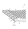
- the infill includes a plurality of acoustic chambers 56 (only one labelled for clarity).
- the forwardmost wall 58A of the infill 40 defines one of the walls of the gap 44A shown in Figures 2 and 3 .
- a plurality of projections (or ribs) 60A protrude from the wall 58A, and in use protrude in to the gap 44A and compress the sealing strip 46A.
- the projections are arranged so as to protrude into the gap 44A less towards the gas-washed surface 50 of the infill than at a position away from the gas washed surface.
- the projections 60A provided on the wall 58A of the infill provide multiple functions. Firstly, the projections compress the sealing strip 46A which contributes to retention of the sealing strip 46A in the gap 44A. It has been found that providing a hollow tubular sealing strip made from a compressible material and compressing the sealing strip in the gap provides a damping effect. This is particularly applicable in this embodiment because the projections 60A are configured and arranged so as to form a series of pockets (open or closed) in the sealing strip which has surprisingly been found to further contribute to damping.
- the projections 60A further provide a stiffening feature to the end wall 58A of the infill 40. Yet further, the projections 60A increase the surface area to which the sealant 48A can bond, further improving retention of the sealant in the gap 44A.
- the above described sealing arrangement advantageously seals the gap 44A between the acoustic panel 34A and the infill 40 and has lower weight than sealing arrangements of the prior art, because the sealing strip 46A is lighter in weight than if sealant alone were used to fill the gap 44A.
- the lip 52A improves the retention of the sealing strip 46A and the sealant 48A in the gap 44A.
- the combination of the sealing strip and the projections 60A provides an improved damping effect compared to the use of sealant alone.
- the sealing arrangement also has advantages in terms of manufacture and service.
- To fill the gap 44A between the infill 40 and the acoustic panel 34A firstly the sealing strip 46A is placed in the gap 44A. Then the sealant 48A is injected on top of the sealing strip 46A and underneath the lip 52A. In this way, much less sealant is required compared to the sealing arrangements of the prior art, this means that the time taken to cure the sealant can be reduced. In service, the time taken to the remove the infill 40 during maintenance is also reduced because it is quicker and easier to remove the smaller volume of sealant of the described embodiment than the larger volume of sealant of the prior art.
- the gas washed surface 36A of the acoustic panel 34A is often porous. This means that water can enter in acoustic panel.
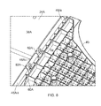
- drainage holes 62A are provided to drain the water from the acoustic panel 34A.
- the drainage holes exit the acoustic panel at the gap 44A.
- Channels 64 are provided in the infill to permit drainage of water from the gap 44A.
- the sealing strip 46A is provided as a plurality of sealing strip members 46Ai, 46Aii and 46Aiii. The sealing strip members are spaced in the gap 44A so as to avoid covering the drainage holes 62A.
- FIG. 7 a similar arrangement is used between the infill 40 and an acoustic panel 34A positioned aft of the OGVs. Similar to the sealing arrangement previously described, a sealing strip 46B and sealant 48B are used to seal a gap 44B between the infill 40 and the acoustic panel 34B. Similarly to previously described, the infill 40 is provided at a rear end with a lip 52B that acts to retain the sealant and sealing strip in the gap 44B. In the present embodiment, no projections are provided on the rear wall; instead the rear wall is a substantially smooth surface. However, in alternative embodiments the rear wall may include projections similar to those described for the front wall 58A of the infill 40.
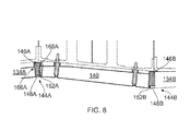
- a sealing strip 146A is positioned in the gap 144A and a sealant 148A fills the remainder of the gap 144A and forms part of the gas washed surface of the bypass duct.
- a sealant 148A fills the remainder of the gap 144A and forms part of the gas washed surface of the bypass duct.
- the cross-section of the sealing strip 146A and the configuration of the lip 152A of the infill 140A differs to that of the previously described embodiment.
- the sealing strip 146A When in a non-compressed state (i.e. not positioned in the gap 144A), the sealing strip 146A has a substantially rectangular cross section. Once positioned in the gap 144A the sealing strip deforms to include a stepped portion 166A that is seated beneath the acoustic panel 134A.
- the lip 152A of the infill 140 is configured to extend radially away from the gas washed surface towards the sealing strip 146A.
- the lip 152A is configured to be seated on and to compress and deform the sealing strip 146A so as to form a stepped portion 168A of the sealing strip 146A. Compressing and deforming the sealing strip 146A to form the stepped portion 168A further improves retention of the sealing strip 146A in the gap 144A.
- a sealing strip 146B and a sealant 148B are used to fill the gap.
- the configuration of the lip 152B differs from the lip at the front of the infill 140.
- the sealing strip 148B In an uncompressed state, the sealing strip 148B is substantially rectangular in cross section. Once positioned in the gap 144B, the sealing strip 148B is compressed and deformed to be substantially trapezoidal in cross section. In alternative embodiments, the sealing strip may be trapezoidal in an uncompressed state.
- the lip 152B extends radially away from the gas washed surface of the bypass duct, and abuts a radially inner surface of the sealing strip 148B to retain the sealing strip in position in the gap 144B.
- Figure 9 illustrates a gap 244B at the rear of the infill 240, but a similar arrangement could also be used at the front of the infill.
- the sealing strip 246B is similar to the sealing strip shown in Figures 3 to 6 .
- a lip 270B is provided on the acoustic panel 234B as well as a lip 244B being provided on the infill 240.
- the sealant 248B fills the gap between the sealing strip and the gas washed surface of the bypass duct. The provision of two lips improves retention of the sealant and the sealing strip.
- the sealing strip may have a cross section of a circular ring 346 as shown in Figure 10A ; a substantially solid circle 446 as shown in Figure 10B ; substantially solid rectangle with rounded corners 546 as shown in Figure 10C ; a hollow rectangle with rounded corners 646 as shown in Figure 10D ; or a hollow or full oval 746 as shown in Figure 10E .
- the sealing strip may have any other suitable cross section.
- the lip is located to be aligned with the gas washed surface of the bypass duct, but in alternative embodiments the lip may be offset from the gas washed surface. Additionally or alternatively, the lip may be provided on the acoustic panel in addition to or as an alternative to being provided on the infill.
- the infill panel is provided with projections 60 which act as compression features to compress and/or locate the sealing strip.
- the projections extend radially, but in alternative embodiments the projections may extend circumferentially, for example as indicated at 860 in Figure 11 . Further alternatively, projections may be additionally or alternatively provided on the acoustic liner.
- projections are provided at the front of the infill but not at the rear of the infill. In alternative embodiments, projections may be provided at the rear of the infill additionally or alternatively to the projections on the front of the infill.
- sealing arrangements are positioned between an infill and an acoustic panel, but in alternative embodiments the sealing arrangement may be used in any location where there is a gap between two adjacent components; for example, between an OGV and an infill, between adjacent infills, or between adjacent panels.
- the outer or inner casing element e.g. fan case, mount ring, rear case or outer core casing
- the sealing arrangement may seal a gap between the casing element and an acoustic panel.
- the sealant is positioned directly adjacent the sealing strip.
- a sealing enhancing or binding member may be located between the sealing strip and the sealant.
- the sealing strip may be wrapped in a meshed material and the sealant may be adjacent and bond to the meshed material and the sealing strip.
- FIG. 12 A further alternative embodiment is illustrated in Figure 12 .
- the sealing arrangement of Figure 12 includes a sealing strip 946B positioned in the gap 944B between the infill 940B and the acoustic panel 934B.
- a sealant 948B fills the remainder of the gap 944B between the sealing strip and the gas washed surfaces 950B, 936B of the infill 940B and the acoustic panel 934B, so as to form a surface coincident with the gas washed surfaces of the infill and the acoustic panel.
- the sealing strip 946B is an elongate strip that extends between the infill and the acoustic panel.
- Each axial end of the sealing strip is bulbous in shape, such that the shape of the sealing strip could be considered to be a dog-bone shape.
- the infill and the acoustic panel each include a groove shaped to closely accommodate the bulbous ends of the sealing strip.
Landscapes
- Engineering & Computer Science (AREA)
- Mechanical Engineering (AREA)
- General Engineering & Computer Science (AREA)
- Chemical & Material Sciences (AREA)
- Combustion & Propulsion (AREA)
- Structures Of Non-Positive Displacement Pumps (AREA)
Abstract
Description
- The present invention relates to a gas turbine engine.
- Turbofan gas turbine engines (which may be referred to simply as 'turbofans') are typically employed to power aircraft. Turbofans are particularly useful on commercial aircraft where fuel consumption is a primary concern. Typically a turbofan gas turbine engine will comprise an axial fan driven by an engine core. The engine core is generally made up of one or more turbines which drive respective compressors via coaxial shafts. The fan is usually driven directly off an additional lower pressure turbine in the engine core.
- The fan draws air into the engine and the air is discharged through a bypass duct which provides a portion of the engine thrust.
- Positioned within the bypass duct, axially rearward of the fan, a series of outlet guide vanes (OGVs) are arranged and positioned between an inner and outer casing that define the bypass duct. A series of acoustic panels line the inner and outer casing. To prevent air recirculating behind the acoustic panels and to provide a smooth surface for air flow through the engine, an infill panel is provided between each of the OGVs.
- The infill panel is generally a moulded component that includes acoustic chambers, and is typically bolted to the respective inner or outer casing.
- A gap exists between the infill panel and the acoustic panel. The distance of the gap can vary depending on a number of factors, including how tightly sections of the inner and/or outer case are connected (e.g. bolted) together. It is important that the gap between the infill panel and acoustic panel is sealed so as to create a smooth gas washed surface, but also to prevent air flow recirculating behind the acoustic panel and/or infill which could cause damage to the engine.
- The conventional method to fill the gap is to use a sealant such as polysulphide.
-
Figure 1 shows an arrangement of an infill and forward and rearward acoustic panels forming part of an outer casing assembly of the prior art. The casing assembly includes afan case 1035 substantially coaxial with and connected to amount ring 1039. Themount ring 1039 is substantially coaxial with and connected to arear case 1041.Acoustic panels 1034A line the fan case andacoustic panels 1034B line the rear panel. The fan outlet guide vanes (OGVs) 1032 are connected to the mount ring, typically via bolts. Aninfill panel 1040 is positioned between each OGV to fill a void between the forwardacoustic panel 1034A and the rearwardacoustic panel 1034B. A gap 1044A is formed between the forwardacoustic panel 1034A and the infill panel 1044. This gap is filled withpolysulphide sealant 1048A. - Use of a sealant is advantageous because an effective seal can be produced independently of the gap size. However, the use of sealant to fill the gap leads to increase weight of the engine, increased lead time due to the cure time for the sealant and increased cost. A further problem is that in-service-support may require the removal of a panel, which is time consuming because of the time taken to completely remove the sealant and then re-inject and cure the sealant.
- The present invention seeks to address one or more of the problems associated with connecting two components having a gas washed surface in gas turbine engines of the prior art.
- A first aspect of the invention provides a gas turbine engine having a fan and a bypass duct for discharging airflow from the fan to generate engine thrust, the bypass duct comprising:
- a first component and a second component each having a gas washed surface, the first component being positioned adjacent the second component with a gap therebetween;
- a sealing strip positioned in the gap between the first component and the second component distal to the gas washed surfaces of the first and second components; and
- a sealant positioned between the first and second component proximal to the gas washed surfaces of the first and second components, so as to seal the gap between the first component and the second component from airflow through the bypass duct.
- The use of a sealing strip and sealant effectively seals the gap between the first and second components and provides a smooth gas washed surface of the bypass duct. The provision of a sealing strip instead of only using sealant, as in the prior art, has several advantages including weight reduction, reduction in assembly time, and in some embodiments the sealing strip has been found to surprisingly have a damping effect. Use of the sealing strip is advantageous during servicing because it reduces the time required to remove and replace the seal.
- The first component may comprise a lip to limit movement of the sealing strip and/or sealant relative to the first component. The provision of a lip aids retention of the sealing strip and/or sealant in the gap between the first and second components. Additionally or alternatively, the second component may comprise a lip to limit movement of the sealing strip and/or sealant relative to the second component.
- The lip may be positioned to contact the sealant and form part of the gas washed surface of the first component. In such an arrangement the lip aids retention of both the sealing strip and the sealant. In alternative embodiments the lip may be positioned to be radially offset from the gas washed surface into the gap between the first and second components. Further alternatively, the lip may form part of the gas washed surface and the lip may extend radially into the gap between the first and second component and contact the sealing strip.
- The sealing strip may be made from a compressible material, e.g. a rubber, elastomer or compressible closed cell foam. Use of such materials has been found to be advantageous in terms of ease of location in the gap between the first and second components. Furthermore, such materials have been found to have a damping effect.
- The sealing strip may form a hollow tube. The use of a hollow tube is further advantageous in reducing weight, easing location and when a compressible material (e.g. rubber, elastomer, compressible closed cell foam) is used, the hollow tube construction has been found to further improve damping. A sealing strip formed of a hollow tube and made from a compressible material has been found to provide an optimal solution because the flexibility of such a sealing strip ensures effective sealing of the gap between the first and second components, and also provides a damping function.
- Alternatively, the sealing strip may have a solid cross section.
- The sealing strip may have a cross section that is substantially rectangular with rounded ends or substantially circular. Alternatively, the sealing strip may have a cross section that is substantially rectangular or substantially oval.
- The sealing strip may be dimensioned so as to be in a compressed or near compressed state when positioned in the gap.
- The first or the second component may comprise one or more compression features for compressing the sealing strip in the gap. The compression features help to retain the sealing strip in the gap, and can in some cases increase the surface area to which the sealant bonds. In embodiments where a hollow compressible tube forms the sealing strip, the compression features can further improve damping performance. For example, the compression features may form a series of "pockets", it has unexpectedly been found that these "pockets" contribute in improving damping.
- The compression feature may be a radially extending rib. Ribs have been found to be additionally advantageous because they provide additional rigidity to the edge of the first or the second component. Alternatively, the compression feature may be a circumferentially extending rib.
- In alternative embodiments, opposing faces of the first component and the second component may comprise a groove. The sealing strip may extend into the groove of the first and second components. The sealing strip may have two bulbous ends, for example the shape of the sealing strip may be considered to be dog-bone-shaped. The bulbous ends may be positioned in the grooves of the first and second components. The groove of the first and/or second component may be shaped to be complimentary to the bulbous ends such that the sealing strip interlocks with the first and/or second component.
- The bypass duct may comprise an inner casing assembly and an outer casing assembly that define an air flow passage. The first and second component may be components of said inner and/or said outer casing assemblies. The inner and/or outer casing assemblies may comprise a casing element (e.g. a fan case, mount ring, or rear case) and one or more liners or infills that are connected to the casing element on a gas-washed side of the casing element.
- The first and/or second component may be a liner or infill. For example, the first component may be an infill and the second component may be a liner (e.g. an acoustic liner). Alternatively, the first and second component may both be a liner or the first and second component may both be an infill. In a further alternative embodiment the first or second component may be a casing element.
- The gas turbine engine may comprise a plurality of outlet guide vanes (e.g. fan outlet guide vanes). The first component may be an infill positioned between two adjacent outlet guide vanes and the second component may be a liner e.g. an acoustic liner. The invention has been found to be particularly advantageous in such an application.
- The outlet guide vanes (OGVs) may be connected to a casing element (e.g. mount ring) and the infill may be mounted to said casing element.
- The infill may have a forward end and a rearward end and a liner may be positioned adjacent the infill at both the forward end and the rearward end. A sealing strip and sealant as described above may be used to seal a gap between the infill and the liners at both the forward end and rearward end of the infill.
- One or more drainage holes may be provided in the liner and the sealing strip may be provided as a plurality of strip members, the strip members being spaced so as to permit water to exit the drainage holes formed in the liner.
- The first and/or second component may be a moulded component. Alternatively, the first or second component may be a composite component. In an exemplary embodiment, the first component may be a moulded infill and the second component may be a composite liner (e.g. an acoustic liner).
- A second aspect of the invention provides a gas turbine engine having a fan and a bypass duct for discharging airflow from the fan to generate engine thrust, the bypass duct comprising:
- a first component and a second component each having a gas washed surface, the first component being positioned adjacent the second component with a gap therebetween; and
- a sealant positioned between the first and second component so as to seal the gap between the first component and the second component from airflow through the bypass duct;
- wherein the first component comprises a lip to limit movement of the sealant relative to the first component.
- The gas turbine engine may comprise a first sealing strip positioned in the gap between the first component and the second component distal to the gas washed surfaces of the first and second components, and the sealant may be positioned proximal to a gas washed surface of the first and second components.
- The lip may be configured to limit movement of the sealing strip in addition to limiting movement of the sealant relative to the first component.
- The second component may comprise a lip to limit movement of the sealing strip and/or sealant relative to the second component.
- As will be appreciated by the person skilled in the art, where applicable, any of, or any combination of, the optional features of the first aspect may be applied to the second aspect. A third aspect of the invention provides a gas turbine engine having a fan and a bypass duct for discharging airflow from the fan to generate engine thrust, the bypass duct comprising:
- a first component, a second component and a third component each having a gas washed surface, the first component being positioned adjacent and between the second and third components with a gap therebetween;
- a first sealing strip positioned in the gap between the first component and the second component distal to the gas washed surfaces of the first and second components;
- a second sealing strip positioned in the gap between the first component and the third component distal to the gas washed surfaces of the first and third components;
- a first sealant positioned between the first and second component proximal to the gas washed surfaces of the first and second components, so as to seal the gap between the first component and the second component from airflow through the bypass duct; and
- a second sealant positioned between the first and third component proximal to the gas washed surfaces of the first and third components, so as to seal the gap between the first component and the third component from airflow through the bypass duct.
- The first component may be an infill and the second and third components may be a liner (e.g. an acoustic liner). For example, the first component may be an infill positioned between two adjacent outlet guide vanes (e.g. fan outlet guide vanes).
- As will be appreciated by the person skilled in the art, where applicable, any of, or any combination of, the optional features of the first aspect may be applied to the third aspect of the invention.
- A fourth aspect of the invention provides a method of sealing a gap between two adjacent components of a bypass duct of a gas turbine engine, the two adjacent components each having a gas washed surface, the method comprising:
- positioning a sealing strip in the gap between the two adjacent components; and
- injecting a sealant in the gap between the two adjacent components on a gas washed side of the adjacent components so as to seal the gap from airflow through the bypass duct.
- The method may be such as to form a gas turbine engine according to the first and or second aspect of the invention.
- The invention will now be described, by way of example only, with reference to the accompanying drawings in which:
-
Figure 1 is a partial cross section through an outer casing assembly of a bypass duct of a gas turbine engine of the prior art; -
Figure 2 is a cross-section through the rotational axis of a high-bypass gas turbine engine; -
Figure 3 is a partial cross section through an infill, an acoustic panel positioned fore of the infill and a sealing arrangement sealing a gap therebetween; -
Figure 4 is a perspective view of the acoustic panel, infill and sealing arrangement ofFigure 3 ; -
Figure 5 shows a perspective view from a non-gas-washed surface of the infill ofFigures 2 and3 ; -
Figure 6 shows a perspective view from a non-gas-washed surface of the acoustic panel, infill and sealing arrangement ofFigures 3 and4 ; -
Figure 7 shows a partial cross section though the infill shown inFigures 2 to 5 , an acoustic panel positioned aft of the infill and a sealing arrangement sealing a gap therebetween; -
Figure 8 shows a partial cross section through an alternative infill with an acoustic panel positioned fore and aft of the infill and a sealing arrangement sealing a gap between the infill and the acoustic panels; -
Figure 9 shows a partial cross section through a further alternative infill with an acoustic panel positioned aft of the infill and a sealing arrangement sealing a gap therebetween; -
Figures 10A to 10E show a variety of cross sections of a sealing strip that may form part of a sealing arrangement similar to those shown in any one ofFigures 3 ,4 and6 to 9 ; -
Figure 11 shows a partial cross section through a yet further alternative infill with an acoustic panel positioned aft of the infill and a sealing arrangement sealing a gap therebetween; and -
Figure 12 shows a partial cross section through an infill with an acoustic panel positioned aft of the infill and an alternative sealing arrangement sealing a gap therebetween. - With reference to
Figure 2 a bypass gas turbine engine is indicated at 10. Theengine 10 comprises, in axial flow series, anair intake duct 11,fan 12, abypass duct 13, anintermediate pressure compressor 14, ahigh pressure compressor 16, acombustor 18, ahigh pressure turbine 20, anintermediate pressure turbine 22, alow pressure turbine 24 and anexhaust nozzle 25. Thefan 12,compressors turbines gas turbine engine 10 and so define the axial direction of the gas turbine engine. - In the present application a fore or a forward direction F and an aft or a rearward direction R is defined with respect to a generally axial direction of working airflow through the gas turbine engine.
- Air is drawn through the
air intake duct 11 by thefan 12 where it is accelerated. A significant portion of the airflow is discharged through thebypass duct 13 generating a corresponding portion of the engine thrust. The remainder is drawn through theintermediate pressure compressor 14 into what is termed the core of theengine 10 where the air is compressed. A further stage of compression takes place in thehigh pressure compressor 16 before the air is mixed with fuel and burned in thecombustor 18. The resulting hot working fluid is discharged through thehigh pressure turbine 20, theintermediate pressure turbine 22 and thelow pressure turbine 24 in series where work is extracted from the working fluid. The work extracted drives theintake fan 12, theintermediate pressure compressor 14 and thehigh pressure compressor 16 viashafts exhaust nozzle 25 generating the remainder of theengine 10 thrust. - An inner and outer casing assembly defines a section of the
bypass duct 13. A circumferential series of outlet guide vanes (OGVs) 32 are positioned between the inner and outer casing assemblies. - The inner and outer casing assemblies include a series of acoustic panels positioned fore and aft of the OGVs. Acoustic panels are well understood in the art and can have any suitable construction. In the present embodiment, the acoustic panel is formed of a layer of honeycomb cells backed on a non-gas-washed face with an impervious sheet and backed on a gas-washed face with a porous sheet. An
acoustic panel 34A positioned fore of the OGVs is illustrated inFigures 2 and3 and has a non-gas-washed surface (or face) 38A and a gas-washed surface (or face) 36A. - The
OGV 32 connects to an inner and an outer casing element (e.g. a mount ring of the outer casing assembly) at a position radially set back from the gas-washedsurface 36A of the acoustic panel. To prevent air flow penetrating the casing structure, e.g. circulating the non-gas washedsurface 38A of the acoustic panel, which could cause damage to the engine structure, and also to provide a bypass duct with a smooth gas washed surface, aninfill 40 is provided. The infill is positioned between two adjacent OGVs and mounted to the respective casing element, in the present embodiment using bolts throughholes 42. - A
gap 44A is provided between theacoustic liner 34A and theinfill 40. To fill thegap 44A a sealing arrangement is used. - The sealing arrangement includes a
sealing strip 46A positioned in thegap 44A between theinfill 40 and theacoustic panel 34A. Asealant 48A fills the remaining gap and forms a surface coincident with the gas washedsurface 50 of theinfill 40 and the gas washedsurface 36A of theacoustic panel 34A. In the presently described embodiment, alip 52A protrudes from an edge of theinfill 40 and extends so as to protrude over the top of a portion of thesealant 48A. - The sealing
strip 46A is formed from a closed cell compressible foam. However, in alternative embodiments the sealing strip may be formed from a rubber or elastomer. The sealing strip is formed as a hollow tube and has a substantially rounded rectangle cross section (i.e. the sealing strip has a cross section where the outer perimeter can be considered to be defined by a rectangle having a semi-circle connected at each longitudinal end). The sealing strip is positioned in the gap such that one of the rounded ends 54A of the sealing strip is in contact with thesealant 48A (once the sealant is injected into thegap 44A). The provision of rounded ends instead of flat ends increases the contact area to which thesealant 48A can bond. Further, as will be discussed below, a rounded rectangular cross section can optimise damping compared to other suitable shaped sealing strips. - The
sealant 48A is formed of polysulphide, but any suitable sealant may be used. The sealant is injected into the remaining gap between theinfill 40 and theacoustic panel 34A. As can be seen most clearly inFigure 3 , thesealant 48A contacts therounded end 54A of the sealing strip, bonds thereto and projects underneath thelip 52A of theinfill 40. In this way, thelip 52A of theinfill 40 acts to retain thesealant 48A and thesealing strip 46A in thegap 44A. - Referring to
Figure 5 , a forward portion of theinfill 40 is shown in more detail. Theinfill 40 is a moulded component. The infill includes a plurality of acoustic chambers 56 (only one labelled for clarity). Theforwardmost wall 58A of theinfill 40 defines one of the walls of thegap 44A shown inFigures 2 and3 . A plurality of projections (or ribs) 60A (only one labelled for clarity) protrude from thewall 58A, and in use protrude in to thegap 44A and compress thesealing strip 46A. In the present embodiment the projections are arranged so as to protrude into thegap 44A less towards the gas-washedsurface 50 of the infill than at a position away from the gas washed surface. - The
projections 60A provided on thewall 58A of the infill provide multiple functions. Firstly, the projections compress thesealing strip 46A which contributes to retention of the sealingstrip 46A in thegap 44A. It has been found that providing a hollow tubular sealing strip made from a compressible material and compressing the sealing strip in the gap provides a damping effect. This is particularly applicable in this embodiment because theprojections 60A are configured and arranged so as to form a series of pockets (open or closed) in the sealing strip which has surprisingly been found to further contribute to damping. Theprojections 60A further provide a stiffening feature to theend wall 58A of theinfill 40. Yet further, theprojections 60A increase the surface area to which thesealant 48A can bond, further improving retention of the sealant in thegap 44A. - The above described sealing arrangement advantageously seals the
gap 44A between theacoustic panel 34A and theinfill 40 and has lower weight than sealing arrangements of the prior art, because thesealing strip 46A is lighter in weight than if sealant alone were used to fill thegap 44A. - Further the
lip 52A improves the retention of the sealingstrip 46A and thesealant 48A in thegap 44A. Finally, the combination of the sealing strip and theprojections 60A provides an improved damping effect compared to the use of sealant alone. - The sealing arrangement also has advantages in terms of manufacture and service. To fill the
gap 44A between theinfill 40 and theacoustic panel 34A, firstly the sealingstrip 46A is placed in thegap 44A. Then thesealant 48A is injected on top of the sealingstrip 46A and underneath thelip 52A. In this way, much less sealant is required compared to the sealing arrangements of the prior art, this means that the time taken to cure the sealant can be reduced. In service, the time taken to the remove theinfill 40 during maintenance is also reduced because it is quicker and easier to remove the smaller volume of sealant of the described embodiment than the larger volume of sealant of the prior art. - Referring to
Figure 6 , the gas washedsurface 36A of theacoustic panel 34A is often porous. This means that water can enter in acoustic panel. To drain the water from theacoustic panel 34A,drainage holes 62A are provided. The drainage holes exit the acoustic panel at thegap 44A. Channels 64 (only one labelled for clarity) are provided in the infill to permit drainage of water from thegap 44A. To permit water to flow from the drainage holes 62A to thechannels 64, the sealingstrip 46A is provided as a plurality of sealing strip members 46Ai, 46Aii and 46Aiii. The sealing strip members are spaced in thegap 44A so as to avoid covering the drainage holes 62A. - Referring now to
Figure 7 , a similar arrangement is used between theinfill 40 and anacoustic panel 34A positioned aft of the OGVs. Similar to the sealing arrangement previously described, a sealingstrip 46B andsealant 48B are used to seal agap 44B between theinfill 40 and theacoustic panel 34B. Similarly to previously described, theinfill 40 is provided at a rear end with alip 52B that acts to retain the sealant and sealing strip in thegap 44B. In the present embodiment, no projections are provided on the rear wall; instead the rear wall is a substantially smooth surface. However, in alternative embodiments the rear wall may include projections similar to those described for thefront wall 58A of theinfill 40. - Referring now to
Figure 8 , an alternative sealing arrangement is shown. Similar features are given similar reference numerals as the previously described embodiment, but with a suffix "1 ". Only the differences will be described in detail here. - Referring firstly to the
gap 144A at the front of theinfill panel 140, similar to the previously described embodiment, a sealingstrip 146A is positioned in thegap 144A and asealant 148A fills the remainder of thegap 144A and forms part of the gas washed surface of the bypass duct. However, in the embodiment shown inFigure 8 the cross-section of the sealingstrip 146A and the configuration of thelip 152A of the infill 140A differs to that of the previously described embodiment. - When in a non-compressed state (i.e. not positioned in the
gap 144A), the sealingstrip 146A has a substantially rectangular cross section. Once positioned in thegap 144A the sealing strip deforms to include a steppedportion 166A that is seated beneath theacoustic panel 134A. - The
lip 152A of theinfill 140 is configured to extend radially away from the gas washed surface towards the sealingstrip 146A. Thelip 152A is configured to be seated on and to compress and deform thesealing strip 146A so as to form a steppedportion 168A of the sealingstrip 146A. Compressing and deforming the sealingstrip 146A to form the steppedportion 168A further improves retention of the sealingstrip 146A in thegap 144A. - Now referring to the
gap 144B at the rear of theinfill 140, similarly to thegap 144B at the front of theinfill 140, a sealingstrip 146B and asealant 148B are used to fill the gap. However, the configuration of thelip 152B differs from the lip at the front of theinfill 140. - In an uncompressed state, the sealing
strip 148B is substantially rectangular in cross section. Once positioned in thegap 144B, the sealingstrip 148B is compressed and deformed to be substantially trapezoidal in cross section. In alternative embodiments, the sealing strip may be trapezoidal in an uncompressed state. Thelip 152B extends radially away from the gas washed surface of the bypass duct, and abuts a radially inner surface of the sealingstrip 148B to retain the sealing strip in position in thegap 144B. - A yet further alternative embodiment is shown in
Figure 9. Figure 9 illustrates agap 244B at the rear of the infill 240, but a similar arrangement could also be used at the front of the infill. In the embodiment shown inFigure 9 , the sealingstrip 246B is similar to the sealing strip shown inFigures 3 to 6 . However, a lip 270B is provided on theacoustic panel 234B as well as alip 244B being provided on the infill 240. Thesealant 248B fills the gap between the sealing strip and the gas washed surface of the bypass duct. The provision of two lips improves retention of the sealant and the sealing strip. - Referring now to
Figures 10A to 10E , further alternative cross sections for a sealing strip are shown. For example, the sealing strip may have a cross section of acircular ring 346 as shown inFigure 10A ; a substantiallysolid circle 446 as shown inFigure 10B ; substantially solid rectangle withrounded corners 546 as shown inFigure 10C ; a hollow rectangle withrounded corners 646 as shown inFigure 10D ; or a hollow orfull oval 746 as shown inFigure 10E . As will be appreciated by the person skilled in the art, the sealing strip may have any other suitable cross section. - It will be appreciated by one skilled in the art that, where technical features have been described in association with one embodiment, this does not preclude the combination or replacement with features from other embodiments where this is appropriate. Furthermore, equivalent modifications and variations will be apparent to those skilled in the art from this disclosure. Accordingly, the exemplary embodiments of the invention set forth above are considered to be illustrative and not limiting.
- For example, in the described embodiments the lip is located to be aligned with the gas washed surface of the bypass duct, but in alternative embodiments the lip may be offset from the gas washed surface. Additionally or alternatively, the lip may be provided on the acoustic panel in addition to or as an alternative to being provided on the infill.
- The infill panel is provided with projections 60 which act as compression features to compress and/or locate the sealing strip. In the described embodiment the projections extend radially, but in alternative embodiments the projections may extend circumferentially, for example as indicated at 860 in
Figure 11 . Further alternatively, projections may be additionally or alternatively provided on the acoustic liner. - In the described embodiment, projections are provided at the front of the infill but not at the rear of the infill. In alternative embodiments, projections may be provided at the rear of the infill additionally or alternatively to the projections on the front of the infill.
- The described sealing arrangements are positioned between an infill and an acoustic panel, but in alternative embodiments the sealing arrangement may be used in any location where there is a gap between two adjacent components; for example, between an OGV and an infill, between adjacent infills, or between adjacent panels.
- In a contemplated embodiment, the outer or inner casing element (e.g. fan case, mount ring, rear case or outer core casing) to which the OGVs are connected may extend radially into the bypass duct by a greater distance to the described embodiments removing the need for an infill. In such an embodiment the sealing arrangement may seal a gap between the casing element and an acoustic panel.
- In the described embodiments the sealant is positioned directly adjacent the sealing strip. However, in alternative embodiments a sealing enhancing or binding member may be located between the sealing strip and the sealant. For example, the sealing strip may be wrapped in a meshed material and the sealant may be adjacent and bond to the meshed material and the sealing strip.
- A further alternative embodiment is illustrated in
Figure 12 . The sealing arrangement ofFigure 12 includes asealing strip 946B positioned in thegap 944B between theinfill 940B and theacoustic panel 934B. Asealant 948B fills the remainder of thegap 944B between the sealing strip and the gas washedsurfaces infill 940B and theacoustic panel 934B, so as to form a surface coincident with the gas washed surfaces of the infill and the acoustic panel. The sealingstrip 946B is an elongate strip that extends between the infill and the acoustic panel. Each axial end of the sealing strip is bulbous in shape, such that the shape of the sealing strip could be considered to be a dog-bone shape. The infill and the acoustic panel each include a groove shaped to closely accommodate the bulbous ends of the sealing strip.
Claims (15)
- A gas turbine engine having a fan and a bypass duct for discharging airflow from the fan to generate engine thrust, the bypass duct comprising:a first component and a second component each having a gas washed surface, the first component being positioned adjacent the second component with a gap therebetween;a sealing strip positioned in the gap between the first component and the second component distal to the gas washed surfaces of the first and second components; anda sealant positioned between the first and second component proximal to the gas washed surfaces of the first and second components, so as to seal the gap between the first component and the second component from airflow through the bypass duct.
- The gas turbine engine according to claim 1, wherein the first component comprises a lip to limit movement of the sealing strip and/or sealant relative to the first component.
- The gas turbine engine according to claim 2, wherein the lip is positioned to contact the sealant and form part of the gas washed surface of the first component.
- The gas turbine engine according to any one of the previous claims, wherein the sealing strip is made from a rubber, elastomer or compressible closed cell foam.
- The gas turbine engine according to claim 4, wherein the sealing strip forms a hollow tube.
- The gas turbine engine according to any one of the previous claims, wherein the sealing strip has cross section that is substantially rectangular with rounded ends or substantially circular.
- The gas turbine engine according to any one of the previous claims, wherein the first or the second component comprises one or more compression features for compressing the sealing strip in the gap.
- The gas turbine engine according to claim 7, wherein the compression feature comprises one or more radially extending ribs.
- The gas turbine engine according to any one of claims 1 to 3, wherein opposing faces of the first component and the second component comprise a groove, and wherein the sealing strip extends into the groove of the first and second components.
- The gas turbine engine according to claim 9, wherein the sealing strip has two bulbous ends, the bulbous ends being positioned in the grooves of the first and second components.
- The gas turbine engine according to any one of the previous claims, wherein the first and/or second component is a liner or infill.
- The gas turbine engine according to claim 11 comprising a plurality of outlet guide vanes, and wherein the first component is an infill positioned between two adjacent outlet guide vanes and the second component is a liner.
- The gas turbine engine according to claim 12, wherein the infill has a forward end and a rearward end and a liner is positioned adjacent the infill at both the forward end and the rearward end, and a sealing strip and sealant of the gas turbine engine of any of the preceding claims is used to seal a gap between the infill and the liners at both the forward end and rearward end of the infill.
- The gas turbine engine according to claim 12 or 13, wherein one or more drainage holes are provided in the liner and the sealing strip is provided as a plurality of strip members, the strip members being spaced so as to permit water to exit the drainage holes formed in the liner.
- A method of sealing a gap between two adjacent components of a bypass duct of a gas turbine engine, the two adjacent components each having a gas washed surface, the method comprising:positioning a sealing strip in the gap between the two adjacent components; andinjecting a sealant in the gap between the two adjacent components on a gas washed side of the adjacent components so as to seal the gap from airflow through the bypass duct.
Applications Claiming Priority (1)
| Application Number | Priority Date | Filing Date | Title |
|---|---|---|---|
| GB201319256A GB201319256D0 (en) | 2013-10-31 | 2013-10-31 | Gas turbine engine |
Publications (2)
| Publication Number | Publication Date |
|---|---|
| EP2868869A1 true EP2868869A1 (en) | 2015-05-06 |
| EP2868869B1 EP2868869B1 (en) | 2018-12-12 |
Family
ID=49767477
Family Applications (1)
| Application Number | Title | Priority Date | Filing Date |
|---|---|---|---|
| EP14185908.2A Active EP2868869B1 (en) | 2013-10-31 | 2014-09-23 | Gas turbine engine gap seal made of a sealing strip covered by a sealant |
Country Status (3)
| Country | Link |
|---|---|
| US (1) | US10047698B2 (en) |
| EP (1) | EP2868869B1 (en) |
| GB (1) | GB201319256D0 (en) |
Cited By (1)
| Publication number | Priority date | Publication date | Assignee | Title |
|---|---|---|---|---|
| EP3159522A1 (en) * | 2015-10-20 | 2017-04-26 | Airbus Helicopters | A gas ejection duct with acoustic treatment, an aircraft, and a method of fabricating such a duct |
Families Citing this family (2)
| Publication number | Priority date | Publication date | Assignee | Title |
|---|---|---|---|---|
| EP3853465B1 (en) * | 2018-09-20 | 2022-07-27 | Safran Aircraft Engines | Acoustic management, on a turbomachine or a nacelle |
| GB201914723D0 (en) | 2019-10-11 | 2019-11-27 | Rolls Royce Plc | Cleaning system and a method of cleaning |
Citations (2)
| Publication number | Priority date | Publication date | Assignee | Title |
|---|---|---|---|---|
| US20110037233A1 (en) * | 2009-08-14 | 2011-02-17 | Rolls-Royce Plc | Sealing assembly |
| EP2492448A2 (en) * | 2011-02-22 | 2012-08-29 | General Electric Company | Sealing Device And Method For Providing A Seal In A Turbine System |
Family Cites Families (7)
| Publication number | Priority date | Publication date | Assignee | Title |
|---|---|---|---|---|
| US5776579A (en) * | 1996-03-28 | 1998-07-07 | The Boeing Company | Structural bonding with encapsulated foaming adhesive |
| US6371411B1 (en) * | 1999-11-23 | 2002-04-16 | The Boeing Company | Method and apparatus for aircraft inlet ice protection |
| GB2385382B (en) | 2002-02-13 | 2006-02-15 | Rolls Royce Plc | A cowl structure for a gas turbine engine |
| FR2844303B1 (en) | 2002-09-10 | 2006-05-05 | Airbus France | TUBULAR ACOUSTICAL ATTENUATION PIECE FOR AIRCRAFT REACTOR AIR INTAKE |
| DE102004030597A1 (en) * | 2004-06-24 | 2006-01-26 | Rolls-Royce Deutschland Ltd & Co Kg | Turbomachine with external wheel jet generation at the stator |
| US7328771B2 (en) | 2004-07-27 | 2008-02-12 | United Technologies Corporation | Zero acoustic splice fan case liner |
| GB2443830B (en) * | 2006-11-15 | 2010-01-20 | Rolls Royce Plc | Cowling arrangement |
-
2013
- 2013-10-31 GB GB201319256A patent/GB201319256D0/en not_active Ceased
-
2014
- 2014-09-23 US US14/494,197 patent/US10047698B2/en active Active
- 2014-09-23 EP EP14185908.2A patent/EP2868869B1/en active Active
Patent Citations (2)
| Publication number | Priority date | Publication date | Assignee | Title |
|---|---|---|---|---|
| US20110037233A1 (en) * | 2009-08-14 | 2011-02-17 | Rolls-Royce Plc | Sealing assembly |
| EP2492448A2 (en) * | 2011-02-22 | 2012-08-29 | General Electric Company | Sealing Device And Method For Providing A Seal In A Turbine System |
Cited By (2)
| Publication number | Priority date | Publication date | Assignee | Title |
|---|---|---|---|---|
| EP3159522A1 (en) * | 2015-10-20 | 2017-04-26 | Airbus Helicopters | A gas ejection duct with acoustic treatment, an aircraft, and a method of fabricating such a duct |
| US10125688B2 (en) | 2015-10-20 | 2018-11-13 | Airbus Helicopters | Gas ejection duct with acoustic treatment, an aircraft, and a method of fabricating such a duct |
Also Published As
| Publication number | Publication date |
|---|---|
| US20150114005A1 (en) | 2015-04-30 |
| EP2868869B1 (en) | 2018-12-12 |
| GB201319256D0 (en) | 2013-12-18 |
| US10047698B2 (en) | 2018-08-14 |
Similar Documents
| Publication | Publication Date | Title |
|---|---|---|
| EP2775103B1 (en) | CMC turbine engine component | |
| JP4098395B2 (en) | Fan blade interplatform seal | |
| US8312728B2 (en) | Generator with separate oil system for improved nacelle performance | |
| EP2905424A1 (en) | Gas turbine component with leading edge protector | |
| EP2868869A1 (en) | Gas turbine engine gap seal made of a sealing strip covered by a sealant / filler | |
| US9784213B2 (en) | Aeroengine thrust reverser arrangement | |
| EP2767676A1 (en) | Fan containment system, corresponding fan assembly and gas turbine engine | |
| CN106437883B (en) | For supporting the system and method for turbine shroud | |
| EP2933461A1 (en) | Propulsion engine | |
| CA2879403C (en) | Engine duct and aircraft engine | |
| EP3002420A1 (en) | Fan track liner assembly | |
| EP3091216A1 (en) | Liner for a gas turbine engine | |
| US20160047248A1 (en) | Blade | |
| EP3045708A1 (en) | Upper bifi frame for a gas turbine engine and method of preventing air leakage | |
| US20140026974A1 (en) | Process of manufacturing a turbojet engine nacelle part | |
| EP3078813B1 (en) | Fan section comprising a blade platform seal with leading edge winglet and associated gas turbine engine | |
| US20110214405A1 (en) | Nacelle air intake structure | |
| EP2977589A1 (en) | Bolt attachment to composite fan case | |
| EP2865852B1 (en) | A fan casing arrangement for a gas turbine engine and related method | |
| WO2015065712A1 (en) | Nosecap | |
| EP3068981A2 (en) | Flange relief for split casing | |
| US12031445B2 (en) | Variable area nozzle for aircraft propulsion system | |
| WO2014113300A1 (en) | Oil pump transfer plate | |
| EP3181865A1 (en) | Gas turbine engine with short inlet and anti-icing features | |
| EP3063386B1 (en) | Fan case ice liner for turbofan engine |
Legal Events
| Date | Code | Title | Description |
|---|---|---|---|
| PUAI | Public reference made under article 153(3) epc to a published international application that has entered the european phase |
Free format text: ORIGINAL CODE: 0009012 |
|
| 17P | Request for examination filed |
Effective date: 20140923 |
|
| AK | Designated contracting states |
Kind code of ref document: A1 Designated state(s): AL AT BE BG CH CY CZ DE DK EE ES FI FR GB GR HR HU IE IS IT LI LT LU LV MC MK MT NL NO PL PT RO RS SE SI SK SM TR |
|
| AX | Request for extension of the european patent |
Extension state: BA ME |
|
| RAP1 | Party data changed (applicant data changed or rights of an application transferred) |
Owner name: ROLLS-ROYCE PLC |
|
| R17P | Request for examination filed (corrected) |
Effective date: 20150817 |
|
| RBV | Designated contracting states (corrected) |
Designated state(s): AL AT BE BG CH CY CZ DE DK EE ES FI FR GB GR HR HU IE IS IT LI LT LU LV MC MK MT NL NO PL PT RO RS SE SI SK SM TR |
|
| GRAP | Despatch of communication of intention to grant a patent |
Free format text: ORIGINAL CODE: EPIDOSNIGR1 |
|
| STAA | Information on the status of an ep patent application or granted ep patent |
Free format text: STATUS: GRANT OF PATENT IS INTENDED |
|
| RIC1 | Information provided on ipc code assigned before grant |
Ipc: F01D 11/00 20060101AFI20180604BHEP |
|
| INTG | Intention to grant announced |
Effective date: 20180625 |
|
| GRAJ | Information related to disapproval of communication of intention to grant by the applicant or resumption of examination proceedings by the epo deleted |
Free format text: ORIGINAL CODE: EPIDOSDIGR1 |
|
| STAA | Information on the status of an ep patent application or granted ep patent |
Free format text: STATUS: REQUEST FOR EXAMINATION WAS MADE |
|
| GRAP | Despatch of communication of intention to grant a patent |
Free format text: ORIGINAL CODE: EPIDOSNIGR1 |
|
| STAA | Information on the status of an ep patent application or granted ep patent |
Free format text: STATUS: GRANT OF PATENT IS INTENDED |
|
| INTC | Intention to grant announced (deleted) | ||
| INTG | Intention to grant announced |
Effective date: 20180928 |
|
| GRAS | Grant fee paid |
Free format text: ORIGINAL CODE: EPIDOSNIGR3 |
|
| GRAA | (expected) grant |
Free format text: ORIGINAL CODE: 0009210 |
|
| STAA | Information on the status of an ep patent application or granted ep patent |
Free format text: STATUS: THE PATENT HAS BEEN GRANTED |
|
| AK | Designated contracting states |
Kind code of ref document: B1 Designated state(s): AL AT BE BG CH CY CZ DE DK EE ES FI FR GB GR HR HU IE IS IT LI LT LU LV MC MK MT NL NO PL PT RO RS SE SI SK SM TR |
|
| REG | Reference to a national code |
Ref country code: GB Ref legal event code: FG4D |
|
| REG | Reference to a national code |
Ref country code: CH Ref legal event code: EP |
|
| REG | Reference to a national code |
Ref country code: AT Ref legal event code: REF Ref document number: 1076257 Country of ref document: AT Kind code of ref document: T Effective date: 20181215 |
|
| REG | Reference to a national code |
Ref country code: DE Ref legal event code: R096 Ref document number: 602014037745 Country of ref document: DE |
|
| REG | Reference to a national code |
Ref country code: IE Ref legal event code: FG4D |
|
| REG | Reference to a national code |
Ref country code: NL Ref legal event code: MP Effective date: 20181212 |
|
| REG | Reference to a national code |
Ref country code: LT Ref legal event code: MG4D |
|
| PG25 | Lapsed in a contracting state [announced via postgrant information from national office to epo] |
Ref country code: ES Free format text: LAPSE BECAUSE OF FAILURE TO SUBMIT A TRANSLATION OF THE DESCRIPTION OR TO PAY THE FEE WITHIN THE PRESCRIBED TIME-LIMIT Effective date: 20181212 Ref country code: NO Free format text: LAPSE BECAUSE OF FAILURE TO SUBMIT A TRANSLATION OF THE DESCRIPTION OR TO PAY THE FEE WITHIN THE PRESCRIBED TIME-LIMIT Effective date: 20190312 Ref country code: LT Free format text: LAPSE BECAUSE OF FAILURE TO SUBMIT A TRANSLATION OF THE DESCRIPTION OR TO PAY THE FEE WITHIN THE PRESCRIBED TIME-LIMIT Effective date: 20181212 Ref country code: HR Free format text: LAPSE BECAUSE OF FAILURE TO SUBMIT A TRANSLATION OF THE DESCRIPTION OR TO PAY THE FEE WITHIN THE PRESCRIBED TIME-LIMIT Effective date: 20181212 Ref country code: FI Free format text: LAPSE BECAUSE OF FAILURE TO SUBMIT A TRANSLATION OF THE DESCRIPTION OR TO PAY THE FEE WITHIN THE PRESCRIBED TIME-LIMIT Effective date: 20181212 Ref country code: BG Free format text: LAPSE BECAUSE OF FAILURE TO SUBMIT A TRANSLATION OF THE DESCRIPTION OR TO PAY THE FEE WITHIN THE PRESCRIBED TIME-LIMIT Effective date: 20190312 Ref country code: LV Free format text: LAPSE BECAUSE OF FAILURE TO SUBMIT A TRANSLATION OF THE DESCRIPTION OR TO PAY THE FEE WITHIN THE PRESCRIBED TIME-LIMIT Effective date: 20181212 |
|
| REG | Reference to a national code |
Ref country code: AT Ref legal event code: MK05 Ref document number: 1076257 Country of ref document: AT Kind code of ref document: T Effective date: 20181212 |
|
| PG25 | Lapsed in a contracting state [announced via postgrant information from national office to epo] |
Ref country code: SE Free format text: LAPSE BECAUSE OF FAILURE TO SUBMIT A TRANSLATION OF THE DESCRIPTION OR TO PAY THE FEE WITHIN THE PRESCRIBED TIME-LIMIT Effective date: 20181212 Ref country code: RS Free format text: LAPSE BECAUSE OF FAILURE TO SUBMIT A TRANSLATION OF THE DESCRIPTION OR TO PAY THE FEE WITHIN THE PRESCRIBED TIME-LIMIT Effective date: 20181212 Ref country code: AL Free format text: LAPSE BECAUSE OF FAILURE TO SUBMIT A TRANSLATION OF THE DESCRIPTION OR TO PAY THE FEE WITHIN THE PRESCRIBED TIME-LIMIT Effective date: 20181212 Ref country code: GR Free format text: LAPSE BECAUSE OF FAILURE TO SUBMIT A TRANSLATION OF THE DESCRIPTION OR TO PAY THE FEE WITHIN THE PRESCRIBED TIME-LIMIT Effective date: 20190313 |
|
| PG25 | Lapsed in a contracting state [announced via postgrant information from national office to epo] |
Ref country code: NL Free format text: LAPSE BECAUSE OF FAILURE TO SUBMIT A TRANSLATION OF THE DESCRIPTION OR TO PAY THE FEE WITHIN THE PRESCRIBED TIME-LIMIT Effective date: 20181212 |
|
| PG25 | Lapsed in a contracting state [announced via postgrant information from national office to epo] |
Ref country code: PL Free format text: LAPSE BECAUSE OF FAILURE TO SUBMIT A TRANSLATION OF THE DESCRIPTION OR TO PAY THE FEE WITHIN THE PRESCRIBED TIME-LIMIT Effective date: 20181212 Ref country code: IT Free format text: LAPSE BECAUSE OF FAILURE TO SUBMIT A TRANSLATION OF THE DESCRIPTION OR TO PAY THE FEE WITHIN THE PRESCRIBED TIME-LIMIT Effective date: 20181212 Ref country code: CZ Free format text: LAPSE BECAUSE OF FAILURE TO SUBMIT A TRANSLATION OF THE DESCRIPTION OR TO PAY THE FEE WITHIN THE PRESCRIBED TIME-LIMIT Effective date: 20181212 Ref country code: PT Free format text: LAPSE BECAUSE OF FAILURE TO SUBMIT A TRANSLATION OF THE DESCRIPTION OR TO PAY THE FEE WITHIN THE PRESCRIBED TIME-LIMIT Effective date: 20190412 |
|
| PG25 | Lapsed in a contracting state [announced via postgrant information from national office to epo] |
Ref country code: SM Free format text: LAPSE BECAUSE OF FAILURE TO SUBMIT A TRANSLATION OF THE DESCRIPTION OR TO PAY THE FEE WITHIN THE PRESCRIBED TIME-LIMIT Effective date: 20181212 Ref country code: EE Free format text: LAPSE BECAUSE OF FAILURE TO SUBMIT A TRANSLATION OF THE DESCRIPTION OR TO PAY THE FEE WITHIN THE PRESCRIBED TIME-LIMIT Effective date: 20181212 Ref country code: RO Free format text: LAPSE BECAUSE OF FAILURE TO SUBMIT A TRANSLATION OF THE DESCRIPTION OR TO PAY THE FEE WITHIN THE PRESCRIBED TIME-LIMIT Effective date: 20181212 Ref country code: IS Free format text: LAPSE BECAUSE OF FAILURE TO SUBMIT A TRANSLATION OF THE DESCRIPTION OR TO PAY THE FEE WITHIN THE PRESCRIBED TIME-LIMIT Effective date: 20190412 Ref country code: SK Free format text: LAPSE BECAUSE OF FAILURE TO SUBMIT A TRANSLATION OF THE DESCRIPTION OR TO PAY THE FEE WITHIN THE PRESCRIBED TIME-LIMIT Effective date: 20181212 |
|
| REG | Reference to a national code |
Ref country code: DE Ref legal event code: R097 Ref document number: 602014037745 Country of ref document: DE |
|
| PLBE | No opposition filed within time limit |
Free format text: ORIGINAL CODE: 0009261 |
|
| STAA | Information on the status of an ep patent application or granted ep patent |
Free format text: STATUS: NO OPPOSITION FILED WITHIN TIME LIMIT |
|
| PG25 | Lapsed in a contracting state [announced via postgrant information from national office to epo] |
Ref country code: DK Free format text: LAPSE BECAUSE OF FAILURE TO SUBMIT A TRANSLATION OF THE DESCRIPTION OR TO PAY THE FEE WITHIN THE PRESCRIBED TIME-LIMIT Effective date: 20181212 Ref country code: AT Free format text: LAPSE BECAUSE OF FAILURE TO SUBMIT A TRANSLATION OF THE DESCRIPTION OR TO PAY THE FEE WITHIN THE PRESCRIBED TIME-LIMIT Effective date: 20181212 Ref country code: SI Free format text: LAPSE BECAUSE OF FAILURE TO SUBMIT A TRANSLATION OF THE DESCRIPTION OR TO PAY THE FEE WITHIN THE PRESCRIBED TIME-LIMIT Effective date: 20181212 |
|
| 26N | No opposition filed |
Effective date: 20190913 |
|
| PG25 | Lapsed in a contracting state [announced via postgrant information from national office to epo] |
Ref country code: TR Free format text: LAPSE BECAUSE OF FAILURE TO SUBMIT A TRANSLATION OF THE DESCRIPTION OR TO PAY THE FEE WITHIN THE PRESCRIBED TIME-LIMIT Effective date: 20181212 |
|
| PG25 | Lapsed in a contracting state [announced via postgrant information from national office to epo] |
Ref country code: MC Free format text: LAPSE BECAUSE OF FAILURE TO SUBMIT A TRANSLATION OF THE DESCRIPTION OR TO PAY THE FEE WITHIN THE PRESCRIBED TIME-LIMIT Effective date: 20181212 |
|
| REG | Reference to a national code |
Ref country code: CH Ref legal event code: PL |
|
| PG25 | Lapsed in a contracting state [announced via postgrant information from national office to epo] |
Ref country code: LU Free format text: LAPSE BECAUSE OF NON-PAYMENT OF DUE FEES Effective date: 20190923 Ref country code: IE Free format text: LAPSE BECAUSE OF NON-PAYMENT OF DUE FEES Effective date: 20190923 Ref country code: CH Free format text: LAPSE BECAUSE OF NON-PAYMENT OF DUE FEES Effective date: 20190930 Ref country code: LI Free format text: LAPSE BECAUSE OF NON-PAYMENT OF DUE FEES Effective date: 20190930 |
|
| REG | Reference to a national code |
Ref country code: BE Ref legal event code: MM Effective date: 20190930 |
|
| PG25 | Lapsed in a contracting state [announced via postgrant information from national office to epo] |
Ref country code: BE Free format text: LAPSE BECAUSE OF NON-PAYMENT OF DUE FEES Effective date: 20190930 |
|
| PG25 | Lapsed in a contracting state [announced via postgrant information from national office to epo] |
Ref country code: CY Free format text: LAPSE BECAUSE OF FAILURE TO SUBMIT A TRANSLATION OF THE DESCRIPTION OR TO PAY THE FEE WITHIN THE PRESCRIBED TIME-LIMIT Effective date: 20181212 |
|
| PG25 | Lapsed in a contracting state [announced via postgrant information from national office to epo] |
Ref country code: HU Free format text: LAPSE BECAUSE OF FAILURE TO SUBMIT A TRANSLATION OF THE DESCRIPTION OR TO PAY THE FEE WITHIN THE PRESCRIBED TIME-LIMIT; INVALID AB INITIO Effective date: 20140923 Ref country code: MT Free format text: LAPSE BECAUSE OF FAILURE TO SUBMIT A TRANSLATION OF THE DESCRIPTION OR TO PAY THE FEE WITHIN THE PRESCRIBED TIME-LIMIT Effective date: 20181212 |
|
| PG25 | Lapsed in a contracting state [announced via postgrant information from national office to epo] |
Ref country code: MK Free format text: LAPSE BECAUSE OF FAILURE TO SUBMIT A TRANSLATION OF THE DESCRIPTION OR TO PAY THE FEE WITHIN THE PRESCRIBED TIME-LIMIT Effective date: 20181212 |
|
| P01 | Opt-out of the competence of the unified patent court (upc) registered |
Effective date: 20230528 |
|
| PGFP | Annual fee paid to national office [announced via postgrant information from national office to epo] |
Ref country code: DE Payment date: 20250926 Year of fee payment: 12 |
|
| PGFP | Annual fee paid to national office [announced via postgrant information from national office to epo] |
Ref country code: GB Payment date: 20250923 Year of fee payment: 12 |
|
| PGFP | Annual fee paid to national office [announced via postgrant information from national office to epo] |
Ref country code: FR Payment date: 20250925 Year of fee payment: 12 |