EP2868576A1 - Drive link for tiltrotor rotor system - Google Patents
Drive link for tiltrotor rotor system Download PDFInfo
- Publication number
- EP2868576A1 EP2868576A1 EP20140150195 EP14150195A EP2868576A1 EP 2868576 A1 EP2868576 A1 EP 2868576A1 EP 20140150195 EP20140150195 EP 20140150195 EP 14150195 A EP14150195 A EP 14150195A EP 2868576 A1 EP2868576 A1 EP 2868576A1
- Authority
- EP
- European Patent Office
- Prior art keywords
- bearing housing
- bearing
- central
- drive
- opening
- Prior art date
- Legal status (The legal status is an assumption and is not a legal conclusion. Google has not performed a legal analysis and makes no representation as to the accuracy of the status listed.)
- Granted
Links
Images






Classifications
-
- F—MECHANICAL ENGINEERING; LIGHTING; HEATING; WEAPONS; BLASTING
- F16—ENGINEERING ELEMENTS AND UNITS; GENERAL MEASURES FOR PRODUCING AND MAINTAINING EFFECTIVE FUNCTIONING OF MACHINES OR INSTALLATIONS; THERMAL INSULATION IN GENERAL
- F16H—GEARING
- F16H21/00—Gearings comprising primarily only links or levers, with or without slides
-
- B—PERFORMING OPERATIONS; TRANSPORTING
- B64—AIRCRAFT; AVIATION; COSMONAUTICS
- B64C—AEROPLANES; HELICOPTERS
- B64C27/00—Rotorcraft; Rotors peculiar thereto
- B64C27/32—Rotors
- B64C27/33—Rotors having flexing arms
-
- B—PERFORMING OPERATIONS; TRANSPORTING
- B64—AIRCRAFT; AVIATION; COSMONAUTICS
- B64C—AEROPLANES; HELICOPTERS
- B64C27/00—Rotorcraft; Rotors peculiar thereto
- B64C27/22—Compound rotorcraft, i.e. aircraft using in flight the features of both aeroplane and rotorcraft
-
- B—PERFORMING OPERATIONS; TRANSPORTING
- B64—AIRCRAFT; AVIATION; COSMONAUTICS
- B64C—AEROPLANES; HELICOPTERS
- B64C27/00—Rotorcraft; Rotors peculiar thereto
- B64C27/32—Rotors
- B64C27/35—Rotors having elastomeric joints
-
- B—PERFORMING OPERATIONS; TRANSPORTING
- B64—AIRCRAFT; AVIATION; COSMONAUTICS
- B64C—AEROPLANES; HELICOPTERS
- B64C29/00—Aircraft capable of landing or taking-off vertically, e.g. vertical take-off and landing [VTOL] aircraft
- B64C29/0008—Aircraft capable of landing or taking-off vertically, e.g. vertical take-off and landing [VTOL] aircraft having its flight directional axis horizontal when grounded
- B64C29/0016—Aircraft capable of landing or taking-off vertically, e.g. vertical take-off and landing [VTOL] aircraft having its flight directional axis horizontal when grounded the lift during taking-off being created by free or ducted propellers or by blowers
- B64C29/0033—Aircraft capable of landing or taking-off vertically, e.g. vertical take-off and landing [VTOL] aircraft having its flight directional axis horizontal when grounded the lift during taking-off being created by free or ducted propellers or by blowers the propellers being tiltable relative to the fuselage
-
- F—MECHANICAL ENGINEERING; LIGHTING; HEATING; WEAPONS; BLASTING
- F16—ENGINEERING ELEMENTS AND UNITS; GENERAL MEASURES FOR PRODUCING AND MAINTAINING EFFECTIVE FUNCTIONING OF MACHINES OR INSTALLATIONS; THERMAL INSULATION IN GENERAL
- F16C—SHAFTS; FLEXIBLE SHAFTS; ELEMENTS OR CRANKSHAFT MECHANISMS; ROTARY BODIES OTHER THAN GEARING ELEMENTS; BEARINGS
- F16C19/00—Bearings with rolling contact, for exclusively rotary movement
- F16C19/22—Bearings with rolling contact, for exclusively rotary movement with bearing rollers essentially of the same size in one or more circular rows, e.g. needle bearings
- F16C19/30—Bearings with rolling contact, for exclusively rotary movement with bearing rollers essentially of the same size in one or more circular rows, e.g. needle bearings for axial load mainly
-
- F—MECHANICAL ENGINEERING; LIGHTING; HEATING; WEAPONS; BLASTING
- F16—ENGINEERING ELEMENTS AND UNITS; GENERAL MEASURES FOR PRODUCING AND MAINTAINING EFFECTIVE FUNCTIONING OF MACHINES OR INSTALLATIONS; THERMAL INSULATION IN GENERAL
- F16C—SHAFTS; FLEXIBLE SHAFTS; ELEMENTS OR CRANKSHAFT MECHANISMS; ROTARY BODIES OTHER THAN GEARING ELEMENTS; BEARINGS
- F16C27/00—Elastic or yielding bearings or bearing supports, for exclusively rotary movement
- F16C27/06—Elastic or yielding bearings or bearing supports, for exclusively rotary movement by means of parts of rubber or like materials
- F16C27/063—Sliding contact bearings
-
- F—MECHANICAL ENGINEERING; LIGHTING; HEATING; WEAPONS; BLASTING
- F16—ENGINEERING ELEMENTS AND UNITS; GENERAL MEASURES FOR PRODUCING AND MAINTAINING EFFECTIVE FUNCTIONING OF MACHINES OR INSTALLATIONS; THERMAL INSULATION IN GENERAL
- F16D—COUPLINGS FOR TRANSMITTING ROTATION; CLUTCHES; BRAKES
- F16D3/00—Yielding couplings, i.e. with means permitting movement between the connected parts during the drive
- F16D3/50—Yielding couplings, i.e. with means permitting movement between the connected parts during the drive with the coupling parts connected by one or more intermediate members
- F16D3/60—Yielding couplings, i.e. with means permitting movement between the connected parts during the drive with the coupling parts connected by one or more intermediate members comprising pushing or pulling links attached to both parts
- F16D3/62—Yielding couplings, i.e. with means permitting movement between the connected parts during the drive with the coupling parts connected by one or more intermediate members comprising pushing or pulling links attached to both parts the links or their attachments being elastic
-
- F—MECHANICAL ENGINEERING; LIGHTING; HEATING; WEAPONS; BLASTING
- F16—ENGINEERING ELEMENTS AND UNITS; GENERAL MEASURES FOR PRODUCING AND MAINTAINING EFFECTIVE FUNCTIONING OF MACHINES OR INSTALLATIONS; THERMAL INSULATION IN GENERAL
- F16F—SPRINGS; SHOCK-ABSORBERS; MEANS FOR DAMPING VIBRATION
- F16F1/00—Springs
- F16F1/36—Springs made of rubber or other material having high internal friction, e.g. thermoplastic elastomers
- F16F1/38—Springs made of rubber or other material having high internal friction, e.g. thermoplastic elastomers with a sleeve of elastic material between a rigid outer sleeve and a rigid inner sleeve or pin, i.e. bushing-type
- F16F1/3842—Method of assembly, production or treatment; Mounting thereof
- F16F1/3849—Mounting brackets therefor, e.g. stamped steel brackets; Restraining links
-
- F—MECHANICAL ENGINEERING; LIGHTING; HEATING; WEAPONS; BLASTING
- F16—ENGINEERING ELEMENTS AND UNITS; GENERAL MEASURES FOR PRODUCING AND MAINTAINING EFFECTIVE FUNCTIONING OF MACHINES OR INSTALLATIONS; THERMAL INSULATION IN GENERAL
- F16F—SPRINGS; SHOCK-ABSORBERS; MEANS FOR DAMPING VIBRATION
- F16F1/00—Springs
- F16F1/36—Springs made of rubber or other material having high internal friction, e.g. thermoplastic elastomers
- F16F1/38—Springs made of rubber or other material having high internal friction, e.g. thermoplastic elastomers with a sleeve of elastic material between a rigid outer sleeve and a rigid inner sleeve or pin, i.e. bushing-type
- F16F1/387—Springs made of rubber or other material having high internal friction, e.g. thermoplastic elastomers with a sleeve of elastic material between a rigid outer sleeve and a rigid inner sleeve or pin, i.e. bushing-type comprising means for modifying the rigidity in particular directions
-
- F—MECHANICAL ENGINEERING; LIGHTING; HEATING; WEAPONS; BLASTING
- F16—ENGINEERING ELEMENTS AND UNITS; GENERAL MEASURES FOR PRODUCING AND MAINTAINING EFFECTIVE FUNCTIONING OF MACHINES OR INSTALLATIONS; THERMAL INSULATION IN GENERAL
- F16F—SPRINGS; SHOCK-ABSORBERS; MEANS FOR DAMPING VIBRATION
- F16F1/00—Springs
- F16F1/36—Springs made of rubber or other material having high internal friction, e.g. thermoplastic elastomers
- F16F1/38—Springs made of rubber or other material having high internal friction, e.g. thermoplastic elastomers with a sleeve of elastic material between a rigid outer sleeve and a rigid inner sleeve or pin, i.e. bushing-type
- F16F1/393—Springs made of rubber or other material having high internal friction, e.g. thermoplastic elastomers with a sleeve of elastic material between a rigid outer sleeve and a rigid inner sleeve or pin, i.e. bushing-type with spherical or conical sleeves
-
- Y—GENERAL TAGGING OF NEW TECHNOLOGICAL DEVELOPMENTS; GENERAL TAGGING OF CROSS-SECTIONAL TECHNOLOGIES SPANNING OVER SEVERAL SECTIONS OF THE IPC; TECHNICAL SUBJECTS COVERED BY FORMER USPC CROSS-REFERENCE ART COLLECTIONS [XRACs] AND DIGESTS
- Y10—TECHNICAL SUBJECTS COVERED BY FORMER USPC
- Y10T—TECHNICAL SUBJECTS COVERED BY FORMER US CLASSIFICATION
- Y10T74/00—Machine element or mechanism
- Y10T74/20—Control lever and linkage systems
- Y10T74/20006—Resilient connections
Definitions
- This invention relates generally to tiltrotor aircraft, and more particularly, to a drive link for a tiltrotor rotor system.
- a rotorcraft may include one or more rotor systems.
- a rotorcraft rotor system is a main rotor system.
- a main rotor system may generate aerodynamic lift to support the weight of the rotorcraft in flight and thrust to counteract aerodynamic drag and move the rotorcraft in forward flight.
- Another example of a rotorcraft rotor system is a tail rotor system.
- a tail rotor system may generate thrust in the same direction as the main rotor system's rotation to counter the torque effect created by the main rotor system.
- a technical advantage of one embodiment may include the capability to provide drive links that improve flapping performance.
- a technical advantage of one embodiment may include the capability to improve drive link performance by decoupling the cocking and torsion motions.
- FIGURE 1 shows a rotorcraft 100 according to one example embodiment.
- Rotorcraft 100 features rotor systems 110a and 110b, blades 120, a fuselage 130, a landing gear 140, and a wing 150.
- Rotor system 110 may rotate blades 120.
- Rotor system 110 may include a control system for selectively controlling the pitch of each blade 120 in order to selectively control direction, thrust, and lift of rotorcraft 100.
- rotorcraft 100 represents a tiltrotor aircraft, and rotor systems 110a and 110b feature rotatable nacelles.
- the position of nacelles 110a and 110b, as well as the pitch of rotor blades 120, can be selectively controlled in order to selectively control direction, thrust, and lift of tiltrotor aircraft 100.
- Fuselage 130 represents the main body of rotorcraft 100 and may be coupled to rotor system 110 (e.g., via wing 150) such that rotor system 110 and blades 120 may move fuselage 130 through the air.
- Landing gear 140 supports rotorcraft 100 when rotorcraft 100 is landing and/or when rotorcraft 100 is at rest on the ground.
- Teachings of certain embodiments relating to rotor systems described herein may apply to rotor system 110 and/or other rotor systems, such as non-tilting rotor and helicopter rotor systems. It should also be appreciated that teachings from rotorcraft 100 may apply to aircraft other than rotorcraft, such as airplanes and unmanned aircraft, to name a few examples.
- tiltrotor aircraft 100 may operate in a helicopter mode by tilting the nacelles upright and in an airplane mode by tilting the nacelles forward. Tiltrotor aircraft 100 may generate greater forward speed in airplane mode than in helicopter mode because, in airplane mode, blades 120 are oriented to generate greater thrust propelling the aircraft forward (somewhat analogous to a propeller).
- FIGURE 2 shows a simplified example of a rotor system 110 that may be incorporated in whole or in part in the rotorcraft 100 of FIGURE 1 .
- rotor system 110 features a power train 112, a yoke 114, a swashplate 116, and pitch links 118.
- rotor system 110 may include more or fewer components.
- FIGURE 2 does not show components such as a gearbox, drive links, drive levers, tilting devices, and other components that may be incorporated.
- Power train 112 features a power source 112a and a drive shaft 112b.
- Power source 112a, drive shaft 112b, and yoke 114 are mechanical components for transmitting torque and/or rotation.
- Power train 112 may include a variety of components, including an engine, a transmission, and differentials.
- drive shaft 112b receives torque or rotational energy from power source 112a and rotates yoke 114. Rotation of rotor yoke 114 causes blades 120 to rotate about drive shaft 112b.
- power train 112 may include more or fewer components.
- tilting devices may be provided in mechanical communication with power train 112 that allows certain components of rotor system 110 to tilt between helicopter mode and airplane mode.
- Swashplate 116 translates rotorcraft flight control input into motion of blades 120. Because blades 120 are typically spinning when the rotorcraft is in flight, swashplate 116 may transmit flight control input from the non-rotating fuselage to the yoke 114, blades 120, and/or components coupling yoke 114 to blades 120 (e.g., grips and pitch horns). References in this description to coupling between a pitch link and a yoke may also include, but are not limited to, coupling between a pitch link and a blade or components coupling a yoke to a blade.
- swashplate 116 may include a non-rotating swashplate ring 116a and a rotating swashplate ring 116b.
- Non-rotating swashplate ring 116a does not rotate with drive shaft 112b
- rotating swashplate ring 116b does rotate with drive shaft 112b.
- pitch links 118 connect rotating swashplate ring 116b to blades 120.
- translating the non-rotating swashplate ring 116a along the axis of drive shaft 112b causes the pitch links 118 to move up or down. This changes the pitch angle of all blades 120 equally, increasing or decreasing the thrust of the rotor and causing the aircraft to ascend or descend. Tilting the non-rotating swashplate ring 116a causes the rotating swashplate 116b to tilt, moving the pitch links 118 up and down cyclically as they rotate with the drive shaft. This tilts the thrust vector of the rotor, causing rotorcraft 100 to translate horizontally following the direction the swashplate is tilted.
- rotor system 110 may be subject to a variety of forces.
- the weight of blades 120 and the lift of blades 120 may result in transverse forces on yoke 114 and other components.
- Two examples of transverse forces may include forces resulting from flapping and coning of blades 120.
- Flapping may generally refer to the up-and-down movement of a rotor blade positioned at a right angle to the plane of rotation.
- Coning may generally refer to the upward flexing of a rotor blade due to lift forces acting on the rotor blade.
- rotor system 110 may be subject to other forces, such as axial, lead/lag, and feathering forces.
- Axial forces may general refer to forces on rotor system 110 resulting from the centrifugal force on the rotor blades during rotation of the rotor blades.
- Lead and lag forces may generally refer to forces resulting from the horizontal movement of rotor blades about a vertical pin. Lead and lag forces may occur, for example, if blades 120 do not rotate faster or slower than the rotation of yoke 114.
- Feathering forces may generally refer to forces resulting from twisting motions that cause a rotor blade to change pitch.
- Such forces may cause damage to rotor system 110 during operation if, for example, the magnitude of the forces is too high or the motions causing such forces occur too frequently. For example, damage may occur as the result of rotor flapping relative to the mast. Accordingly, teachings of certain embodiments recognize the capability to provide drive links that may transfer torque from the mast to the rotor blades while still allowing at least some rotor system flapping.
- FIGURE 3 shows a perspective view of a rotor system 200 according to one example embodiment.
- rotor system 200 features a powerplant 210, a yoke 220, and drive links 230.
- drive links 230 are in mechanical communication with powerplant 210 and yoke 220 and transfers torque from powerplant 210 to yoke 220 while still allowing at least some rotor system flapping of yoke 220 relative to powerplant 210.
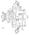
- FIGURE 4 shows the drive link of FIGURE 3 according to one example embodiment.
- drive link 230 may react to at least three types of forces during flapping of rotor system 200. These three types of motion are shown in greater detail in FIGURE 4 : axial stretch, cocking, and torsion.
- drive link 230 features elastomeric material 235 that may react to all three motions simultaneously.
- An elastomeric material is a material, such as a polymer, having the property of viscoelasticity (colloquially, "elasticity").
- An example of an elastomeric material is rubber. Elastomeric materials generally have a low Young's modulus and a high yield strain when compared to other materials.
- Elastomeric materials are typically thermosets having long polymer chains that cross-link during curing (i.e., vulcanizing).
- Use of elastomeric bearing assemblies in a rotor system such as rotor system 110 may create some design issues. For example, using elastomeric materials to react to all three motions shown in FIGURE 4 may result in backside tension in the elastomer, large compressive loads, and/or performance concerns during large amounts of flapping.
- spherical elastomeric bearings as shown in the example of FIGURE 4 , may have limited performance when the bearings are strained in both the torsion and cocking directions, simulatenously.
- teachings of certain embodiments recognize the capability to improve drive link performance by decoupling the cocking and torsion motions.
- teachings of certain embodiments recognize that decoupling the cocking and torsion motions may increase performance in high-flapping tiltrotor systems as well as other tilting and non-tilting rotor systems.
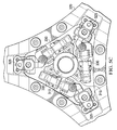
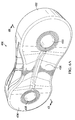
- FIGURE 5A-5D show a drive link 330 according to one example embodiment.
- FIGURE 5A shows a perspective view of drive link 330
- FIGURE 5B shows a cross-section view of drive link 330
- FIGURE 5C shows a top view of drink link 330 installed a rotor system 300
- FIGURE 5D shows a perspective view of drink link 330 installed in rotor system 300.
- drive link receives torque from powerplant 310 via trunions 315 and transfers torque to yoke 320 via drive link couplers 325.
- drive link 330 features bearing housings 332 and 334.
- First bearing housing 332 features a first radial bearing 333
- second bearing housing 334 features a second radial bearing 335.
- first and second radial bearings 333 and 335 may represent elastomeric bearings.
- Drive link 330 also features a coupling member 336 that couples first bearing housing 332 to second bearing housing 334.
- coupling member 336 may allow first bearing housing 332 to move torsionally relative to second bearing housing 334 in response to cocking motions (such as the cocking motions shown in FIGURE 4 ).
- Radial bearings 333 and 335 may allow for torsion motion relative to their respective bearing housings 332 and 334 in response to torsion motions (such as the torsion motions shown in FIGURE 4 ).
- drive link 330 may decouple the cocking and torsion motions by allowing coupling member 336 to respond to cocking motions and radial bearings 333 and 335 to respond to torsion motions.
- axial stiffness may be engineered to produce the most desirable design.
- axial may be a leading contributor to oscillatory drive link loads, and reducing axial stiffness may help decrease oscillatory loads during high flapping.
- providing a separate coupling member 336 to respond to cocking motions may allow radial bearings 333 and 335 to be designed for optimal axial stiffness without needing to respond to cocking motions.
- coupling member 336 represents one example of a conical elastomeric bearing. Teachings of certain embodiments recognize, however, that other coupling members may be used to allow torsion movement between bearing housings 332 and 334.
- a standard roller thrust bearing may be used as a center bearing instead of an elastomeric bearing.
- first bearing housing 332, second bearing housing 334, and coupling member 336 are shown as three separate pieces. Teachings of certain embodiments recognize, however, that drive link 330 may be comprised of more or fewer pieces, and that pieces such as first bearing housing 332, second bearing housing 334, and/or coupling member 336 may be integrated into common components or separated into multiple components.
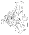
- FIGURE 6A-6C show a drive link 430 according to another example embodiment.
- FIGURE 6A shows a perspective view of drive link 430
- FIGURE 6B shows a cross-section view of drive link 430
- FIGURE 6C shows a perspective view of drink link 430 installed in rotor system 400.
- drive link receives torque from powerplant 410 via trunions 415 and transfers torque to yoke 420 via drive link couplers 425.
- drive link 430 features bearing housings 432 and 434.
- First bearing housing 432 features a first radial bearing 433, and second bearing housing 434 features a second radial bearing 435.
- first and second radial bearings 433 and 435 may represent elastomeric bearings.
- Drive link 430 also features a coupling member 436 that couples first bearing housing 432 to second bearing housing 434.
- first bearing housing 432, second bearing housing 434, and coupling member 436 are shown as a single integrated component.
- first bearing housing 432, second bearing housing 434, and coupling member 436 may, in combination, represent a composite drive link.
- teachings of certain embodiments recognize, however, that drive link 430 may be comprised of more or fewer pieces, and that pieces such as first bearing housing 432, second bearing housing 434, and/or coupling member 436 may be integrated into common components or separated into multiple components.
- coupling member 436 may allow first bearing housing 432 to move torsionally relative to second bearing housing 434 in response to cocking motions (such as the cocking motions shown in FIGURE 4 ).
- Radial bearings 433 and 435 may allow for torsion motion relative to their respective bearing housings 432 and 434 in response to torsion motions (such as the torsion motions shown in FIGURE 4 ).
- drive link 430 may decouple the cocking and torsion motions by allowing coupling member 436 to respond to cocking motions and radial bearings 433 and 435 to respond to torsion motions.
- coupling member 336 represents one example of a flex beam.
- a flex beam is a structural arrangement that allows at least some twisting such that first bearing housing 432 may move torsionally relative to second bearing housing 434 in response to cocking motions.
- the coupling member 436 is shown in a "chicken foot" arrangement.
- the coupling member 436 comprises six flanges 436a-436f.
- each flange 436a-436f may include unidirectional belts and bias packs situated between the unidirectional belts.
- the unidirectional belts are constructed of unidirectional fiberglass material whose fibers are parallel to the spanwise axis, thereby providing high tensile strength.
- the bias pack may be constructed of four plies of +/-45 degree fiberglass material ("bias material"), that is, material whose fibers are at an angle of plus or minus 45 degrees relative to the spanwise axis.
- bias material +/-45 degree fiberglass material
- a thin cover of woven fiberglass material may cover one or more of the flanges in an effort to prevent or localize spanwise cracks in the unidirectional belts.
- flanges 436a-436f may decrease in thickness toward the intersections of the flanges 436a-436f and the web so that only the bias packs meet at the intersections.
- the bias packs of flanges 436b and 436e may intersect the web at an angle of zero degrees
- the bias packs of flanges 436a, 436c, 436d, and 436f may intersect the web a close as practical to an angle of 90 degrees.
- the size of the circles that can be inscribed in the intersections may be minimized, thus minimizing the intersection shear stress developed when the coupling member 436 is twisted.
- example embodiments of the bias packs of flanges 436a and 436f are constructed of four continuous plies of bias material. The same may be true for the bias packs of flanges 436b and 436e and for those of flanges 436c and 436d.
- the bias packs of all the flanges 436a-436f form a web.
- the web may include twelve plies of bias material. Teachings of certain embodiments recognize that the bias packs may provide an efficient means for reacting the shear stress which results from twisting the coupling member 436.
- a thin flange that emanates radially from the neutral feathering axis of the coupling member 436 may offer little resistance to twisting and develop minimum stress when twisted.
- flanges 436b and 436e are radial, while flanges 436a, 436c, 436d, and 436f are only approximately radial. While flanges 436a, 436c, 436d, and 436f being only approximately radial may increase the torsional rigidity of the coupling member 436 and the shear stress developed when the coupling member 436 is twisted, those increases may be minimal, and the configuration shown may provide the appropriate flapping bending rigidity.
- teachings of certain embodiments recognize that, for a given amount of flange material and a given cross-sectional flange width, the greater the number of flanges, the thinner the flanges can be. However, if a flange is too thin, it can buckle when bent edgewise. Increasing the number of flanges that meet at an intersection may increase the size of the circle that can be inscribed in the intersection, which may result in an increase in the intersection shear stress. The increased intersection shear stress, in combination with the other shear stresses to which the intersection may be subjected, can exceed the shear strength of the intersection material, resulting in failure of the flexure at the intersection. Therefore, teachings of certain embodiments recognize the capability to provide more than one intersection, thereby decreasing the intersection shear stress at each intersection.
- the unidirectional belts may be constructed of unidirectional fiberglass material.
- each belt is laid up using thin, 1/8-inch wide, unidirectional fiberglass tape.
- any convenient width tape or a single glass fiber may be used.
- this example embodiment is constructed of fiberglass, teachings of certain embodiments recognize that other high-strength fibers, such as carbon or boron, may be used.
Landscapes
- Engineering & Computer Science (AREA)
- General Engineering & Computer Science (AREA)
- Mechanical Engineering (AREA)
- Aviation & Aerospace Engineering (AREA)
- Manufacturing & Machinery (AREA)
- Support Of The Bearing (AREA)
- Toys (AREA)
- Sliding-Contact Bearings (AREA)
Abstract
Description
- This invention relates generally to tiltrotor aircraft, and more particularly, to a drive link for a tiltrotor rotor system.
- A rotorcraft may include one or more rotor systems. One example of a rotorcraft rotor system is a main rotor system. A main rotor system may generate aerodynamic lift to support the weight of the rotorcraft in flight and thrust to counteract aerodynamic drag and move the rotorcraft in forward flight. Another example of a rotorcraft rotor system is a tail rotor system. A tail rotor system may generate thrust in the same direction as the main rotor system's rotation to counter the torque effect created by the main rotor system.
- Particular embodiments of the present disclosure may provide one or more technical advantages. A technical advantage of one embodiment may include the capability to provide drive links that improve flapping performance. A technical advantage of one embodiment may include the capability to improve drive link performance by decoupling the cocking and torsion motions.
- Certain embodiments of the present disclosure may include some, all, or none of the above advantages. One or more other technical advantages may be readily apparent to those skilled in the art from the figures, descriptions, and claims included herein.
- To provide a more complete understanding of the present invention and the features and advantages thereof, reference is made to the following description taken in conjunction with the accompanying drawings, in which:
-
FIGURE 1 shows a tiltrotor aircraft according to one example embodiment; -
FIGURE 2 shows a simplified example of a rotor system that may be incorporated in whole or in part in the rotorcraft ofFIGURE 1 ; -
FIGURE 3 shows a closer perspective view of a rotor system according to one example embodiment; -
FIGURE 4 shows the drive link of the rotor system ofFIGURE 3 according to one example embodiment; -
FIGURE 5A shows a perspective view of a drive link according to one example embodiment; -
FIGURE 5B shows a cross-section view of the drive link ofFIGURE 5A ; -
FIGURE 5C shows a top view of the drive link ofFIGURE 5A installed in a rotor system; -
FIGURE 5D shows a perspective view of the drive link ofFIGURE 5A installed in a rotor system; -
FIGURE 6A shows a perspective view of a drive link according to another example embodiment; -
FIGURE 6B shows a cross-section view of the drive link ofFIGURE 6A ; and -
FIGURE 6C shows a perspective view of the drive link ofFIGURE 6A installed in a rotor system. -
FIGURE 1 shows arotorcraft 100 according to one example embodiment. Rotorcraft 100 featuresrotor systems blades 120, afuselage 130, alanding gear 140, and awing 150. -
Rotor system 110 may rotateblades 120.Rotor system 110 may include a control system for selectively controlling the pitch of eachblade 120 in order to selectively control direction, thrust, and lift ofrotorcraft 100. In the example ofFIGURE 1 ,rotorcraft 100 represents a tiltrotor aircraft, androtor systems nacelles rotor blades 120, can be selectively controlled in order to selectively control direction, thrust, and lift oftiltrotor aircraft 100. -
Fuselage 130 represents the main body ofrotorcraft 100 and may be coupled to rotor system 110 (e.g., via wing 150) such thatrotor system 110 andblades 120 may movefuselage 130 through the air.Landing gear 140 supportsrotorcraft 100 when rotorcraft 100 is landing and/or when rotorcraft 100 is at rest on the ground. - Teachings of certain embodiments relating to rotor systems described herein may apply to
rotor system 110 and/or other rotor systems, such as non-tilting rotor and helicopter rotor systems. It should also be appreciated that teachings fromrotorcraft 100 may apply to aircraft other than rotorcraft, such as airplanes and unmanned aircraft, to name a few examples. - In the example of
FIGURE 1 ,tiltrotor aircraft 100 may operate in a helicopter mode by tilting the nacelles upright and in an airplane mode by tilting the nacelles forward.Tiltrotor aircraft 100 may generate greater forward speed in airplane mode than in helicopter mode because, in airplane mode,blades 120 are oriented to generate greater thrust propelling the aircraft forward (somewhat analogous to a propeller). -
FIGURE 2 shows a simplified example of arotor system 110 that may be incorporated in whole or in part in therotorcraft 100 ofFIGURE 1 . In the example ofFIGURE 2 ,rotor system 110 features a power train 112, ayoke 114, aswashplate 116, andpitch links 118. In some examples,rotor system 110 may include more or fewer components. For example,FIGURE 2 does not show components such as a gearbox, drive links, drive levers, tilting devices, and other components that may be incorporated. - Power train 112 features a
power source 112a and a drive shaft112b. Power source 112a,drive shaft 112b, andyoke 114 are mechanical components for transmitting torque and/or rotation. Power train 112 may include a variety of components, including an engine, a transmission, and differentials. In operation,drive shaft 112b receives torque or rotational energy frompower source 112a and rotatesyoke 114. Rotation ofrotor yoke 114 causesblades 120 to rotate aboutdrive shaft 112b. In some embodiments, power train 112 may include more or fewer components. For example, in some embodiments, tilting devices may be provided in mechanical communication with power train 112 that allows certain components ofrotor system 110 to tilt between helicopter mode and airplane mode. - Swashplate 116 translates rotorcraft flight control input into motion of
blades 120. Becauseblades 120 are typically spinning when the rotorcraft is in flight,swashplate 116 may transmit flight control input from the non-rotating fuselage to theyoke 114,blades 120, and/orcomponents coupling yoke 114 to blades 120 (e.g., grips and pitch horns). References in this description to coupling between a pitch link and a yoke may also include, but are not limited to, coupling between a pitch link and a blade or components coupling a yoke to a blade. - In some examples,
swashplate 116 may include anon-rotating swashplate ring 116a and a rotatingswashplate ring 116b. Non-rotatingswashplate ring 116a does not rotate withdrive shaft 112b, whereas rotatingswashplate ring 116b does rotate withdrive shaft 112b. In the example ofFIGURE 2 ,pitch links 118 connect rotatingswashplate ring 116b toblades 120. - In operation, according to one example embodiment, translating the
non-rotating swashplate ring 116a along the axis ofdrive shaft 112b causes thepitch links 118 to move up or down. This changes the pitch angle of allblades 120 equally, increasing or decreasing the thrust of the rotor and causing the aircraft to ascend or descend. Tilting thenon-rotating swashplate ring 116a causes the rotatingswashplate 116b to tilt, moving thepitch links 118 up and down cyclically as they rotate with the drive shaft. This tilts the thrust vector of the rotor, causingrotorcraft 100 to translate horizontally following the direction the swashplate is tilted. - During operation,
rotor system 110 may be subject to a variety of forces. As one example, the weight ofblades 120 and the lift ofblades 120 may result in transverse forces onyoke 114 and other components. Two examples of transverse forces may include forces resulting from flapping and coning ofblades 120. Flapping may generally refer to the up-and-down movement of a rotor blade positioned at a right angle to the plane of rotation. Coning may generally refer to the upward flexing of a rotor blade due to lift forces acting on the rotor blade. - As another example,
rotor system 110 may be subject to other forces, such as axial, lead/lag, and feathering forces. Axial forces may general refer to forces onrotor system 110 resulting from the centrifugal force on the rotor blades during rotation of the rotor blades. Lead and lag forces may generally refer to forces resulting from the horizontal movement of rotor blades about a vertical pin. Lead and lag forces may occur, for example, ifblades 120 do not rotate faster or slower than the rotation ofyoke 114. Feathering forces may generally refer to forces resulting from twisting motions that cause a rotor blade to change pitch. - Such forces may cause damage to
rotor system 110 during operation if, for example, the magnitude of the forces is too high or the motions causing such forces occur too frequently. For example, damage may occur as the result of rotor flapping relative to the mast. Accordingly, teachings of certain embodiments recognize the capability to provide drive links that may transfer torque from the mast to the rotor blades while still allowing at least some rotor system flapping. -
FIGURE 3 shows a perspective view of arotor system 200 according to one example embodiment. In the example ofFIGURE 3 ,rotor system 200 features apowerplant 210, ayoke 220, and drivelinks 230. In operation, according to one example embodiment, drivelinks 230 are in mechanical communication withpowerplant 210 andyoke 220 and transfers torque frompowerplant 210 toyoke 220 while still allowing at least some rotor system flapping ofyoke 220 relative topowerplant 210.FIGURE 4 shows the drive link ofFIGURE 3 according to one example embodiment. - In operation, according to one example embodiment,
drive link 230 may react to at least three types of forces during flapping ofrotor system 200. These three types of motion are shown in greater detail inFIGURE 4 : axial stretch, cocking, and torsion. In the example ofFIGURE 4 ,drive link 230 featureselastomeric material 235 that may react to all three motions simultaneously. An elastomeric material is a material, such as a polymer, having the property of viscoelasticity (colloquially, "elasticity"). An example of an elastomeric material is rubber. Elastomeric materials generally have a low Young's modulus and a high yield strain when compared to other materials. Elastomeric materials are typically thermosets having long polymer chains that cross-link during curing (i.e., vulcanizing). Use of elastomeric bearing assemblies in a rotor system such asrotor system 110, however, may create some design issues. For example, using elastomeric materials to react to all three motions shown inFIGURE 4 may result in backside tension in the elastomer, large compressive loads, and/or performance concerns during large amounts of flapping. In addition, spherical elastomeric bearings, as shown in the example ofFIGURE 4 , may have limited performance when the bearings are strained in both the torsion and cocking directions, simulatenously. - Accordingly, teachings of certain embodiments recognize the capability to improve drive link performance by decoupling the cocking and torsion motions. Teachings of certain embodiments recognize that decoupling the cocking and torsion motions may increase performance in high-flapping tiltrotor systems as well as other tilting and non-tilting rotor systems.
-
FIGURE 5A-5D show adrive link 330 according to one example embodiment.FIGURE 5A shows a perspective view ofdrive link 330,FIGURE 5B shows a cross-section view ofdrive link 330,FIGURE 5C shows a top view ofdrink link 330 installed a rotor system 300, andFIGURE 5D shows a perspective view ofdrink link 330 installed in rotor system 300. In operation, according to one example embodiment, drive link receives torque frompowerplant 310 viatrunions 315 and transfers torque toyoke 320 viadrive link couplers 325. - As seen in the example of
FIGURES 5A and 5B ,drive link 330features bearing housings housing 332 features a firstradial bearing 333, andsecond bearing housing 334 features a secondradial bearing 335. In the example ofFIGURES 5A and 5B , first and secondradial bearings -
Drive link 330 also features a coupling member 336 that couples first bearinghousing 332 tosecond bearing housing 334. In operation, according to one example embodiment, coupling member 336 may allow first bearinghousing 332 to move torsionally relative tosecond bearing housing 334 in response to cocking motions (such as the cocking motions shown inFIGURE 4 ).Radial bearings respective bearing housings FIGURE 4 ). In this manner,drive link 330 may decouple the cocking and torsion motions by allowing coupling member 336 to respond to cocking motions andradial bearings - Teachings of certain embodiments recognize that decoupling the cocking and torsion motions in
drive link 330 may allow the axial stiffness to be engineered to produce the most desirable design. For example, axial may be a leading contributor to oscillatory drive link loads, and reducing axial stiffness may help decrease oscillatory loads during high flapping. Teachings of certain embodiments recognize that providing a separate coupling member 336 to respond to cocking motions may allowradial bearings - In the example of
FIGURES 5A and 5B , coupling member 336 represents one example of a conical elastomeric bearing. Teachings of certain embodiments recognize, however, that other coupling members may be used to allow torsion movement between bearinghousings - In the example of
FIGURES 5A and 5B , first bearinghousing 332, second bearinghousing 334, and coupling member 336 are shown as three separate pieces. Teachings of certain embodiments recognize, however, thatdrive link 330 may be comprised of more or fewer pieces, and that pieces such as first bearinghousing 332, second bearinghousing 334, and/or coupling member 336 may be integrated into common components or separated into multiple components. -
FIGURE 6A-6C show adrive link 430 according to another example embodiment.FIGURE 6A shows a perspective view ofdrive link 430,FIGURE 6B shows a cross-section view ofdrive link 430, andFIGURE 6C shows a perspective view ofdrink link 430 installed in rotor system 400. In operation, according to one example embodiment, drive link receives torque frompowerplant 410 viatrunions 415 and transfers torque toyoke 420 viadrive link couplers 425. - As seen in the example of
FIGURES 6A and6B ,drive link 430features bearing housings housing 432 features a firstradial bearing 433, andsecond bearing housing 434 features a secondradial bearing 435. In the example ofFIGURES 6A and6B , first and secondradial bearings -
Drive link 430 also features acoupling member 436 that couples first bearinghousing 432 tosecond bearing housing 434. In the example ofFIGURES 6A and6B , first bearinghousing 432, second bearinghousing 434, andcoupling member 436 are shown as a single integrated component. For example, first bearinghousing 432, second bearinghousing 434, andcoupling member 436 may, in combination, represent a composite drive link. Teachings of certain embodiments recognize, however, thatdrive link 430 may be comprised of more or fewer pieces, and that pieces such as first bearinghousing 432, second bearinghousing 434, and/orcoupling member 436 may be integrated into common components or separated into multiple components. - In operation, according to one example embodiment,
coupling member 436 may allow first bearinghousing 432 to move torsionally relative tosecond bearing housing 434 in response to cocking motions (such as the cocking motions shown inFIGURE 4 ).Radial bearings respective bearing housings FIGURE 4 ). In this manner,drive link 430 may decouple the cocking and torsion motions by allowingcoupling member 436 to respond to cocking motions andradial bearings - In the example of
FIGURES 6A and6B , coupling member 336 represents one example of a flex beam. A flex beam is a structural arrangement that allows at least some twisting such that first bearinghousing 432 may move torsionally relative tosecond bearing housing 434 in response to cocking motions. - In the example of
FIGURES 6A and6B , thecoupling member 436 is shown in a "chicken foot" arrangement. In this example embodiment, thecoupling member 436 comprises sixflanges 436a-436f. - In some embodiments, each
flange 436a-436f may include unidirectional belts and bias packs situated between the unidirectional belts. In one example embodiment, the unidirectional belts are constructed of unidirectional fiberglass material whose fibers are parallel to the spanwise axis, thereby providing high tensile strength. In this example embodiment, the bias pack may be constructed of four plies of +/-45 degree fiberglass material ("bias material"), that is, material whose fibers are at an angle of plus or minus 45 degrees relative to the spanwise axis. A thin cover of woven fiberglass material may cover one or more of the flanges in an effort to prevent or localize spanwise cracks in the unidirectional belts. - In some embodiments,
flanges 436a-436f may decrease in thickness toward the intersections of theflanges 436a-436f and the web so that only the bias packs meet at the intersections. In addition, the bias packs offlanges flanges flanges 436a-436f at the intersections and the angles at which theflanges 436a-436f intersect the web 73, the size of the circles that can be inscribed in the intersections may be minimized, thus minimizing the intersection shear stress developed when thecoupling member 436 is twisted. - As stated above, example embodiments of the bias packs of
flanges flanges flanges flanges 436a-436f form a web. Thus, the web may include twelve plies of bias material. Teachings of certain embodiments recognize that the bias packs may provide an efficient means for reacting the shear stress which results from twisting thecoupling member 436. - In some embodiments, a thin flange that emanates radially from the neutral feathering axis of the
coupling member 436 may offer little resistance to twisting and develop minimum stress when twisted. In the example ofFIGURES 5A and 5B ,flanges flanges flanges coupling member 436 and the shear stress developed when thecoupling member 436 is twisted, those increases may be minimal, and the configuration shown may provide the appropriate flapping bending rigidity. - Teachings of certain embodiments recognize that, for a given amount of flange material and a given cross-sectional flange width, the greater the number of flanges, the thinner the flanges can be. However, if a flange is too thin, it can buckle when bent edgewise. Increasing the number of flanges that meet at an intersection may increase the size of the circle that can be inscribed in the intersection, which may result in an increase in the intersection shear stress. The increased intersection shear stress, in combination with the other shear stresses to which the intersection may be subjected, can exceed the shear strength of the intersection material, resulting in failure of the flexure at the intersection. Therefore, teachings of certain embodiments recognize the capability to provide more than one intersection, thereby decreasing the intersection shear stress at each intersection.
- As mentioned above, the unidirectional belts may be constructed of unidirectional fiberglass material. In one example embodiment, each belt is laid up using thin, 1/8-inch wide, unidirectional fiberglass tape. Alternatively, any convenient width tape or a single glass fiber may be used. Although, this example embodiment is constructed of fiberglass, teachings of certain embodiments recognize that other high-strength fibers, such as carbon or boron, may be used.
- Modifications, additions, or omissions may be made to the systems and apparatuses described herein without departing from the scope of the invention. The components of the systems and apparatuses may be integrated or separated. Moreover, the operations of the systems and apparatuses may be performed by more, fewer, or other components. The methods may include more, fewer, or other steps. Additionally, steps may be performed in any suitable order.
- Although several embodiments have been illustrated and described in detail, it will be recognized that substitutions and alterations are possible without departing from the spirit and scope of the present invention, as defined by the appended claims.
- To aid the Patent Office, and any readers of any patent issued on this application in interpreting the claims appended hereto, applicants wish to note that they do not intend any of the appended claims to invoke paragraph 6 of 35 U.S.C. § 112 as it exists on the date of filing hereof unless the words "means for" or "step for" are explicitly used in the particular claim.
Claims (14)
- A tiltrotor aircraft, comprising:a body;a wing member;a power train coupled to the body and comprising a power source and a drive shaft in mechanical communication with the power source; anda rotor system coupled to the wing member and in mechanical communication with the drive shaft, at least part of the rotor system being tiltable between a helicopter mode position and an airplane mode position, the rotor system comprising:a first drive element in mechanical communication with the drive shaft;a yoke disposed at least partially about the drive shaft;a second drive element in mechanical communication with the yoke;a rotor blade coupled to the yoke; anda drive link coupled between the drive shaft and the yoke, the drive link comprising:a first bearing housing defining an opening therethrough configured to receive the first drive element;a first radial bearing disposed between an inner surface of the opening of the first bearing housing and an outer surface of the first drive element;a second bearing housing defining an opening therethrough configured to receive the second drive element;a second radial bearing disposed between an inner surface of the opening of the second bearing housing and an outer surface of the second drive element; anda central portion coupled between the first bearing housing and the second bearing housing, the central portion having less torsional stiffness than the first and second bearing housings such that the central portion twists in response to cocking of the first bearing housing relative to the second bearing housing.
- A drive link, comprising:a first bearing housing defining an opening therethrough configured to receive a first drive element;a first radial bearing disposed between an inner surface of the opening of the first bearing housing and an outer surface of the first drive element;a second bearing housing defining an opening therethrough configured to receive a second drive element;a second radial bearing disposed between an inner surface of the opening of the second bearing housing and an outer surface of the second drive element; anda central portion coupled between the first bearing housing and the second bearing housing, the central portion having less torsional stiffness than the first and second bearing housings such that the central portion twists in response to cocking of the first bearing housing relative to the second bearing housing.
- The tiltrotor aircraft of claim 1 or the drive link of claim 2, wherein:the first bearing housing, the opening of the first bearing housing, the second bearing housing, the opening of the second bearing housing, and the central portion are coaxial along a drive link axis; andthe central portion has less torsional stiffness relative to the drive link axis than the first and second bearing housings.
- The tiltrotor aircraft or drive link of claim 3, wherein the central portion has less torsional stiffness relative to the drive link axis than the first and second radial bearings.
- The tiltrotor of claim 1 or of any preceding claim, or the drive link of claim 2 or of any preceding claim, the central portion comprising:a central element in mechanical communication with the first bearing housing;a central bearing housing in mechanical communication with the second bearing housing, the central bearing housing defining an opening therethrough configured to receive the central element; anda central radial bearing disposed between an inner surface of the opening of the central bearing housing and an outer surface of the central element.
- The tiltrotor or drive link of claim 5, the central radial bearing comprising an elastomeric bearing.
- The tiltrotor or drive link of claim 5, the central radial bearing comprising a roller thrust bearing.
- The tiltrotor of claim 1 or of any preceding claim, or the drive link of claim 2 or of any preceding claim, the central portion comprising a composite flex beam.
- A method of transmitting torque from a drive shaft to a rotor yoke, the method comprising:receiving, at a first bearing housing opening, a first drive element in mechanical communication with the drive shaft;receiving, at a second bearing housing opening, a second drive element in mechanical communication with the rotor yoke;providing a central portion coupled between the first and second bearing housings; andallowing twisting of the central portion in response to cocking of the first bearing housing relative to the second bearing housing.
- The method of claim 9, further comprising providing:a first radial bearing disposed between an inner surface of the opening of the first bearing housing and an outer surface of the first drive element; anda second radial bearing disposed between an inner surface of the opening of the second bearing housing and an outer surface of the second drive element.
- The method of claim 9 or of claim 10, the central portion comprising:a central element in mechanical communication with the first bearing housing;a central bearing housing in mechanical communication with the second bearing housing, the central bearing housing defining an opening therethrough configured to receive the central element; anda central radial bearing disposed between an inner surface of the opening of the central bearing housing and an outer surface of the central element.
- The method of claim 11, the central radial bearing comprising an elastomeric bearing.
- The method of claim 11, the central radial bearing comprising a roller thrust bearing.
- The method of claim 9 or of any preceding method claim, the central portion comprising a composite flex beam.
Applications Claiming Priority (1)
| Application Number | Priority Date | Filing Date | Title |
|---|---|---|---|
| US14/069,425 US9657816B2 (en) | 2013-11-01 | 2013-11-01 | Drive link for tiltrotor rotor system |
Publications (2)
| Publication Number | Publication Date |
|---|---|
| EP2868576A1 true EP2868576A1 (en) | 2015-05-06 |
| EP2868576B1 EP2868576B1 (en) | 2016-03-30 |
Family
ID=49885146
Family Applications (1)
| Application Number | Title | Priority Date | Filing Date |
|---|---|---|---|
| EP14150195.7A Active EP2868576B1 (en) | 2013-11-01 | 2014-01-06 | Drive link for tiltrotor rotor system |
Country Status (2)
| Country | Link |
|---|---|
| US (1) | US9657816B2 (en) |
| EP (1) | EP2868576B1 (en) |
Cited By (1)
| Publication number | Priority date | Publication date | Assignee | Title |
|---|---|---|---|---|
| EP3421361A1 (en) * | 2017-06-28 | 2019-01-02 | Bell Helicopter Textron Inc. | Articulated rotor systems with pitch independent damping |
Families Citing this family (7)
| Publication number | Priority date | Publication date | Assignee | Title |
|---|---|---|---|---|
| USD808328S1 (en) | 2016-09-14 | 2018-01-23 | Bell Helicopter Textron Inc. | Foldable tiltrotor aircraft |
| US10597150B2 (en) | 2018-04-24 | 2020-03-24 | Textron Innovations Inc. | Articulated rotor systems with blade-to-blade damping |
| USD909949S1 (en) | 2018-11-15 | 2021-02-09 | Bell Helicopter Textron Inc. | Tiltrotor aircraft |
| USD974276S1 (en) * | 2018-11-15 | 2023-01-03 | Textron Innovations, Inc. | Aircraft spinner |
| USD974277S1 (en) | 2018-11-15 | 2023-01-03 | Textron Innovations, Inc. | Aircraft payload enclosure |
| USD909278S1 (en) | 2018-11-15 | 2021-02-02 | Bell Helicopter Textron Inc. | Foldable tiltrotor aircraft |
| DE102020130067A1 (en) | 2020-11-13 | 2022-05-19 | Vibracoustic Se | Device for supporting an intermediate shaft of a transmission |
Citations (6)
| Publication number | Priority date | Publication date | Assignee | Title |
|---|---|---|---|---|
| EP0306027A2 (en) * | 1987-09-04 | 1989-03-08 | Barry Wright Corporation | Laminated bearing |
| US4986735A (en) * | 1989-10-13 | 1991-01-22 | Bell Helicopter Textron, Inc. | Pitch change bearing system |
| US5186686A (en) * | 1990-05-11 | 1993-02-16 | Lord Corporation | Link and bearing for rotary coupling |
| US20030223871A1 (en) * | 2002-05-30 | 2003-12-04 | Schmaling David N. | Snubber-vibration damper system for a bearingless main rotor |
| US20080267778A1 (en) * | 2005-11-30 | 2008-10-30 | Stamps Frank B | Torque Coupling for Rotary-Wing Aircraft |
| WO2010082936A1 (en) * | 2009-01-19 | 2010-07-22 | Bell Helicopter Textron Inc. | Stiff-in-plane rotor configuration |
Family Cites Families (9)
| Publication number | Priority date | Publication date | Assignee | Title |
|---|---|---|---|---|
| US4804352A (en) * | 1987-01-30 | 1989-02-14 | Lord Corporation | Link-type rotary coupling |
| US5358381A (en) | 1993-03-19 | 1994-10-25 | Bell Helicopter Textron Inc. | Yoke for helicopter rotor systems |
| US6296444B1 (en) * | 1999-10-01 | 2001-10-02 | Bell Helicopter Textron Inc. | Prop rotor hub |
| EP1888930B1 (en) * | 2005-06-07 | 2012-10-10 | Bell Helicopter Textron Inc. | Improved constant-velocity joint for tiltrotor hubs |
| WO2008091376A2 (en) * | 2006-07-25 | 2008-07-31 | Lord Corporation | Tiltrotor aircraft drivelink |
| US10377477B2 (en) * | 2011-12-28 | 2019-08-13 | Bell Helicopter Textron Inc. | Adjustable pitch link |
| US8961325B2 (en) * | 2013-03-13 | 2015-02-24 | Bell Helicopter Textron Inc. | Rotor hub elastomeric bearings |
| US9074638B2 (en) * | 2013-03-14 | 2015-07-07 | Bell Helicopter Textron Inc. | Multilink constant velocity joint |
| US9994311B2 (en) * | 2013-04-29 | 2018-06-12 | Bell Helicopter Textron Inc. | Constant-velocity joint link with reduced axial stiffness |
-
2013
- 2013-11-01 US US14/069,425 patent/US9657816B2/en active Active
-
2014
- 2014-01-06 EP EP14150195.7A patent/EP2868576B1/en active Active
Patent Citations (6)
| Publication number | Priority date | Publication date | Assignee | Title |
|---|---|---|---|---|
| EP0306027A2 (en) * | 1987-09-04 | 1989-03-08 | Barry Wright Corporation | Laminated bearing |
| US4986735A (en) * | 1989-10-13 | 1991-01-22 | Bell Helicopter Textron, Inc. | Pitch change bearing system |
| US5186686A (en) * | 1990-05-11 | 1993-02-16 | Lord Corporation | Link and bearing for rotary coupling |
| US20030223871A1 (en) * | 2002-05-30 | 2003-12-04 | Schmaling David N. | Snubber-vibration damper system for a bearingless main rotor |
| US20080267778A1 (en) * | 2005-11-30 | 2008-10-30 | Stamps Frank B | Torque Coupling for Rotary-Wing Aircraft |
| WO2010082936A1 (en) * | 2009-01-19 | 2010-07-22 | Bell Helicopter Textron Inc. | Stiff-in-plane rotor configuration |
Cited By (1)
| Publication number | Priority date | Publication date | Assignee | Title |
|---|---|---|---|---|
| EP3421361A1 (en) * | 2017-06-28 | 2019-01-02 | Bell Helicopter Textron Inc. | Articulated rotor systems with pitch independent damping |
Also Published As
| Publication number | Publication date |
|---|---|
| EP2868576B1 (en) | 2016-03-30 |
| US9657816B2 (en) | 2017-05-23 |
| US20150122953A1 (en) | 2015-05-07 |
Similar Documents
| Publication | Publication Date | Title |
|---|---|---|
| EP2832640B1 (en) | Composite flexure for tiltrotor rotor system | |
| US10392098B2 (en) | High stiffness hub assemblies for rotor systems | |
| EP2868576B1 (en) | Drive link for tiltrotor rotor system | |
| EP3333074B1 (en) | Soft-in-plane proprotor systems | |
| EP2604513B1 (en) | Blade-pitch control system with feedback lever | |
| US9254915B2 (en) | Rotor system with torque-splitter assembly | |
| EP3421361B1 (en) | Articulated rotor systems with pitch independent damping | |
| EP3533710B1 (en) | A passive pitch angle adjustment apparatus | |
| US10793254B2 (en) | Soft-in-plane proprotor systems | |
| US9701403B2 (en) | Broad goods composite yoke for rotor system | |
| EP3323720B1 (en) | Proprotor systems for tiltrotor aircraft | |
| US10654558B2 (en) | Rotor hub with enforced collective coning | |
| US20180162526A1 (en) | Proprotor Systems for Tiltrotor Aircraft | |
| JP4112870B2 (en) | Aircraft constant speed transmission rotor | |
| US10518867B2 (en) | Loop yoke for proprotor systems | |
| US5042967A (en) | Drive shaft and rotor hub for helicopter flexible rotor system | |
| US10514060B2 (en) | Inboard bearing assemblies with anti-rotation features | |
| EP3575211A1 (en) | Rotor assembly with right lock-number blades | |
| US10597150B2 (en) | Articulated rotor systems with blade-to-blade damping | |
| US11440651B1 (en) | Spherical bearing centrifugal force retention link | |
| EP3385161B1 (en) | Teetering tail rotor yoke |
Legal Events
| Date | Code | Title | Description |
|---|---|---|---|
| PUAI | Public reference made under article 153(3) epc to a published international application that has entered the european phase |
Free format text: ORIGINAL CODE: 0009012 |
|
| 17P | Request for examination filed |
Effective date: 20140106 |
|
| AK | Designated contracting states |
Kind code of ref document: A1 Designated state(s): AL AT BE BG CH CY CZ DE DK EE ES FI FR GB GR HR HU IE IS IT LI LT LU LV MC MK MT NL NO PL PT RO RS SE SI SK SM TR |
|
| AX | Request for extension of the european patent |
Extension state: BA ME |
|
| RIC1 | Information provided on ipc code assigned before grant |
Ipc: F16D 3/62 20060101ALI20151007BHEP Ipc: B64C 27/35 20060101ALI20151007BHEP Ipc: F16F 1/393 20060101ALI20151007BHEP Ipc: F16H 21/00 20060101ALI20151007BHEP Ipc: F16F 1/387 20060101ALI20151007BHEP Ipc: B64C 27/33 20060101ALI20151007BHEP Ipc: F16C 19/30 20060101ALI20151007BHEP Ipc: B64C 29/00 20060101AFI20151007BHEP Ipc: F16C 27/06 20060101ALI20151007BHEP |
|
| GRAP | Despatch of communication of intention to grant a patent |
Free format text: ORIGINAL CODE: EPIDOSNIGR1 |
|
| INTG | Intention to grant announced |
Effective date: 20151123 |
|
| GRAS | Grant fee paid |
Free format text: ORIGINAL CODE: EPIDOSNIGR3 |
|
| GRAA | (expected) grant |
Free format text: ORIGINAL CODE: 0009210 |
|
| AK | Designated contracting states |
Kind code of ref document: B1 Designated state(s): AL AT BE BG CH CY CZ DE DK EE ES FI FR GB GR HR HU IE IS IT LI LT LU LV MC MK MT NL NO PL PT RO RS SE SI SK SM TR |
|
| REG | Reference to a national code |
Ref country code: GB Ref legal event code: FG4D |
|
| REG | Reference to a national code |
Ref country code: CH Ref legal event code: EP |
|
| REG | Reference to a national code |
Ref country code: AT Ref legal event code: REF Ref document number: 785073 Country of ref document: AT Kind code of ref document: T Effective date: 20160415 |
|
| REG | Reference to a national code |
Ref country code: IE Ref legal event code: FG4D |
|
| REG | Reference to a national code |
Ref country code: DE Ref legal event code: R096 Ref document number: 602014001227 Country of ref document: DE |
|
| REG | Reference to a national code |
Ref country code: LT Ref legal event code: MG4D |
|
| PG25 | Lapsed in a contracting state [announced via postgrant information from national office to epo] |
Ref country code: GR Free format text: LAPSE BECAUSE OF FAILURE TO SUBMIT A TRANSLATION OF THE DESCRIPTION OR TO PAY THE FEE WITHIN THE PRESCRIBED TIME-LIMIT Effective date: 20160701 Ref country code: HR Free format text: LAPSE BECAUSE OF FAILURE TO SUBMIT A TRANSLATION OF THE DESCRIPTION OR TO PAY THE FEE WITHIN THE PRESCRIBED TIME-LIMIT Effective date: 20160330 Ref country code: NO Free format text: LAPSE BECAUSE OF FAILURE TO SUBMIT A TRANSLATION OF THE DESCRIPTION OR TO PAY THE FEE WITHIN THE PRESCRIBED TIME-LIMIT Effective date: 20160630 Ref country code: FI Free format text: LAPSE BECAUSE OF FAILURE TO SUBMIT A TRANSLATION OF THE DESCRIPTION OR TO PAY THE FEE WITHIN THE PRESCRIBED TIME-LIMIT Effective date: 20160330 |
|
| REG | Reference to a national code |
Ref country code: NL Ref legal event code: MP Effective date: 20160330 |
|
| REG | Reference to a national code |
Ref country code: AT Ref legal event code: MK05 Ref document number: 785073 Country of ref document: AT Kind code of ref document: T Effective date: 20160330 |
|
| PG25 | Lapsed in a contracting state [announced via postgrant information from national office to epo] |
Ref country code: RS Free format text: LAPSE BECAUSE OF FAILURE TO SUBMIT A TRANSLATION OF THE DESCRIPTION OR TO PAY THE FEE WITHIN THE PRESCRIBED TIME-LIMIT Effective date: 20160330 Ref country code: LV Free format text: LAPSE BECAUSE OF FAILURE TO SUBMIT A TRANSLATION OF THE DESCRIPTION OR TO PAY THE FEE WITHIN THE PRESCRIBED TIME-LIMIT Effective date: 20160330 Ref country code: LT Free format text: LAPSE BECAUSE OF FAILURE TO SUBMIT A TRANSLATION OF THE DESCRIPTION OR TO PAY THE FEE WITHIN THE PRESCRIBED TIME-LIMIT Effective date: 20160330 Ref country code: SE Free format text: LAPSE BECAUSE OF FAILURE TO SUBMIT A TRANSLATION OF THE DESCRIPTION OR TO PAY THE FEE WITHIN THE PRESCRIBED TIME-LIMIT Effective date: 20160330 |
|
| PG25 | Lapsed in a contracting state [announced via postgrant information from national office to epo] |
Ref country code: NL Free format text: LAPSE BECAUSE OF FAILURE TO SUBMIT A TRANSLATION OF THE DESCRIPTION OR TO PAY THE FEE WITHIN THE PRESCRIBED TIME-LIMIT Effective date: 20160330 |
|
| PG25 | Lapsed in a contracting state [announced via postgrant information from national office to epo] |
Ref country code: IS Free format text: LAPSE BECAUSE OF FAILURE TO SUBMIT A TRANSLATION OF THE DESCRIPTION OR TO PAY THE FEE WITHIN THE PRESCRIBED TIME-LIMIT Effective date: 20160730 Ref country code: EE Free format text: LAPSE BECAUSE OF FAILURE TO SUBMIT A TRANSLATION OF THE DESCRIPTION OR TO PAY THE FEE WITHIN THE PRESCRIBED TIME-LIMIT Effective date: 20160330 Ref country code: PL Free format text: LAPSE BECAUSE OF FAILURE TO SUBMIT A TRANSLATION OF THE DESCRIPTION OR TO PAY THE FEE WITHIN THE PRESCRIBED TIME-LIMIT Effective date: 20160330 |
|
| PG25 | Lapsed in a contracting state [announced via postgrant information from national office to epo] |
Ref country code: ES Free format text: LAPSE BECAUSE OF FAILURE TO SUBMIT A TRANSLATION OF THE DESCRIPTION OR TO PAY THE FEE WITHIN THE PRESCRIBED TIME-LIMIT Effective date: 20160330 Ref country code: AT Free format text: LAPSE BECAUSE OF FAILURE TO SUBMIT A TRANSLATION OF THE DESCRIPTION OR TO PAY THE FEE WITHIN THE PRESCRIBED TIME-LIMIT Effective date: 20160330 Ref country code: SK Free format text: LAPSE BECAUSE OF FAILURE TO SUBMIT A TRANSLATION OF THE DESCRIPTION OR TO PAY THE FEE WITHIN THE PRESCRIBED TIME-LIMIT Effective date: 20160330 Ref country code: PT Free format text: LAPSE BECAUSE OF FAILURE TO SUBMIT A TRANSLATION OF THE DESCRIPTION OR TO PAY THE FEE WITHIN THE PRESCRIBED TIME-LIMIT Effective date: 20160801 Ref country code: SM Free format text: LAPSE BECAUSE OF FAILURE TO SUBMIT A TRANSLATION OF THE DESCRIPTION OR TO PAY THE FEE WITHIN THE PRESCRIBED TIME-LIMIT Effective date: 20160330 Ref country code: CZ Free format text: LAPSE BECAUSE OF FAILURE TO SUBMIT A TRANSLATION OF THE DESCRIPTION OR TO PAY THE FEE WITHIN THE PRESCRIBED TIME-LIMIT Effective date: 20160330 Ref country code: RO Free format text: LAPSE BECAUSE OF FAILURE TO SUBMIT A TRANSLATION OF THE DESCRIPTION OR TO PAY THE FEE WITHIN THE PRESCRIBED TIME-LIMIT Effective date: 20160330 |
|
| PG25 | Lapsed in a contracting state [announced via postgrant information from national office to epo] |
Ref country code: BE Free format text: LAPSE BECAUSE OF FAILURE TO SUBMIT A TRANSLATION OF THE DESCRIPTION OR TO PAY THE FEE WITHIN THE PRESCRIBED TIME-LIMIT Effective date: 20160330 |
|
| REG | Reference to a national code |
Ref country code: DE Ref legal event code: R097 Ref document number: 602014001227 Country of ref document: DE |
|
| REG | Reference to a national code |
Ref country code: FR Ref legal event code: PLFP Year of fee payment: 4 |
|
| PG25 | Lapsed in a contracting state [announced via postgrant information from national office to epo] |
Ref country code: DK Free format text: LAPSE BECAUSE OF FAILURE TO SUBMIT A TRANSLATION OF THE DESCRIPTION OR TO PAY THE FEE WITHIN THE PRESCRIBED TIME-LIMIT Effective date: 20160330 |
|
| PLBE | No opposition filed within time limit |
Free format text: ORIGINAL CODE: 0009261 |
|
| STAA | Information on the status of an ep patent application or granted ep patent |
Free format text: STATUS: NO OPPOSITION FILED WITHIN TIME LIMIT |
|
| 26N | No opposition filed |
Effective date: 20170103 |
|
| PG25 | Lapsed in a contracting state [announced via postgrant information from national office to epo] |
Ref country code: SI Free format text: LAPSE BECAUSE OF FAILURE TO SUBMIT A TRANSLATION OF THE DESCRIPTION OR TO PAY THE FEE WITHIN THE PRESCRIBED TIME-LIMIT Effective date: 20160330 |
|
| REG | Reference to a national code |
Ref country code: CH Ref legal event code: PL |
|
| PG25 | Lapsed in a contracting state [announced via postgrant information from national office to epo] |
Ref country code: MC Free format text: LAPSE BECAUSE OF FAILURE TO SUBMIT A TRANSLATION OF THE DESCRIPTION OR TO PAY THE FEE WITHIN THE PRESCRIBED TIME-LIMIT Effective date: 20160330 |
|
| PG25 | Lapsed in a contracting state [announced via postgrant information from national office to epo] |
Ref country code: CH Free format text: LAPSE BECAUSE OF NON-PAYMENT OF DUE FEES Effective date: 20170131 Ref country code: LI Free format text: LAPSE BECAUSE OF NON-PAYMENT OF DUE FEES Effective date: 20170131 |
|
| REG | Reference to a national code |
Ref country code: IE Ref legal event code: MM4A |
|
| PG25 | Lapsed in a contracting state [announced via postgrant information from national office to epo] |
Ref country code: LU Free format text: LAPSE BECAUSE OF NON-PAYMENT OF DUE FEES Effective date: 20170106 |
|
| REG | Reference to a national code |
Ref country code: FR Ref legal event code: PLFP Year of fee payment: 5 |
|
| PG25 | Lapsed in a contracting state [announced via postgrant information from national office to epo] |
Ref country code: IE Free format text: LAPSE BECAUSE OF NON-PAYMENT OF DUE FEES Effective date: 20170106 |
|
| PG25 | Lapsed in a contracting state [announced via postgrant information from national office to epo] |
Ref country code: MT Free format text: LAPSE BECAUSE OF NON-PAYMENT OF DUE FEES Effective date: 20170106 |
|
| PG25 | Lapsed in a contracting state [announced via postgrant information from national office to epo] |
Ref country code: AL Free format text: LAPSE BECAUSE OF FAILURE TO SUBMIT A TRANSLATION OF THE DESCRIPTION OR TO PAY THE FEE WITHIN THE PRESCRIBED TIME-LIMIT Effective date: 20160330 |
|
| PG25 | Lapsed in a contracting state [announced via postgrant information from national office to epo] |
Ref country code: HU Free format text: LAPSE BECAUSE OF FAILURE TO SUBMIT A TRANSLATION OF THE DESCRIPTION OR TO PAY THE FEE WITHIN THE PRESCRIBED TIME-LIMIT; INVALID AB INITIO Effective date: 20140106 |
|
| PG25 | Lapsed in a contracting state [announced via postgrant information from national office to epo] |
Ref country code: BG Free format text: LAPSE BECAUSE OF FAILURE TO SUBMIT A TRANSLATION OF THE DESCRIPTION OR TO PAY THE FEE WITHIN THE PRESCRIBED TIME-LIMIT Effective date: 20160330 |
|
| PG25 | Lapsed in a contracting state [announced via postgrant information from national office to epo] |
Ref country code: CY Free format text: LAPSE BECAUSE OF FAILURE TO SUBMIT A TRANSLATION OF THE DESCRIPTION OR TO PAY THE FEE WITHIN THE PRESCRIBED TIME-LIMIT Effective date: 20160330 |
|
| PG25 | Lapsed in a contracting state [announced via postgrant information from national office to epo] |
Ref country code: MK Free format text: LAPSE BECAUSE OF FAILURE TO SUBMIT A TRANSLATION OF THE DESCRIPTION OR TO PAY THE FEE WITHIN THE PRESCRIBED TIME-LIMIT Effective date: 20160330 |
|
| PG25 | Lapsed in a contracting state [announced via postgrant information from national office to epo] |
Ref country code: TR Free format text: LAPSE BECAUSE OF FAILURE TO SUBMIT A TRANSLATION OF THE DESCRIPTION OR TO PAY THE FEE WITHIN THE PRESCRIBED TIME-LIMIT Effective date: 20160330 |
|
| P01 | Opt-out of the competence of the unified patent court (upc) registered |
Effective date: 20230602 |
|
| PGFP | Annual fee paid to national office [announced via postgrant information from national office to epo] |
Ref country code: GB Payment date: 20260127 Year of fee payment: 13 |
|
| PGFP | Annual fee paid to national office [announced via postgrant information from national office to epo] |
Ref country code: DE Payment date: 20260128 Year of fee payment: 13 |
|
| PGFP | Annual fee paid to national office [announced via postgrant information from national office to epo] |
Ref country code: IT Payment date: 20260121 Year of fee payment: 13 |
|
| PGFP | Annual fee paid to national office [announced via postgrant information from national office to epo] |
Ref country code: FR Payment date: 20260126 Year of fee payment: 13 |