EP2868566A1 - Motor driven derailleur for a bicycle gearshift - Google Patents
Motor driven derailleur for a bicycle gearshift Download PDFInfo
- Publication number
- EP2868566A1 EP2868566A1 EP20140191401 EP14191401A EP2868566A1 EP 2868566 A1 EP2868566 A1 EP 2868566A1 EP 20140191401 EP20140191401 EP 20140191401 EP 14191401 A EP14191401 A EP 14191401A EP 2868566 A1 EP2868566 A1 EP 2868566A1
- Authority
- EP
- European Patent Office
- Prior art keywords
- derailleur
- output shaft
- pin
- rotation
- support body
- Prior art date
- Legal status (The legal status is an assumption and is not a legal conclusion. Google has not performed a legal analysis and makes no representation as to the accuracy of the status listed.)
- Granted
Links
Images





Classifications
-
- B—PERFORMING OPERATIONS; TRANSPORTING
- B62—LAND VEHICLES FOR TRAVELLING OTHERWISE THAN ON RAILS
- B62M—RIDER PROPULSION OF WHEELED VEHICLES OR SLEDGES; POWERED PROPULSION OF SLEDGES OR SINGLE-TRACK CYCLES; TRANSMISSIONS SPECIALLY ADAPTED FOR SUCH VEHICLES
- B62M9/00—Transmissions characterised by use of an endless chain, belt, or the like
- B62M9/04—Transmissions characterised by use of an endless chain, belt, or the like of changeable ratio
- B62M9/06—Transmissions characterised by use of an endless chain, belt, or the like of changeable ratio using a single chain, belt, or the like
- B62M9/10—Transmissions characterised by use of an endless chain, belt, or the like of changeable ratio using a single chain, belt, or the like involving different-sized wheels, e.g. rear sprocket chain wheels selectively engaged by the chain, belt, or the like
- B62M9/12—Transmissions characterised by use of an endless chain, belt, or the like of changeable ratio using a single chain, belt, or the like involving different-sized wheels, e.g. rear sprocket chain wheels selectively engaged by the chain, belt, or the like the chain, belt, or the like being laterally shiftable, e.g. using a rear derailleur
- B62M9/131—Front derailleurs
- B62M9/134—Mechanisms for shifting laterally
- B62M9/1344—Mechanisms for shifting laterally limiting or positioning the movement
-
- B—PERFORMING OPERATIONS; TRANSPORTING
- B62—LAND VEHICLES FOR TRAVELLING OTHERWISE THAN ON RAILS
- B62M—RIDER PROPULSION OF WHEELED VEHICLES OR SLEDGES; POWERED PROPULSION OF SLEDGES OR SINGLE-TRACK CYCLES; TRANSMISSIONS SPECIALLY ADAPTED FOR SUCH VEHICLES
- B62M9/00—Transmissions characterised by use of an endless chain, belt, or the like
- B62M9/04—Transmissions characterised by use of an endless chain, belt, or the like of changeable ratio
- B62M9/06—Transmissions characterised by use of an endless chain, belt, or the like of changeable ratio using a single chain, belt, or the like
- B62M9/10—Transmissions characterised by use of an endless chain, belt, or the like of changeable ratio using a single chain, belt, or the like involving different-sized wheels, e.g. rear sprocket chain wheels selectively engaged by the chain, belt, or the like
- B62M9/12—Transmissions characterised by use of an endless chain, belt, or the like of changeable ratio using a single chain, belt, or the like involving different-sized wheels, e.g. rear sprocket chain wheels selectively engaged by the chain, belt, or the like the chain, belt, or the like being laterally shiftable, e.g. using a rear derailleur
- B62M9/131—Front derailleurs
- B62M9/132—Front derailleurs electrically or fluid actuated; Controls thereof
-
- B—PERFORMING OPERATIONS; TRANSPORTING
- B62—LAND VEHICLES FOR TRAVELLING OTHERWISE THAN ON RAILS
- B62M—RIDER PROPULSION OF WHEELED VEHICLES OR SLEDGES; POWERED PROPULSION OF SLEDGES OR SINGLE-TRACK CYCLES; TRANSMISSIONS SPECIALLY ADAPTED FOR SUCH VEHICLES
- B62M9/00—Transmissions characterised by use of an endless chain, belt, or the like
- B62M9/04—Transmissions characterised by use of an endless chain, belt, or the like of changeable ratio
- B62M9/06—Transmissions characterised by use of an endless chain, belt, or the like of changeable ratio using a single chain, belt, or the like
- B62M9/10—Transmissions characterised by use of an endless chain, belt, or the like of changeable ratio using a single chain, belt, or the like involving different-sized wheels, e.g. rear sprocket chain wheels selectively engaged by the chain, belt, or the like
- B62M9/12—Transmissions characterised by use of an endless chain, belt, or the like of changeable ratio using a single chain, belt, or the like involving different-sized wheels, e.g. rear sprocket chain wheels selectively engaged by the chain, belt, or the like the chain, belt, or the like being laterally shiftable, e.g. using a rear derailleur
- B62M9/121—Rear derailleurs
- B62M9/122—Rear derailleurs electrically or fluid actuated; Controls thereof
-
- B—PERFORMING OPERATIONS; TRANSPORTING
- B62—LAND VEHICLES FOR TRAVELLING OTHERWISE THAN ON RAILS
- B62M—RIDER PROPULSION OF WHEELED VEHICLES OR SLEDGES; POWERED PROPULSION OF SLEDGES OR SINGLE-TRACK CYCLES; TRANSMISSIONS SPECIALLY ADAPTED FOR SUCH VEHICLES
- B62M9/00—Transmissions characterised by use of an endless chain, belt, or the like
- B62M9/04—Transmissions characterised by use of an endless chain, belt, or the like of changeable ratio
- B62M9/06—Transmissions characterised by use of an endless chain, belt, or the like of changeable ratio using a single chain, belt, or the like
- B62M9/10—Transmissions characterised by use of an endless chain, belt, or the like of changeable ratio using a single chain, belt, or the like involving different-sized wheels, e.g. rear sprocket chain wheels selectively engaged by the chain, belt, or the like
- B62M9/12—Transmissions characterised by use of an endless chain, belt, or the like of changeable ratio using a single chain, belt, or the like involving different-sized wheels, e.g. rear sprocket chain wheels selectively engaged by the chain, belt, or the like the chain, belt, or the like being laterally shiftable, e.g. using a rear derailleur
- B62M9/121—Rear derailleurs
- B62M9/126—Chain guides; Mounting thereof
-
- B—PERFORMING OPERATIONS; TRANSPORTING
- B62—LAND VEHICLES FOR TRAVELLING OTHERWISE THAN ON RAILS
- B62M—RIDER PROPULSION OF WHEELED VEHICLES OR SLEDGES; POWERED PROPULSION OF SLEDGES OR SINGLE-TRACK CYCLES; TRANSMISSIONS SPECIALLY ADAPTED FOR SUCH VEHICLES
- B62M9/00—Transmissions characterised by use of an endless chain, belt, or the like
- B62M9/04—Transmissions characterised by use of an endless chain, belt, or the like of changeable ratio
- B62M9/06—Transmissions characterised by use of an endless chain, belt, or the like of changeable ratio using a single chain, belt, or the like
- B62M9/10—Transmissions characterised by use of an endless chain, belt, or the like of changeable ratio using a single chain, belt, or the like involving different-sized wheels, e.g. rear sprocket chain wheels selectively engaged by the chain, belt, or the like
- B62M9/12—Transmissions characterised by use of an endless chain, belt, or the like of changeable ratio using a single chain, belt, or the like involving different-sized wheels, e.g. rear sprocket chain wheels selectively engaged by the chain, belt, or the like the chain, belt, or the like being laterally shiftable, e.g. using a rear derailleur
- B62M9/131—Front derailleurs
- B62M9/136—Chain guides; Mounting thereof
-
- B—PERFORMING OPERATIONS; TRANSPORTING
- B62—LAND VEHICLES FOR TRAVELLING OTHERWISE THAN ON RAILS
- B62M—RIDER PROPULSION OF WHEELED VEHICLES OR SLEDGES; POWERED PROPULSION OF SLEDGES OR SINGLE-TRACK CYCLES; TRANSMISSIONS SPECIALLY ADAPTED FOR SUCH VEHICLES
- B62M9/00—Transmissions characterised by use of an endless chain, belt, or the like
- B62M2009/007—Guides to prevent chain from slipping off the sprocket
Definitions
- the present invention concerns a motor driven derailleur for a bicycle gearshift.
- the invention also concerns a bicycle gearshift comprising the aforementioned derailleur.
- the bicycle is a racing bicycle.
- the bicycle is a mechanical means of transport moved by muscle force that is transmitted to the rear "driving" wheel through a motion transmission system. It comprises a pair of cranks, on which the cyclist exerts a propulsive thrust, one or more driving gear wheels, set in rotation by direct coupling with the pedal cranks, and one or more driven gear wheels or “sprockets", set in rotation by the driving gear wheels through a chain, said sprockets being coupled with the hub of the rear wheel.
- racing bicycles comprise a plurality of sprockets of various diameters and a plurality of driving gear wheels, also of various diameters.
- the chain simultaneously engages a driving gear wheel and a sprocket and can selectively move on them through a front gearshift and a rear gearshift, so as to obtain the combination of driving gear wheel and sprocket that offers the transmission ratio most suited to the travel conditions.
- the front gearshift is mounted on the bicycle frame close to the plurality of driving gear wheels and comprises a derailleur that moves the chain from one driving gear wheel to another.
- the rear gearshift is mounted on the bicycle frame close to the plurality of sprockets and comprises a derailleur that moves the chain from one sprocket to another.
- derailleur of the front and rear gearshifts are made according to an articulated parallelogram mechanism in which the sides of the parallelogram are articulated together in pairs, along respective substantially parallel rotation axes, through pins.
- an articulated parallelogram is formed from a support body, intended to stay fixed with respect to the frame, a so-called chain guide suitable for moving the chain between different engagement positions on respective gear wheels (the gears of the crankset, in the case of the derailleur of the front gearshift, or the sprockets of the sprocket set, in the case of the derailleur of the rear gearshift), and a pair of articulation arms or connecting rods (generally identified as outer connecting rod and inner connecting rod), which connect the chain guide to the support body in a mobile manner.
- the chain guide comprises the element that in the jargon is called "fork”
- the chain guide comprises a rocker arm.
- Each connecting rod is rotatably connected to the support body and to the chain guide through respective articulation pins inserted in respective holes.
- the derailleurs can be manually actuated (such derailleurs are also known as mechanical derailleurs) or motor actuated (such derailleurs are also known as electrically driven derailleurs).
- a connecting rod of the articulated parallelogram is able to rotate about a rotation axis at an end thereof provided with a toothed sector, which is coupled with a matching toothed sector of an output shaft of a gear motor unit of the derailleur.
- gear motor unit a group is meant comprising an electric motor and a mechanical reducer.
- the gear motor comprises an output shaft that rotates at a geared down number of revs with respect to the number of revs of a drive shaft of the electric motor.
- the gear motor unit is driven by the cyclist through controls generally located on the handlebars of the bicycle.
- An electronic control board where suitable software is loaded, manages the rotation of the output shaft of the gear motor unit to carry out changes of the transmission ratio set by the cyclist, i.e. to make the desired combination of driving gear wheel and sprocket.
- a motor driven derailleur of the type described above has the drawback that gearshifting is exclusively down to the electronic control board of the gear motor unit and the software that manages it, so that there may be - in the case of failure/anomaly of the electronic control board or of the software itself - in addition to the loss of control of gearshifting, also the sudden dropping of the chain outside of the gears of the crankset (in the case of the derailleur of the front gearshift) or of the sprockets of the sprocket set (in the case of the derailleur of the rear gearshift). Such sudden dropping of the chain could have very serious consequences to the well-being of the cyclist, who could lose control of the bicycle and fall.
- the technical problem forming the basis of the present invention is to provide a motor driven derailleur for a bicycle gearshift that safeguards the cyclist in the case of failure/anomaly of the electronic control board of the gear motor unit of the derailleur or of the relative software.
- the idea for a solution of the present invention is to provide a limitation to the rotation of the output shaft beyond a certain rotation angle, so as to avoid the risk of the chain dropping.
- the present invention therefore concerns, in a first aspect thereof, a derailleur according to claim 1.
- the present invention concerns a motor driven derailleur for a bicycle gearshift, comprising:
- the movement of the chain guide is still limited by the end stop element, which thus has the function of a safety component.
- said motion transmission comprises a first toothed sector formed on said first connecting rod at said first end, and a second toothed sector formed on said output shaft, the second toothed sector matching and being coupled with the first toothed sector.
- toothed sector formed on an element both the case of the toothed sector made in one piece on the element and the case of a toothed sector associated with the element are meant.
- the aforementioned at least one end stop element is a pin provided with an external threading, which engages in a threaded through hole formed in a wall of said support body and facing into said inner chamber, wherein the position of said pin in said hole is adjustable through screwing of the pin into the hole.
- the aforementioned pin is a component that is easy to make and allows simple and precise adjustment.
- the aforementioned output shaft comprises a radial projection that hits said pin in an end stop condition.
- the aforementioned radial projection can be easily made on the output shaft.
- the aforementioned radial projection is made, along the second rotation axis, substantially at said second toothed sector.
- the aforementioned radial projection is made on an angular part of the output shaft that is distinct from an angular part where the toothed sector is made.
- the aforementioned at least one end stop element prevents the rotation of the output shaft beyond a certain rotation angle in the direction of rotation that corresponds to a movement of the chain guide towards the outside with respect to the bicycle frame on which the derailleur is mounted.
- the aforementioned certain rotation angle is that beyond which the chain would drop in a direction towards the outside with respect to the bicycle frame.
- the aforementioned at least one end stop element comprises a further pin provided with an external threading, which engages in a further threaded through hole formed in said wall of said support body and facing into said inner chamber, in which the position of said further pin in said further hole is adjustable through screwing of the further pin into the further hole.
- the aforementioned output shaft comprises a further radial projection that hits said further pin in a further end stop condition, and prevents the rotation of the output shaft beyond a certain rotation angle in the direction of rotation that corresponds to a movement of the chain guide towards the bicycle frame on which the derailleur is mounted.
- the further pin has the function of a safety component in the case of failure/anomaly of the electronic control board of the gear motor unit of the derailleur or of the relative software, preventing the chain from suddenly dropping outside of the gears of the crankset or of the sprockets of the sprocket set, towards the bicycle frame on which the derailleur is mounted.
- the aforementioned further pin is advantageously a component that is easy to make and allows simple and precise adjustment.
- the aforementioned further radial projection is made in a respective portion of the output shaft that is adjacent, along the second rotation axis, to a portion where said second toothed sector is made.
- the aforementioned further radial projection can be easily made on the output shaft.
- the aforementioned gearshift is a front gearshift.
- the present invention concerns a bicycle gearshift comprising a derailleur of the type described above.
- a first embodiment of a motor driven derailleur for a bicycle gearshift in accordance with the present invention is shown.
- Such a derailleur is wholly indicated with 1. More specifically, a derailleur of the front gearshift is shown.
- the derailleur 1 of the front gearshift comprises an articulated quadrilateral actuation mechanism 101, more precisely in the form of an articulated parallelogram, moved by a gear motor unit 10, which is controlled by an electronic control board (not shown) driven by the cyclist.
- the gear motor unit 10 comprises an electric motor 11 and a mechanical reducer 12.
- the gear motor comprises an output shaft 13 that has a geared down number of revs with respect to the number of revs of a drive shaft of the electric motor 11.
- the mechanism 101 comprises, at the four sides of the parallelogram, a support body 102, a chain guide 103 and a pair of connecting rods 104 and 105.
- Such four components 102, 103, 104 and 105 are articulated together - about respective rotation axes - at four articulation pins 106, 107, 108 and 109.
- the support body 102 is suitable for being mounted, at an attachment portion 1020 thereof, on a frame (not shown) of a bicycle.
- the gear motor unit 10 is housed inside the support body 102, accessible by removing a suitable cover 102d of the support body 102.
- the chain guide 103 is opposite the support body 102 in the actuation mechanism 101.
- Such a chain guide 103 comprises the so-called "fork".
- the chain guide comprises, instead of the fork, an attachment portion to a rocker arm of the chain guide.
- the connecting rods 104 and 105 connect the chain guide 103 to the support body 102 in a mobile manner.
- the connecting rod 105 is also identified as “inner connecting rod” since it is the one that in use faces the frame of the bicycle, whereas the connecting rod 104 is identified as “outer connecting rod” since it is the one that in use faces the outside, i.e. arranged on the opposite side to the frame of the bicycle.
- the first pin 106 connects the support body 102 and the connecting rod 104
- the second pin 107 connects the chain guide 103 and the connecting rod 104
- the third pin 108 connects the support body 102 and the connecting rod 105
- the fourth pin 109 connects the chain guide 103 and the connecting rod 105.
- the first pin 106 and the second pin 107 are substantially the same as each other, just like the third pin 108 and the fourth pin 109.
- the connecting rod 104 is able to rotate about a rotation axis X at a first end 104a thereof provided with a toothed sector 104b.
- the toothed sector 104b is coupled with a matching toothed sector 14 of the output shaft 13 of the gear motor unit 10, able to rotate about a rotation axis Y.
- the toothed sector 14 of the output shaft 13 and the toothed sector 104b of the first end 104a of the connecting rod 104 form a motion transmission between the gear motor unit 10 and the first connecting rod 104 and they are housed in an inner chamber 102a of the support body 102.
- a part of the connecting rod 104 juts out from the inner chamber 102a from a through opening 102e of the inner chamber 102a.
- gaskets 102f are provided to limit as much as possible the entry of water or other contaminating agents (like dust or mud) into the inner chamber 102a, which could compromise the correct operation of the derailleur 1.
- the inner chamber 102a comprises one or more adjustable end stop elements that prevent the rotation of the output shaft 13 beyond a certain rotation angle, in at least one of the two directions of rotation of the output shaft 13.
- the end stop element is a pin 20, which prevents the rotation of the output shaft 13 beyond a certain rotation angle in the clockwise direction of rotation (with reference to figure 5 ) of the output shaft 13.
- the pin 20 intervenes to prevent the rotation of the output shaft 13 beyond a certain rotation angle that would cause the chain to drop out from the driving gear wheels, in a direction opposite to that facing towards the bicycle frame.
- the pin 20 is provided with an external threading that engages in a through hole 102c, formed in a wall 102b of the support body 102 and facing into the inner chamber 102a.
- the position of the pin 20 in the hole 102c is adjustable through screwing of the pin 20 into the hole 102c.
- the through hole 102c passes through the wall 102b of the support body 102, so that the pin 20 is accessible from the outside of the support body 102 when it is mounted on the bicycle frame.
- the pin 20 has a head recess 20a at an outer free end thereof, which is suitable for being manoeuvred in rotation through an Allen key, a screwdriver or similar tool.
- the output shaft 13 comprises a radial projection 15 that hits the pin 20 in an end stop condition.
- the radial projection 15 is made, along the rotation axis Y, substantially at the toothed sector 14 of the output shaft 13.
- the radial projection 15 is made on an angular part of the output shaft 13 that is distinct from an angular part where the toothed sector 14 is made.
- FIGS 6-9 show a further embodiment of the motor driven derailleur of the invention.
- structural elements that are identical or equivalent from the functional point of view to those of the motor driven derailleur 1 described above with reference to figures 1-5 will be attributed the same reference numerals and they will not be described any further.
- this further embodiment of the derailleur 1 of the invention differs from the derailleur 1 of figures 1-5 in that it comprises a further end stop element formed by a further pin 220 that prevents the rotation of the output shaft 13 beyond a certain rotation angle in the direction of rotation of the output shaft 13 opposite to that in which the pin 20 intervenes, i.e. a rotation angle that causes the chain to drop towards the bicycle frame.
- the further pin 220 prevents the rotation of the output shaft 13 beyond a certain rotation angle in the clockwise direction of rotation (with reference to figures 8 and 9 ) of the output shaft 13.
- the further pin 220 is provided with an external threading, which engages in a further through hole 202c, at least partially threaded, formed in the wall 102b of the support body 102 and facing into the inner chamber 102a.
- the position of the further pin 220 in the further hole 202c is adjustable through screwing of the further pin 220 into the further hole 202c.
- the further through hole 202c passes through the wall 102b of the support body 102, so that the further pin 220 is accessible from the outside of the support body 102 when it is mounted on the bicycle frame.
- the further pin 220 has a head recess 220a at an outer end thereof, which is suitable for being manoeuvred in rotation through an Allen key, a screwdriver or similar tool.
- the output shaft 13 comprises a further radial projection 215 that hits the pin 220 in a further end stop condition.
- the further radial projection 215 is made in a portion 213a of the output shaft 13 that is adjacent, along the rotation axis Y, to a portion 214a where the toothed sector 14 is made.
- the portion 213a is arranged axially farther outside the portion 214a with respect to the mechanical reducer 12 of the gear motor unit 10.
- the derailleur 1 is first mounted on the bicycle frame.
- the end stop element is adjusted, i.e. the position of the pin 20 in the hole 102c of the support body 102 is adjusted.
- Such adjustment is carried out by acting on the head recess 20a of the pin 20 with an Allen key, a screwdriver or similar tool, so as to screw the pin 20 into the hole 102c by a suitable amount.
- the output shaft 13 is rotated until the radial projection 15 abuts on the pin 20.
- the position of the pin 20 is adjusted so that the output shaft 13 cannot rotate beyond a certain rotation angle that would take the chain guide 103 into a position in which the chain would fall outside of the gears of the crankset (or the sprockets of the sprocket set, in the case of a derailleur of the rear gearshift), in a direction towards the outside with respect to the bicycle frame.
- the derailleur 1 is first mounted onto the bicycle frame.
- the end stop elements are adjusted, i.e. the positions of the pin 20 in the hole 102c and of the further pin 220 in the further hole 202c are adjusted.
- Such adjustment is carried out by acting on the head recess 20a and 220a of the pins 20 and 220 with an Allen key, a screwdriver or similar tool, so as to screw the pins 20 and 220 into the holes 102c and 202c by a suitable amount.
- the output shaft 13 is rotated until the radial projection 15 abuts on the pin 20.
- the position of the pin 20 is adjusted so that the output shaft 13 cannot rotate beyond a certain rotation angle that would take the chain guide 103 into a position in which the chain would fall outside of the gears of the crankset (or the sprockets of the sprocket set, in the case of a derailleur of the rear gearshift), in a direction towards the outside with respect to the bicycle frame.
- the output shaft 13 is rotated until the radial projection 215 abuts on the further pin 220.
- the position of the further pin 220 is adjusted so that the output shaft 13 cannot rotate beyond a certain rotation angle that would take the chain guide 103 into a position in which the chain would fall inside the gears of the crankset (or the sprockets of the sprocket set, in the case of a derailleur of the rear gearshift), in a direction towards the bicycle frame.
- the connecting rod 104 is made from light metallic material or from composite material. In this way, a lightweight derailleur is obtained, which is particularly sought after in the case in which it is intended to be used on a racing bicycle.
- a material consisting of at least two components including a polymeric matrix and a filler comprising, for example, structural fibres, granules or powders.
- the structural fibres are preferably selected from the group consisting of carbon fibres, glass fibres, aramid fibres, ceramic fibres, boron fibres and combinations thereof. Carbon fibres are particularly preferred.
- the polymeric material is thermosetting and preferably comprises an epoxy resin. However, this does not rule out the possibility of using a thermoplastic material.
- the pin 20 is made from metallic material.
- the hole 102c can be made on a metallic insert inserted in the wall 102b of the support body 102.
- the metallic insert is blocked in the wall 102b, for example through gluing or mechanical interference or with other equivalent blocking means, or it is co-moulded in the wall 102b.
Landscapes
- Engineering & Computer Science (AREA)
- Chemical & Material Sciences (AREA)
- Combustion & Propulsion (AREA)
- Transportation (AREA)
- Mechanical Engineering (AREA)
- Devices For Conveying Motion By Means Of Endless Flexible Members (AREA)
- Transmission Devices (AREA)
- Connection Of Motors, Electrical Generators, Mechanical Devices, And The Like (AREA)
- Automatic Cycles, And Cycles In General (AREA)
- General Details Of Gearings (AREA)
Abstract
- a support body (102) suitable for being mounted on a bicycle frame,
- a chain guide (103) suitable for moving a bicycle chain between different engaged positions on respective gear wheels,
- a pair of connecting rods (104, 105) that connect said chain guide (103) to said support body (102) in a mobile manner, a first connecting rod (104) of said pair of connecting rods (104, 105) being rotatable about a first rotation axis (X) at a first end (104a) thereof,
- a gear motor unit (10), housed in said support body (102) and provided with an output shaft (13) able to rotate about a second rotation axis (Y),
- a motion transmission (14, 104b) between said gear motor unit (10) and said first connecting rod (104), housed in an inner chamber (102a) of said support body (102),
in which said inner chamber (102a) comprises at least one adjustable end stop element (20, 220) that prevents the rotation of the output shaft (13) beyond a certain rotation angle, in at least one of the two directions of rotation of the output shaft (13).
Description
- The present invention concerns a motor driven derailleur for a bicycle gearshift.
- The invention also concerns a bicycle gearshift comprising the aforementioned derailleur. Preferably, the bicycle is a racing bicycle.
- As known, the bicycle is a mechanical means of transport moved by muscle force that is transmitted to the rear "driving" wheel through a motion transmission system. It comprises a pair of cranks, on which the cyclist exerts a propulsive thrust, one or more driving gear wheels, set in rotation by direct coupling with the pedal cranks, and one or more driven gear wheels or "sprockets", set in rotation by the driving gear wheels through a chain, said sprockets being coupled with the hub of the rear wheel.
- In particular, racing bicycles comprise a plurality of sprockets of various diameters and a plurality of driving gear wheels, also of various diameters. The chain simultaneously engages a driving gear wheel and a sprocket and can selectively move on them through a front gearshift and a rear gearshift, so as to obtain the combination of driving gear wheel and sprocket that offers the transmission ratio most suited to the travel conditions.
- The front gearshift is mounted on the bicycle frame close to the plurality of driving gear wheels and comprises a derailleur that moves the chain from one driving gear wheel to another. The rear gearshift is mounted on the bicycle frame close to the plurality of sprockets and comprises a derailleur that moves the chain from one sprocket to another.
- In the prior art, derailleurs of the front and rear gearshifts are made according to an articulated parallelogram mechanism in which the sides of the parallelogram are articulated together in pairs, along respective substantially parallel rotation axes, through pins. In particular, such an articulated parallelogram is formed from a support body, intended to stay fixed with respect to the frame, a so-called chain guide suitable for moving the chain between different engagement positions on respective gear wheels (the gears of the crankset, in the case of the derailleur of the front gearshift, or the sprockets of the sprocket set, in the case of the derailleur of the rear gearshift), and a pair of articulation arms or connecting rods (generally identified as outer connecting rod and inner connecting rod), which connect the chain guide to the support body in a mobile manner. In the case of the derailleur of the front gearshift, the chain guide comprises the element that in the jargon is called "fork", whereas in the case of the derailleur of the rear gearshift, the chain guide comprises a rocker arm.
- Each connecting rod is rotatably connected to the support body and to the chain guide through respective articulation pins inserted in respective holes.
- The derailleurs can be manually actuated (such derailleurs are also known as mechanical derailleurs) or motor actuated (such derailleurs are also known as electrically driven derailleurs).
- The present description and the following claims are referred to the case of motor actuated derailleurs.
- In such motor driven derailleurs a connecting rod of the articulated parallelogram is able to rotate about a rotation axis at an end thereof provided with a toothed sector, which is coupled with a matching toothed sector of an output shaft of a gear motor unit of the derailleur.
- In the present description and in the following claims, by the expression gear motor unit a group is meant comprising an electric motor and a mechanical reducer. The gear motor comprises an output shaft that rotates at a geared down number of revs with respect to the number of revs of a drive shaft of the electric motor.
- The gear motor unit is driven by the cyclist through controls generally located on the handlebars of the bicycle. An electronic control board, where suitable software is loaded, manages the rotation of the output shaft of the gear motor unit to carry out changes of the transmission ratio set by the cyclist, i.e. to make the desired combination of driving gear wheel and sprocket.
- Thanks to the coupling between the toothed sectors of the output shaft and of the end of the connecting rod, in which a gear down of the transmission takes place (for example equal to 1/2), the rotation of the output shaft causes a corresponding rotation of the connecting rod, with the consequent desired movement of the chain guide for precise gearshifting.
- The Applicant has found that a motor driven derailleur of the type described above has the drawback that gearshifting is exclusively down to the electronic control board of the gear motor unit and the software that manages it, so that there may be - in the case of failure/anomaly of the electronic control board or of the software itself - in addition to the loss of control of gearshifting, also the sudden dropping of the chain outside of the gears of the crankset (in the case of the derailleur of the front gearshift) or of the sprockets of the sprocket set (in the case of the derailleur of the rear gearshift). Such sudden dropping of the chain could have very serious consequences to the well-being of the cyclist, who could lose control of the bicycle and fall.
- The technical problem forming the basis of the present invention is to provide a motor driven derailleur for a bicycle gearshift that safeguards the cyclist in the case of failure/anomaly of the electronic control board of the gear motor unit of the derailleur or of the relative software.
- The idea for a solution of the present invention is to provide a limitation to the rotation of the output shaft beyond a certain rotation angle, so as to avoid the risk of the chain dropping.
- The present invention therefore concerns, in a first aspect thereof, a derailleur according to
claim 1. - Preferred characteristics of the derailleur of the invention are stated in claims 2-10.
- In particular, the present invention concerns a motor driven derailleur for a bicycle gearshift, comprising:
- a support body suitable for being mounted on a bicycle frame,
- a chain guide suitable for moving a bicycle chain between different engaged positions on respective gear wheels,
- a pair of connecting rods that connect said chain guide to said support body in a mobile manner, a first connecting rod of said pair of connecting rods being rotatable about a first rotation axis at a first end thereof,
- a gear motor unit, housed in said support body and provided with an output shaft able to rotate about a second rotation axis,
- a motion transmission between said gear motor unit and said first connecting rod, housed in an inner chamber of said support body,
- Advantageously, in the case of failure/anomaly of the electronic control board of the gear motor unit of the derailleur or of the relative software, the movement of the chain guide is still limited by the end stop element, which thus has the function of a safety component.
- Through the adjustment of the end stop element, it is possible to avoid the possibility of the chain suddenly dropping outside the gears of the crankset or of the sprockets of the sprocket set.
- Preferably, said motion transmission comprises a first toothed sector formed on said first connecting rod at said first end, and a second toothed sector formed on said output shaft, the second toothed sector matching and being coupled with the first toothed sector.
- In the present description and in the following claims, by the expression "toothed sector formed on an element" both the case of the toothed sector made in one piece on the element and the case of a toothed sector associated with the element are meant.
- In a preferred embodiment of the derailleur of the invention, the aforementioned at least one end stop element is a pin provided with an external threading, which engages in a threaded through hole formed in a wall of said support body and facing into said inner chamber, wherein the position of said pin in said hole is adjustable through screwing of the pin into the hole.
- Advantageously, the aforementioned pin is a component that is easy to make and allows simple and precise adjustment.
- Preferably, the aforementioned output shaft comprises a radial projection that hits said pin in an end stop condition.
- Advantageously, the aforementioned radial projection can be easily made on the output shaft.
- Preferably, the aforementioned radial projection is made, along the second rotation axis, substantially at said second toothed sector.
- Advantageously, the aforementioned radial projection is made on an angular part of the output shaft that is distinct from an angular part where the toothed sector is made.
- In a preferred embodiment of the derailleur of the invention, the aforementioned at least one end stop element prevents the rotation of the output shaft beyond a certain rotation angle in the direction of rotation that corresponds to a movement of the chain guide towards the outside with respect to the bicycle frame on which the derailleur is mounted. In particular, the aforementioned certain rotation angle is that beyond which the chain would drop in a direction towards the outside with respect to the bicycle frame.
- In a further preferred embodiment of the derailleur of the invention, in addition to the solution with the aforementioned pin, the aforementioned at least one end stop element comprises a further pin provided with an external threading, which engages in a further threaded through hole formed in said wall of said support body and facing into said inner chamber, in which the position of said further pin in said further hole is adjustable through screwing of the further pin into the further hole.
- Preferably, the aforementioned output shaft comprises a further radial projection that hits said further pin in a further end stop condition, and prevents the rotation of the output shaft beyond a certain rotation angle in the direction of rotation that corresponds to a movement of the chain guide towards the bicycle frame on which the derailleur is mounted.
- Advantageously, the further pin has the function of a safety component in the case of failure/anomaly of the electronic control board of the gear motor unit of the derailleur or of the relative software, preventing the chain from suddenly dropping outside of the gears of the crankset or of the sprockets of the sprocket set, towards the bicycle frame on which the derailleur is mounted.
- Moreover, the aforementioned further pin is advantageously a component that is easy to make and allows simple and precise adjustment.
- Preferably, the aforementioned further radial projection is made in a respective portion of the output shaft that is adjacent, along the second rotation axis, to a portion where said second toothed sector is made.
- Advantageously, the aforementioned further radial projection can be easily made on the output shaft.
- Preferably, the aforementioned gearshift is a front gearshift.
- In a second aspect thereof, the present invention concerns a bicycle gearshift comprising a derailleur of the type described above.
- Further characteristics and advantages of the present invention will become clearer from the following detailed description of some preferred embodiments thereof, made with reference to the attached drawings and given for indicating and not limiting purposes. In such drawings:
-
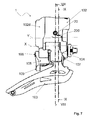
figure 1 is a perspective view of a motor driven derailleur according to the present invention; -
figure 2 is an exploded view of the derailleur offigure 1 ; -
figures 3 and4 are side views of the derailleur offigure 1 ; -
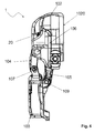
figure 5 is a section view of the derailleur offigure 1 , taken according to the plane line V - V offigure 3 ; -
figure 6 is an exploded view of a further embodiment of a motor driven derailleur according to the present invention, -
figure 7 is a side view of the derailleur offigure 6 ; -
figures 8 and 9 are section views of a portion of the derailleur offigure 6 , taken, respectively, according to the plane lines VIII - VIII and IX - IX offigure 7 . - With first reference to
figures 1-5 , a first embodiment of a motor driven derailleur for a bicycle gearshift in accordance with the present invention is shown. Such a derailleur is wholly indicated with 1. More specifically, a derailleur of the front gearshift is shown. - The following description is made with reference to the non-limiting case of the derailleur of the front gearshift; nevertheless, it can also refer, mutatis mutandis, to a derailleur of the rear gearshift having an analogous articulated parallelogram configuration.
- The
derailleur 1 of the front gearshift comprises an articulatedquadrilateral actuation mechanism 101, more precisely in the form of an articulated parallelogram, moved by agear motor unit 10, which is controlled by an electronic control board (not shown) driven by the cyclist. - The
gear motor unit 10 comprises anelectric motor 11 and amechanical reducer 12. The gear motor comprises anoutput shaft 13 that has a geared down number of revs with respect to the number of revs of a drive shaft of theelectric motor 11. - The
mechanism 101 comprises, at the four sides of the parallelogram, asupport body 102, achain guide 103 and a pair of connectingrods components - The
support body 102 is suitable for being mounted, at anattachment portion 1020 thereof, on a frame (not shown) of a bicycle. - The
gear motor unit 10 is housed inside thesupport body 102, accessible by removing asuitable cover 102d of thesupport body 102. - The
chain guide 103 is opposite thesupport body 102 in theactuation mechanism 101. Such achain guide 103 comprises the so-called "fork". In the case of a derailleur of the rear gearshift, the chain guide comprises, instead of the fork, an attachment portion to a rocker arm of the chain guide. - The connecting
rods chain guide 103 to thesupport body 102 in a mobile manner. - The connecting
rod 105 is also identified as "inner connecting rod" since it is the one that in use faces the frame of the bicycle, whereas the connectingrod 104 is identified as "outer connecting rod" since it is the one that in use faces the outside, i.e. arranged on the opposite side to the frame of the bicycle. - The
first pin 106 connects thesupport body 102 and the connectingrod 104, thesecond pin 107 connects thechain guide 103 and the connectingrod 104, thethird pin 108 connects thesupport body 102 and the connectingrod 105 and thefourth pin 109 connects thechain guide 103 and the connectingrod 105. - Preferably, the
first pin 106 and thesecond pin 107 are substantially the same as each other, just like thethird pin 108 and thefourth pin 109. - The connecting
rod 104 is able to rotate about a rotation axis X at afirst end 104a thereof provided with atoothed sector 104b. - The
toothed sector 104b is coupled with amatching toothed sector 14 of theoutput shaft 13 of thegear motor unit 10, able to rotate about a rotation axis Y. - The
toothed sector 14 of theoutput shaft 13 and thetoothed sector 104b of thefirst end 104a of the connectingrod 104 form a motion transmission between thegear motor unit 10 and the first connectingrod 104 and they are housed in aninner chamber 102a of thesupport body 102. - A part of the connecting
rod 104 juts out from theinner chamber 102a from a throughopening 102e of theinner chamber 102a. Between the throughopening 102e and the connectingrod 104gaskets 102f are provided to limit as much as possible the entry of water or other contaminating agents (like dust or mud) into theinner chamber 102a, which could compromise the correct operation of thederailleur 1. - In accordance with a characteristic of the present invention, the
inner chamber 102a comprises one or more adjustable end stop elements that prevent the rotation of theoutput shaft 13 beyond a certain rotation angle, in at least one of the two directions of rotation of theoutput shaft 13. - In the non-limiting case illustrated in
figures 1-5 , the end stop element is apin 20, which prevents the rotation of theoutput shaft 13 beyond a certain rotation angle in the clockwise direction of rotation (with reference tofigure 5 ) of theoutput shaft 13. - In other words, the
pin 20 intervenes to prevent the rotation of theoutput shaft 13 beyond a certain rotation angle that would cause the chain to drop out from the driving gear wheels, in a direction opposite to that facing towards the bicycle frame. - The
pin 20 is provided with an external threading that engages in a throughhole 102c, formed in awall 102b of thesupport body 102 and facing into theinner chamber 102a. - The position of the
pin 20 in thehole 102c is adjustable through screwing of thepin 20 into thehole 102c. - The through
hole 102c passes through thewall 102b of thesupport body 102, so that thepin 20 is accessible from the outside of thesupport body 102 when it is mounted on the bicycle frame. In the preferred embodiment illustrated infigures 1-5 , thepin 20 has ahead recess 20a at an outer free end thereof, which is suitable for being manoeuvred in rotation through an Allen key, a screwdriver or similar tool. - In the preferred embodiment illustrated in
figures 1-5 , theoutput shaft 13 comprises aradial projection 15 that hits thepin 20 in an end stop condition. - The
radial projection 15 is made, along the rotation axis Y, substantially at thetoothed sector 14 of theoutput shaft 13. In particular, theradial projection 15 is made on an angular part of theoutput shaft 13 that is distinct from an angular part where thetoothed sector 14 is made. -
Figures 6-9 show a further embodiment of the motor driven derailleur of the invention. In such figures, structural elements that are identical or equivalent from the functional point of view to those of the motor drivenderailleur 1 described above with reference tofigures 1-5 will be attributed the same reference numerals and they will not be described any further. - In particular, this further embodiment of the
derailleur 1 of the invention differs from thederailleur 1 offigures 1-5 in that it comprises a further end stop element formed by afurther pin 220 that prevents the rotation of theoutput shaft 13 beyond a certain rotation angle in the direction of rotation of theoutput shaft 13 opposite to that in which thepin 20 intervenes, i.e. a rotation angle that causes the chain to drop towards the bicycle frame. In other words, thefurther pin 220 prevents the rotation of theoutput shaft 13 beyond a certain rotation angle in the clockwise direction of rotation (with reference tofigures 8 and 9 ) of theoutput shaft 13. - The
further pin 220 is provided with an external threading, which engages in a further throughhole 202c, at least partially threaded, formed in thewall 102b of thesupport body 102 and facing into theinner chamber 102a. - The position of the
further pin 220 in thefurther hole 202c is adjustable through screwing of thefurther pin 220 into thefurther hole 202c. - The further through
hole 202c passes through thewall 102b of thesupport body 102, so that thefurther pin 220 is accessible from the outside of thesupport body 102 when it is mounted on the bicycle frame. In the preferred embodiment illustrated infigures 6-9 , thefurther pin 220 has ahead recess 220a at an outer end thereof, which is suitable for being manoeuvred in rotation through an Allen key, a screwdriver or similar tool. - In the preferred embodiment illustrated in
figures 6-9 , theoutput shaft 13 comprises a furtherradial projection 215 that hits thepin 220 in a further end stop condition. - The further
radial projection 215 is made in aportion 213a of theoutput shaft 13 that is adjacent, along the rotation axis Y, to aportion 214a where thetoothed sector 14 is made. - In particular, in the preferred embodiment illustrated in
figures 6-9 , theportion 213a is arranged axially farther outside theportion 214a with respect to themechanical reducer 12 of thegear motor unit 10. - The operation of the
derailleur 1 according to the present invention is already clear from what has been stated above, and it is described further hereafter. - In the case of the embodiment of
figures 1-5 , thederailleur 1 is first mounted on the bicycle frame. - Then the end stop element is adjusted, i.e. the position of the
pin 20 in thehole 102c of thesupport body 102 is adjusted. - Such adjustment is carried out by acting on the
head recess 20a of thepin 20 with an Allen key, a screwdriver or similar tool, so as to screw thepin 20 into thehole 102c by a suitable amount. - In particular, the
output shaft 13 is rotated until theradial projection 15 abuts on thepin 20. By checking the corresponding position taken up by the chain guide 103 (kinematically connected to theoutput shaft 13 through the connecting rod 104), the position of thepin 20 is adjusted so that theoutput shaft 13 cannot rotate beyond a certain rotation angle that would take thechain guide 103 into a position in which the chain would fall outside of the gears of the crankset (or the sprockets of the sprocket set, in the case of a derailleur of the rear gearshift), in a direction towards the outside with respect to the bicycle frame. - Also in the case of the embodiment of
figures 6-9 , thederailleur 1 is first mounted onto the bicycle frame. - Then the end stop elements are adjusted, i.e. the positions of the
pin 20 in thehole 102c and of thefurther pin 220 in thefurther hole 202c are adjusted. - Such adjustment is carried out by acting on the
head recess pins pins holes - In particular, the
output shaft 13 is rotated until theradial projection 15 abuts on thepin 20. By checking the corresponding position taken up by the chain guide 103 (kinematically connected to theoutput shaft 13 through the connecting rod 104), the position of thepin 20 is adjusted so that theoutput shaft 13 cannot rotate beyond a certain rotation angle that would take thechain guide 103 into a position in which the chain would fall outside of the gears of the crankset (or the sprockets of the sprocket set, in the case of a derailleur of the rear gearshift), in a direction towards the outside with respect to the bicycle frame. - Moreover, the
output shaft 13 is rotated until theradial projection 215 abuts on thefurther pin 220. By checking the corresponding position taken up by the chain guide 103 (kinematically connected to theoutput shaft 13 through the connecting rod 104), the position of thefurther pin 220 is adjusted so that theoutput shaft 13 cannot rotate beyond a certain rotation angle that would take thechain guide 103 into a position in which the chain would fall inside the gears of the crankset (or the sprockets of the sprocket set, in the case of a derailleur of the rear gearshift), in a direction towards the bicycle frame. - Preferably, the connecting
rod 104 is made from light metallic material or from composite material. In this way, a lightweight derailleur is obtained, which is particularly sought after in the case in which it is intended to be used on a racing bicycle. - By compound material a material is meant consisting of at least two components including a polymeric matrix and a filler comprising, for example, structural fibres, granules or powders. The structural fibres are preferably selected from the group consisting of carbon fibres, glass fibres, aramid fibres, ceramic fibres, boron fibres and combinations thereof. Carbon fibres are particularly preferred. Preferably, the polymeric material is thermosetting and preferably comprises an epoxy resin. However, this does not rule out the possibility of using a thermoplastic material.
- Preferably, the
pin 20 is made from metallic material. - In the case in which the
support body 102 is made from composite material, thehole 102c can be made on a metallic insert inserted in thewall 102b of thesupport body 102. The metallic insert is blocked in thewall 102b, for example through gluing or mechanical interference or with other equivalent blocking means, or it is co-moulded in thewall 102b. - Although the invention has been described and illustrated with reference only to the coupling between the
support body 102 and the connectingrod 104, alternatively it can be applied in a totally analogous manner to the coupling between thesupport body 102 and the connecting rod 105 (or theoutput shaft 13 of thegear motor unit 10 can be coupled with the connectingrod 105 instead of with the connecting rod 104). - Of course, a man skilled in the art can bring many modifications and variants to the motor driven derailleur for a bicycle gearshift and to the bicycle gearshift described above, in order to satisfy specific and contingent requirements, all of which are in any case covered by the scope of protection of the present invention as defined by the following claims.
Claims (11)
- Motor actuated derailleur (1) for a bicycle gearshift, comprising:- a support body (102) suitable for being mounted on a bicycle frame,- a chain guide (103) suitable for moving a bicycle chain between different engaged positions on respective gear wheels,- a pair of connecting rods (104, 105) that connect said chain guide (103) to said support body (102) in a mobile manner, a first connecting rod (104) of said pair of connecting rods (104, 105) being rotatable about a first rotation axis (X) at a first end (104a) thereof,- a gear motor unit (10), housed in said support body (102) and provided with an output shaft (13) able to rotate about a second rotation axis (Y),- a motion transmission (14, 104b) between said gear motor unit (10) and said first connecting rod (104), housed in an inner chamber (102a) of said support body (102),characterised in that said inner chamber (102a) comprises at least one adjustable end stop element (20, 220) that prevents the rotation of the output shaft (13) beyond a certain rotation angle, in at least one of the two directions of rotation of the output shaft (13).
- Derailleur (1) according to claim 1, wherein said motion transmission comprises a first toothed sector (104b) formed on said first connecting rod (104) at said first end (104a), and a second toothed sector (14) formed on said output shaft (13), the second toothed sector (14) matching and coupling with the first toothed sector (104b).
- Derailleur (1) according to claim 1 or 2, wherein said at least one end stop element is a pin (20) provided with external threading, which engages in a threaded through hole (102c) formed in a wall (102b) of said support body (102) and facing into said inner chamber (102a), wherein the position of said pin (20) in said hole (102c) is adjustable through screwing of the pin (20) in the hole (102c).
- Derailleur (1) according to claim 3, wherein said output shaft (13) comprises a radial projection (15) that hits said pin (20) in an end stop condition.
- Derailleur (1) according to claim 4, wherein said radial projection (15) is made, along the second rotation axis (Y), substantially at said second toothed sector (14).
- Derailleur (1) according to any one of the previous claims, wherein said at least one end stop element (20) prevents the rotation of the output shaft (13) beyond a certain rotation angle in the direction of rotation that corresponds to a movement of the chain guide (103) towards the outside with respect to the bicycle frame on which the derailleur (1) is mounted.
- Derailleur (1) according to any one of claims 3 to 6, wherein said at least one end stop element comprises a further pin (220) provided with an external threading, which engages in a further threaded through hole (202c) formed in said wall (102b) of said support body (102) and facing into said inner chamber (102a), wherein the position of said further pin (220) in said further hole (202c) is adjustable through screwing of the further pin (220) in the further hole (202c).
- Derailleur (1) according to claim 7, wherein said output shaft comprises a further radial projection (215) that hits said further pin (220) in a further end stop condition, and prevents the rotation of the output shaft beyond a certain rotation angle in the direction of rotation that corresponds to a movement of the chain guide (103) towards the bicycle frame on which the derailleur (1) is mounted.
- Derailleur (1) according to claim 8, wherein said further radial projection (215) is made in a respective portion (213a) of the output shaft (13) that is beside, along the second rotation axis (Y), a portion (214a) where said second toothed sector (14) is made.
- Derailleur (1) according to any one of the previous claims, wherein said gearshift is a front gearshift.
- Bicycle gearshift comprising a derailleur (1) according to any one of the previous claims.
Applications Claiming Priority (1)
| Application Number | Priority Date | Filing Date | Title |
|---|---|---|---|
| IT001825A ITMI20131825A1 (en) | 2013-11-04 | 2013-11-04 | MOTORIZED DRIVE DERAILLEUR FOR A BICYCLE CHANGE |
Publications (2)
| Publication Number | Publication Date |
|---|---|
| EP2868566A1 true EP2868566A1 (en) | 2015-05-06 |
| EP2868566B1 EP2868566B1 (en) | 2016-03-09 |
Family
ID=49887068
Family Applications (1)
| Application Number | Title | Priority Date | Filing Date |
|---|---|---|---|
| EP14191401.0A Active EP2868566B1 (en) | 2013-11-04 | 2014-11-03 | Motor driven derailleur for a bicycle gearshift |
Country Status (6)
| Country | Link |
|---|---|
| US (1) | US9573653B2 (en) |
| EP (1) | EP2868566B1 (en) |
| JP (1) | JP6532211B2 (en) |
| CN (1) | CN104608873B (en) |
| IT (1) | ITMI20131825A1 (en) |
| TW (1) | TWI646018B (en) |
Cited By (5)
| Publication number | Priority date | Publication date | Assignee | Title |
|---|---|---|---|---|
| EP3578451A3 (en) * | 2018-05-15 | 2020-03-04 | SRAM Deutschland GmbH | Actuators for a bicycle and method for controlling or adjusting such actuators |
| US11565772B2 (en) | 2020-06-30 | 2023-01-31 | Shimano Inc. | Bicycle derailleur, bicycle gear structure, bicycle motor unit, and front derailleur |
| US11697474B2 (en) | 2020-06-30 | 2023-07-11 | Shimano Inc. | Bicycle derailleur and link pin for bicycle derailleur |
| US11745828B2 (en) | 2020-06-30 | 2023-09-05 | Shimano Inc. | Front derailleur and chain guide of bicycle derailleur |
| IT202200009935A1 (en) * | 2022-05-13 | 2023-11-13 | Campagnolo Srl | Electric/electronic bicycle derailleur with articulated parallelogram |
Families Citing this family (13)
| Publication number | Priority date | Publication date | Assignee | Title |
|---|---|---|---|---|
| US9334017B2 (en) * | 2014-03-14 | 2016-05-10 | Tien Hsin Industries Co., Ltd. | Electronic rear derailleur |
| US9776684B2 (en) * | 2014-10-17 | 2017-10-03 | Tektro Technology Corporation | Derailleur |
| ITUA201696738U1 (en) * | 2016-05-04 | 2017-11-04 | Campagnolo Srl | ACTUATOR DEVICE FOR A BICYCLE CHANGE AND ITS BICYCLE CHANGE. |
| ITUA20163996A1 (en) * | 2016-05-31 | 2017-12-01 | Campagnolo Srl | Electric bicycle derailleur |
| IT201600076517A1 (en) * | 2016-07-21 | 2018-01-21 | Campagnolo Srl | BICYCLE CHANGE |
| DE102019103897A1 (en) * | 2019-02-15 | 2020-08-20 | Shimano Inc. | FRONT BICYCLE DERAILLEUR |
| TWI723397B (en) * | 2019-03-19 | 2021-04-01 | 彥豪金屬工業股份有限公司 | Bicycle rear derailleur |
| DE102020211139A1 (en) | 2020-06-30 | 2021-12-30 | Shimano Inc. | MOTOR UNIT FOR BICYCLE DERAILLEUR |
| US11685469B2 (en) * | 2020-09-11 | 2023-06-27 | Shimano Inc. | Bicycle derailleur |
| CN115946807A (en) * | 2023-01-03 | 2023-04-11 | 珠海蓝图运动科技股份有限公司 | Front derailleur |
| US11794856B2 (en) | 2023-02-14 | 2023-10-24 | Hazem Nihad Hamed | Front derailleur electrical actuator |
| CN117719624A (en) * | 2024-01-16 | 2024-03-19 | 青岛迈金智能科技股份有限公司 | Electronic transmission and riding equipment |
| US12246797B1 (en) * | 2024-11-19 | 2025-03-11 | Hazem Nihad Hamed | Front derailleur with integral cadence sensor |
Citations (3)
| Publication number | Priority date | Publication date | Assignee | Title |
|---|---|---|---|---|
| FR2247376A1 (en) * | 1973-10-15 | 1975-05-09 | Stuhlmuller Brian | |
| EP1310423A2 (en) * | 2001-11-09 | 2003-05-14 | Shimano Inc. | Motorized bicycle actuator assembly |
| EP1818253A2 (en) * | 2006-02-08 | 2007-08-15 | Shimano Inc. | Motorized bicycle derailleur assembly |
Family Cites Families (8)
| Publication number | Priority date | Publication date | Assignee | Title |
|---|---|---|---|---|
| FR2093242A5 (en) * | 1970-06-08 | 1972-01-28 | Juy Lucien | |
| IT1320581B1 (en) * | 2000-08-03 | 2003-12-10 | Campagnolo Srl | FRONT BIKE FRONT DERAILLEUR WITH ELECTRIC CONTROL MOTOR AND GEAR REDUCER. |
| US7341532B2 (en) * | 2004-02-27 | 2008-03-11 | Shimano Inc. | Electric derailleur motor unit |
| US7503863B2 (en) * | 2005-02-18 | 2009-03-17 | Shimano Inc. | Bicycle derailleur motor unit assembly |
| US7722486B2 (en) * | 2005-12-14 | 2010-05-25 | Shimano Inc. | Top/bottom pull bicycle front derailleur |
| US7942768B2 (en) * | 2008-01-28 | 2011-05-17 | Shimano, Inc. | Electrically operated derailleur that re-engages a disengaged derailleur force overload clutch |
| US9555856B2 (en) * | 2013-03-25 | 2017-01-31 | Shimano Inc. | Electric front derailleur |
| US9085340B1 (en) * | 2014-03-14 | 2015-07-21 | Tien Hsin Industries Co., Ltd. | Electronic front derailleur |
-
2013
- 2013-11-04 IT IT001825A patent/ITMI20131825A1/en unknown
-
2014
- 2014-10-21 TW TW103136335A patent/TWI646018B/en active
- 2014-10-29 JP JP2014220160A patent/JP6532211B2/en active Active
- 2014-11-03 EP EP14191401.0A patent/EP2868566B1/en active Active
- 2014-11-04 US US14/532,370 patent/US9573653B2/en active Active
- 2014-11-04 CN CN201410612620.0A patent/CN104608873B/en active Active
Patent Citations (3)
| Publication number | Priority date | Publication date | Assignee | Title |
|---|---|---|---|---|
| FR2247376A1 (en) * | 1973-10-15 | 1975-05-09 | Stuhlmuller Brian | |
| EP1310423A2 (en) * | 2001-11-09 | 2003-05-14 | Shimano Inc. | Motorized bicycle actuator assembly |
| EP1818253A2 (en) * | 2006-02-08 | 2007-08-15 | Shimano Inc. | Motorized bicycle derailleur assembly |
Cited By (11)
| Publication number | Priority date | Publication date | Assignee | Title |
|---|---|---|---|---|
| EP3578451A3 (en) * | 2018-05-15 | 2020-03-04 | SRAM Deutschland GmbH | Actuators for a bicycle and method for controlling or adjusting such actuators |
| US11312449B2 (en) | 2018-05-15 | 2022-04-26 | Sram Deutschland Gmbh | Electromechanical derailleur |
| US11731733B2 (en) | 2018-05-15 | 2023-08-22 | Sram Deutschland Gmbh | Electromechanical derailleur |
| US12485995B2 (en) | 2018-05-15 | 2025-12-02 | Sram Deutschland Gmbh | Electromechanical derailleur |
| US11565772B2 (en) | 2020-06-30 | 2023-01-31 | Shimano Inc. | Bicycle derailleur, bicycle gear structure, bicycle motor unit, and front derailleur |
| US11697474B2 (en) | 2020-06-30 | 2023-07-11 | Shimano Inc. | Bicycle derailleur and link pin for bicycle derailleur |
| US11745828B2 (en) | 2020-06-30 | 2023-09-05 | Shimano Inc. | Front derailleur and chain guide of bicycle derailleur |
| US12151783B2 (en) | 2020-06-30 | 2024-11-26 | Shimano Inc. | Chain guide of bicycle derailleur |
| IT202200009935A1 (en) * | 2022-05-13 | 2023-11-13 | Campagnolo Srl | Electric/electronic bicycle derailleur with articulated parallelogram |
| EP4276003A1 (en) * | 2022-05-13 | 2023-11-15 | Campagnolo S.r.l. | Bicycle electric/electronic derailleur of the articulated parallelogram type |
| US12024263B2 (en) | 2022-05-13 | 2024-07-02 | Campagnolo S.R.L. | Articulated parallelogram bicycle electric/electronic derailleur |
Also Published As
| Publication number | Publication date |
|---|---|
| ITMI20131825A1 (en) | 2015-05-05 |
| US20150126314A1 (en) | 2015-05-07 |
| CN104608873B (en) | 2017-08-29 |
| US9573653B2 (en) | 2017-02-21 |
| CN104608873A (en) | 2015-05-13 |
| JP6532211B2 (en) | 2019-06-19 |
| JP2015089810A (en) | 2015-05-11 |
| TW201529415A (en) | 2015-08-01 |
| EP2868566B1 (en) | 2016-03-09 |
| TWI646018B (en) | 2019-01-01 |
Similar Documents
| Publication | Publication Date | Title |
|---|---|---|
| EP2868566B1 (en) | Motor driven derailleur for a bicycle gearshift | |
| EP2022712B1 (en) | Motion transmission system of a bicycle | |
| US10351208B2 (en) | Bicycle rear derailleur | |
| CN102464086B (en) | Position control mechanism | |
| US8202182B2 (en) | Motion resisting apparatus for a bicycle derailleur | |
| US9045193B2 (en) | Command device for a derailleur of a bicycle | |
| US20090062045A1 (en) | Bicycle rear derailleur | |
| TWI745484B (en) | Rear derailleur | |
| TWI672248B (en) | Bicycle chain device | |
| CN1453180A (en) | Actuator for bicycle speed-changing device | |
| CN103318372A (en) | Drive assembly for a bicycle with high tooth ratio between largest and smallest rear chain sprocket | |
| TW201836917A (en) | Bicycle rear derailleur | |
| EP1630092B1 (en) | Transmission | |
| US20130137541A1 (en) | Gear transmission and derrailleur system | |
| CN1572653A (en) | Bicycle shift control device | |
| KR101961589B1 (en) | Bicycle transmission system using variable speed motor and planetary gear mechanism | |
| EP2052958A1 (en) | Bicycle gearshift | |
| TWI650269B (en) | Bicycle drive system | |
| US20180001961A1 (en) | Bicycle tensioner apparatus and bicycle tensioner | |
| CN202923826U (en) | Transmission device and bicycle including the transmission device | |
| EP2918489A1 (en) | Asymmetric elliptical chainring capable of fine-angle variation, and crankset of bicycle comprising same | |
| EP2110304A1 (en) | Bicycle derailleur | |
| WO2017033068A1 (en) | Device for motion transmission on cycles | |
| EP2110305A1 (en) | Bicycle derailleur | |
| US20130053198A1 (en) | Bicycle derailleur cover |
Legal Events
| Date | Code | Title | Description |
|---|---|---|---|
| PUAI | Public reference made under article 153(3) epc to a published international application that has entered the european phase |
Free format text: ORIGINAL CODE: 0009012 |
|
| 17P | Request for examination filed |
Effective date: 20141103 |
|
| AK | Designated contracting states |
Kind code of ref document: A1 Designated state(s): AL AT BE BG CH CY CZ DE DK EE ES FI FR GB GR HR HU IE IS IT LI LT LU LV MC MK MT NL NO PL PT RO RS SE SI SK SM TR |
|
| AX | Request for extension of the european patent |
Extension state: BA ME |
|
| R17P | Request for examination filed (corrected) |
Effective date: 20150720 |
|
| RBV | Designated contracting states (corrected) |
Designated state(s): AL AT BE BG CH CY CZ DE DK EE ES FI FR GB GR HR HU IE IS IT LI LT LU LV MC MK MT NL NO PL PT RO RS SE SI SK SM TR |
|
| GRAP | Despatch of communication of intention to grant a patent |
Free format text: ORIGINAL CODE: EPIDOSNIGR1 |
|
| RIC1 | Information provided on ipc code assigned before grant |
Ipc: B62M 9/00 20060101ALN20150811BHEP Ipc: B62M 9/122 20100101AFI20150811BHEP Ipc: B62M 9/126 20100101ALI20150811BHEP Ipc: B62M 9/132 20100101ALI20150811BHEP |
|
| INTG | Intention to grant announced |
Effective date: 20150831 |
|
| GRAS | Grant fee paid |
Free format text: ORIGINAL CODE: EPIDOSNIGR3 |
|
| GRAA | (expected) grant |
Free format text: ORIGINAL CODE: 0009210 |
|
| AK | Designated contracting states |
Kind code of ref document: B1 Designated state(s): AL AT BE BG CH CY CZ DE DK EE ES FI FR GB GR HR HU IE IS IT LI LT LU LV MC MK MT NL NO PL PT RO RS SE SI SK SM TR |
|
| REG | Reference to a national code |
Ref country code: GB Ref legal event code: FG4D |
|
| REG | Reference to a national code |
Ref country code: AT Ref legal event code: REF Ref document number: 779266 Country of ref document: AT Kind code of ref document: T Effective date: 20160315 Ref country code: CH Ref legal event code: EP |
|
| REG | Reference to a national code |
Ref country code: IE Ref legal event code: FG4D |
|
| REG | Reference to a national code |
Ref country code: DE Ref legal event code: R096 Ref document number: 602014001056 Country of ref document: DE |
|
| REG | Reference to a national code |
Ref country code: LT Ref legal event code: MG4D |
|
| REG | Reference to a national code |
Ref country code: NL Ref legal event code: MP Effective date: 20160309 |
|
| PG25 | Lapsed in a contracting state [announced via postgrant information from national office to epo] |
Ref country code: GR Free format text: LAPSE BECAUSE OF FAILURE TO SUBMIT A TRANSLATION OF THE DESCRIPTION OR TO PAY THE FEE WITHIN THE PRESCRIBED TIME-LIMIT Effective date: 20160610 Ref country code: NO Free format text: LAPSE BECAUSE OF FAILURE TO SUBMIT A TRANSLATION OF THE DESCRIPTION OR TO PAY THE FEE WITHIN THE PRESCRIBED TIME-LIMIT Effective date: 20160609 Ref country code: HR Free format text: LAPSE BECAUSE OF FAILURE TO SUBMIT A TRANSLATION OF THE DESCRIPTION OR TO PAY THE FEE WITHIN THE PRESCRIBED TIME-LIMIT Effective date: 20160309 Ref country code: ES Free format text: LAPSE BECAUSE OF FAILURE TO SUBMIT A TRANSLATION OF THE DESCRIPTION OR TO PAY THE FEE WITHIN THE PRESCRIBED TIME-LIMIT Effective date: 20160309 Ref country code: FI Free format text: LAPSE BECAUSE OF FAILURE TO SUBMIT A TRANSLATION OF THE DESCRIPTION OR TO PAY THE FEE WITHIN THE PRESCRIBED TIME-LIMIT Effective date: 20160309 |
|
| REG | Reference to a national code |
Ref country code: AT Ref legal event code: MK05 Ref document number: 779266 Country of ref document: AT Kind code of ref document: T Effective date: 20160309 |
|
| PG25 | Lapsed in a contracting state [announced via postgrant information from national office to epo] |
Ref country code: SE Free format text: LAPSE BECAUSE OF FAILURE TO SUBMIT A TRANSLATION OF THE DESCRIPTION OR TO PAY THE FEE WITHIN THE PRESCRIBED TIME-LIMIT Effective date: 20160309 Ref country code: LT Free format text: LAPSE BECAUSE OF FAILURE TO SUBMIT A TRANSLATION OF THE DESCRIPTION OR TO PAY THE FEE WITHIN THE PRESCRIBED TIME-LIMIT Effective date: 20160309 Ref country code: NL Free format text: LAPSE BECAUSE OF FAILURE TO SUBMIT A TRANSLATION OF THE DESCRIPTION OR TO PAY THE FEE WITHIN THE PRESCRIBED TIME-LIMIT Effective date: 20160309 Ref country code: RS Free format text: LAPSE BECAUSE OF FAILURE TO SUBMIT A TRANSLATION OF THE DESCRIPTION OR TO PAY THE FEE WITHIN THE PRESCRIBED TIME-LIMIT Effective date: 20160309 Ref country code: PL Free format text: LAPSE BECAUSE OF FAILURE TO SUBMIT A TRANSLATION OF THE DESCRIPTION OR TO PAY THE FEE WITHIN THE PRESCRIBED TIME-LIMIT Effective date: 20160309 Ref country code: LV Free format text: LAPSE BECAUSE OF FAILURE TO SUBMIT A TRANSLATION OF THE DESCRIPTION OR TO PAY THE FEE WITHIN THE PRESCRIBED TIME-LIMIT Effective date: 20160309 |
|
| PG25 | Lapsed in a contracting state [announced via postgrant information from national office to epo] |
Ref country code: EE Free format text: LAPSE BECAUSE OF FAILURE TO SUBMIT A TRANSLATION OF THE DESCRIPTION OR TO PAY THE FEE WITHIN THE PRESCRIBED TIME-LIMIT Effective date: 20160309 Ref country code: IS Free format text: LAPSE BECAUSE OF FAILURE TO SUBMIT A TRANSLATION OF THE DESCRIPTION OR TO PAY THE FEE WITHIN THE PRESCRIBED TIME-LIMIT Effective date: 20160709 |
|
| REG | Reference to a national code |
Ref country code: FR Ref legal event code: PLFP Year of fee payment: 3 |
|
| PG25 | Lapsed in a contracting state [announced via postgrant information from national office to epo] |
Ref country code: CZ Free format text: LAPSE BECAUSE OF FAILURE TO SUBMIT A TRANSLATION OF THE DESCRIPTION OR TO PAY THE FEE WITHIN THE PRESCRIBED TIME-LIMIT Effective date: 20160309 Ref country code: PT Free format text: LAPSE BECAUSE OF FAILURE TO SUBMIT A TRANSLATION OF THE DESCRIPTION OR TO PAY THE FEE WITHIN THE PRESCRIBED TIME-LIMIT Effective date: 20160711 Ref country code: RO Free format text: LAPSE BECAUSE OF FAILURE TO SUBMIT A TRANSLATION OF THE DESCRIPTION OR TO PAY THE FEE WITHIN THE PRESCRIBED TIME-LIMIT Effective date: 20160309 Ref country code: SM Free format text: LAPSE BECAUSE OF FAILURE TO SUBMIT A TRANSLATION OF THE DESCRIPTION OR TO PAY THE FEE WITHIN THE PRESCRIBED TIME-LIMIT Effective date: 20160309 Ref country code: AT Free format text: LAPSE BECAUSE OF FAILURE TO SUBMIT A TRANSLATION OF THE DESCRIPTION OR TO PAY THE FEE WITHIN THE PRESCRIBED TIME-LIMIT Effective date: 20160309 Ref country code: SK Free format text: LAPSE BECAUSE OF FAILURE TO SUBMIT A TRANSLATION OF THE DESCRIPTION OR TO PAY THE FEE WITHIN THE PRESCRIBED TIME-LIMIT Effective date: 20160309 |
|
| REG | Reference to a national code |
Ref country code: DE Ref legal event code: R097 Ref document number: 602014001056 Country of ref document: DE |
|
| PG25 | Lapsed in a contracting state [announced via postgrant information from national office to epo] |
Ref country code: BE Free format text: LAPSE BECAUSE OF FAILURE TO SUBMIT A TRANSLATION OF THE DESCRIPTION OR TO PAY THE FEE WITHIN THE PRESCRIBED TIME-LIMIT Effective date: 20160309 |
|
| PLBE | No opposition filed within time limit |
Free format text: ORIGINAL CODE: 0009261 |
|
| STAA | Information on the status of an ep patent application or granted ep patent |
Free format text: STATUS: NO OPPOSITION FILED WITHIN TIME LIMIT |
|
| PG25 | Lapsed in a contracting state [announced via postgrant information from national office to epo] |
Ref country code: DK Free format text: LAPSE BECAUSE OF FAILURE TO SUBMIT A TRANSLATION OF THE DESCRIPTION OR TO PAY THE FEE WITHIN THE PRESCRIBED TIME-LIMIT Effective date: 20160309 |
|
| 26N | No opposition filed |
Effective date: 20161212 |
|
| PG25 | Lapsed in a contracting state [announced via postgrant information from national office to epo] |
Ref country code: BG Free format text: LAPSE BECAUSE OF FAILURE TO SUBMIT A TRANSLATION OF THE DESCRIPTION OR TO PAY THE FEE WITHIN THE PRESCRIBED TIME-LIMIT Effective date: 20160609 |
|
| PG25 | Lapsed in a contracting state [announced via postgrant information from national office to epo] |
Ref country code: SI Free format text: LAPSE BECAUSE OF FAILURE TO SUBMIT A TRANSLATION OF THE DESCRIPTION OR TO PAY THE FEE WITHIN THE PRESCRIBED TIME-LIMIT Effective date: 20160309 |
|
| REG | Reference to a national code |
Ref country code: IE Ref legal event code: MM4A |
|
| PG25 | Lapsed in a contracting state [announced via postgrant information from national office to epo] |
Ref country code: LU Free format text: LAPSE BECAUSE OF NON-PAYMENT OF DUE FEES Effective date: 20161130 |
|
| REG | Reference to a national code |
Ref country code: FR Ref legal event code: PLFP Year of fee payment: 4 |
|
| PG25 | Lapsed in a contracting state [announced via postgrant information from national office to epo] |
Ref country code: IE Free format text: LAPSE BECAUSE OF NON-PAYMENT OF DUE FEES Effective date: 20161103 |
|
| PG25 | Lapsed in a contracting state [announced via postgrant information from national office to epo] |
Ref country code: HU Free format text: LAPSE BECAUSE OF FAILURE TO SUBMIT A TRANSLATION OF THE DESCRIPTION OR TO PAY THE FEE WITHIN THE PRESCRIBED TIME-LIMIT; INVALID AB INITIO Effective date: 20141103 |
|
| PG25 | Lapsed in a contracting state [announced via postgrant information from national office to epo] |
Ref country code: MC Free format text: LAPSE BECAUSE OF FAILURE TO SUBMIT A TRANSLATION OF THE DESCRIPTION OR TO PAY THE FEE WITHIN THE PRESCRIBED TIME-LIMIT Effective date: 20160309 Ref country code: CY Free format text: LAPSE BECAUSE OF FAILURE TO SUBMIT A TRANSLATION OF THE DESCRIPTION OR TO PAY THE FEE WITHIN THE PRESCRIBED TIME-LIMIT Effective date: 20160309 Ref country code: MK Free format text: LAPSE BECAUSE OF FAILURE TO SUBMIT A TRANSLATION OF THE DESCRIPTION OR TO PAY THE FEE WITHIN THE PRESCRIBED TIME-LIMIT Effective date: 20160309 |
|
| PG25 | Lapsed in a contracting state [announced via postgrant information from national office to epo] |
Ref country code: LI Free format text: LAPSE BECAUSE OF NON-PAYMENT OF DUE FEES Effective date: 20171130 Ref country code: CH Free format text: LAPSE BECAUSE OF NON-PAYMENT OF DUE FEES Effective date: 20171130 |
|
| PG25 | Lapsed in a contracting state [announced via postgrant information from national office to epo] |
Ref country code: MT Free format text: LAPSE BECAUSE OF NON-PAYMENT OF DUE FEES Effective date: 20161103 |
|
| PG25 | Lapsed in a contracting state [announced via postgrant information from national office to epo] |
Ref country code: AL Free format text: LAPSE BECAUSE OF FAILURE TO SUBMIT A TRANSLATION OF THE DESCRIPTION OR TO PAY THE FEE WITHIN THE PRESCRIBED TIME-LIMIT Effective date: 20160309 Ref country code: TR Free format text: LAPSE BECAUSE OF FAILURE TO SUBMIT A TRANSLATION OF THE DESCRIPTION OR TO PAY THE FEE WITHIN THE PRESCRIBED TIME-LIMIT Effective date: 20160309 |
|
| P01 | Opt-out of the competence of the unified patent court (upc) registered |
Effective date: 20230516 |
|
| PGFP | Annual fee paid to national office [announced via postgrant information from national office to epo] |
Ref country code: DE Payment date: 20251128 Year of fee payment: 12 |
|
| PGFP | Annual fee paid to national office [announced via postgrant information from national office to epo] |
Ref country code: GB Payment date: 20251127 Year of fee payment: 12 |
|
| PGFP | Annual fee paid to national office [announced via postgrant information from national office to epo] |
Ref country code: IT Payment date: 20251119 Year of fee payment: 12 |
|
| PGFP | Annual fee paid to national office [announced via postgrant information from national office to epo] |
Ref country code: FR Payment date: 20251125 Year of fee payment: 12 |